Article

Enhancement Analysis of Damaged Masonry Structures Strengthened with Ultra-High-Performance Concrete

1
School of Civil Engineering, Harbin Institute of Technology, Harbin 150001, China
2
Heilongjiang Construction Group Co., Ltd., Harbin 150036, China
3
Heilongjiang Wujian Construction Engineering Co., Ltd., Harbin 150090, China
4
College of Civil Engineering, Fuzhou University, Fuzhou 350108, China
5
Key Lab of Structures Dynamic Behavior and Control of the Ministry of Education, Harbin Institute of Technology, Harbin 150090, China
6
Jiangxi Building Materials Research and Design Institute Co., Ltd., Nanchang 330001, China
7
Jian Yan Test Group Company Limited, Xiamen 361004, China
*
Authors to whom correspondence should be addressed.
Buildings 2025, 15(12), 2082; https://doi.org/10.3390/buildings15122082
Submission received: 19 March 2025 / Revised: 7 June 2025 / Accepted: 11 June 2025 / Published: 17 June 2025

Abstract

In order to enhance the seismic performance of existing masonry structures and optimize the thickness of the strengthening layer, ultra-high-performance concrete (UHPC) can be used as an enhancement material. Based on current concrete strengthening methods, the bearing capacity and seismic behavior of existing masonry structures strengthened with UHPC were investigated numerically. The effects of the strengthening layer thickness and reinforcement ratio on the structural strengthening results were analyzed numerically. The structural behaviors before and after an earthquake, with various strengthening methods, were compared and discussed. The results show that the ratio of axial resistance to shear resistance increases linearly with the resistance ratio. The seismic performance of damaged masonry walls can be improved by about 150% and 250% when 20 mm thick double-sided plain UHPC layers and 30 mm thick double-sided plain UHPC layers are used for strengthening, respectively. The axial compression ratio of masonry walls can be reduced by about 60–70% when double-sided plain UHPC layers are used for strengthening.

1. Introduction

In masonry structures, environmental factors can degrade the properties of masonry mortar. In particular, due to the relatively low seismic performance of rural houses built in the 1970s, these masonry structures typically do not meet the relevant seismic standard requirements. After the Songyuan earthquake (magnitude 5.7 and focal depth of 10–20 km) and other frequent earthquakes, masonry structures in rural areas were seriously damaged (i.e., cracking, corner damage, connection failure in walls, and damage to staircases, floors, and roofs). However, no significant deformation or large cracks occurred in the buildings; small cracks developed in the external and internal walls. In existing masonry structures, the mortar exhibits low strength recovery, which reduces the block strength under axial compression. Further, structural concrete columns are not used in the existing masonry structures, which does not meet the relevant requirements of the current seismic design code [1].
To protect existing masonry building structures from small-to-moderate earthquakes, the structural integrity and seismic performance of the masonry structures must be strengthened effectively. As standard seismic enhancement methods for masonry structures, surface layers such as reinforced concrete (RC) surface layers, reinforced mesh cement mortar, textile-reinforced concrete, and pasting fiber composite materials can be utilized [2,3].
Engineered cementitious composites (ECC) have been widely used in engineering enhancement due to their high toughness. Sayin and Calayir [4] studied the linear and non-linear response of a masonry wall with an opening. Karaca et al. [5] presented several enhancement techniques for existing masonry structures. Laib et al. [6] investigated the free vibration behavior of a navigation wall strengthened with a thin composite plate using a viscoelastic adhesive layer. Koksal et al. [7] developed a practical method for modeling fiber-reinforced polymer (FRP) reinforced masonry panels. Mercedes et al. [8] used plant fiber FRCM (fabric-reinforced cementing matrix) as an enhancement material for masonry structures. Deng et al. [9] reported that the displacement and energy dissipation of walls strengthened with an ECC overlay significantly increased. Choi et al. [10] found that the strength, ductility, and energy dissipation capacity of a wall strengthened with ECC were significantly improved. Bui et al. [11] reported that fiber-reinforced polymer strips and fiber-reinforced concrete improved the shear resistance and energy dissipation capacity of masonry walls. Sharbatdar and Tajari [12] reported that the load-carrying capacity, stiffness, and energy dissipation capacity of masonry-infilled RC frames, strengthened by ECC for filling and reinforcement, increased by 215%, 32%, and 102%, respectively.
Separation at the corners of buildings can be caused by seismic residual displacement, such as bulging out at the corners of the in-plane structural elements [13]. Therefore, flexural and diagonal cracks at the corners of masonry walls are one of the main damage patterns [14,15].
Additionally, to mitigate the adverse effects of the thickness of the enhancement layer in the narrow spaces of existing brick masonry structures, such as existing buildings, it is necessary to use ultra-high-strength and high-performance cement-based composite materials for enhancement, thereby achieving a significant improvement in structural stiffness and bearing capacity with thinner layer enhancements. In recent years, the application of ultra-high-performance concrete (UHPC) for enhancing and repairing existing structures has become a significant direction in the field of engineering enhancement and reconstruction.
As an effective retrofitting solution, a UHPC panel can enhance the strength, deformation capacity, and ductility of masonry wallettes [16]. According to China Standards T/CBMF 37-2018/T/CCPA 7-2018 [17], the compressive properties of UHPC materials are classified into UHC120 (i.e., cube compressive strength fc = 120–150 MPa), UHC150 (fc = 150–180 MPa), and UHC180 (fc = 180–210 MPa). The durability of UHPC is divided into two levels based on the impermeability index (i.e., the impermeability index of UD20 for 2.0 × 10⁻¹⁴ m2/s < Dcl (chloride diffusion coefficient) ≤ 20 × 10−14 m2/s, and UD02 for Dcl ≤ 2.0 × 10⁻¹⁴ m2/s). Compared to conventional strengthening materials, UHPC shows greater durability, load-carrying capacity, and ductility. Therefore, considering the environmental factors and longer service life required, UHPC is an ideal choice for a strengthening material. Peng et al. [18] reported that a UHPC surface layer significantly improved the in-plane shear and cracking resistance of masonry walls. Dong and Wang [19] found that the in-plane shear strength of single-sided and double-sided reinforced masonry plates was 1.8–2.4 times and 4.2–5.7 times that of unreinforced masonry plates, respectively. According to Wang et al. [20], enhancement of reactive powder concrete (RPC) significantly improves the seismic performance of masonry walls. Madhavi and Vinay [21] reported that FRC could significantly improve the shear strength and stiffness of brick masonry structures. De Santis [22] proposed a design method to enhance the shear strength of masonry walls by utilizing a fabric-reinforced cementitious matrix (FRCM). However, available studies on design methods to enhance the load resistance of existing masonry structures strengthened with UHPC are still limited.
Although UHPC strengthening of existing brick masonry structures faces some economic challenges, its strengthening effect in improving the bearing capacity and deformation resistance of low-strength masonry structures in existing buildings is significant, especially in terms of reducing the steel consumption of reinforced concrete surface layers and lowering the carbon emissions of the strengthening method, compared to traditional reinforced concrete strengthening methods. Environmental UHPC, such as alkaline-activated UHPC research [23], has also made significant progress. UHPC layers intervened in existing walls less than a reinforced polymer mortar layer [18]. Due to the low strength of masonry structures in existing buildings, the ECC strength is generally between C40 and C50. For thin-walled strengthening to improve the stiffness and bearing capacity of brick masonry structures, it is necessary to use ultra-high-performance concrete materials. However, FRP strengthening has relatively limited effectiveness in improving the axial compressive bearing capacity. Current research on the influence of enhancement parameters, such as UHPC thickness and enhancement ratio, on the bearing performance of brick masonry structures, is limited. In this study, the structural performance of masonry structures strengthened with UHPC was investigated. The effects of UHPC retrofitting layer thickness and its enhancement parameters on the load resistance of conventional masonry structures were evaluated. A method for estimating the load resistance of an existing masonry structure strengthened with UHPC was proposed. The load-carrying capacity and seismic performance of existing masonry structures with various enhancement methods were compared and analyzed. The results showed that the seismic behavior of masonry walls strengthened with a UHPC layer was optimized, and that the strengthening effect of reinforced UHPC with a thinner layer was improved.

2. Numerical Modeling and Structural Analysis

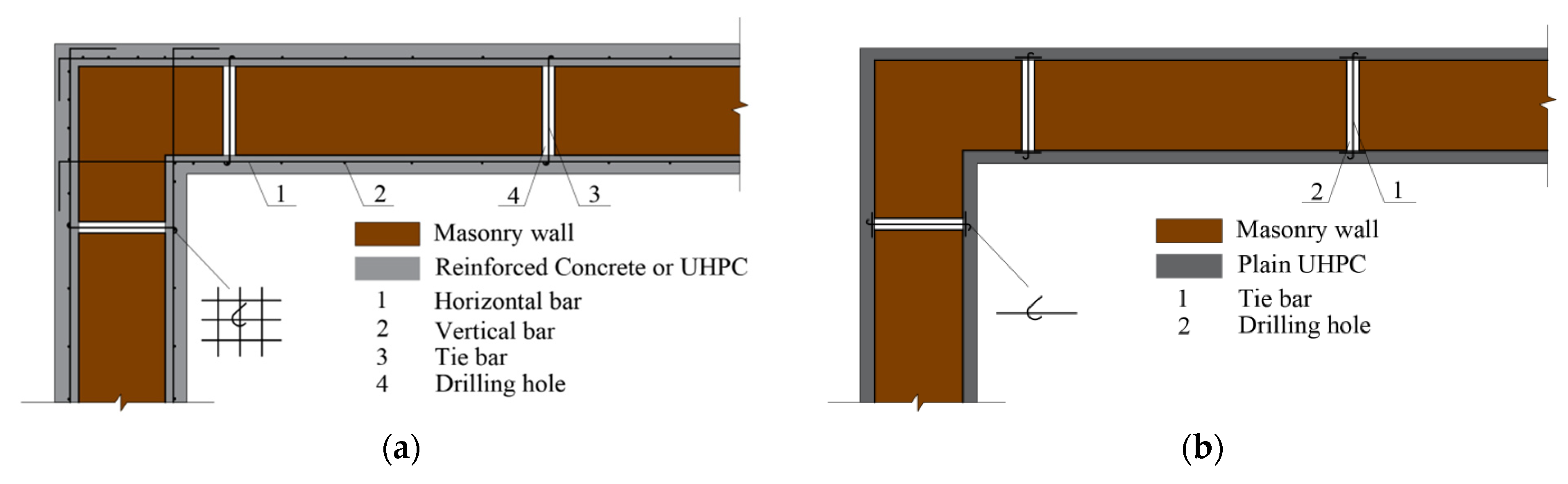
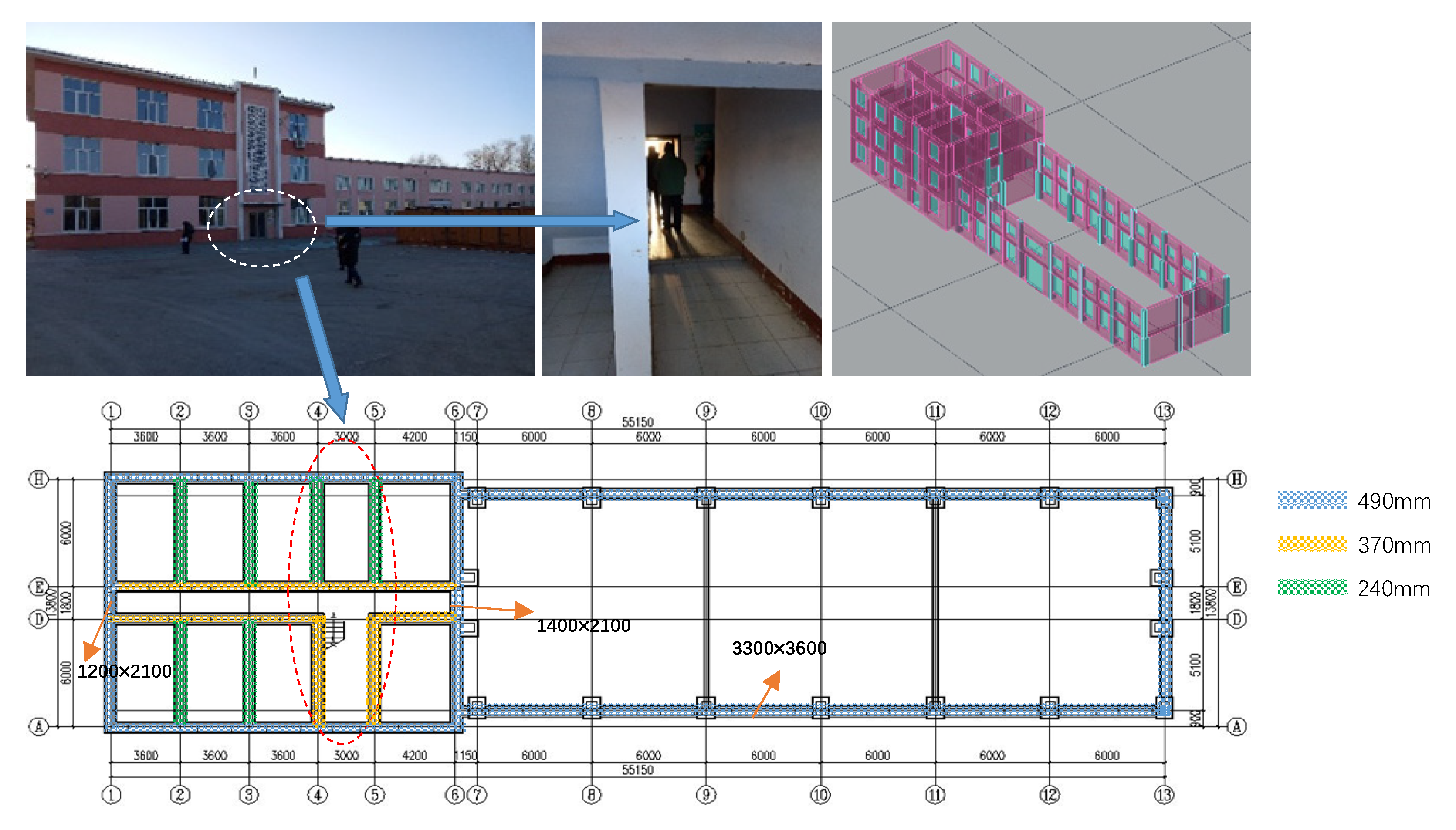
2.1. Description of Existing Masonry Structure Strengthening

Figure 1 shows the double-sided RC layers or UHPC layers, with and without rebars for strengthening masonry walls at a corner. Figure 2 shows the double-sided RC or UHPC layers with and without rebars for strengthening masonry walls at a T-wall joint. For a double-sided corner wall, the use of double-sided strengthening layers with steel ties and enclosure enhancement methods is recommended.
This article uses the PKPM v5.2 software developed by the China Academy of Building Research, a large-scale comprehensive CAD system for construction engineering. PKPM v5.2, also known as the plane mesh method, is applicable to stress analysis of various types of structures and can accurately simulate the stress behavior of structures under external loads. This software has been widely used in the Chinese construction industry. PKPM v5.2 is suitable for various types of structures, including masonry structure modules such as ordinary brick and concrete structures, bottom frame structures, concrete hollow block structures, reinforced masonry structures, and more. The PK module itself provides finite element structural calculation capabilities for planar bar systems, allowing users to input the model and load, including basic information such as axis, wall thickness, connecting beams, plate thickness, structural concrete columns, material design parameters, and other relevant details.

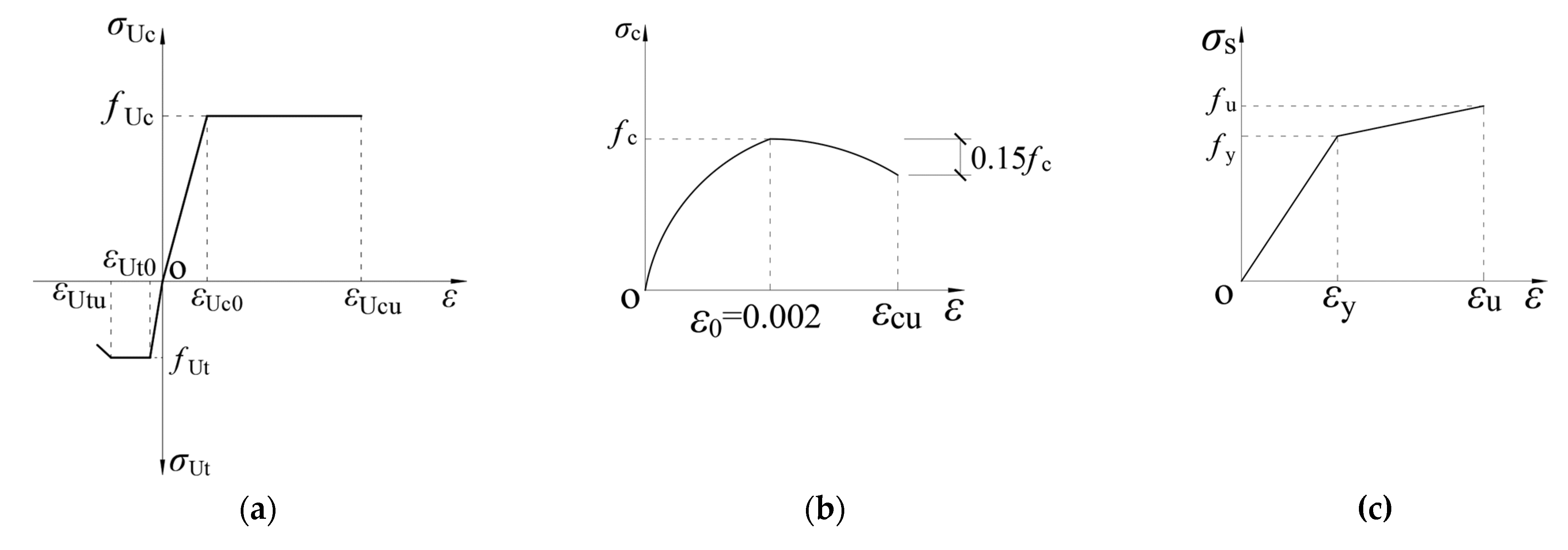
2.2. Material Properties and Stress–Strain Relationships

The masonry wall was strengthened using a double-sided enhancement method with C30 concrete and UHC150/UHT4.2 (i.e., compressive and tensile strength grade of UHPC). The materials’ properties are shown in Table 1.
The stress–strain relationship of UHPC is shown in Figure 3a. For the design constitutive model, the tensile elastic limit strain (εUt0) of UHT4.2 is 66 με, and the ultimate tensile strain (εUtu) is 1000 με. The compressive elastic limit strain (εUc0) of UHC150 is 1566 με, and ultimate compressive strain (εUcu) is 4000 με. The Hognestad model is used for C30 concrete, where the compressive elastic limit strain (ε0) is 2000 με, and the ultimate compressive strain (εcu) is 3800 με. HRB400-grade steel was used for reinforcing bars, with a design yield strength of 360 MPa. The stress–strain relationships of the concrete and reinforcing bars are shown in Figure 3b and Figure 3c, respectively.

2.3. Modeling Methodology and Load Cases

Figure 4 shows an existing masonry building. The thickness of the external masonry walls was 490 mm, while the thickness of the internal walls was either 370 mm or 240 mm, and the story height was 3600 mm. In masonry structures, severe earthquake damage often occurs at the internal and external walls of the stairwell on the first floor. In this study, the load resistance characteristics of the masonry walls before and after enhancement were investigated. Before earthquake damage, the strength grade of the brick was assumed to be MU7.5 (i.e., compressive strength = 7.5 MPa), and the mortar strength level was M5 (i.e., compressive strength = 5.0 MPa), resulting in a compressive strength of 1.335 MPa for the masonry structure (i.e., brick-and-mortar) [3]. MU5 is the minimum brick strength grade according to current codes, while M0 refers to the complete loss of strength of mortar. After earthquake damage, the strength grade of the brick was assumed to be MU5, and the strength grade of the mortar was close to zero, resulting in a compressive strength of 0.55 MPa for the masonry structure. This assumption was used as the minimum condition after considering historical environmental and seismic effects, and the enhancement analysis based on this assumption was conducted as a conservative analysis result to improve the enhancement performance of the weakest brick masonry structure.
The basic wind load is 0.4 kN/m2, the basic snow load is 0.2 kN/m2, and the roof load is 0.5 kN/m2. The live loads for the office, bathroom, and stairwell are 2.0 kN/m2, 2.5 kN/m2, and 3.5 kN/m2, respectively. For an input fortification intensity of 8 degrees, the fundamental design seismic acceleration value is 0.20 g, and the site characteristic period is 0.45 s. The design earthquake group I, the building structure safety grade II, and the design service life of 30 years were considered in the existing masonry building.
A pseudo-static method, also known as the Base Shear Force Method or Equivalent Lateral Force Procedure [24] or Lateral Force Method of Analysis [25], was adopted for masonry structures which estimates the horizontal seismic action of each floor and the shear force between floors. After the nonlinear static analysis, the axial compression resistance and shear resistance of both damaged and undamaged masonry walls were evaluated at each analysis step.
After strengthening, the stiffness and self-weight of the masonry walls are changed. A strengthening method utilizing a cement mortar layer with wire mesh was employed to enhance the strengthening of the UHPC layers. First, the thickness of the UHPC layers was converted into the equivalent thickness of cement mortar, based on the ratio of the elastic modulus of UHPC to that of cement mortar, which ensured consistency in stiffness. This approach is based on the fundamental principle of calculating internal forces in structural systems according to their stiffness distribution.

3. Results and Discussion

3.1. Structural Performance Before and After Earthquake

Here, R/S was defined as the ratio of the resistance of masonry structures to the corresponding load response. Table 2 shows the (R/S) values before and after earthquake damage. The analysis results show that the seismic performance of the masonry walls before earthquake damage was sufficient, showing R/S values greater than 1.0 for both compression and shear resistances. After the earthquake damage, the seismic performance of the masonry walls decreased by more than 50% on the first floor. A large number of the masonry walls on the first, second, and third floors did not meet the earthquake resistance requirements, as indicated by R/S values less than 1.0. It should be noted that only the R/S values for the masonry walls on the first floor, where the most significant damage occurred, are reported in Table 2.
In masonry structures, structural performance is governed by axial compression and shear resistance, which are considered the fundamental factors for damage inspection and safety evaluation in engineering practice.

3.2. Axial Compression Resistance

The axial compression resistance of the masonry structure strengthened by a RC layer (Equation (1)) and an UHPC layer (Equation (2)) can be estimated as follows:
N = φ com ( f m 0 A m 0 + α c f c A c + α cs f y A s )
N = φ com ( f m 0 A m 0 + α u f uc A u + α us f y A s )
where N is the design strength of the axial compression members after strengthening; φcom is the stability coefficient of the axial compression member, which can be adopted according to the height–thickness ratio and enhancement ratio of the section (i.e., 0.905–0.948 in this study); fm0 is the specified compressive strength of the original masonry wall; Am0 is the cross-sectional area of the original masonry wall; αc and αu are the coefficients related to the concrete and UHPC strength when a RC layer and UHPC layer are used for strengthening, respectively (i.e., αc = 0.80 and αu = 0.75, which was inferred from the value of the mortar strength utilization coefficient in reinforced brick masonry structures with steel mesh mortar); fc and fuc are the specified compressive strength of concrete and UHPC, respectively; Ac and Auc are the cross-sectional area of the RC layer and UHPC layer, respectively; αcs and αus are the coefficients related to the rebar strength at the RC layer and UHPC layer, respectively (i.e., αcs = 0.85 and αus = 0.80, which was inferred from the value of the rebar strength utilization coefficient in reinforced brick masonry structures with mortar); fy′ is the specified compressive strength of the vertical rebars in the RC layer and UHPC layer; and As′ is the cross-sectional area of the vertical rebars. It was noted that the coefficients for the UHPC layer were conservatively assumed to be the same as those of mortar because the coefficients for UHPC are not specified in the design code.

3.3. Shear Resistance

The shear resistance of masonry walls reinforced with a RC layer and an UHPC layer should be greater than the shear demand under earthquakes.
V V ME + V cs γ RE
V V ME + V sj γ RE
where V is the design shear force of the masonry wall under earthquake load; γRE is the seismic adjustment coefficient of shear capacity (=0.85 and 0.9 in Equations (3) and (4), respectively, according to GB50702-2011 [3]); VME is the shear resistance of the original masonry wall, which was calculated from GB 50003-2011 [26]; and Vcs and Vsj are the shear resistance provided by the RC layer or UHPC layer, respectively, which can be calculated from GB50702-2011 [3]. The first term of Equation (7) refers to the strength utilization coefficient of mortar reinforced with steel wire mesh, primarily considering the characteristics of UHPC mortar material. The second term adopts the rebar strength utilization coefficient for reinforced steel bars in the reinforced concrete surface layer enhancement, primarily considering that reinforcement steel bars are used in the UHPC enhancing layer instead of steel wire mesh.
V M E = f v + α μ σ 0 A
V cs = 0.44 α c f t b h + 0.8 α s f y A s ( h / s )
V sj = 0.02 f uc b h + 0.8 α s f y A s ( h / s )
where fv is the design shear stress of the existing masonry wall; α is the coefficient related to masonry brick type (=0.64 in this study); μ is the coefficient related to the shear–compression interaction (=0.178 in this study); σ0 is the average compressive stress of horizontal section generated by the design value of permanent load (=0.438 to 0.539 N/mm2 in this study); A is the shear resistant area; αc is the coefficients related to the masonry brick type (=0.80) [3]; ft is the specified tensile strength of concrete; b is the thickness of the RC layer (e.g., for double-sided cases, the sum of the thicknesses was taken); h is the horizontal length of the wall; αs is the coefficient related to the strength reduction of transverse enhancement under earthquake (=0.9 according to GB50702-2011 [3]); fy is the specified yield strength of the transverse reinforcement; As is the cross-sectional area of the transverse reinforcement; and s is the spacing of transverse reinforcement.

3.4. Influence of UHPC Layer Thickness and Rebar Content

In damaged masonry walls, the non-dimensional resistance ratio (Rr) was defined as the resistance provided by the strengthening RC or UHPC layers to the existing damaged masonry wall.
R r = f r t r + f rs , y t rs f m t m
The non-dimensional improvement ratio (ηN) was defined as the relative increase in the compression resistance of the damaged masonry wall resulting from strengthening.
η N = R / S n , r R / S n , d R / S n , d
where fr and fm are the specified compressive strength of the double-sided strengthening material and existing masonry wall after earthquake damage, respectively (i.e., fr = 14.3 MPa for concrete and 71.0 MPa for UHPC, and fm = 0.55 MPa for the masonry wall in this study); tr and tm are the thicknesses of the double-sided strengthening layers and the existing masonry wall, respectively (i.e., tr = 2 × (20 or 30) mm, and tm = 370 or 490 mm in this study); and frs,y and trs are the specified yield strength of the rebars in the double-sided strengthening layers and the equivalent thickness of the rebars within a unit length of 1000 mm, respectively (i.e., frs,y = 360 MPa and trs = Ars/1000 = 0 mm or 0.785 mm in this study).
Table 3 shows the axial compression resistance of three representative masonry walls reinforced with double-sided RC and UHPC layers (i.e., external walls 1-HE and H-78 and stair wall 4-DA). For the strengthening of damaged masonry walls, RC and UHPC strengthening layers of at least 30 mm in thickness are required due to cover concrete thickness. As shown in Table 3, the improvement ratio (ηN) of the axial compression resistance of walls 4-DA, 1-HE, and H-78 reinforced with 30 mm thick double-sided plain UHPC layers (without rebars) was 3.44, 3.65, and 3.58 times that of the corresponding walls reinforced with the double-sided RC layers (i.e., 17.9/5.2, 11.3/3.1, and 12.9/3.6), respectively. This result indicates that the compressive resistance of the damaged masonry walls reinforced with 30 mm thick double-sided plain UHPC layers was about 250% greater than that of the corresponding walls reinforced with double-sided RC layers. When the thickness of the plain UHPC layers was decreased to 20 mm, the compressive resistance of the damaged masonry walls was about 135% greater than that of the corresponding walls reinforced with 30 mm thick double-sided RC layers.

3.5. Regression Analysis of Strengthening Parameters

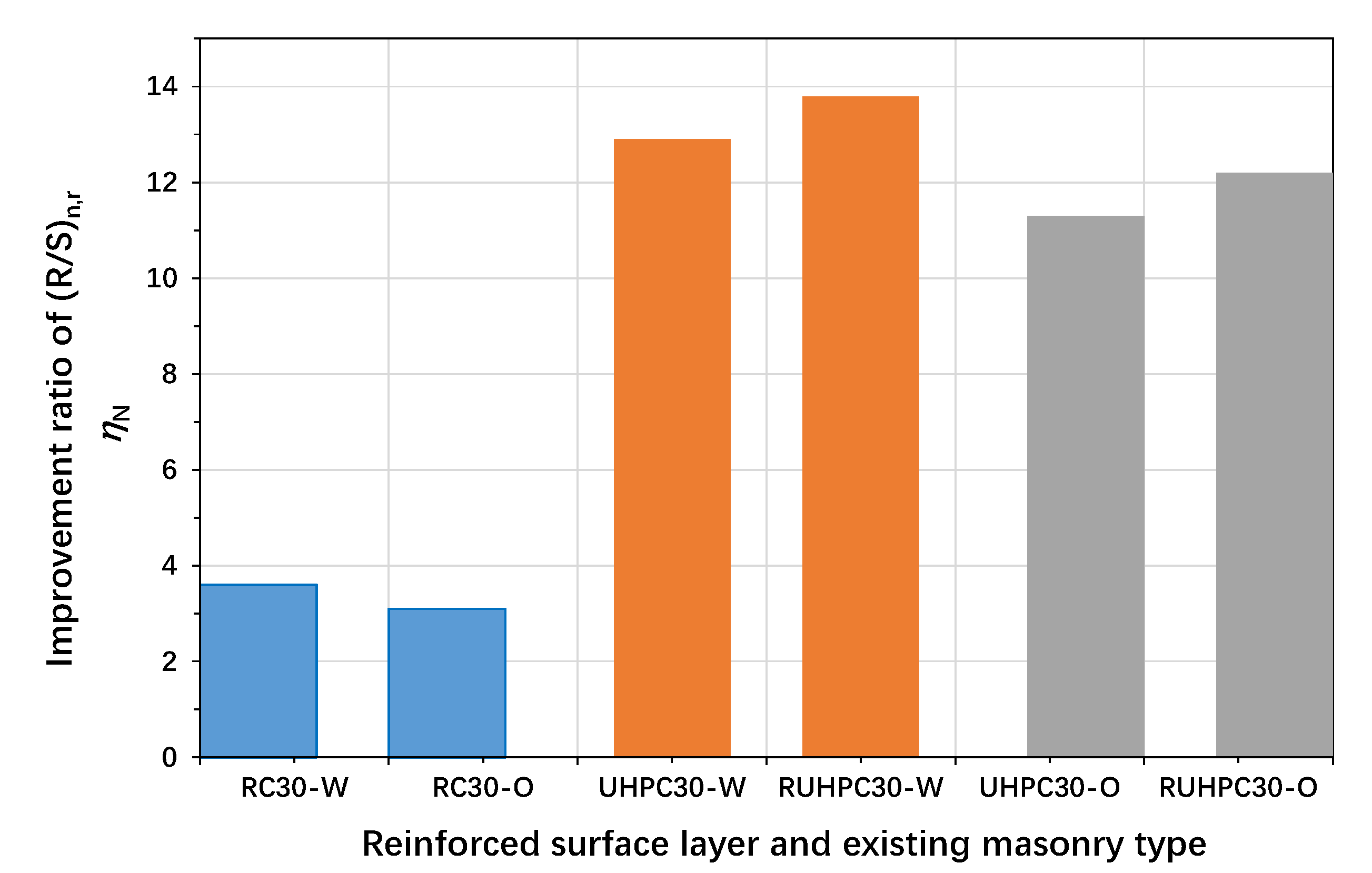
3.5.1. Variations in the Ratio of Compression Resistance

The influence of dimensionless enhancement parameters on the performance of structural strengthening will provide a basis for designing effective strengthening schemes. Figure 5 shows the variations in the ratio of compression resistance to demand of the strengthened masonry walls ((R/S)n,r) and the improvement ratio (ηN) following the resistance ratio (Rr) of the enhancement materials to the existing damaged masonry wall under axial compression. As the resistance ratio (Rr) increased, the ratio of compression resistance to the demand of the retrofitted masonry walls significantly increased (Figure 5a). The improvement ratio of (ηN) of the retrofitted masonry wall with window openings (H-78) was slightly greater than that of the counterpart retrofitted masonry wall without window openings (1-HE) (Figure 5b). This was because the resistance of the wall with window openings before strengthening was relatively low. Under the same resistance ratio (Rr), the improvement ratio (ηN) of the retrofitted masonry wall with a thickness of 370 mm (4-DA) was slightly greater than that of the counterpart retrofitted masonry wall with a thickness of 490 mm (1-HE) (Figure 5b). This was because the wall with a smaller thickness developed less resistance.
To evaluate the relationship between Rr and ηN, several additional data groups from this masonry structure were included, considering various rebar ratios (i.e., 0–0.366%) and RC and UHPC layer design strengths (i.e., 14.3–19.1 MPa and 61–71 MPa, respectively) as shown in Table 4, in which ηN is the non-dimensional improvement ratio and Rr is the non-dimensional resistance ratio. Based on the analysis results, the regression relationship between parameters ηN and Rr can be approximately defined as follows (Figure 5c):
η N = 0.83 R r 0.26

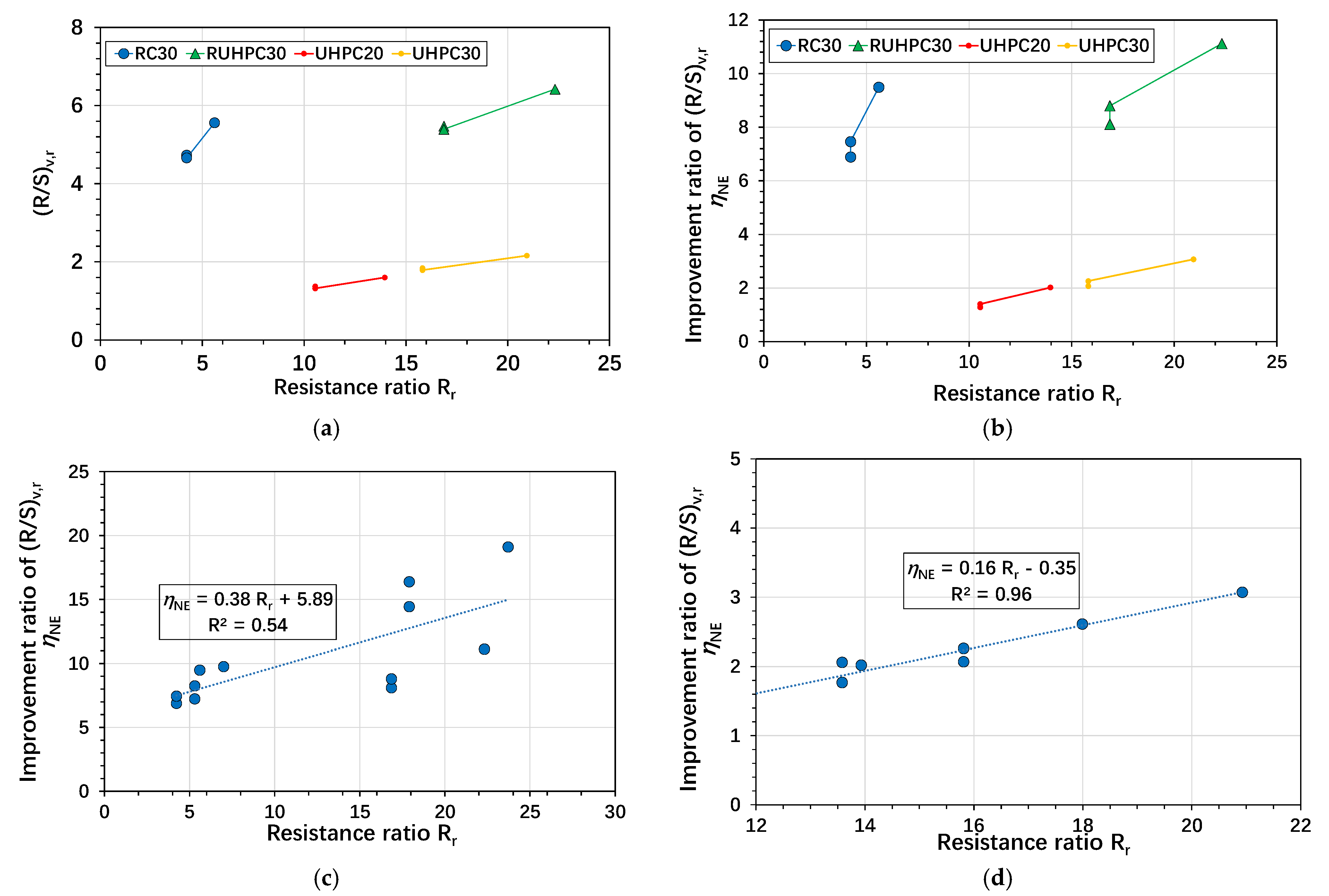
3.5.2. Non-Dimensional Improvement Ratio of Shear Resistance

In the damaged masonry wall, the non-dimensional improvement ratio (ηNE) of the shear resistance of the damaged masonry wall due to strengthening was defined as follows:
η NE = R / S v , r R / S v , d R / S v , d
where (R/S)v,r and (R/S)v,d are the ratios of shear resistance to demand for the strengthened masonry walls and the existing damaged masonry walls after earthquake damage, respectively.
Table 5 shows the shear resistance of three representative masonry walls reinforced with double-sided RC and UHPC layers (i.e., external walls 1-HE and H-78 and stair wall 4-DA). Compared to the masonry walls reinforced with double-sided RC layers, the shear resistance of the walls reinforced with 20 or 30 mm thick plain double-sided UHPC layers decreased by 61–72%, but still met the enhancement requirements. When RUHPC layers (i.e., UHPC layers with rebars) of 30 mm thickness were used for double-sided enhancement, the ratio of shear resistance to demand ((R/S)v,r) was 300% and 200% greater than that of the corresponding masonry walls reinforced with 20 mm and 30 mm thick plain UHPC layers, respectively. In particular, for walls 4-DA, 1-HE, and H-78 reinforced with 30 mm thick double-sided RUHPC layers, the ratio of shear resistance to shear demand ((R/S)v,r) was 1.16 times that of the corresponding masonry walls reinforced with double-sided RC layers. The improvement ratio (ηNE) of the masonry walls reinforced with double-sided RC layers and UHPC layers with rebars was 209–292% greater than that of the corresponding masonry walls strengthened with plain UHPC layers due to the contribution of shear reinforcement to the shear resistance.
Here, the non-dimensional n was defined as the axial compression ratio, i.e., the ratio of the axial compressive internal force to the axial compressive bearing capacity. As shown in Table 5, the non-dimensional value n of the masonry walls reinforced with 30 mm thick double-sided plain UHPC layers decreased by about 70%, compared to the corresponding masonry walls reinforced with double-sided RC layers. When the thickness of the plain UHPC layers decreased to 20 mm, the value of n decreased by about 60%, compared to the corresponding masonry walls reinforced with double-sided RC layers. Thus, the use of UHPC layers can effectively decrease n due to significantly improved load resistance.

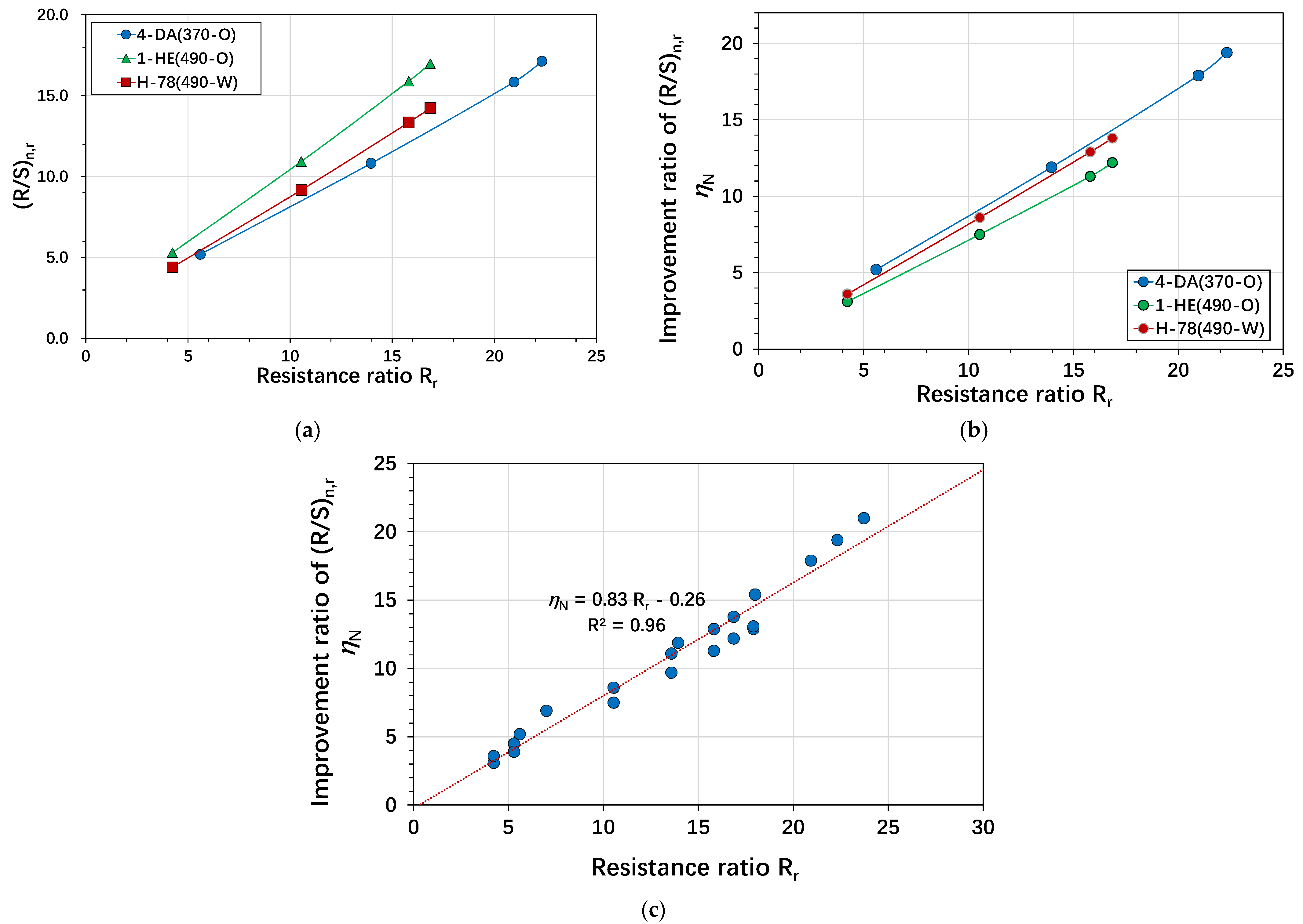
3.5.3. Effect of the Non-Dimensional Resistance Ratio

Figure 6 shows the effect of the non-dimensional resistance ratio (Rr) of the enhancement material on the existing damaged masonry walls on the shear resistance. As the non-dimensional resistance ratio (Rr) increased, the ratio of shear resistance to demand ((R/S)v,r) of the retrofitted masonry walls significantly increased for walls strengthened by the double-sided RC layers and RUHPC layers (i.e., RC30 and RUHPC30 in Figure 6a). In contrast, the ratio (R/S)v,r of the masonry walls reinforced with double-sided plain UHPC layers increased slightly with the increase in Rr. A similar trend was observed in the improvement ratio (ηNE) (Figure 6b). Thus, it was necessary to configure enhancement materials to improve the shear resistance effectively.
To evaluate the relationship between Rr and ηNE, several additional data groups for this masonry structure were additionally included, considering various rebar ratios (i.e., 0–0.366%), and the design strength of RC and UHPC layers (i.e., 14.3–19.1 MPa and 61–71 MPa, respectively) (Table 6). Based on the analysis results, the regression relationship between the improvement ratio (ηNE) and resistance ratio (Rr) for walls reinforced with RC layers or RUHPC layers can be approximately defined as follows (Figure 6c):
η NE = 0.38 R r + 5.89
Based on the analysis results, the regression relationship between the improvement ratio (ηNE) and resistance ratio (Rr) for walls reinforced with plain UHPC layers can be approximately defined as follows (Figure 6d):
η NE = 0.16 R r 0.35

4. Comparison of Strengthening Techniques

4.1. RC vs. UHPC Strengthening Performance

The amplitude of the wall resistance effect ratio with different materials and corresponding strengthening thicknesses may provide a concept for selecting appropriate materials and reinforcement thicknesses for strengthening designs, targeting the desired resistance effect ratio in the design stage of structural strengthening schemes. Figure 7 compares the non-dimensional improvement ratio (ηN) of the axial resistance of the damaged masonry walls based on the strengthening details. In this figure, the letters “W” and “O” denote walls with and without windows, respectively. The improvement of axial resistance when strengthened by UHPC layers was greater than that when strengthened by RC layers. Figure 8 compares the non-dimensional improvement ratios (ηNE) of the shear resistance of the damaged masonry walls based on the strengthening details. The shear resistance of the damaged masonry walls was improved by strengthening, and the use of double-sided RUHPC layers with a thickness of 30 mm significantly improved the shear resistance.

4.2. Cost-Effectiveness and Design Coniderations

Although UHPC was strengthened and toughened by steel fiber and the shear resistance of the material was significantly improved, from the perspective of seismic retrofit, the design thickness of UHPC layers for surface enhancement of existing masonry structures can be appropriately reduced. Furthermore, it was necessary to design the rebar according to the current specifications. The use of double-sided RUHPC layers with a thickness of 30 mm significantly improved the axial resistance; however, compared to double-sided plain UHPC layers, the improvement was not substantial. Thus, when UHPC was used as the surface enhancement of existing masonry structures, no rebar design would likely be cost-effective in practice.

5. Conclusions

In the present study, the seismic and strengthening performance of a building with damaged masonry walls under earthquake load were investigated using ultra-high-performance concrete. According to the comparative analysis results with conventional strengthening material, the findings can be summarized as follows:
(1)
Damaged masonry walls can be retrofitted with plain UHPC layers, and the thickness of the UHPC layers can be appropriately reduced according to design requirements. For typical cases, the compressive resistance of the damaged masonry walls strengthened with 30 mm thick double-sided plain UHPC layers was about 3.0 times that of the corresponding masonry walls strengthened with 30 mm thick double-sided RC layers. When the thickness of the plain UHPC layers was reduced to 20 mm, the compressive resistance of the strengthened masonry walls decreased to about 2.0 times that of the corresponding masonry walls reinforced with 30 mm thick double-sided RC layers. The design thickness of UHPC has a significant impact on the compressive resistance of the existing masonry structures.
(2)
The seismic performance of existing brick masonry structures strengthened with UHPC shows a non-linear increase as the thickness of the UHPC layer increases. For typical cases, the axial compression ratio of the masonry walls can be reduced by approximately 60–70% when double-sided plain UHPC layers are used for strengthening. From the perspective of seismic strengthening, the seismic performance of the damaged masonry walls can be improved by about 150%, 250%, and 930% when 20 mm thick double-sided plain UHPC layers, 30 mm thick double-sided plain UHPC layers, and 30 mm thick double-sided RUHPC layers are used for strengthening, respectively.
(3)
This article proposes a resistance ratio strengthening parameter and examines its influence on structural behavior. Generally, the regression analysis results showed that the ratio of axial resistance to shear resistance increased linearly with the increase in the resistance ratio. In particular, this relationship was evident in the enhancement effect of axial resistance. To effectively increase the shear resistance, it is recommended to use RC or RUHPC layers with reinforcement.
(4)
When the axial compression and shear demands are relatively low, plain UHPC layers can be used without a significant increase in wall thickness. For retrofitting the typical damaged masonry walls described in this paper, the use of 30 mm thick reinforced UHPC layers significantly improved the structural performance. Subsequently, the use of plain UHPC layers provided satisfactory structural performance for the strengthened masonry walls without requiring a minimum thickness.
Research perspectives: This article is based on the structural design software PKPM v5.2 for overall structural analysis. The obtained UHPC enhancement parameters are used to analyze the structural capacity margin, providing a reference for selecting structural strengthening schemes under different enhancement target values. The equivalent modulus method of mortar strengthening surface layer is used to achieve it. In the future, further research could be conducted on modifying the performance of the enhancement interface and developing UHPC enhancement surface layer material modules based on PKPM v5.2 in order to facilitate the design of UHPC enhancement engineering.

Author Contributions

Conceptualization, R.W. and W.W.; methodology, X.W. and Y.L.; software, Y.Z.; validation, X.W., D.W. and F.Q.; formal analysis, Y.Z.; investigation, R.W. and X.W.; resources, R.W. and W.W.; data curation, Q.W.; writing—original draft preparation, Y.Z.; writing—review and editing, X.W.; visualization, Y.Z.; supervision, X.W.; project administration, Q.W.; funding acquisition, Q.W. All authors have read and agreed to the published version of the manuscript.

Funding

This research was funded by the National Natural Science Foundation of China with the funding number 52178195 and Heilongjiang Province’s Open Competition Science and Technology Research Project with the funding number 2023ZXJ05C01.

Data Availability Statement

The original contributions presented in this study are included in the article. Further inquiries can be directed to the corresponding authors.

Conflicts of Interest

Authors Rui Wang, Wei Wang and Quan Wen were employed by the company Heilongjiang Construction Group Co., Ltd. Author Rui Wang was employed by the company Heilongjiang Wujian Construction Engineering Co., Ltd. Author Ya Lu was employed by the company Jiangxi Building Materials Research and Design Institute Co., Ltd. Author Faqiang Qiu was employed by the company Jian Yan Test Group Company Limited. The remaining authors declare that the research was conducted in the absence of any commercial or financial relationships that could be construed as a potential conflict of interest.

References

  1. GB50011-2010[S]; Code for Seismic Design of Buildings. China Architecture & Building Press: Beijing, China, 2016. (In Chinese)
  2. GB50702-2011[S]; Code for Design of Strengthening Masonry Structures. China Architecture & Building Press: Beijing, China, 2011. (In Chinese)
  3. Orlowsky, J.; Beßling, M.; Kryzhanovskyi, V. Prospects for the Use of Textile-Reinforced Concrete in Buildings and Structures Maintenance. Buildings 2023, 13, 189. [Google Scholar] [CrossRef]
  4. Sayin, E.; Calayir, Y. Comparison of linear and non-linear earthquake response of masonry walls. Comput. Concr. 2015, 16, 17–35. [Google Scholar] [CrossRef]
  5. Karaca, Z.; Turkeli, E.; Pergel, S. Seismic assessment of historical masonry structures: The case of Amasya Tashan. Comput. Concr. 2017, 20, 409–418. [Google Scholar]
  6. Laib, S.; Meftah, S.A.; Tounsi, A. Vibration and damping characteristics of the masonry wall strengthened with bonded fibre composite patch with viscoelastic adhesive layer. Comput. Concr. 2021, 27, 253–268. [Google Scholar]
  7. Koksal, H.O.; Jafarov, O.; Karakoc, C. Computational material modeling of masonry walls strengthened with fiber reinforced polymers. Struct. Eng. Mech. 2013, 48, 737–755. [Google Scholar] [CrossRef]
  8. Mercedes, L.; Bernat-Maso, E.; Gil, L. Numerical simulation of masonry walls strengthened with vegetal fabric reinforced cementitious matrix (FRCM) composites and subjected to cyclic loads. Structures 2022, 35, 1232–1242. [Google Scholar] [CrossRef]
  9. Deng, M.; Dong, Z.; Ma, P. Cyclic loading tests of flexural-failure dominant URM walls strengthened with engineered cementitious composite. Eng. Struct. 2019, 194, 173–182. [Google Scholar] [CrossRef]
  10. Choi, H.K.; Bae, B.I.; Choi, C.S. Lateral resistance of unreinforced masonry walls strengthened with engineered cementitious composite. Int. J. Civ. Eng. 2016, 14, 411–424. [Google Scholar] [CrossRef]
  11. Bui, T.L.; Larbi, A.S.; Reboul, N.; Ferrier, E. Shear behaviour of masonry walls strengthened by external bonded FRP and TRC. Compos. Struct. 2015, 132, 923–932. [Google Scholar] [CrossRef]
  12. Sharbatdar, M.K.; Tajari, A. Experimental in-plane seismic strengthening of masonry infilled reinforced concrete frames by engineered cementitious composites (ECC). Constr. Build. Mater. 2021, 293, 123529. [Google Scholar] [CrossRef]
  13. Gul, A.; Alam, B.; Khan, I.U.; Shah, S.A.A.; Khan, S.W.; Shahzada, K. Improving seismic capacity of dry stacked interlocking masonry structurethrough confinement at corners. Soil Dyn. Earthq. Eng. 2023, 165, 107710. [Google Scholar] [CrossRef]
  14. Tao, Y.; Xu, Z.-D.; Wei, Y.; Miao, C.; Ji, B. Energy-based damage assessment method for masonry walls under seismicand fire loads. Eng. Struct. 2025, 322, 119152. [Google Scholar] [CrossRef]
  15. Szabó, S.; Funari, M.F.; Lourenço, P.B. Masonry patterns’ influence on the damage assessment of URM walls. Current and future trends. Dev. Built Environ. 2023, 13, 100119. [Google Scholar] [CrossRef]
  16. Hung, C.-C.; Dai, Y.-X.; Yen, C.-H.; Mosalam, K.M. Comparative studies on in-plane shear behavior of masonrywallettes retrofitted with mortar, UHPC, and ECC ferrocement: Shotcrete and prefabricated panels. Case Stud. Constr. Mater. 2024, 21, e03801. [Google Scholar] [CrossRef]
  17. T/CBMF 37-2018/T/CCPA 7-2018 [S]; China Building Material Association: Fundamental Characteristics and Test Methods of Ultra-High Performance Concrete. China Architecture Industry Publishing House: Beijing, China, 2018.
  18. Peng, B.; Wei, S.; Long, L.; Zheng, Q.; Ma, Y.; Chen, L. Experimental Investigation on the Performance of Historical Squat Masonry Walls Strengthened by UHPC and Reinforced Polymer Mortar Layers. Appl. Sci. 2019, 9, 2096. [Google Scholar] [CrossRef]
  19. Dong, F.; Wang, H.; Jiang, F.; Xing, Q.; Yu, J. In-plane shear behavior of masonry panels strengthened with ultra-high ductile concrete (UHDC). Eng. Struct. 2022, 252, 113609. [Google Scholar] [CrossRef]
  20. Wang, X.; Li, S.; Wu, Z.; Bu, F.; Wang, F. Experimental study on seismic strengthening of confined masonry walls using RPC. Adv. Mater. Sci. Eng. 2019, 2019, 5095120. [Google Scholar] [CrossRef]
  21. Madhavi, K.; Vinay, G.N.; Devi, M.V.R.; Basutkar, S. Shear behavior of brick masonry strengthened with jute fiber reinforced composite. Mater. Today Proc. 2021, 46, 4746–4751. [Google Scholar] [CrossRef]
  22. Meriggi, P.; De Santis, S.; Fares, S.; de Felice, G. Design of the shear strengthening of masonry walls with fabric reinforced cementitious matrix. Constr. Build. Mater. 2021, 279, 122452. [Google Scholar] [CrossRef]
  23. Shafighfard, T.; Kazemi, F.; Asgarkhani, N.; Yoo, D.-Y. Machine-learning methods for estimating compressive strength ofhigh-performance alkali-activated concrete. Eng. Appl. Artif. Intell. 2024, 136, 109053. [Google Scholar] [CrossRef]
  24. ASCE/SEI7-10; Minimum Design Loads for Buildings and Other Structures. American Society of Civil Engineers: Reston, VA, USA, 2010.
  25. European Committee for Standardization. Eurocode 8: Design of Structures for Earthquake Resistance-Part 1:General Rules, Seismic Actions and Rules for Buildings; European Committee for Standardization: Brussels, Belgium, 2004. [Google Scholar]
  26. GB50003-2011 [S]; Code for Design of Masonry Structures. China Architecture & Building Press: Beijing, China, 2011. (In Chinese)
Figure 1. Double-sided enhancement at corner masonry wall: (a) reinforced concrete (RC) or reinforced UHPC (RUHPC); (b) plain UHPC.
Buildings 15 02082 g001
Figure 2. Double-sided enhancement at T-wall connection: (a) reinforced concrete or reinforced UHPC (RUHPC); (b) plain UHPC.
Buildings 15 02082 g002
Figure 3. Simplified stress–strain relationships of materials under uniaxial tension and compression: (a) UHPC; (b) concrete; (c) reinforcing bars.
Buildings 15 02082 g003
Figure 4. Examples and model drawings of existing masonry structure (mm). Note: for E-1~6 and D-1~6, the size of the door is 1000 mm × 2100 mm; for H-1~6 and A-1~6, the size of the window is 1800 mm × 2100 mm; for H-7~13 and A-7~13, the size of the window is 1800 mm × 2400 mm; other hole sizes are shown in the figure.
Buildings 15 02082 g004
Figure 5. Compression resistance of the masonry walls with various retrofitting details: (a) variation of the ratio of compression resistance to demand (R/S)n,r with resistance ratio Rr; (b) variation of improvement ratio ηN with resistance ratio Rr; (c) regression analysis between improvement ratio ηN and resistance ratio Rr.
Buildings 15 02082 g005
Figure 6. Shear resistance of the masonry walls with various retrofitting details: (a) variation of the ratio of shear resistance to demand (R/S)v,r with resistance ratio Rrs; (b) variation of the improvement ratio ηNE in accordance with resistance ratio Rr; (c) regression analysis between the improvement ratio ηNE and resistance ratio Rr in the masonry walls reinforced by RC layers or RUHPC layers; (d) regression analysis between the improvement ratio ηNE and resistance ratio Rr in the masonry walls reinforced with plain UHPC layers.
Buildings 15 02082 g006
Figure 7. Comparison of axial resistance enhancement.
Buildings 15 02082 g007
Figure 8. Comparison of shear resistance enhancement.
Buildings 15 02082 g008
Table 1. Material properties.
MaterialsDesign Compressive Strength/MPaDesign Tensile Strength/MPaDensity/kg/m3Elastic Modulus/GPaPoisson’s Ratio
UHC150/UHT4.2712.982500450.18
C3014.31.432400300.18
Table 2. Resistance-to-load demand ratio of the masonry walls on the first floor.
Masonry Walls1-HE1-DAE-23E-34E-45E-56
Wall thickness (mm)490490370370370370
Before earthquake damageAxial load resistance (R/S)3.003.031.802.311.7513.40
Shear resistance (R/S)1.231.221.301.201.791.14
After earthquake damageAxial load resistance (R/S)1.291.300.771.000.7412.53
Shear resistance (R/S)0.550.540.610.550.840.51
Note: 1-HE denotes the wall located on axis 1 and between axes H and E; and E-23 denotes the wall located on axis E and between axes 2 and 3. R/S is the ratio of the resistance of masonry structures to the corresponding load response.
Table 3. Axial compression resistance according to retrofitting details.
Walls4-DA (370-O)1-HE (490-O)H-78 (490-W)
Original wall thickness (mm)370 490 490
Before earthquake damageAxial load resistance (×103 kN)2.57 3.79 0.713
Axial load demand (×103 kN)1.20 1.26 0.301
R/S2.15 3.00 2.37
After earthquake damageAxial load resistance (×103 kN)1.01 1.63 0.289
Axial load demand (×103 kN)1.20 1.26 0.301
(R/S)n,d0.841.29 0.96
Double-sided RC layers with 30 mm thicknessAxial load resistance (×103 kN)6.246.67 1.33
Axial load demand (×103 kN)1.20 1.26 0.301
(R/S)n,r5.2 5.3 4.4
Resistance ratio (Rr)5.60 4.23 4.23
Improvement ratio (ηN)5.2 3.1 3.6
Double-sided UHPC layers with 20 mm thicknessAxial load resistance (×104 kN)1.30 1.38 0.276
Axial load demand (×103 kN)1.20 1.26 0.301
(R/S)n,r10.82 10.93 9.17
Resistance ratio (Rr)13.96 10.54 10.54
Improvement ratio (ηN)11.9 7.5 8.6
Double-sided UHPC layers with 30 mm thicknessAxial load resistance (×104 kN)1.90 2.01 0.402
Axial load demand (×103 kN)1.20 1.26 0.301
(R/S)n,r15.84 15.90 13.35
Resistance ratio (Rr)20.93 15.81 15.81
Improvement ratio (ηN)17.9 11.3 12.9
Double-sided RUHPC layers with 30 mm thicknessAxial load resistance (×104 kN)2.05 2.14 0.428
Axial load demand (×103 kN)1.20 1.26 0.301
(R/S)n,r17.12 16.97 14.24
Resistance ratio (Rr)22.32 16.86 16.86
Improvement ratio (ηN)19.4 12.2 13.8
Note: Here, (R/S)n,r and (R/S)n,d are the ratios of compression resistance to demand for the strengthened masonry walls and the existing damaged masonry walls after earthquake damage, respectively.
Table 4. Variation of ηN in accordance with Rr for various modification parameters.
RC Layer or UHPC Layer StrengthC40
(19.1 MPa)
C40
(19.1 MPa)
C40
(19.1 MPa)
UHC130
(61 MPa)
UHC130
(61 MPa)
UHC130
(61 MPa)
UHC150
(71 MPa)
UHC150
(71 MPa)
UHC150
(71 MPa)
rebar ratio0.183%0.143%0.143%0000.366%0.286%0.286%
wallH-781-HE4-DAH-781-HE4-DAH-781-HE4-DA
Rr5.30 5.30 7.00 13.58 13.58 17.99 17.90 17.90 23.71
ηN4.50 3.90 6.90 11.10 9.70 15.40 12.90 13.10 21.00
Note: ηN is the non-dimensional improvement ratio and Rr is the non-dimensional resistance ratio.
Table 5. Shear resistance according to retrofitting details.
Walls4-DA (370-O)1-HE (490-O)H-78 (490-W)
Before earthquake damage Shear resistance (×102 kN)3.42 4.46 0.917
Shear demand (×102 kN)2.95 3.630.700
R/S1.16 1.23 1.31
After earthquake damageShear resistance (×102 kN)1.56 1.99 0.420
Shear demand (×102 kN)2.95 3.63 0.700
(R/S)v,d0.53 0.55 0.60
Double-sided RC layers with 30 mm thicknessShear resistance (×103 kN)1.7681.7570.354
Shear demand (×103 kN)0.318 0.377 0.0748
(R/S)v,r5.56 4.66 4.73
Resistance ratio (Rr)5.60 4.234.23
Improvement ratio (ηNE)9.49 7.46 6.89
n0.192 0.189 0.225
Double-sided UHPC layers with 20 mm thicknessShear resistance (×102 kN)4.97 4.87 1.00
Shear demand (×102 kN)3.11 3.69 0.730
(R/S)v,r1.60 1.32 1.37
Resistance ratio (Rr)13.96 10.54 10.54
Improvement ratio (ηNE)2.02 1.40 1.28
n0.092 0.091 0.109
Double-sided UHPC layers with 30 mm thickness Shear resistance (×102 kN)6.87 6.76 1.38
Shear demand (×102 kN)3.18 3.77 0.748
(R/S)v,r2.16 1.79 1.84
Resistance ratio (Rr)20.93 15.81 15.81
Improvement ratio (ηNE)3.07 2.26 2.07
n0.0630.063 0.075
Double-sided RUHPC layers with 30 mm thickness Shear resistance (×103 kN)2.04 2.03 0.409
Shear demand (×103 kN)0.318 0.377 0.0748
(R/S)v,r6.42 5.39 5.47
Resistance ratio (Rr)22.32 16.86 16.86
Improvement ratio (ηNE)11.12 8.80 8.11
n0.0580.059 0.070
Note: Axial compression ratio n was defined as the ratio of the axial compression load to the axial compression resistance. (R/S)v,r and (R/S)v,d are the ratios of shear resistance to demand for the strengthened masonry walls and the existing damaged masonry walls after earthquake damage, respectively.
Table 6. Variation of ηNE in accordance with Rr for various modification parameters.
RC Layer or UHPC Layer StrengthC40
(19.1 MPa)
C40
(19.1 MPa)
C40
(19.1 MPa)
UHC130
(61 MPa)
UHC130
(61 MPa)
UHC130
(61 MPa)
UHC150
(71 MPa)
UHC150
(71 MPa)
UHC150
(71 MPa)
rebar ratio0.183%0.143%0.143%0000.366%0.286%0.286%
wallsH-781-HE4-DAH-781-HE4-DAH-781-HE4-DA
Rr5.30 5.30 7.00 13.58 13.58 17.99 17.90 17.90 23.71
ηN7.24 8.25 9.76 1.77 2.06 2.61 14.43 16.38 19.10
Note: ηN is the non-dimensional improvement ratio and Rr is the non-dimensional resistance ratio.
Disclaimer/Publisher’s Note: The statements, opinions and data contained in all publications are solely those of the individual author(s) and contributor(s) and not of MDPI and/or the editor(s). MDPI and/or the editor(s) disclaim responsibility for any injury to people or property resulting from any ideas, methods, instructions or products referred to in the content.

