

Performance of Deltabeam–CLT Composite Floors Under Human-Induced Vibration


Abstract
1. Introduction
2. Numerical Simulation of the Deltabeam–CLT Composite Floor System Under Human-Induced Loads
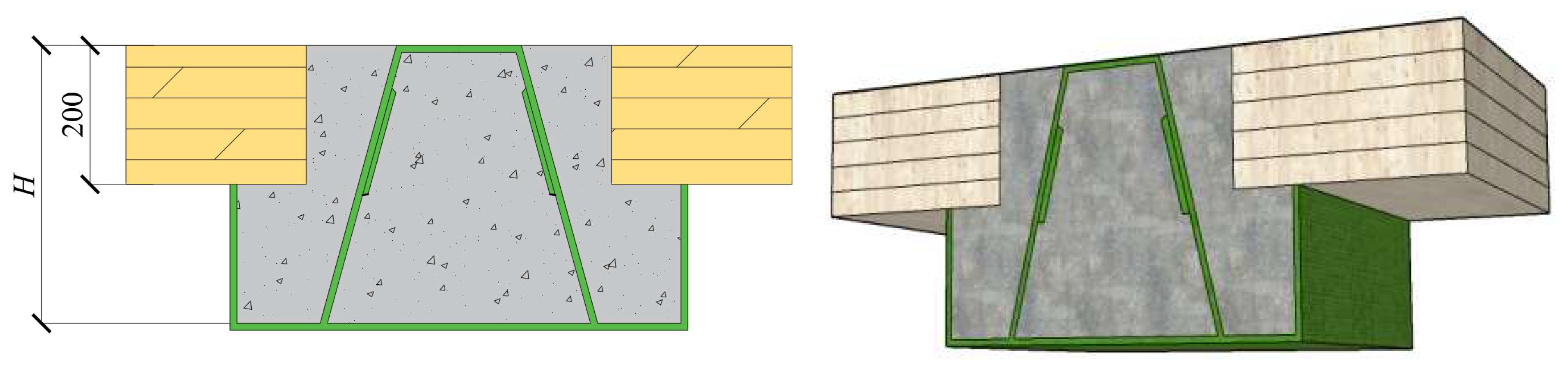
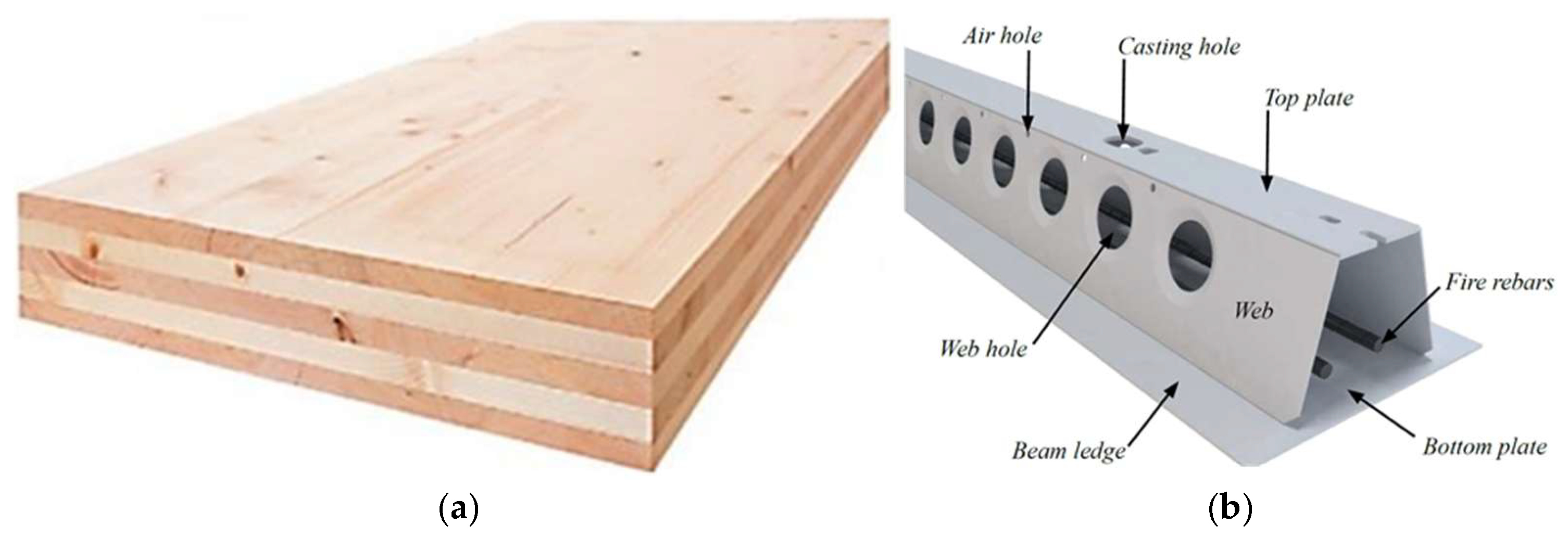
2.1. Material Properties and Floor Panel Information
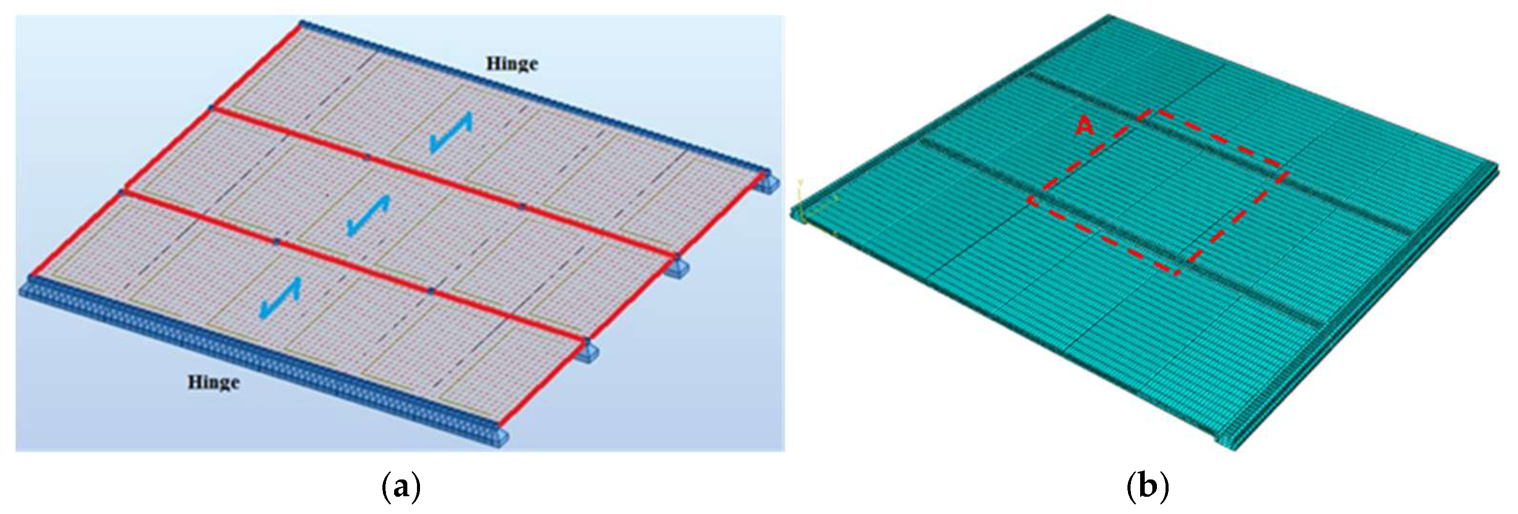
2.2. Finite Element Model Development
2.3. Modal Analysis
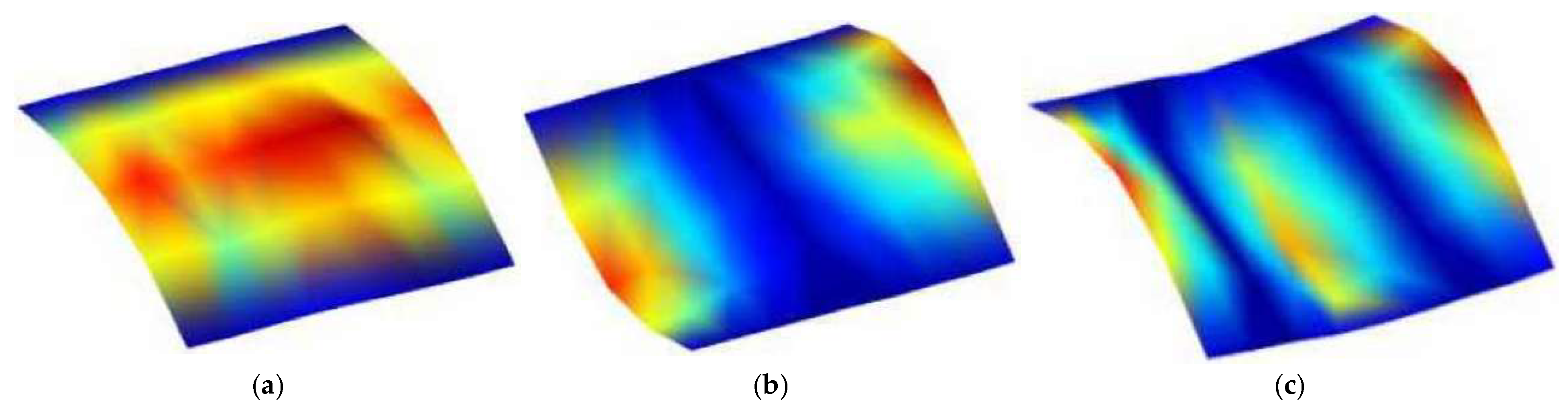
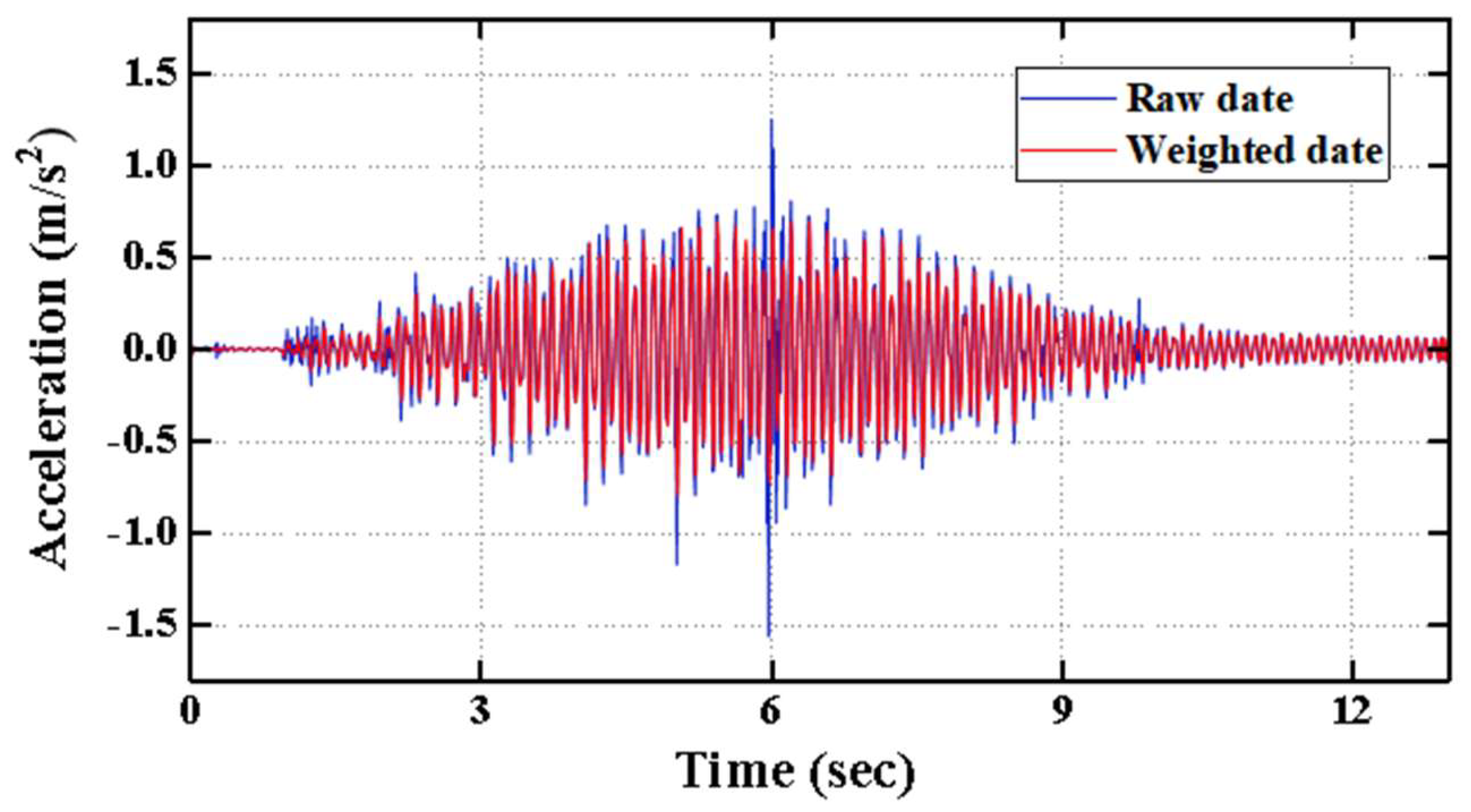
2.4. Model Validation
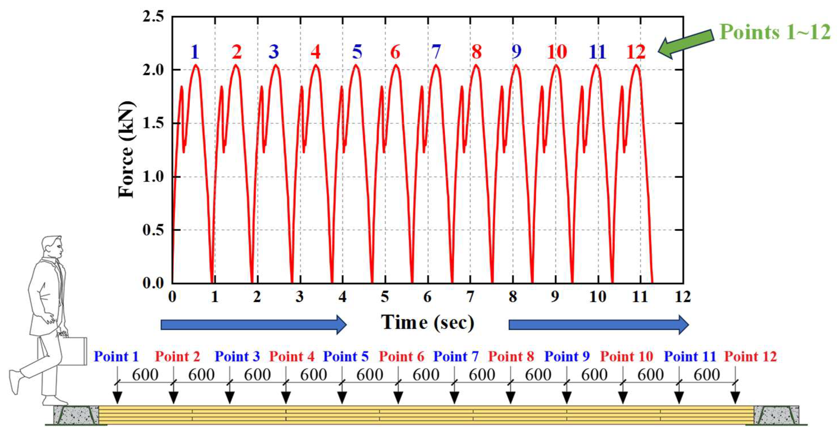
2.5. Dynamic Loading Methods
3. Parametric Study of Deltabeam–CLT Composite Floor System
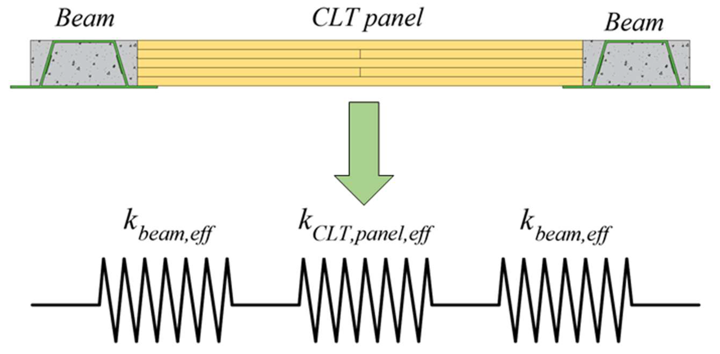
3.1. Theoretical Analysis
3.2. Simulation Scheme
3.3. Results Analysis
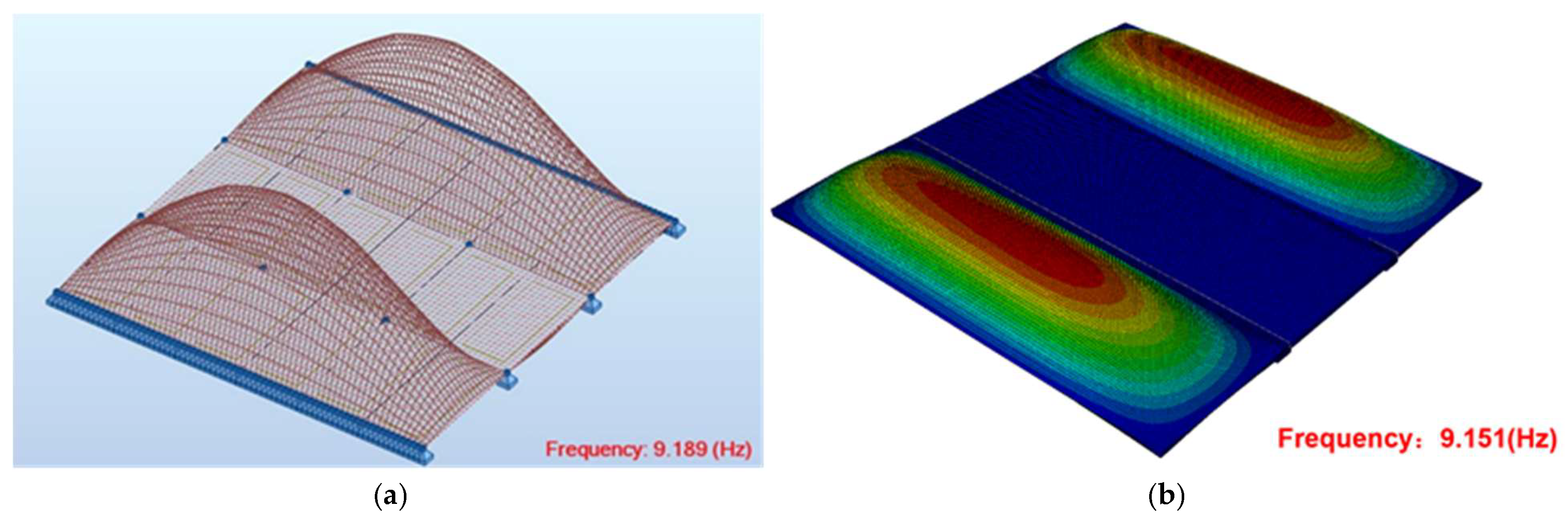
3.3.1. Natural Frequency Analysis
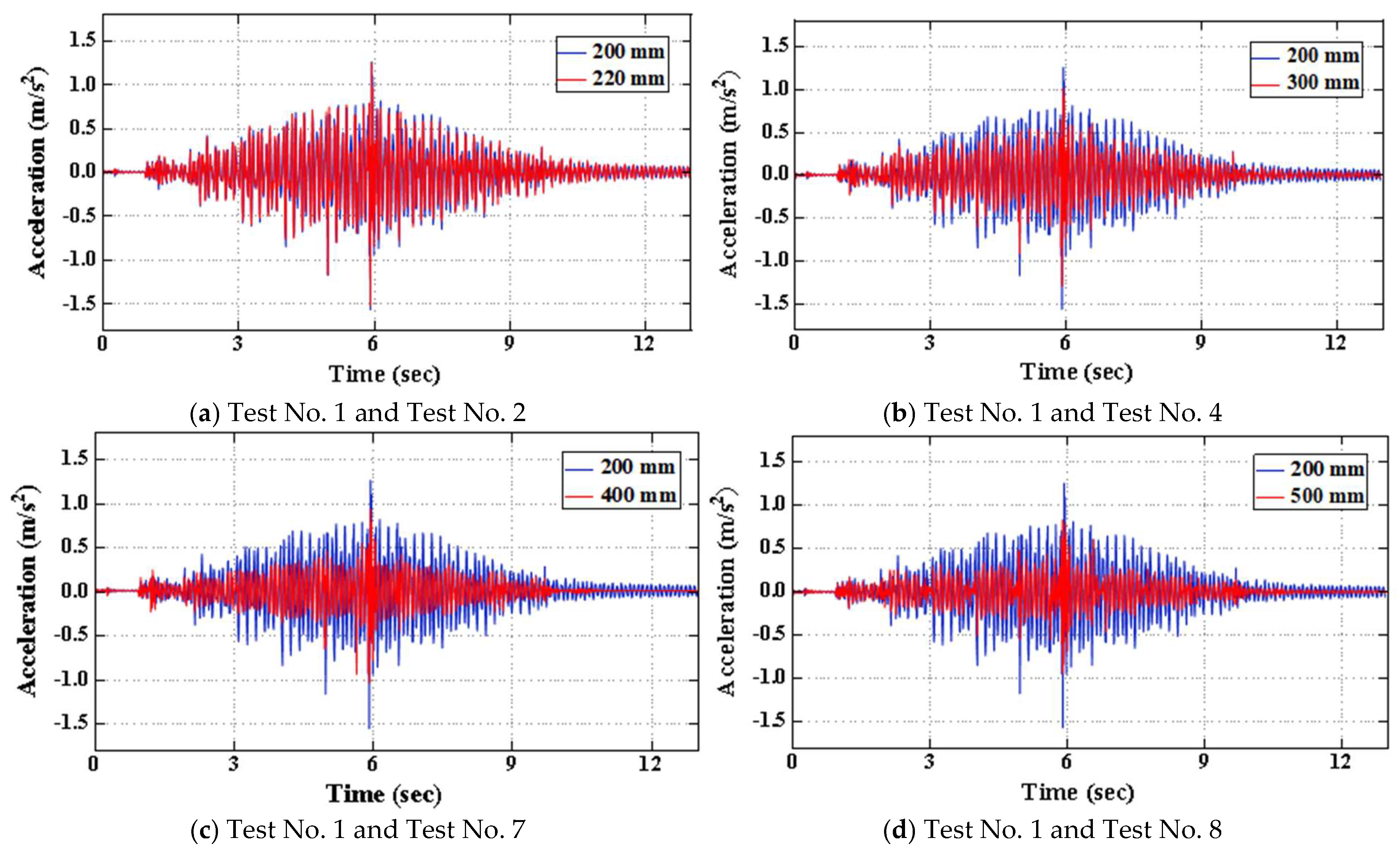
3.3.2. Time History Analysis
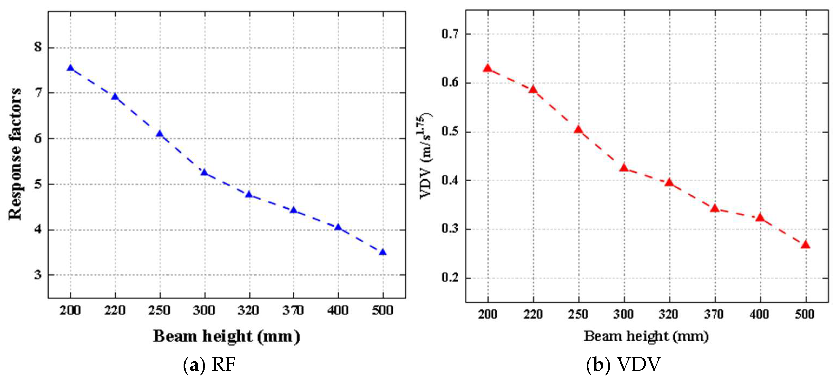
3.3.3. RF and VDV Analysis
3.4. Discussion
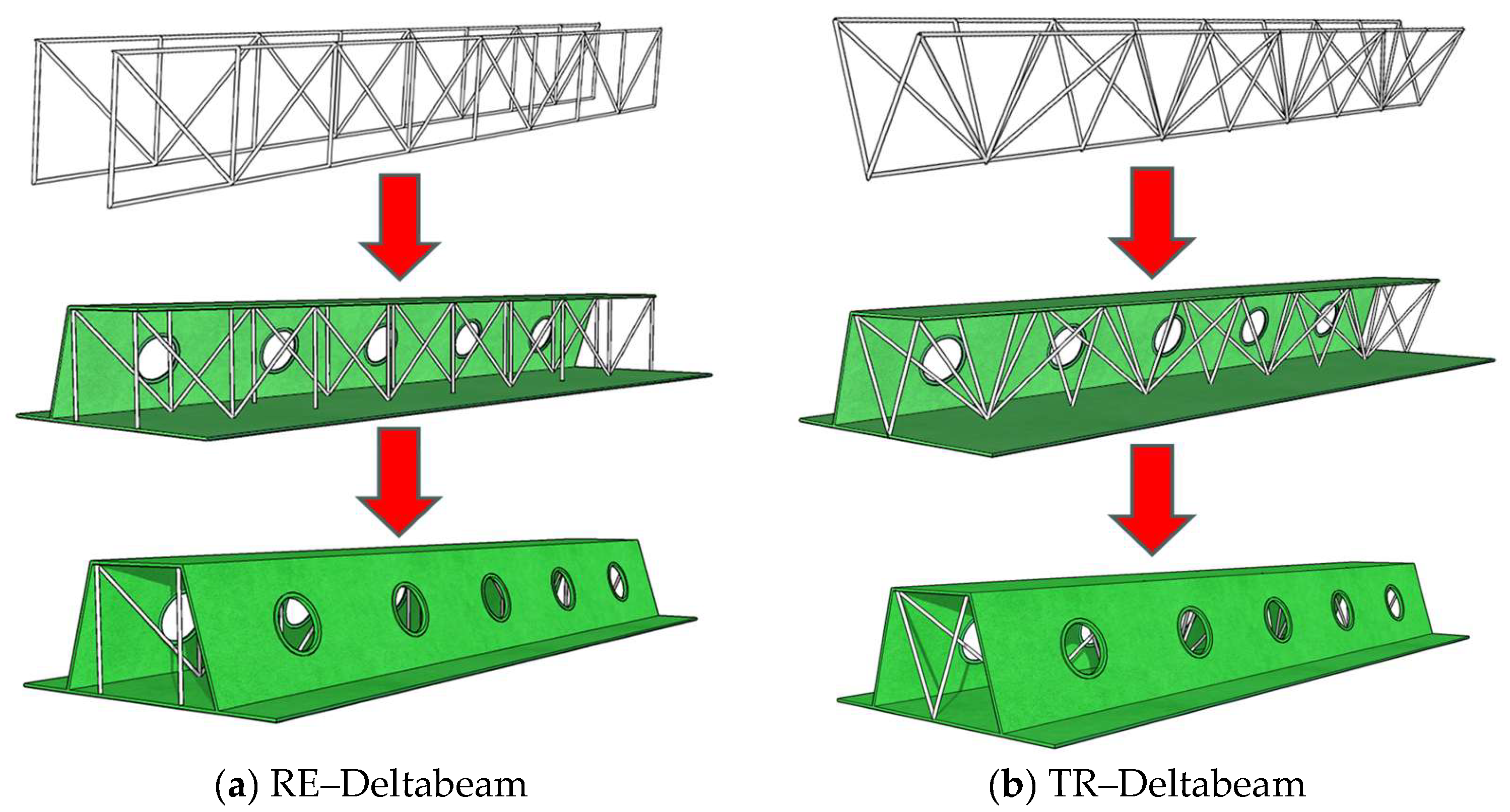
4. An Optimization Approach for Vibration Serviceability of Deltabeam–CLT Composite Floors Based on Embedded Steel Trusses
4.1. Optimization Scheme
4.2. Numerical Simulation of Deltabeam–CLT Composite Floors with Embedded Trusses
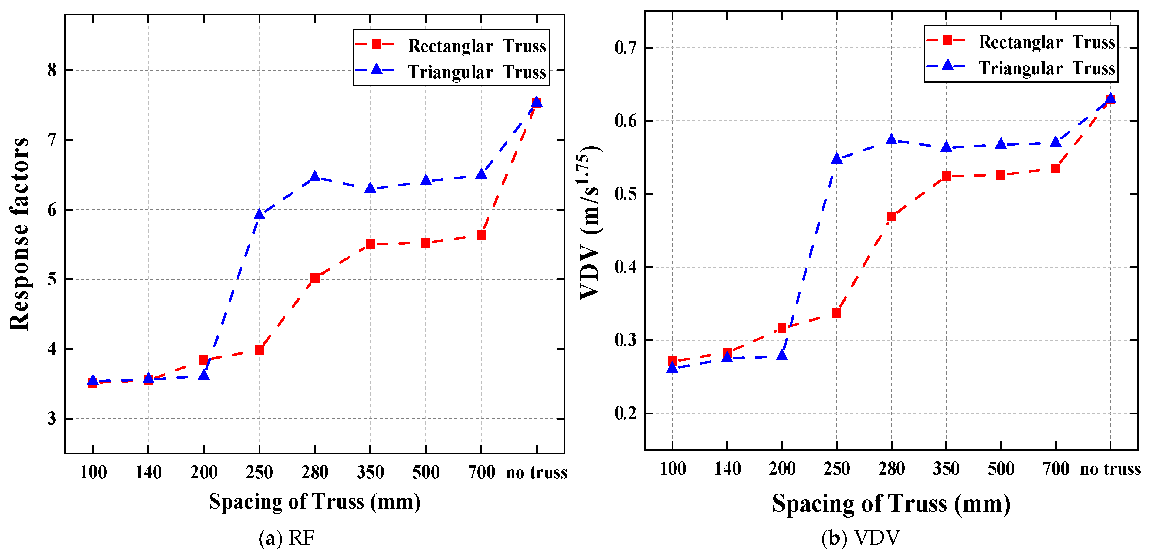
4.3. Impact of Truss Spacing on the Vibration Serviceability of Composite Floors
4.3.1. Test Schemes
4.3.2. Analysis of Results
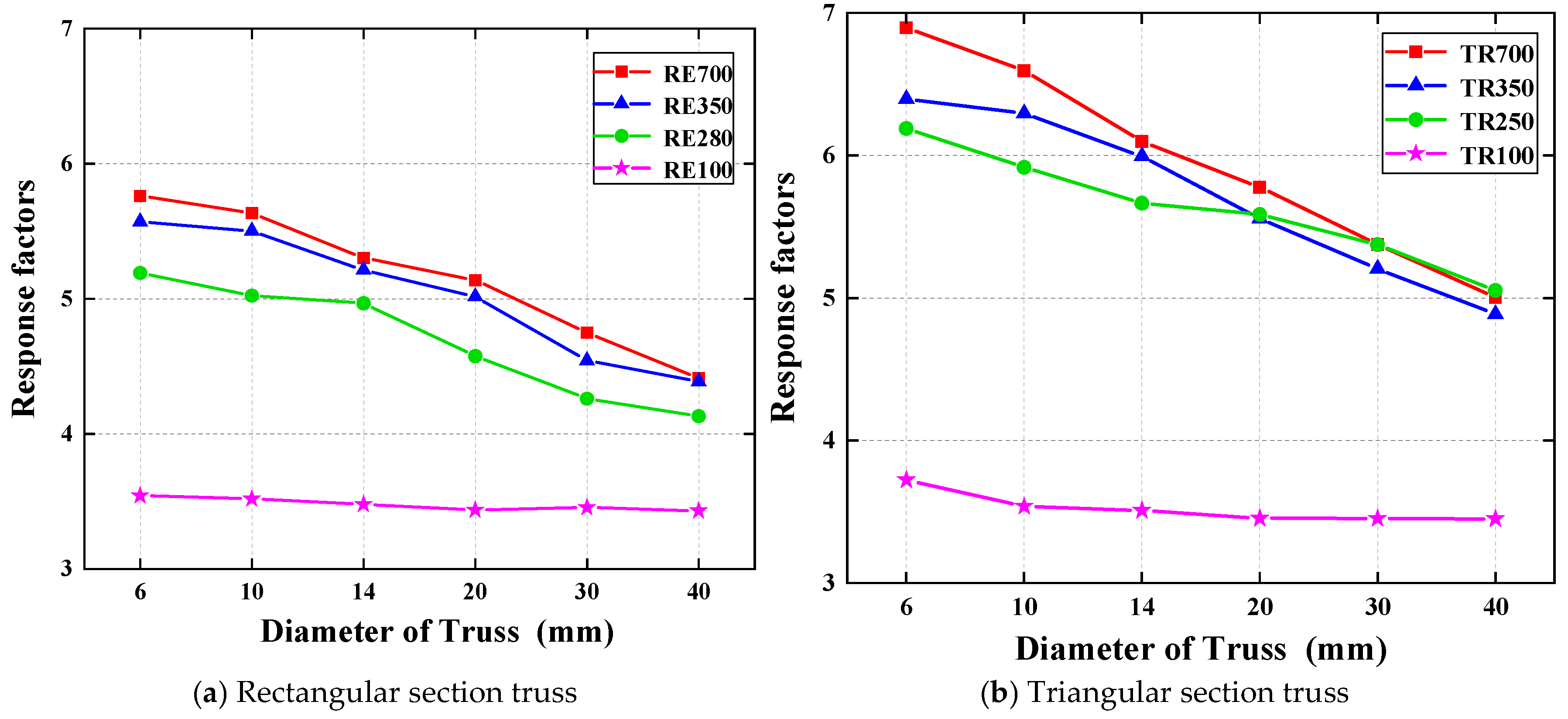
4.4. Impact of Truss Diameter on the Vibration Serviceability of Composite Floors
4.4.1. Test Schemes
4.4.2. Results Analysis
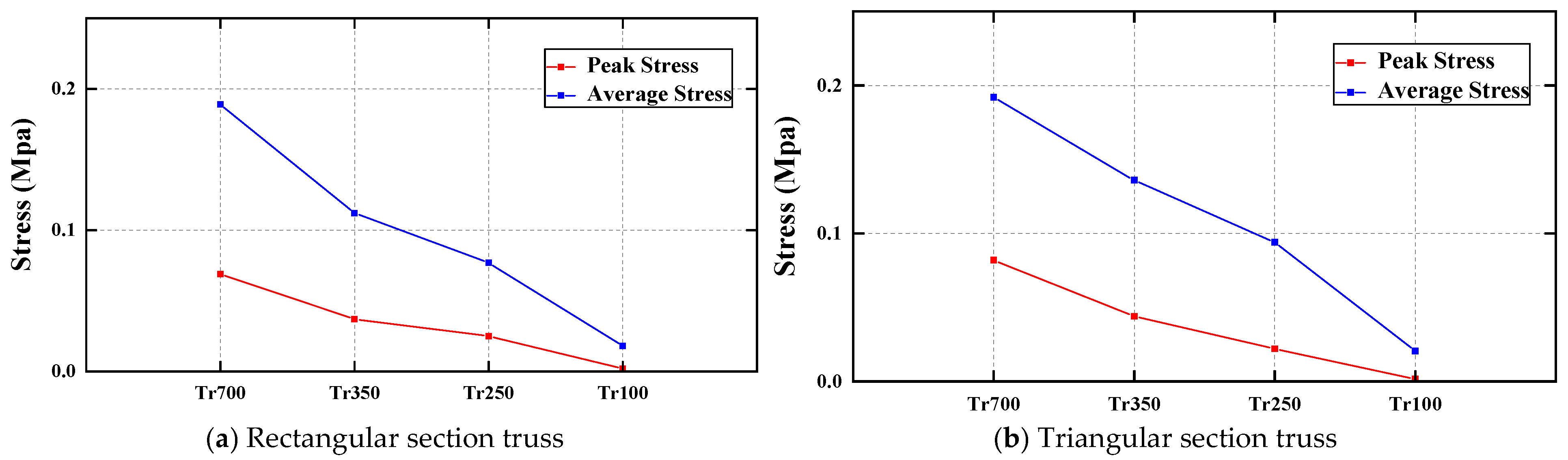
4.5. Discussion
5. Conclusions
- (1)
- According to the VDV and RF analysis of the CLT floor in this study, when the height of the Deltabeam composite steel beam is 200 mm, the RF of the Deltabeam–CLT composite floor is 7.533, and the VDV is 0.629 m/s−1.75.
- (2)
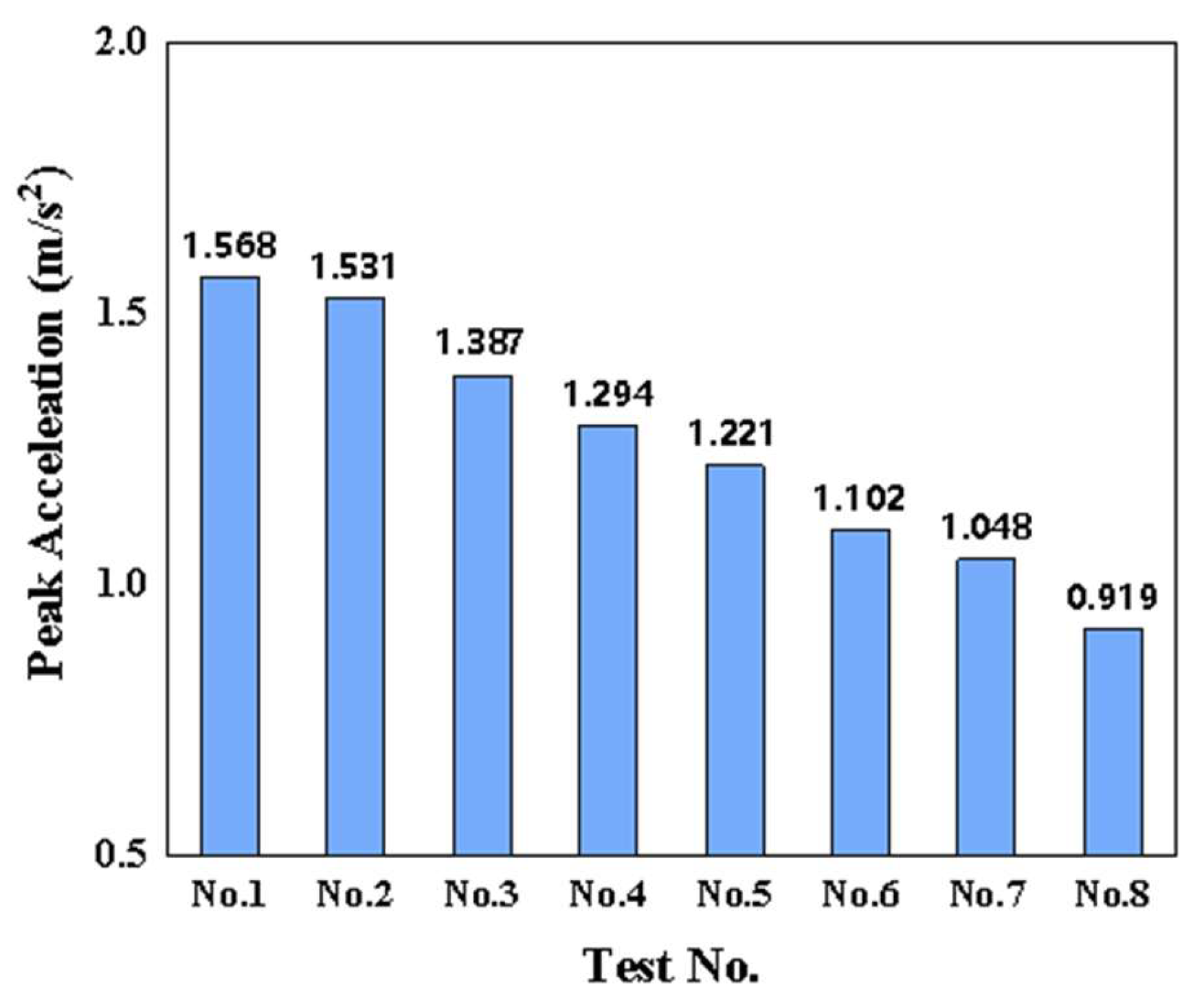
- Increasing the height of the Deltabeam effectively enhances the stiffness of the Deltabeam–CLT composite floor, thereby reducing its vibration response under human-induced vibration. When the height of the composite steel Deltabeam is increased from 200 mm to 500 mm, the first natural frequency of the Deltabeam–CLT composite floor increases by 23.07%. At the same time, its VDV and RF decrease by 57.7% and 53.7%, respectively, meeting the maximum limit requirements outlined in BS 6472 and ISO 10137.
- (3)
- An optimization scheme for vibration serviceability was proposed by embedding a steel truss within the Deltabeam. Two types of truss cross-sections, rectangular and triangular, were designed. The results of the numerical simulation indicate that, compared to the standard Deltabeam composite beam with a height of 200 mm, the incorporation of a steel truss with a spacing of 100 mm and a rod diameter of 10 mm leads to a maximum reduction in the RF and VDV of the Deltabeam–CLT composite floor by 45.54% and 54.21%, respectively, achieving the same vibration reduction effect as increasing the beam height to 500 mm.
- (4)
- Reducing the spacing of the trusses can effectively enhance the serviceability of the Deltabeam–CLT composite floor. By decreasing the truss spacing from 700 mm to 100 mm, the RF and VDV of the Deltabeam–CLT composite floor with rectangular section trusses decreased by 37.56% and 49.34%, respectively, while for the floor with triangular section trusses, the RF and VDV decreased by 45.54% and 54.21%, respectively.
- (5)
- Changing the diameter of the truss members shows a better vibration reduction effect when the truss spacing is under 100 mm. Although the natural frequency of the Deltabeam–CLT composite floor did not change significantly as the truss member diameter increased from 6 mm to 40 mm, its dynamic performance improved considerably, with RF and VDV decreasing by up to 27.44% and 32.39%, respectively.
- (6)
- According to the RF and VDV analyses, increasing the rod diameter of the steel trusses along with increasing the height of the Deltabeam can increase the stiffness of the Deltabeam and thus improve the overall vibration serviceability of the combined Deltabeam–CLT composite floor.
Author Contributions
Funding
Data Availability Statement
Acknowledgments
Conflicts of Interest
References
- Mayencourt, P.; Mueller, C. Structural optimization of cross-laminated timber panels in one-way bending. Structures 2019, 18, 48–59. [Google Scholar]
- Brandner, R.; Flatscher, G.; Ringhofer, A.; Schickhofer, G.; Thiel, A. Cross laminated timber (CLT): Overview and development. Eur. J. Wood Wood Prod. 2016, 74, 331–351. [Google Scholar] [CrossRef]
- D’Amore, G.K.O.; Caniato, M.; Travan, A.; Turco, G.; Marsich, L.; Ferluga, A.; Schmid, C. Innovative thermal and acoustic insulation foam from recycled waste glass powder. J. Clean. Prod. 2017, 165, 1306–1315. [Google Scholar] [CrossRef]
- Loss, C.; Davison, B. Innovative composite steel-timber floors with prefabricated modular components. Eng. Struct. 2017, 132, 695–713. [Google Scholar] [CrossRef]
- Hassanieh, A.; Valipour, H.; Bradford, M. Experimental and analytical behaviour of steel-timber composite connections. Constr. Build. Mater. 2016, 118, 63–75. [Google Scholar] [CrossRef]
- Hassanieh, A.; Valipour, H.; Bradford, M. Experimental and numerical study of steel-timber composite (STC) beams. J. Constr. Steel Res. 2016, 122, 367–378. [Google Scholar] [CrossRef]
- Hassanieh, A.; Valipour, H.; Bradford, M. Load-slip behaviour of steel-cross laminated timber (CLT) composite connections. J. Constr. Steel Res. 2016, 122, 110–121. [Google Scholar] [CrossRef]
- Ghanbari Ghazijahani, T.; Jiao, H.; Holloway, D. Composite timber beams strengthened by steel and CFRP. J. Compos. Constr. 2017, 21, 04016059. [Google Scholar] [CrossRef]
- Kyriakopoulos, P.; Peltonen, S.; Vayas, I.; Spyrakos, C.; Leskela, M.V. Experimental and numerical investigation of the flexural behavior of shallow floor composite beams. Eng. Struct. 2021, 231, 111734. [Google Scholar] [CrossRef]
- DELTABEAM. Composite Beams-Slim Floor Structure with Integrated Fireproofing; Peikko Group Technical Manual; Peikko Group: Lahti, Finland, 2021. [Google Scholar]
- Nádaský, P. Steel-concrete composite beams for slim floors–specific design features in scope of steel frames design. Procedia Eng. 2012, 40, 274–279. [Google Scholar] [CrossRef]
- DELTABEAM. Slim Floor Structure with Timber Construction; Peikko Group Technical Manual; Peikko Group: Lahti, Finland, 2022. [Google Scholar]
- West, S.M.; Camnasio, E.; Peltonen, S. Deltabeam with Timber Floor Joints—Load Bearing Capacity at Ambient Temperature and in Fire Situation. In Proceedings of the World Conference on TimberEngineering, Oslo, Norway, 19–22 June 2023; pp. 3167–3176. [Google Scholar]
- DELTABEAM. With Hybrid Timber Floors Load Transfer Tests; Peikko Group Technical Manual; Peikko Group: Lahti, Finland, 2022. [Google Scholar]
- DELTABEAM. High Fire Performance of Deltabeam Slim Floor Joints with Timber Slabs; Peikko Group Technical Manual; Peikko Group: Lahti, Finland, 2023. [Google Scholar]
- Chen, S.; Zhang, R.; Zhang, J. Human-induced vibration of steel–concrete composite floors. Proc. Inst. Civ. Eng.-Struct. Build. 2018, 171, 50–63. [Google Scholar] [CrossRef]
- Zhang, J.; Zhang, C.; Li, Y.; Chang, W.-S.; Huang, H. Cross-laminated timber (CLT) floor serviceability under multi-person loading: Impact of beam–panel connections. Eng. Struct. 2023, 296, 116941. [Google Scholar] [CrossRef]
- Huang, H.; Gao, Y.; Chang, W.-S. Human-induced vibration of cross-laminated timber (CLT) floor under different boundary conditions. Eng. Struct. 2020, 204, 110016. [Google Scholar] [CrossRef]
- Glisovic, I.; Stevanovic, B. Vibrational behaviour of timber floors. In Proceedings of the World Conference on Timber Engineering, Trentino, Italy, 20–24 June 2010. [Google Scholar]
- Huang, H.; Lin, X.; Zhang, J.; Wu, Z.; Wang, C.; Wang, B.J. Performance of the hollow-core cross-laminated timber (HC-CLT) floor under human-induced vibration. Structures 2021, 32, 1481–1491. [Google Scholar]
- Hassanieh, A.; Chiniforush, A.; Valipour, H.; Bradford, M. Vibration behaviour of steel-timber composite floors, part (2): Evaluation of human-induced vibrations. J. Constr. Steel Res. 2019, 158, 156–170. [Google Scholar] [CrossRef]
- ISO 10137; Bases for Design of Structures—Serviceability of Buildings and Walkways Against Vibrations. International Organisation for Standardisation (ISO): Geneva, Italy, 2007.
- Peikko Group. Performance of DELTABEAM-CLT Floors in Human-Induced Vibration; Peikko Group Technical Manual; Peikko Group: Lahti, Finland, 2020. [Google Scholar]
- EN 1995-1-1; Part 1-1: General Common Rules and Rules for Buildings. European Committee for Standardization: Brussels, Belgium, 2004; pp. 53–54.
- Simulia. ABAQUS 2016 ABAQUS/CAE User’s Manual; Simulia: Providence, RI, USA, 2015. [Google Scholar]
- Simulia. ABAQUS 6.11 ABAQUS/CAE User’s Manual; Simulia: Providence, RI, USA, 2011. [Google Scholar]
- Zhukov, P. Connection Details Between Composite Beam and Cross-Laminated Timber Slab. Bachelor’s Thesis, Häme University of Applied Sciences, Hämeenlinna, Finland, 2020. [Google Scholar]
- Dal Lago, B.; Martinelli, L.; Foti, F. Slender precast voided slabs under walking-induced vibration. Struct. Concr. 2022, 23, 3416–3443. [Google Scholar] [CrossRef]
- Gaspar, C.; Da Silva, J.S.; Costa-Neves, L. Multimode vibration control of building steel–concrete composite floors submitted to human rhythmic activities. Comput. Struct. 2016, 165, 107–122. [Google Scholar] [CrossRef]
- Jiang, L.; Cheng, R.; Zhang, H.; Ma, K. Human-induced-vibration response analysis and comfort evaluation method of large-span steel vierendeel sandwich plate. Buildings 2022, 12, 1228. [Google Scholar] [CrossRef]
- Ussher, E.; Arjomandi, K.; Weckendorf, J.; Smith, I. Prediction of motion responses of cross-laminated-timber slabs. Structures 2017, 11, 49–61. [Google Scholar]
- Galbraith, F.; Barton, M. Ground loading from footsteps. J. Acoust. Soc. Am. 1970, 48, 1288–1292. [Google Scholar] [CrossRef]
- Thelandersson, S.; Larsen, H.J. (Eds.) Timber Engineering; Wiley: Chichester, UK, 2003; p. 446. [Google Scholar]
- Ohlsson, S.V. Floor Vibrations and Human Discomfort. Ph.D. Thesis, Chalmers University of Technology, Division of Steel and Timber Structures, Gothenburg, Sweden, 1982. [Google Scholar]
- BS 6472-1:2008; Guide to Evaluation of Human Exposure to Vibration in Buildings—Part 1: Vibration Sources Other Than Blasting. British Standards Institution (BSI): London, UK, 2008.
- Lewis, K.; Basaglia, B.; Shrestha, R.; Crews, K. Innovation in the Design of Cross Laminated Timber for Long Span Floors. In Proceedings of the International Conference on Performance-Based and Life-Cycle Structural Engineering, Brisbane, QLD, Australia, 9–11 December 2015. [Google Scholar] [CrossRef]
- Wang, C.; Chang, W.-S.; Yan, W.; Huang, H. Predicting the human-induced vibration of cross laminated timber floor under multi-person loadings. Structures 2021, 29, 65–78. [Google Scholar]
- Huang, H.; Wang, C.; Chang, W.S. Reducing human-induced vibration of cross-laminated timber floor—Application of multi-tuned mass damper system. Struct. Control Health Monit. 2021, 28, e2656. [Google Scholar] [CrossRef]
- Tesser, L.; Scotta, R. Flexural and shear capacity of composite steel truss and concrete beams with inferior precast concrete base. Eng. Struct. 2013, 49, 135–145. [Google Scholar] [CrossRef]
- Tullini, N.; Minghini, F. Nonlinear analysis of composite beams with concrete-encased steel truss. J. Constr. Steel Res. 2013, 91, 1–13. [Google Scholar] [CrossRef]
- Zhang, N.; Fu, C.C.; Chen, L.; He, L. Experimental studies of reinforced concrete beams using embedded steel trusses. ACI Struct. J. 2016, 113, 701. [Google Scholar] [CrossRef]
- Zhang, X.; Deng, Z.; Deng, X.; Ying, J.; Yang, T.; Xu, J.; Zhang, C. Experimental study on seismic behaviors of beam with concrete-encased steel truss. Adv. Struct. Eng. 2018, 21, 2018–2029. [Google Scholar] [CrossRef]
- Renton, J.D. Behavior of Howe, Pratt, and Warren trusses. J. Struct. Div. 1969, 95, 183–202. [Google Scholar] [CrossRef]


| Density(kg/m3) | Elastic Modulus (MPa) | Poisson’s Ratio | Shear Modulus (MPa) | ||||||
|---|---|---|---|---|---|---|---|---|---|
| E11 | E22 | E33 | ν12 | ν13 | ν23 | G12 | G13 | G23 | |
| 500 | 11,600 | 730 | 530 | 0.59 | 0.57 | 0.24 | 610 | 860 | 120 |
| Eigenfrequency (Hz) | Modal Mass (kg) | Damping Ratios | |
|---|---|---|---|
| First-order mode | 8.28 | 3850 | 2% |
| Second-order mode | 10.44 | 2675 | 2% |
| Third-order mode | 17.25 | 1245 | 2% |
| Test No. | DELTABEAM® Profiles | Thickness of CLT (mm) | Height of DELTABEAM® (mm) |
|---|---|---|---|
| No. 1 | D20-400 | 200 | 200 |
| No. 2 | D22-400 | 220 | |
| No. 3 | D25-400 | 250 | |
| No. 4 | D30-400 | 300 | |
| No. 5 | D32-400 | 320 | |
| No. 6 | D37-400 | 370 | |
| No. 7 | D40-400 | 400 | |
| No. 8 | D50-600 | 500 |
| Beam height (mm) | 200 | 220 | 250 | 300 | 320 | 370 | 400 | 500 |
| First natural frequency (Hz) | 8.28 | 8.41 | 8.96 | 9.35 | 9.44 | 9.68 | 9.76 | 10.19 |
| Place | Time | Multiplying Factor for Exposure to Continuous Vibration 16 h Day 8 h Night | Impulsive Vibration Excitation with up to 3 Occurrences |
|---|---|---|---|
| Critical working areas (e.g., hospital operating theatres) | Day | 1 | 1 |
| Night | 1 | 1 | |
| Residential | Day | 2 to 4 | 60 to 90 |
| Night | 1.4 | 20 | |
| Office | Day | 4 | 128 |
| Night | 4 | 128 | |
| Workshops | Day | 8 | 128 |
| Night | 8 | 128 |
| Location Time | Unlikely to Have Negative Reviews (m/s−1.75) | There May Be Negative Reviews (m/s−1.75) | Likely to Have Negative Reviews (m/s−1.75) |
|---|---|---|---|
| 16 h of daylight | 0.2–0.4 | 0.4–0.8 | 0.8–1.6 |
| 8 h at night | 0.1–0.2 | 0.2–0.4 | 0.4–0.8 |
| Test No. | DELTABEAM® Profiles | B (mm) | Ø (mm) | Truss Section | Truss Spacing (b) |
|---|---|---|---|---|---|
| RE100 | D20-400 | 100 | 10 |  RE-Deltabeam | 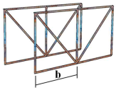 |
| RE140 | 140 | ||||
| RE200 | 200 | ||||
| RE250 | 250 | ||||
| RE280 | 280 | ||||
| RE350 | 350 | ||||
| RE500 | 500 | ||||
| RE700 | 700 | ||||
| TR100 | 100 |  TR-Deltabeam | 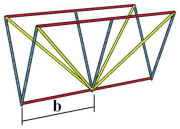 | ||
| TR140 | 140 | ||||
| TR200 | 200 | ||||
| TR250 | 250 | ||||
| TR280 | 280 | ||||
| TR350 | 350 | ||||
| TR500 | 500 | ||||
| TR700 | 700 |
| Spacing of Truss | 100 | 140 | 200 | 250 | 280 | 350 | 500 | 700 | No Truss |
|---|---|---|---|---|---|---|---|---|---|
| Rectangular truss (Hz) | 8.85 | 8.66 | 8.63 | 8.57 | 8.49 | 8.44 | 8.43 | 8.41 | 8.28 |
| Triangular truss (Hz) | 8.67 | 8.63 | 8.62 | 8.35 | 8.31 | 8.32 | 8.31 | 8.31 |
| Diameter(mm) | 6 | 10 | 14 | 20 | 30 | 40 | |
|---|---|---|---|---|---|---|---|
| Truss spacing | 100 mm | 8.66 | 8.85 | 8.89 | 8.76 | 8.71 | 8.83 |
| 280 mm | 8.49 | 8.49 | 8.51 | 8.50 | 8.47 | 8.40 | |
| 350 mm | 8.42 | 8.44 | 8.49 | 8.52 | 8.53 | 8.53 | |
| 700 mm | 8.40 | 8.41 | 8.45 | 8.46 | 8.45 | 8.45 | |
| Diameter(mm) | 6 | 10 | 14 | 20 | 30 | 40 | |
|---|---|---|---|---|---|---|---|
| Truss spacing | 100 mm | 8.65 | 8.67 | 8.74 | 8.75 | 8.83 | 8.71 |
| 250 mm | 8.30 | 8.35 | 8.39 | 8.39 | 8.41 | 8.41 | |
| 350 mm | 8.32 | 8.32 | 8.32 | 8.34 | 8.33 | 8.33 | |
| 700 mm | 8.30 | 8.31 | 8.35 | 8.31 | 8.32 | 8.31 | |
Disclaimer/Publisher’s Note: The statements, opinions and data contained in all publications are solely those of the individual author(s) and contributor(s) and not of MDPI and/or the editor(s). MDPI and/or the editor(s) disclaim responsibility for any injury to people or property resulting from any ideas, methods, instructions or products referred to in the content. |
© 2025 by the authors. Licensee MDPI, Basel, Switzerland. This article is an open access article distributed under the terms and conditions of the Creative Commons Attribution (CC BY) license (https://creativecommons.org/licenses/by/4.0/).
Share and Cite
Yang, H.; Wu, Y.; Shi, B.; Tao, H.; Huang, H. Performance of Deltabeam–CLT Composite Floors Under Human-Induced Vibration. Buildings 2025, 15, 2074. https://doi.org/10.3390/buildings15122074
Yang H, Wu Y, Shi B, Tao H, Huang H. Performance of Deltabeam–CLT Composite Floors Under Human-Induced Vibration. Buildings. 2025; 15(12):2074. https://doi.org/10.3390/buildings15122074
Chicago/Turabian StyleYang, Huifeng, Yushuang Wu, Benkai Shi, Haotian Tao, and Haoyu Huang. 2025. "Performance of Deltabeam–CLT Composite Floors Under Human-Induced Vibration" Buildings 15, no. 12: 2074. https://doi.org/10.3390/buildings15122074
APA StyleYang, H., Wu, Y., Shi, B., Tao, H., & Huang, H. (2025). Performance of Deltabeam–CLT Composite Floors Under Human-Induced Vibration. Buildings, 15(12), 2074. https://doi.org/10.3390/buildings15122074