Article

Blast Performance of Multi-Layer Composite Door Panel with Energy Absorption Connectors

1
Key Lab of Structures Dynamic Behavior and Control of the Ministry of Education, Harbin Institute of Technology, Harbin 150090, China
2
Key Lab of Smart Prevention and Mitigation of Civil Engineering Disasters of the Ministry of Industry and Information Technology, Harbin Institute of Technology, Harbin 150090, China
*
Author to whom correspondence should be addressed.
Buildings 2025, 15(12), 2073; https://doi.org/10.3390/buildings15122073
Submission received: 7 May 2025 / Revised: 2 June 2025 / Accepted: 13 June 2025 / Published: 16 June 2025
(This article belongs to the Section Building Structures)

Abstract

:
Doors are considered vulnerable to failure in structures when subjected to extreme loads, such as blasts. Consequently, blast-resistant doors are designed to withstand blast pressure in important structures. This study developed a multi-layer Steel, Aluminum Foam, and Steel–Concrete–Steel composite door panel with Energy Absorption Connectors (SAFSCS-EACs) under near and far field blast loading using finite element analysis in LS-DYNA. Three dynamic response modes were observed based on the crushing strength of energy absorption connectors (EACs) for the SAFSCS-EAC composite door under both near and far field blasts. In addition, the membrane stretching phenomena was observed in the face steel plate. The AF shows a local densification in near field blasts and a global densification in far field blasts. For the SCS panel, a punching-like failure and a global flexural failure were observed in near and far field blasts, respectively. AF has a high energy absorption capacity as a first energy absorption layer, while the EAC also effectively dissipates blast energy through the rotation of the plastic hinges of curved steel plates, thereby reducing the damage to the SCS panel and increasing the door’s structural integrity. Moreover, to check the influence of the curved steel plate thickness of EACs and the core concrete thickness, a parametric study was carried out. The results showed that the blast resistance performance of the SAFSCS-EAC composite door could increase by appropriately designing the EAC curved steel plates’ thickness and ensuring that the compression displacement of the EAC under blast is close to its densification displacement. Additionally, increasing concrete thickness can reduce the degree of damage to the steel–concrete–steel composite panel during the blast, but it leads to a reduction in the energy dissipation of the EAC.

1. Introduction

Determining the weakest points in any protective structure and minimizing potential damage at those points is crucial in design [1]. In most blast-resistant structures, the door is considered the weakest point due to its necessity for human access. Even if other structural components, such as walls, are designed to be blast-resistant, an inadequately reinforced door can allow shock fronts from explosions to penetrate and cause significant damage [2]. Thus, blast-resistant doors act as critical barriers against energy transfer from pressure waves and solid fragments resulting from explosions. These doors prevent damage to both the structure and its occupants and are primarily used in ammunition storage compartments, defense shelters, tunnels, and subways.
Recent research has extensively explored the blast resistance of monolithic steel plates [3,4,5] and steel–concrete–steel door panels, both flat and curved [6,7,8], as well as reinforced steel panel structures [9,10] subjected to blast loads. Additionally, significant studies have been conducted on the blast resistance of panels made from innovative materials and designs [11,12,13], such as foam and honeycomb core sandwich panels, which have shown exceptional energy absorption capabilities [14,15,16,17]. However, these designs typically involve internal energy dissipation only, relying solely on the sandwich panel’s deformation behavior and core densification for blast force mitigation.
Steel–concrete–steel (SCS) composite panels have become significant in the design of blast resistance structures because of their distinctive structural properties that combine the high strength of steel plates with the inertia of core concrete [18,19,20,21]. The SCS sandwich panel provides an effective solution for mitigating blast forces and also performs well under impact load [22]. Zhao et al. [23] investigate the blast response of the SCS panels and reinforced concrete (RC) panels. The results showed that SCS panels have superior performance over RC panels with reduced mid deflection and no concrete splash damage. Yu et al. [24] also investigated SCS and RC panel blast resistance performance and showed that SCS panels have superior blast resistance and greater flexural capacity over RC panels. The SCS panel has been extensively utilized for nuclear reactors in the literature [25,26,27], and it has been demonstrated that the SCS panels are more vigorous and durable compared to RC panels. Koh et al. [28] developed parametric studies of steel and steel–concrete composite blast-resistant doors; the results showed that the SCS panel shows high performance under blast because of its high steel strength and the increased inertia of the core concrete. Despite their effectiveness, most SCS studies overlook connection systems and interface behavior critical to real-world applications like blast doors. Moreover, the integration of external energy-absorbing elements, such as metal foams or connectors, remains underexplored, limiting blast force mitigation to surrounding structures.
Over the past decades, several researchers have implemented systematic research on the energy absorption performance of various energy-absorbing components [29,30,31]. Among them, porous foam materials, such as metal foams, polymer foams, and biomaterials, are commonly used as energy-absorbing components [32]. Yun et al. [33] evaluated blast doors incorporating aluminum alloy foam, demonstrating significant weight reductions while maintaining structural integrity under blast loads. Ganorkar et al. [34] investigated the comparative performance of a three-hinged, five-latched, double-leaf composite door subjected to blast loading using finite element analysis software, Ls-Dyna. The numerical results showed that the polyurethane core door performed best with a 150 mm core, while the plain concrete and cenosphere aluminum alloy core doors demonstrated enhanced performance with 100 mm core thicknesses at various scaled distances. However, these studies primarily focused on core material variation within panel interiors and did not explore multi-layer configurations or interface-level energy dissipation mechanisms.
In addition to the foam materials, thin-walled metal components are commonly used energy-absorbing elements. Wang et al. [35] introduce a novel energy absorption connector designed to be integrated between a blast-resistant facade and a building. The results showed that energy absorption connectors effectively dissipate the blast energy during the blast event. Wang et al. [36] examined the effectiveness of energy absorption connectors under both quasi-static and dynamic crushing states. The findings illustrated that energy absorption connectors performed better under dynamic loading compared to quasi-static loading. Harris and McShane [37] introduced a metal-stacked origami structure for energy absorption, highlighting that folding shape and angle affect energy efficiency. Baroutaji et al. [38] found that increasing strain rates strengthens thin-walled metal energy-absorbing components, enhancing their energy absorption capacity. However, these studies mainly investigate component-level behavior and do not address their integration with blast-resistant panel systems or structural interfaces, limiting their practical implementation in full-scale protective designs.
In light of the existing research, there is a lack of an integrated approach that combines the rigid strength of SCS, the lightweight energy absorption of metal foam, and the EAC to decrease the transmitted blast force to the rigid support. Their combined use in a hierarchical, system-level blast mitigation strategy has not been adequately explored. Hence, this study proposes a new rigid–flexible multi-layer protective door consisting of a Steel Aluminum Foam Steel–Concrete–Steel (SAFSCS) panel with Energy Absorption Connectors (EACs). The EAC can be inserted between the door frame and the rigid support to increase the blast resistance of the door and decrease the transmitted blast force to the rigid support [39]. The SAFSCS-EAC system offers key engineering advantages, including weight reduction through aluminum foam for easier transport and installation, cost-efficiency using readily available materials, ease of fabrication with conventional methods, and versatile applications. This study develops a finite element model in LS-DYNA to simulate the SAFSCS-EAC panel under near and far field blast loads, investigating its response modes with varying EAC thicknesses and blast TNT charges. A detailed parametric analysis was conducted on the thickness of the core concrete and curved EAC plates to identify an optimal design balancing structural performance and practical applicability.

2. Methodology

This study utilizes LS-DYNA R11-1-0 [40] to develop a finite element (FE) model for simulating the blast resistance performance of the SAFSCS-EAC door, and the blast load was applied to the door panel via the CONWEP program.

2.1. Design of the Blast-Resistant Door

The blast-resistant door frame should be designed to hold the door together [1], as failure to do so can result in the door becoming a life-threatening projectile. Additionally, the panel must be easy to operate and effectively resist blast energy. To address these requirements, a Steel–Aluminum Foam–Steel–Concrete–Steel (SAFSCS) door panel with energy absorption connectors (EACs) has been designed in the present work after several numerical iterations. The proposed model involves layering different materials in a specific order to optimize the door’s blast resistance.
Figure 1 exhibits the detailed drawing of the SAFSCS-EAC panel consisting of a face steel plate, a flexible aluminum foam (AF), and a steel–concrete–steel (SCS) sandwich panel resting on a steel tubular frame with concrete inside. The EAC was inserted between the door frame and the rigid support. Figure 1b shows the geometric dimensions of the SAFSCS, the length and width of the face steel plate, and the AF; the SCS composite panel is 1836 × 980 mm. The faceplate has a thickness of only 2 mm, serving primarily as a protective skin to shield the underlying aluminum foam from direct impact during a blast. The aluminum foam, which functions as the primary energy absorber, has a thickness of 50 mm. The thickness of the top steel, the bottom steel plate, and the concrete core of the SCS panel is 2.85, 2.85, and 70 mm, respectively. The concrete layer adds mass and stiffness to withstand the high strain rates typical of blast impacts. The spacing and diameter of the bolt in the SCS panel were 51 mm and 6.35 mm, respectively. The support frame used for the SAFSCS composite door panel is rectangular steel–concrete. The external dimensions of the frame are 1986 mm in length and 1080 mm in width, with a uniform frame width of 200 mm on all four sides. The frame is hollow in the middle, forming an open rectangular area. It is composed of an 8 mm thick steel enclosure on all sides, which fully surrounds and contains the internal concrete core. The total height of the frame is 40 mm. The concrete inside of the tubular frame enhances its structural rigidity, thereby distributing the blast impact more effectively, which significantly reduces the frame’s failure due to buckling.
Figure 1c demonstrates the dimensions of the EAC. Each EAC consists of 6 curved steel plates on the long side of the door and 2 curved steel plates on the short sides. The width, height, and inner radius of the curved steel plates are 150, 150, and 75 mm, respectively. Additionally, curved steel plates have top and bottom steel plates of 8 mm thickness, which were inserted between the door frame and the rigid support. The EAC curved steel plate thicknesses of 40, 12, and 6 mm were chosen to represent distinct structural responses, as 40 mm corresponds to a highly stiff configuration with minimal deformation, 12 mm reflects a moderately flexible state that enables compression without full compaction, and 6 mm captures the behavior under full compaction, indicating a more deformable, low-stiffness condition. Detailed information on the different parameters of the modeled doors is given in Table 1. For simplicity and clarity, the specimens are labeled in this study, e.g., SAFSCS-EAC40T20, the SAFSCS, is Steel Aluminum Foam, Steel–Concrete–Steel, and EAC represents energy absorption connectors, while 40 shows the curved steel plates’ thickness of the EAC in mm, while T20 T represents the TNT and the numerical values shows the mass in kg. All of the specimens shared the same dimensions apart from the curved steel plates’ thickness.

2.2. FE Model Description

Figure 2 shows the FE model of the SAFSCS-EAC blast resistance door, while detailed information of all of the simulated specimens is given in Table 1. The steel plates and rigid supports were modeled using shell elements, with five Gauss integration points through the thickness assigned to these elements. Solid elements were used to represent the concrete core and the aluminum foam, while the bolt connectors in the SCS were modeled using beam elements. Concerning the contact treatment, the “CONTACT_AUTOMATIC_SURFACE_TO_SURFACE” algorithm is used for the interactions between the aluminum foam and the top steel plate, as well as between the steel plates and the concrete. The static and dynamic coefficients were set at 0.2. This algorithm, well-suited for handling contacts between dissimilar materials, applies a soft constraint-based approach to accurately simulate the dynamic interactions and ensure realistic behavior under blast impacts.
Additionally, the “CONTACT_TIED_NODES_TO_SURFACE” keyword is utilized to model the connections between bolts and the top and bottom steel plates of the SCS panel. This contact method ensures that the slave nodes move in unison with the master surface, effectively simulating the mechanical connections and maintaining the integrity of the assembly. The same contact approach is used to tie the aluminum foam to the top plate and to connect the EAC top plate to the steel frame, as well as the curved plates to both the top and bottom EAC plates. Additionally, the bottom EAC plates were connected to the rigid support through the same contact algorithm. This cohesive contact strategy ensures a robust structural assembly capable of withstanding complex loading scenarios typical of blast impacts, providing an understanding of the performance and failure modes of the sandwich door. All translational degrees of freedom for the rigid support were constrained at the nodes of the rigid support to ensure stability. Additionally, the nodes at the symmetrical surface of the numerical model were restrained in the translational direction along the normal direction and in rotation around the tangential direction. The keyword “LOAD_BLAST_ENHANCED,” derived from the CONWEP program, was employed to replicate the blast load on SAFSCS-EAC blast-resistant doors. In the CONWEP program, blast pulses are automatically defined by specifying the mass of the TNT charge, blast type, and standoff distance. Additionally, a group of elements must be designated as the contact surface to accept the pressure from the blast load, which is done using the “BLAST_SEGMENT_SET” keyword. Blast loads were applied to all SAFSCS-EAC doors, as shown in Table 1. The TNT charge was centered on the panel, as illustrated in Figure 2.

2.3. Material Model

The Piecewise Linear Plasticity material model to simulate the mechanical properties of steel was used, corresponding to the material model MAT_24 of LS-DYNA. This material model was considered for its ability to incorporate arbitrary stress versus strain curves and strain rate dependencies, allowing for detailed and realistic characteristics of steel behavior under various loading conditions. The Cowper–Symonds model is used to consider the strain rate effect of low-carbon steel, that is, by introducing the strain rate strengthening factor DIF, the strain rate strengthening effect is simulated. The expression of DIF is [41]
D I F = σ d y ε , ε σ y ε = 1 + ε C 1 / P
where σ d y and σ y are the dynamic yield stress and the static yield stress, respectively, and ε and ε are the equivalent plastic strain and strain rate of the steel. C and p are the strain rate parameters. In this study, the parameters C and p were adopted as 802 s−1 and 3.585, respectively [41]. The bolts, which were mathematically embedded in the concrete elements, assumed a perfect bond using MAT_024 material models. The input true stress versus effective plastic strain curves for mild steels, curved steel, and EAC steel plates are provided in Figure 3a. The supports were modeled with solid elements using the ELASTIC material model (MAT_001).
The mechanical properties of the concrete material of the SAFSCS-EAC composite door panel are simulated using the Continuous Surface Cap Model (CSCM), which corresponds to the LS-DYNA material model *MAT_159 [42]. This model is widely used to simulate the dynamic mechanical behavior of concrete materials. The material model was introduced by the US Highway Administration to assess the damage and deformation of concrete in roadside safety structures exposed to blast and vehicle contact load [43]. This material model is a cap model, which defines three yield surfaces in the material yield stage: the plastic yield surface, the shear yield surface, and the cap hardening surface. In addition, the strain rate effect of concrete is considered by the following expression:
σ i j v P = 1 γ σ i j T + γ σ i j P γ = Δ t / η 1 + Δ t / η
where σ i j v P , σ i j T , and σ i j P are, respectively, the viscoplastic stress tensor, the elastic stress tensor, and the viscous stress tensor without considering strain rate effects. Δ t and η are the time step and equivalent flow coefficient, respectively.
In this study, the input parameters for the CSCM material model in LS-DYNA were selected based on the established literature. The compressive strength was set to 42.7 MPa, the elastic modulus was set to 24.3 GPa, and the Poisson’s ratio was set to 0.2. These parameters were used as inputs for the material model in LS-DYNA. Furthermore, the parameters for the CSCM material model were automatically generated using LS-DYNA based on these input values. The IRATE option was used to add the strain rate influence on concrete material into the FE model. The performance of the aluminum foam material in the SAFSCS-EAC composite door panel was simulated using the crushable foam model, which corresponds to the material model MAT_63 of LS-DYNA. The compressive stress–volume strain relationship curve of aluminum foam is shown in Figure 3b. Furthermore, this study assumes the aluminum foam to be homogeneous and isotropic for simplification and computational efficiency. The specific material parameters characterizing the behavior of the aluminum foam, steel plates, and concrete are detailed in Table 2.

2.4. Validation of FE Model

Because no experimental work was performed on SAFSCS-EAC doors subjected to blast load, a reference specimen was chosen from Bruhl and Varma’s [44] experimental work for the SCS panel. They [44] experimentally investigated steel plate composite (SC) walls under blast loading generated by a blast simulator. For the energy absorption connectors (EACs), the experimental work performed by Wang et al. [45] was compared with FE results for the reliability and accuracy of simulations.

2.4.1. Part 1

Bruhl and Varma [44] conducted experimental investigations of steel plate composite (SC) walls subjected to blast loading generated by a blast simulator. The detailed test setup is illustrated in Figure 4. In their experiments, a specimen labeled 3-2-50-5 was subjected to shot 1, while another specimen, labeled 5-2b-50-5, was subjected to shock waves 3 and 4. Additionally, a specimen labeled 5-2-50-5 was subjected to shock wave 6. These specimens were chosen as reference tests for validation purposes. In total, four specimens from Bruhl and Varma’s [44] study were selected as reference specimens for validation. As shown in Figure 4, the specimen measured 1626 mm in length, 279 mm in width, and 102 mm in thickness. The steel plate used in the specimen has a thickness of 2.85 mm. The shear connectors in this experiment comprise headed stud anchors and tie bars. The anchors, with a diameter of 6.35 mm and a length of 28.58 mm, were located at a spacing of 51 mm. The tie bars, which were threaded steel rods also with a diameter of 6.35 mm, were placed at 51 mm intervals between the two steel plates, as shown in Figure 4.
The FE model of SC is illustrated in Figure 5. The tie bars and studs were modeled using beam elements, which were embedded in the concrete elements, assuming a perfect bond, using MAT_024 and MAT_003 (Plastic Kinematic) material models. The input true stress versus effective plastic strain curves for mild steel are provided in Figure 3a. Moreover, steel material was subjected to a failure criterion of 0.18 strain. The supports and frame were modeled with solid elements using the ELASTIC material model (MAT_001). A uniformly distributed blast pressure depicted in [44] was applied to the surface by using the keyword “LOAD_SEGMENT_SET”. After mesh sensitivity analysis, the final mesh size used for the concrete was 12.75 mm by 12.75 mm by 10 mm, and that of the steel plate was 12.75 mm by 12.75 mm by 2.85 mm, which provided a balance between computational efficiency and accuracy in the results.
Figure 6 present a comparison of the effective plastic strain distribution, used as a damage index, within the concrete core after shot 4 and shot 6 analyses, respectively. The crack patterns observed in the FE simulations closely resemble those seen in the experimental tests [44], demonstrating strong agreement between numerical and experimental results [44]. Both numerical and experimental data [44] suggest that the wall exhibited deformation in a flexural mode. In the tests, multiple pronounced flexural cracks developed at the rear (non-blast) surface. Similarly, the numerical results highlight significant damage in this region. However, the numerical analysis, due to its stronger boundary conditions, showed additional damage in the concrete elements adjacent to the supports.
Additionally, the numerical peak displacements, as depicted in Table 3, of shots 1, 3, and 4 and shot 6 of the reference specimen closely match the experimental results. Overall, the numerical model effectively replicates the dynamic response and crack patterns of the CFDSPC wall specimen under blast loading conditions, providing a reasonable approximation of its behavior in the physical tests. The minor differences between experimental and numerical results may be ascribed to factors like material properties, boundary conditions, or modeling assumptions. Overall, the numerical simulation provides a reliable representation of the structural response, supporting its use in further analysis and design.

2.4.2. Part 2

In this validation part, the EAC was validated with experimental work by Wang et al. [45]. The energy absorption connectors without aluminum foam were chosen as the reference specimens. The FE model of the energy absorption connector under quasi-static compression loading is depicted in Figure 7a. As shown in Figure 7b, two 20 mm thick steel plates were bolted to the top and bottom of the connector to prevent bending deformation and replicate the actual boundary conditions, and no detachment was seen during the experiment. Consequently, the single steel plate with 28 mm thickness was selected as a substitute. The actuator was modeled to have a steady downward velocity to load the connector. To eliminate the inertia effect and establish a quasi-static loading rate, the kinetic energy was maintained at less than 5% of the internal energy.
Figure 8 shows the comparison of the collapse process of the connectors. The graph shown in Figure 9 is a compelling visualization of the validation process between experimental and FE results for the energy absorption connectors. The graph plots compressive force against displacement, illustrating how these connectors behave under quasi-static compression loading. The compressive force–displacement curves for the energy absorption connectors, derived from both experimental tests and FE analyses, are compared in Figure 9.
Additionally, Table 4 presents a comparison of the mean force values. The results indicate that the FE models closely predict the compressive force–displacement behavior of the connectors. Three distinct deformation stages are observed: elastic deformation, plastic deformation, and the inner surface contact stage [46]. In the elastic deformation stage, a linear relationship between force and displacement is clear. During plastic deformation, the force continues to increase, with its progression influenced by both the geometric changes of the curved plate and the material hardening of the steel. A sharp rise in compressive force occurs once the inner surface of the pleated or curved plate makes contact, marking the stage at which the connectors reach their ultimate energy absorption capacity. These findings confirm that the FE model is reliable and effectively captures the behavior of energy absorption connectors under quasi-static compression loading.

3. Results

Blast-resistant doors respond dynamically to be able to endure blast loads and dissipate energy. Aluminum foam is a crucial component for energy absorption in SAFSCS-EAC door panels between the door frame. Most of the blast energy is absorbed by the 50 mm thick aluminum foam layer, which is the same for all door configurations. The AF quickly rises to absorb most of the blast energy within the first two milliseconds for both near field and far field blasts, demonstrating the foam’s excellent energy dissipation efficiency. The SAFSCS-EAC door responds to the applied blast TNT in three distinct ways because of the three variable crushing strengths of the EAC. The deformation processes of the three response modes for the SAFSCS-EAC door under near field and far field blast loads are illustrated in Figure 10 and Figure 11, respectively.

3.1. Response Mode 1

SAFSCS-EAC-40 exhibits response mode 1, which shows insignificant compression displacement of EAC. This features EAC curved steel plates with a thickness of 40 mm. The crushing of the EAC has not been triggered in response mode 1 for the near and far field blast detonation, and the SAFSCS deforms extensively, allowing the SCS panel to attain maximum deflection. Figure 12 displays the force, displacement, and internal energy curves of SAFSCS-EAC40T20 for the AF, SCS, and EAC in the case of a near field blast. The force’s blast force was determined by multiplying the blast pressure (obtained from LS-DYNA using the keyword “*DATABASE_BINARY_BLSTFOR”) by the area of the face steel plate and the reaction force (the vertical contact force between the specimen and the rigid support). The deformation process of SAFSCS-EAC40T20 for response mode 1 is depicted in Figure 10a.
The time–history graphs show that the aluminum foam as a first energy absorption layer absorbs the bulk of the internal energy soon after the blast force impact while, at that instance, the EAC and SCS begin to deflect practically immediately after the blast energy transfer from Steel Aluminum Foam (SAF) to the SCS-EAC. The EAC reaches its maximum displacement and internal energy absorption when t = 1.6 ms, which is insignificant in the case of response mode 1. Thereafter, the SCS panel shows a peak in both deflection and internal energy as the SCS panel absorbs the majority of the blast impact. At t = 2.99 ms, the SCS reaches its maximum deflection and internal energy absorption, as shown in Figure 10a and Figure 12. There is an elastic recovery stage after this peak during which the deflection and internal energy of the SCS panel show reductions, as depicted in Figure 12.
An analysis of the SAFSCS-EAC40T20 reveals that the SAFSCS panel is triggered to accelerate downward under the blast’s force, which results in a sharp increase in the inertial force of the SAFSCS panel. Additionally, the reaction force of the EAC is insignificant because of the high-order vibration of the SAFSCS; as the inertial force keeps decreasing, the SAFSCS moves downwards, and the deflection and internal energy of the SCS panel keep increasing. The blast force and the reaction force of the EAC demonstrate a continuous decrease when the panel starts to rebound at t = 5.19 ms. Thereafter, the SCS panel starts to oscillate and then finally becomes stable.
On the other hand, in the case of a far field blast, the SAFSCS-EAC-40 door’s response exhibits a comparable pattern, though with some significant variations in the blast force and distance. The force, displacement, and internal energy time histories for the SAFSCS-EAC40T100 door are depicted in Figure 13, and the deformation process of response mode 1 for far field detonation is shown in Figure 11a. Similarly to the near field blast scenario, the AF reaches densification, while the SCS and EAC display the same displacement pattern as the near field detonation, as illustrated in Figure 13. However, in the case of the far field response mode 1, the SAFSCS panel accelerates more quickly, which results in a sharp increase in the inertial force of the SAFSCS panel compared to the near field blast. Additionally, the EAC exhibits a large reaction force, yet the SCS continues to move downward due to its inertial force, achieving maximum deflection and internal energy at t = 3.4 ms, as shown in Figure 11a and Figure 13. The SAFSCS panel starts to rebound from the door frame at t = 5.8 ms and enters oscillation mode, as depicted in Figure 13. Similarly to the near field blast scenario, elastic recovery of the SAFSCS-EAC system is again evident, causing the decrease in deflection and internal energy of the SCS panel and the SAFSCS panel to bounce back with an increasing velocity. The behavior of the SAFSCS-EAC door in response mode 1 is similar to that of the door without the EAC in both near and far field blasts.

3.2. Response Mode 2

Both in near and far field blasts, SAFSCS-EAC-12 demonstrates response mode 2. It features EAC curved steel plates with a medium thickness of 12 mm. The blast force compresses the curved steel plates of the EAC but cannot reach compaction in response mode 2. The force, displacement, and internal energy time history curves for the near field scenario of the SAFSCS-EAC12T20 door are displayed in Figure 14, and Figure 10b shows the deformation process of SAFSCS-EAC12T20.
Response mode 2 exhibits a similar response to response mode 1. The aluminum foam attains its densification soon after the blast event and absorbs the bulk of the internal energy. Under blast force, the SAFSCS descends, as shown in Figure 10b, which triggers the EAC to be crushed. The SCS and EAC begin to deflect soon after the blast energy transfer from the SAF to the SCS panel. In response mode 2, the SCS shows a rapid deflection compared to that of the EAC and achieves maximum deflection, and it absorbs internal energy at t = 2.6 ms, as shown in Figure 14. The EAC is at the elastic stage between t = 0 and 0.59 ms. After that, plastic hinges are formed in curved steel plates, and the displacement and internal energy of the EAC continuously increase. At t = 5.8 ms, the EAC reaches full compression for the near field blast. Thereafter, the SCS panel and the EAC both show elastic recovery. As shown in Figure 10b, at t = 12.3 ms, the SAFSCS panel starts to separate from the door panel. The plastic deformation of the curved steel plates indicates that the EAC of the SAFSCS-EAC composite door panel in response mode 2 under blast can effectively absorb the blast energy. In addition, the deflection of the SCS panel in response mode 2 is smaller than that in response mode 1. The deflection of the SCS panel of specimen SAFSCS-EAC12T20 is reduced by 44.2% compared with SAFSCS-EAC40T20.
In the case of far field blasts, the specimen SAFSCS-EAC12T100 experiences response mode 2. Illustrated in Figure 15 are the time history curves for force, displacement, and internal energy for the SAFSCS-EAC12T100, and Figure 11b shows the deformation process. The SCS does not show the same quick deflection during the far field blast as it did in the near field scenario, indicating that the blast energy is dissipated more evenly across the SCS and the EAC. Like the near field response, plastic hinges are formed in the curved steel plates of the EAC, increasing both internal energy and displacement over time. The EAC reaches its maximum displacement and internal energy absorption at t = 6.3 ms, as shown in Figure 11b and Figure 15. At t = 12.5 ms, the panel begins to rebound, causing the SCS panel to oscillate and eventually become stabilized. Moreover, due to the plastic hinge formation in curved steel plates, the deflection of the SCS panel of SAFSCS-EAC12T100 is reduced by 62.3% compared to SAFSCS-EAC40T100.

3.3. Response Mode 3

SAFSCS-EAC-6 exhibits response mode 3, which, among the simulated doors, has the lowest EAC curved steel plate thickness of 6 mm. Due to the small thickness of the EAC curved steel plate, the EAC reaches its full compaction after blast force impact. Figure 16 depicts the force, displacement, and internal energy time history curves for the SAFSCS-EAC6T20 door in a near field situation. Figure 10c illustrates the SAFSCS-EAC6T20 deformation process. Response mode 3 of the SAFSCS-EAC’s dynamic response characteristics is mostly comparable to response mode 2.
However, the SCS panel shows a quick response in deflection and internal energy after the densification of the aluminum foam when the blast energy is passed to the SCS-EAC. Meanwhile, due to the lower thickness of the EAC, the connectors reduced the reaction force, causing the EAC to absorb energy more slowly. The EAC reaches compression at t = 3.5 ms for the SAFSCS-EAC with response mode 3, as shown in Figure 10c. Due to the lower crushing force of the EAC in response mode 3, the SAFSCS continuously compresses the EAC, ultimately reaching its compaction at t = 13.6 ms, as shown in Figure 10c and Figure 16. Following this, the displacement and internal energy absorption of the EAC stabilize, indicating that the connector has reached its ultimate energy absorption capacity. As illustrated in Figure 16, nearly all of the remaining energy is absorbed by the SCS after the EAC has been compacted. The SCS panel’s internal energy and deflection consequently rise once again. As seen in Figure 10c, the SAFSCS panel starts to separate from the door frame at t = 16.2 ms. Moreover, the deflection of the SCS panel for SAFSCS-EAC6T20 in response mode 3 is decreased by 1.4% compared to SAFSCS-EAC12T20 in response mode 2.
Conversely, for far field blast detonation, the SAFSCS-EAC6T100 composite door experiences response mode 3. Illustrated in Figure 17 are the time history curves for force, displacement, and internal energy for the SAFSCS-EAC6T100 door, whereas the SAFSCS-EAC6T100 deformation process for far field detonation is depicted in Figure 11c. In general, the SAFSCS-EAC dynamic response characteristics with response mode 3 for the far field are comparable to those with response mode 3 for the near field. The EAC reaches compaction at t = 9.4 ms, as seen in Figure 11c and Figure 17. The SCS panel absorbs all remaining energy when the EAC is fully compacted, as illustrated in Figure 17, whereas the deflection of the SCS panel rises after the EAC is compacted. This is because the rigid support response force is greater than the SCS’s inertial force. The SAFSCS panel then experiences some elastic recovery, and, at t = 14.2 ms, the SAFSCS panel starts to bounce back from the door frame. In addition, the deflection of the SCS panel in SAFSCS-EAC6T100 is reduced by 8.4% compared to SAFSCS-EAC12T100.

3.4. Failure Modes

Figure 18 shows the plastic strain contours in the face steel plate for the near and far field blast, respectively, highlighting significant plastic deformation in both near field and far field explosions due to membrane stretching. The in-plane tensile deformation of the face steel plate exceeds the bending deformation, causing the plate to stretch like a membrane. The blast wave initially strikes the center of the top plate, and then it gradually spreads toward the edges of the panel. This results in a non-uniform propagation of the blast wave, characteristic of a near-field detonation. As a result, the top plate deforms, beginning at the center and progressing outward. Aluminum foam exhibits distinct failure modes under near field and far field blast detonations, and near field blasts produce high stress at the blast impact center, leading to severe localized compression and densification, as illustrated in Figure 19 for the SAFSCS-EAC40T20. In contrast, in far field blasts, where the pressure is lower but more evenly distributed, the foam core undergoes significant global deformation across the entire surface, as seen in Figure 19 for SAFSCS-EAC4-T100. This deformation occurs without substantial localized damage due to the more uniform pressure.
The foam reaches its densification stage in both scenarios, absorbing energy through plastic deformation. However, far field blasts cause more uniform deformation, while near field blasts result in concentrated, severe damage. Despite reaching densification, the local indentation in the foam decreases as the thickness of the energy absorption connectors decreases, particularly in response mode 2 and response mode 3. This demonstrates aluminum foam’s effectiveness in blast mitigation due to its ability to flex and absorb energy.
Figure 20 illustrates the failure modes for the concrete of the SCS panel for near and far field blasts. A punching-like failure for the near field blast detonation was seen, characterized by shear-out of the concrete beneath the impact point due to high localized force transmission. This indicates a highly concentrated stress region where the blast energy exceeds the local shear strength of the concrete, leading to a conical damage zone, as shown in Figure 20a. This type of failure is caused by the non-uniform distribution of blast pressure and the high peak concentration at the mid-span. Due to a more even distribution of blast pressure across the panel, global flexural deformation with a bilinear shape is seen for the concrete in far field blast detonation, as shown in Figure 20b. High shear stresses in the near and far field can cause cracking, particularly in tension zones, which visibly concentrate plastic strain, as seen for the SAFSCS-EAC40T20 and SAFSCS-EAC40T100 in Figure 20. Upon passing from response mode 1 to response modes 2 and 3 in both near and far field detonation, longitudinal cracks begin to form in the center region and continue to grow toward the edges.
Additionally, as shown in Figure 20b for response mode 2 compared to response modes 1 and 3 for far field blast detonation, there is a lower permanent deformation of the SCS and lower transverse crack width in the concrete. This is because in response mode 2, the EAC dissipates more blast energy, resulting in the SCS absorbing less energy. Figure 21 and Figure 22 show the failure modes and permanent deformation for bottom steel plates for both the near and far field blasts, respectively. Local deformation, bulging, and indentation can be identified at the blast impact zone at the bottom steel plate of the SCS in the near field blast, while global deformation and local bulging are experienced in the far field blast, as shown in Figure 21 and Figure 22.
Figure 23 shows the effective plastic strain contour of the EAC’s steel plate curve when the SAFSCS-EAC reaches its maximum displacement, which corresponds to three response modes for both near and far field blast detonation. The EAC in response mode 1 absorbs 2.37% and 4.62% while the SCS panel absorbs 5.96% and 4.86% of the total energy for near and far field blasts, respectively. As shown in Figure 23, the plastic bending for the EAC in response mode 1 for both near and far field blasts was minor. Concerning response modes 2 and 3, the curved steel plates show considerable plastic deformation, as seen in Figure 23. The effective plastic contour of the EAC shown in Figure 23 contains one plastic hinge of the EAC. Additionally, for the curved steel plates in response mode 2, in the near field scenario, the energy absorbed by the EAC was 6.3%, and the energy absorbed by the SCS panel was 3.83%. In contrast, for the far field blast in response mode 2, the energy absorbed by the EAC and the SCS was 10.04% and 1.67%, respectively. The energy absorption of the SCS is 4.05%, and the EAC absorbs 5.43% for response mode 3 in the near field blast, while, for the far field blast, the SCS and the EAC absorb 2.53% and 7.89%, respectively. However, because of the full compaction of the EAC in response mode 3 for both the near and far field blast detonation, the EAC displays lower energy absorption compared to response mode 2. Overall, the results suggest that blast energy transfer from SAF to the SCS-EAC can be effectively dispersed by the plastic bending or compression of the EAC in response modes 2 and 3.
The results suggest that for practical engineering applications, configurations corresponding to response modes 2 and 3 are more suitable, as they ensure that the EAC yields before the SAFSCS panel reaches its ultimate resistance, thereby improving blast mitigation performance; in contrast, response mode 1, which reflects insufficient EAC deformation and increased panel damage, should be avoided in real-world scenarios. Therefore, from a practical standpoint, it is recommended that moderate EAC thickness (e.g., 12 mm) be adopted, as it enables sufficient deformation and energy dissipation without triggering early compaction or excessive reaction forces. Additionally, maintaining moderate concrete core thickness ensures improved resistance while keeping the overall door weight manageable for construction and installation. This combination enhances resilience under both near and far field blast events and provides an optimal solution for deployable blast-resistant doors in engineering practice.

3.5. Displacement and Energy Absorption Responses

Figure 24 indicates discernible trends in the mid-span deflection of the SAFSCS-EAC door panel under various blast scenarios, categorized into response modes 1, 2, and 3. The quantitative interpretation of energy absorption by the AF, the SCS panel, and the EAC, along with the mid-span deflection of the SCS panel and the compression displacement of the EAC, for both near field and far field blast scenarios are comprehensively summarized in Table 5 and Table 6, respectively. Notably, in near field response mode 1, the SCS’s mid-span deflection increased by 3.77% as the TNT charge increased from 12 kg to 20 kg. This increase in the SCS’s mid-span deflection is attributable to the higher charge of TNT and the reaction force of the EAC. Conversely, in response modes 2 and 3 under 12 to 20 kg TNT charges, the SCS’s mid-span deflection exhibited reductions of 10.28% and 14.9%, respectively. This reduction occurs as the EAC tends to crush and compact, thereby absorbing most of the blast energy compared to the SCS panel alone. In scenarios involving far field blast detonations, there was a significant decrease in mid-span deflection for response modes 2 and 3, ranging from 16.8% to 19.88%, as TNT charge varied from 60 to 200 kg. This suggests that reducing EAC thickness enhances the stiffness of the core, which in turn lowers the impulse transfer to the door panel. Similar approaches have been adopted in earlier studies to understand structural responses under variable standoff distance and blast TNT charges [47].
Figure 25 shows the comparison of the internal energy absorption of the AF, the SCS panel, and the EAC. The internal energy absorbed by the SCS panel shows a decreasing trend for response modes 1 to 3, while that absorbed by the EAC and the AF shows an increasing trend for response modes 1, 2, and 3 in near blast scenarios. The AF shows a very small decreasing trend of 2.5% for internal energy absorption under 12 kg to 200 kg TNT charges.
For response mode 2, the EAC is triggered to crash, leading to a noticeable increase in energy absorption by the EAC, thus reducing the energy absorbed by the SCS panel. Internal energy absorption for the SCS decreases by 28.3%, while the energy absorption by the EAC increases by 57.42% as the TNT charge increases from 12 kg to 20 kg in near field blast scenarios. Meanwhile, for response mode 3, the energy dissipation by the SCS panel is decreased by 18.1%, and the EAC shows an increase of 30.5%. The energy absorption of the SCS panel is higher while the EAC energy absorption is lower for response mode 3 in comparison to response mode 2 for the near field blast; this is owing to the compaction of the EAC, as all of the residual energy is then absorbed by the SCS panel. In far field blast detonations, for response mode 2, the reduction in energy absorption by the SCS panel is 26.93%, which is greater than in near field cases, but the increase in energy absorption by the EAC is less significant, i.e., 14.49%, as the TNT charge increases from 60 Kg to 200 Kg. In response mode 3, similarly to the near field blast scenario, the EAC reaches full compaction, and all residual energy is then absorbed by the SCS panel. The compaction of the EAC leads to a reduction in its energy dissipation by 8.4%, resulting in more energy being absorbed by the SCS. The energy absorption for the SCS panel then increases by 17% under the same TNT charge.

3.6. Parametric Study

3.6.1. Effect of EAC Thickness

The blast response of the SAFSCS-EAC composite door with varying thickness of curved steel plates was studied numerically. SAFSCS-EAC was modeled with the same parameters, except for different curved steel plate values of 4, 6, 8, 10, 12, 14, 16, 18, and 20 mm. Figure 26a,b show the maximum internal energy absorption of the AF, SCS, and EAC with varying curved steel plates thickness. Figure 26c,d exhibit the reaction force of the support, and Figure 26e,f illustrate the maximum displacement of the SCS and the EAC under near and far field blasts, respectively. The results show that the energy absorption value of the AF is not affected by the variant curved steel plates’ thickness, while the EAC shows a trend of first increasing and then decreasing with the increase in the curved steel plates, as shown in Figure 26a,b for near and far field blasts, respectively. For the SAFSCS-EAC composite door under both near and far field blasts with curved steel plates of 4 and 6 mm, the EACs reach the densification stage.
Increasing the thickness of the curved steel plates from 6 to 16 mm can increase the plastic bending moment of their plastic hinges, thereby making the energy dissipation of the steel pleats per unit rotation higher. Therefore, the crushing force and energy absorption values of the EAC are significantly improved, as shown in Figure 26a–d. However, when the thickness of the curved steel plates is further increased from 16 to 20 mm, the EAC cannot reach the densification stage. The increase in the crushing force caused by the increase in the thickness of the curved steel plates leads to an increased deflection of the SCS panel, thereby causing a decrease in the energy absorption of the EAC, as shown in Figure 26a–d.
For SAFSCS-EAC composite door panels under near and far field blasts, when the thickness of the curved steel plates increases from 4 mm to 6 mm and 12.0 mm, the energy absorption value of the EAC increases by 29.9% and 49.6%, and, due to the decrease in the density of the EAC, the support reaction force decreases by 56.2% and 73.6%, respectively. However, when the thickness of the steel plates further increases from 12 mm to 20 mm, the compression displacement of the EAC decreases significantly, the energy absorption value decreases by 12.2% and 15.3%, respectively, and, due to the increase in the crushing force of the EAC, the support reaction force also increases by 50.7% and 43.4%, respectively, as shown in Figure 26a–f.
The energy absorption value of the SCS composite panel is controlled by the energy absorption ratio of the EAC. For the SCS panel, the energy absorption value shows a trend of first decreasing and then increasing with the increase in the thickness of the curved steel plate, as shown in Figure 26c,d. For SAFSCS-EAC composite door panels under near and far field blasts, when the thickness of the curved steel plates increases from 4 mm to 6 mm and 12 mm, the energy absorption value of the SCS composite panel decreases accordingly due to the increase in the energy absorption ratio of the EAC, causing a decrease in deflection of the SCS. The energy absorption value and deflection of the SCS composite panel under near field blast decrease by 18.5% and 4.5%, respectively, as shown in Figure 26a,e. The energy absorption value and deflection of the SCS composite panel under far field blast decrease by 52.2% and 21.4%, respectively, as shown in Figure 26b,f.
When the thickness of the curved steel plates further increases from 12 mm to 20 mm, the energy absorption value and deflection of the SCS composite slab decrease. The energy absorption value and deflection of the SCS composite slab under near field blast decrease by 14.8% and 15.4%, respectively, as shown in Figure 26a,e, and the energy absorption value and deflection of the SCS composite slab under far field blast decrease by 22.8% and 24.2%, respectively, as shown in Figure 26b,f.

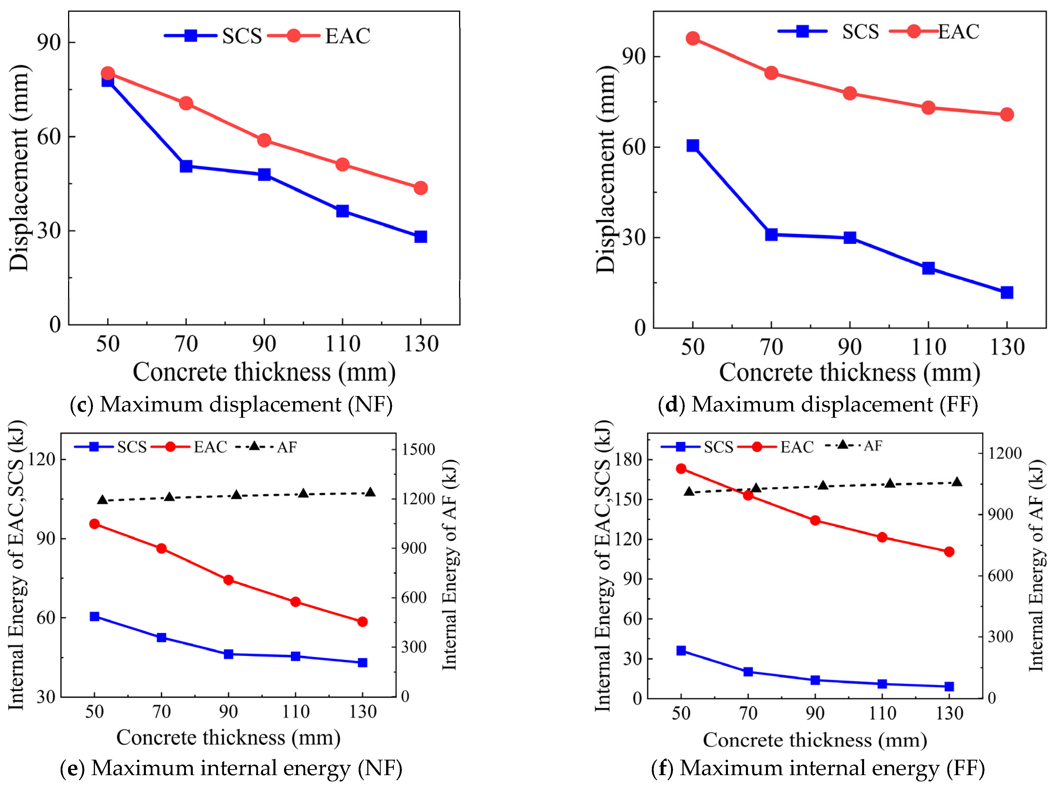
3.6.2. Effect of Concrete Thickness

The blast resistance of the SAFSCS-EAC door with varying concrete thicknesses was evaluated through numerical simulations. Each door was uniformly designed with the same parameters, differing only in concrete thickness values of 50, 70, 90, 110, and 130 mm. For the near field (NF) blast detonation, the doors were subjected to a 20 kg TNT load at a standoff distance of 750 mm, while in the far field blast they faced a 200 kg TNT load at a distance of 3000 mm. Figure 27 shows the dynamic response of the SAFSCS-EAC door under near and far field blasts with varying concrete thickness. Figure 27a,b show the time histories curve of the mid-span deflection of the SCS panel of the door with variant concrete thickness under near and far field blast loads and Figure 27c,d exhibit the maximum displacement of the SCS and the EAC, while the maximum internal energy of the SCS and the EAC under near and far field blasts are given in Figure 27e,f. Concerning the increase in concrete thickness in near field scenarios, the deflection peaks appear and tend to stabilize as time progresses, leading to a reduction in peak deflection. Conversely, in far field blasts, the deflection pattern exhibits more pronounced oscillations over time, indicating a more complex interaction between the blast wave and the door structure.
However, similarly to the NF results, increased concrete thickness correlates with reduced deflections, and the maximum mid-span deflection of the door significantly reduces, showing a decrease of 63.9% in near field scenarios and an even more substantial reduction of 80.5% in far field scenarios, underscoring the effectiveness of concrete in absorbing and dissipating blast energy. In correlation with the reduction in mid-span deflection, the displacement of the EAC also shows a marked decrease of 45.6% for near field blast and 36.3% for far field blast scenarios.
The internal energy absorbed by the SCS and EAC components decreases as the concrete’s thickness increases, as shown in Figure 27e,f. Specifically, the absorption decreases by 28.8% for the SCS and by 38.8% for the EAC in near field blasts and by 74.72% for the SCS and 36.13% for the EAC in far field blasts. Interestingly, the internal energy absorption of AF increases slightly by 3.9% for near field and 4.7% for far field blasts as the concrete’s thickness is increased, which is because thicker concrete adds mass and stiffness to the door’s assembly, which can slow the overall response of the door to blast loads. This delayed response allows the AF more time to engage fully with the incoming energy, undergoing progressive deformation rather than rapid, potentially less efficient compression. This gradual engagement helps maximize the energy absorption capabilities of the foam.
Selecting a moderate concrete thickness can significantly mitigate blast impacts without the added burden of excessive weight, ensuring that the door remains lightweight enough for practical use in various military applications. This strategy provides substantial protection against blasts while maintaining practical functionality. In engineering terms, the choice of medium thickness for concrete should be complemented by an optimal thickness of the EAC. This combination is designed to achieve the best balance between weight and performance. The EAC’s role in energy absorption and structural integrity becomes especially critical when trying to minimize the weight of the door, as it must effectively compensate for the reduced mass of concrete, thus ensuring that the door’s protective capabilities are not compromised.

4. Conclusions

This research proposed a new SAFSCS sandwich panel with the EAC between the door frame and the rigid frame. Blast simulations were performed to investigate the near and far field blast responses of the SAFSCS-EAC door. The effect of the crushing force of the EAC and the concrete core thickness was investigated. Based on these numerical studies, the major findings can be summarized as follows.
The response modes of the SAFSCS-EAC subjected to near and far field blast detonation can be grouped into three types. Response mode 1: The crushing force required for the EAC to be crushed is too large, and the EAC cannot be crushed during the blast process. Response mode 2: The SCS composite slab undergoes rigid body displacement under blast, triggering the crushing energy absorption of the EAC, and it has not reached the densification stage. Response mode 3: The EAC reaches the densification stage in near and far field blasts.
The failure and energy absorption mechanisms of the AF, SCS composite panel, and EAC in the SAFSCS-EAC composite door were analyzed. The face steel plate exhibited membrane stretching in both near and far field blast loading. The AF demonstrated local densification in near field blasts and global densification in far field blasts, absorbing most of the blast energy due to its cellular structure. For the SCS panel, near field blasts caused punching-like failure, while far field blasts led to global flexural failure. The EAC’s curved steel plates formed plastic hinges at the bends in response modes 2 and 3 for both near and far field blasts, effectively dissipating blast energy through rotation. In response mode 1, the EAC showed minimal plastic deformation and energy consumption. Additionally, the deflection of the SCS panel was reduced by 44.2% and 62.3% in response modes 2 and 3, respectively, in comparison with response mode 1, for near and far field blast detonations.
The SAFSCS-EAC door shows different responses under near and far field blasts with varying crushing forces of the EAC. The blast resistance performance of the SAFSCS-EAC door panel is increased with optimal thickness of EAC curved steel plates by ensuring that its maximum compression displacement is lower than full compaction. Additionally, the crushing force of the EAC is lower than the ultimate resistance of the SCS panel. Furthermore, the blast resistance of the SAFSCS-EAC door is increased with increased concrete core thickness. Selecting a moderate concrete thickness can significantly mitigate blast impacts without the added burden of excessive weight, ensuring that the door remains lightweight enough for practical use in various applications.
The results of this study have clear implications for practical engineering applications. Among the analyzed configurations, response mode 2, where the energy absorption connectors (EACs) undergo controlled plastic deformation without reaching full compaction, proved to be the most suitable for real-world use. This configuration provides a balanced trade-off between energy absorption and structural integrity by enabling the EAC to dissipate blast energy effectively while minimizing permanent damage to the SCS panel.

5. Limitations and Future Work

This study primarily relies on finite element simulations conducted in LS-DYNA to evaluate the blast resistance of the SAFSCS-EAC door panel. While the results offer critical insights into the structural response under blast loading, the lack of experimental work for the complete door system remains a limitation. Additionally, the TNT charges were assumed to detonate at the center of the door, and the supporting boundary conditions were idealized as infinitely rigid. These assumptions may not fully reflect real-world behavior. Moreover, the door panel was modeled as resting on the support frame without anchoring, which does not represent practical installation conditions, where doors are typically fixed or hinged. Future research should incorporate experimental testing, investigate off-center blast scenarios, consider deformable support conditions, and model realistic anchorage mechanisms to further validate and improve the proposed design.

Author Contributions

Conceptualization, S.A. and Y.W.; methodology, S.A., S.Z., M.U., and Y.W.; software, S.A.; validation, S.A., S.Z., and Y.W.; formal analysis, S.A.; investigation, S.A.; resources, S.A.; data curation, S.A.; writing—original draft preparation, S.A.; writing—review and editing, S.A.; visualization, Y.W.; supervision, Y.W.; project administration, Y.W.; funding acquisition, Y.W. All authors have read and agreed to the published version of the manuscript.

Funding

The research presented in this paper is financially supported by the National Natural Science Foundation of China (Grant no.: 52278166) and the Natural Science Foundation of Heilongjiang Province (Grant No. YQ2022E035).

Data Availability Statement

The datasets used and/or analyzed in the current study are available from the corresponding author upon reasonable request.

Conflicts of Interest

The authors declared no potential conflicts of interest with respect to the research, authorship, and/or publication of this article.

References

  1. Anderson, M.; Dover, D. Lightweight, Blast-Resistant Doors for Retrofit Protection against the Terrorist Threat. In Proceedings of the 2nd International Conference on Innovation in Architecture, Engineering and Construction, Loughborough, UK, 25–27 June 2003; pp. 23–33. [Google Scholar]
  2. Goel, M.D.; Matsagar, V.A.; Marburg, S.; Gupta, A.K. Comparative Performance of Stiffened Sandwich Foam Panels under Impulsive Loading. J. Perform. Constr. Facil. 2013, 27, 540–549. [Google Scholar] [CrossRef]
  3. Salomoni, V.A.; Mazzucco, G.; Xotta, G.; Fincato, R.; Majorana, C.E.; Schiavon, M. Nonlinear Modelling, Design, and Test of Steel Blast-Resistant Doors. Adv. Mech. Eng. 2013, 5, 908373. [Google Scholar] [CrossRef]
  4. Veeredhi, L.S.B.; Ramana Rao, N.V. Studies on the Impact of Explosion on Blast Resistant Stiffened Door Structures. J. Inst. Eng. India Ser. A 2015, 96, 11–20. [Google Scholar] [CrossRef]
  5. Choi, Y.; Lee, J.; Yoo, Y.-H.; Yun, K.-J. A Study on the Behavior of Blast Proof Door under Blast Load. Int. J. Precis. Eng. Manuf. 2016, 17, 119–124. [Google Scholar] [CrossRef]
  6. Chen, L.; Fang, Q.; Zhang, Y.-D.; Zhang, Y.; Fan, J.-Y. Numerical and Experimental Investigations on the Blast-Resistant Properties of Arched RC Blast Doors. Int. J. Prot. Struct. 2010, 1, 425–441. [Google Scholar] [CrossRef]
  7. Yan, Q.; Guo, D. Elastic Rebound of a Blast Door Under Explosion Loadings. Int. J. Str. Stab. Dyn. 2018, 18, 1871011. [Google Scholar] [CrossRef]
  8. Dong, S.; Tian, Z.; Cao, X.; Tian, C.; Wang, Z. Analysis of the Ultimate Load-Bearing Capacity of Steel-Clad Concrete-Filled Steel Tube Arched Protective Doors under Blast Shock Waves. Buildings 2023, 13, 1424. [Google Scholar] [CrossRef]
  9. Thimmesh, T.; Shirbhate, P.A.; Mandal, J.; Sandhu, I.S.; Goel, M.D. Numerical Investigation on the Blast Resistance of a Door Panel. Mater. Today Proc. 2021, 44, 659–666. [Google Scholar] [CrossRef]
  10. Hsieh, M.-W.; Hung, J.-P.; Chen, D.-J. Investigation on the Blast Resistance of a Stiffened Door Structure. J. Mar. Sci. Technol. 2008, 16, 7. [Google Scholar] [CrossRef]
  11. Chen, H.; Li, F. Design of Quadrilateral Zero-Poisson’s Ratio Metamaterial and Its Application in Ship Explosion-Proof Hatch Door. Ocean. Eng. 2022, 266, 112667. [Google Scholar] [CrossRef]
  12. Zhao, Z.; Zhang, B.; Zhou, J.; Chen, H.; Wang, B.; Zhou, Y.; Xu, Y.; Jin, F.; Fan, H. Quasi-Far-Field Blast Responses of Hierarchical Orthogrid-Stiffened Sheet Molding Compound (SMC) Protective Door Structures. Eng. Struct. 2018, 168, 431–446. [Google Scholar] [CrossRef]
  13. Meng, F.; Zhang, B.; Zhao, Z.; Xu, Y.; Fan, H.; Jin, F. A Novel All-Composite Blast-Resistant Door Structure with Hierarchical Stiffeners. Compos. Struct. 2016, 148, 113–126. [Google Scholar] [CrossRef]
  14. Guo, H.; Yuan, H.; Zhang, J.; Ruan, D. Review of Sandwich Structures under Impact Loadings: Experimental, Numerical and Theoretical Analysis. Thin-Walled Struct. 2024, 196, 111541. [Google Scholar] [CrossRef]
  15. Li, J.; Qin, Q.; Zhang, J. Internal Blast Resistance of Sandwich Cylinder with Lattice Cores. Int. J. Mech. Sci. 2021, 191, 106107. [Google Scholar] [CrossRef]
  16. Zhang, J.; Zhou, R.; Wang, M.; Qin, Q.; Ye, Y.; Wang, T.J. Dynamic Response of Double-Layer Rectangular Sandwich Plates with Metal Foam Cores Subjected to Blast Loading. Int. J. Impact Eng. 2018, 122, 265–275. [Google Scholar] [CrossRef]
  17. Zhang, J.; Qin, Q.; Wang, T.J. Compressive Strengths and Dynamic Response of Corrugated Metal Sandwich Plates with Unfilled and Foam-Filled Sinusoidal Plate Cores. Acta Mech 2013, 224, 759–775. [Google Scholar] [CrossRef]
  18. Wang, Y.; Zhai, X.; Lee, S.C.; Wang, W. Responses of Curved Steel-Concrete-Steel Sandwich Shells Subjected to Blast Loading. Thin-Walled Struct. 2016, 108, 185–192. [Google Scholar] [CrossRef]
  19. Wang, Y.; Lu, J.; Liu, S.; Zhai, X.; Zhi, X.; Yan, J.-B. Behaviour of a Novel Stiffener-Enhanced Steel–Concrete–Steel Sandwich Beam Subjected to Impact Loading. Thin-Walled Struct. 2021, 165, 107989. [Google Scholar] [CrossRef]
  20. Meng, L.; Wang, Y.; Zhai, X. Modeling and Dynamic Response of Curved Steel–Concrete–Steel Sandwich Shells Under Blast Loading. Int. J. Steel Struct. 2020, 20, 1663–1681. [Google Scholar] [CrossRef]
  21. Lan, S.; Lok, T.-S.; Heng, L. Composite Structural Panels Subjected to Explosive Loading. Constr. Build. Mater. 2005, 19, 387–395. [Google Scholar] [CrossRef]
  22. Zhao, C.; Chen, Y.; Jin, Q.; Wang, J.; Li, X. Blast Resistance of Single Steel-concrete Composite Slabs under Contact Explosion. Struct. Concr. 2023, 24, 6025–6048. [Google Scholar] [CrossRef]
  23. Zhao, C.; He, K.; Zhi, L.; Lu, X.; Pan, R.; Gautam, A.; Wang, J.; Li, X. Blast Behavior of Steel-Concrete-Steel Sandwich Panel: Experiment and Numerical Simulation. Eng. Struct. 2021, 246, 112998. [Google Scholar] [CrossRef]
  24. Yu, J.; Liang, S.-L.; Ren, Z.-P.; Deng, Y.-J.; Fang, Q. Structural Behavior of Steel-Concrete-Steel and Steel-Ultra-High-Performance-Concrete-Steel Composite Panels Subjected to near-Field Blast Load. J. Constr. Steel Res. 2023, 210, 108108. [Google Scholar] [CrossRef]
  25. Roberts, T.M.; Edwards, D.N.; Narayanan, R. Testing and Analysis of Steel-Concrete-Steel Sandwich Beams. J. Constr. Steel Res. 1996, 38, 257–279. [Google Scholar] [CrossRef]
  26. Schlaseman, C.; Russell, J. Application of Advanced Construction Technologies to New Nuclear Power Plants; US Department of Energy: Washington, DC, USA, 2004.
  27. Farhan, J.A.; Hussain, H.M. Development of Three-Layer Composite Steel-Concrete-Steel Beam Element with Applications. Eng. Technol. J. 2010, 28, 6970–6985. [Google Scholar] [CrossRef]
  28. Koh, C.G.; Ang, K.K.; Chan, P.F. Dynamic Analysis of Shell Structures with Application to Blast Resistant Doors. Shock Vib. 2003, 10, 269–279. [Google Scholar] [CrossRef]
  29. Chen, D.; Gao, K.; Yang, J.; Zhang, L. Functionally Graded Porous Structures: Analyses, Performances, and Applications—A Review. Thin-Walled Struct. 2023, 191, 111046. [Google Scholar] [CrossRef]
  30. Wang, G.; Zhang, Y.; Zheng, Z.; Chen, H.; Yu, J. Crashworthiness Design and Impact Tests of Aluminum Foam-Filled Crash Boxes. Thin-Walled Struct. 2022, 180, 109937. [Google Scholar] [CrossRef]
  31. Wang, S.; Zhang, M.; Pei, W.; Yu, F.; Jiang, Y. Energy-Absorbing Mechanism and Crashworthiness Performance of Thin-Walled Tubes Diagonally Filled with Rib-Reinforced Foam Blocks under Axial Crushing. Compos. Struct. 2022, 299, 116149. [Google Scholar] [CrossRef]
  32. Chakravarty, U.K. An Investigation on the Dynamic Response of Polymeric, Metallic, and Biomaterial Foams. Compos. Struct. 2010, 92, 2339–2344. [Google Scholar] [CrossRef]
  33. Yun, N.-R.; Shin, D.-H.; Ji, S.-W.; Shim, C.-S. Experiments on Blast Protective Systems Using Aluminum Foam Panels. KSCE J. Civ. Eng. 2014, 18, 2153–2161. [Google Scholar] [CrossRef]
  34. Ganorkar, K.; Goel, M.D.; Chakraborty, T. Numerical Analysis of Double-Leaf Composite Stiffened Door Subjected to Blast Loading. J. Perform. Constr. Facil. 2023, 37, 04022067. [Google Scholar] [CrossRef]
  35. Wang, Y.; Liew, J.R.; Lee, S.C. Experimental and Numerical Studies of Non-Composite Steel–Concrete–Steel Sandwich Panels under Impulsive Loading. Mater. Des. 2015, 81, 104–112. [Google Scholar] [CrossRef]
  36. Wang, Y.; Pokharel, R.; Lu, J.; Zhai, X. Experimental, Numerical, and Analytical Studies on Polyurethane Foam-Filled Energy Absorption Connectors under Quasi-Static Loading. Thin-Walled Struct. 2019, 144, 106257. [Google Scholar] [CrossRef]
  37. Harris, J.A.; McShane, G.J. Impact Response of Metallic Stacked Origami Cellular Materials. Int. J. Impact Eng. 2021, 147, 103730. [Google Scholar] [CrossRef]
  38. Baroutaji, A.; Gilchrist, M.D.; Olabi, A.-G. Quasi-Static, Impact and Energy Absorption of Internally Nested Tubes Subjected to Lateral Loading. Thin-Walled Struct. 2016, 98, 337–350. [Google Scholar] [CrossRef]
  39. Meng, L.; Wang, Y.; Zhai, X. Experimental and Numerical Studies on Steel-Polyurethane Foam-Steel–Concrete-Steel Panel under Impact Loading by a Hemispherical Head. Eng. Struct. 2021, 247, 113201. [Google Scholar] [CrossRef]
  40. Livermore Software Technology Corporation. LS-DYNA Keyword User’s Manual; LSTC Co.: Livermore, CA, USA, 2007. [Google Scholar]
  41. Abramowicz, W.; Jones, N. Dynamic Progressive Buckling of Circular and Square Tubes. Int. J. Impact Eng. 1986, 4, 243–270. [Google Scholar] [CrossRef]
  42. Murray, Y.D. Users Manual for LS-DYNA Concrete Material Model 159; US Department of Transportation, Federal Highway Administration: McLean, VA, USA, 2007.
  43. Castedo, R.; Santos, A.P.; Alañón, A.; Reifarth, C.; Chiquito, M.; López, L.M.; Martínez-Almajano, S.; Pérez-Caldentey, A. Numerical Study and Experimental Tests on Full-Scale RC Slabs under Close-in Explosions. Eng. Struct. 2021, 231, 111774. [Google Scholar] [CrossRef]
  44. Bruhl, J.C. Behavior and Design of Steel-Plate Composite (SC) Walls for Blast Loads. Ph.D. Thesis, Purdue University, West Lafayette, IN, USA, 2015. [Google Scholar]
  45. Wang, Y.; Liew, J.R.; Lee, S.C.; Wang, W. Experimental and Analytical Studies of a Novel Aluminum Foam Filled Energy Absorption Connector under Quasi-Static Compression Loading. Eng. Struct. 2017, 131, 136–147. [Google Scholar] [CrossRef]
  46. Wang, Y.; Zhai, X.; Wang, W. Numerical Studies of Aluminum Foam Filled Energy Absorption Connectors under Quasi-Static Compression Loading. Thin-Walled Struct. 2017, 116, 225–233. [Google Scholar] [CrossRef]
  47. Momeni, M.; Hadianfard, M.A.; Bedon, C.; Baghlani, A. Damage Evaluation of H-Section Steel Columns under Impulsive Blast Loads via Gene Expression Programming. Eng. Struct. 2020, 219, 110909. [Google Scholar] [CrossRef]
Figure 1. General illustration of the SAFSCS-EAC: (a) SAFSCS-EAC, (b) SAFSCS with frame, (c) EAC.
Buildings 15 02073 g001
Figure 2. Finite element model of SAFSCS-EAC door panel under blast loading.
Buildings 15 02073 g002
Figure 3. Input stress–strain curve in the FE model. (a) True stress–effective plastic strain curve for steel plates. (b) Stress–volumetric strain curve for aluminum foam.
Buildings 15 02073 g003
Figure 4. Experimental specimen design [44].
Buildings 15 02073 g004
Figure 5. Components of the FE model for validation.
Buildings 15 02073 g005
Figure 6. Collapse process of concrete core after shot 4 and shot 6.
Buildings 15 02073 g006
Figure 7. FE model of energy absorption connector. (a) FE model of energy absorption connector; (b) Test setup and instrumentation [45].
Buildings 15 02073 g007
Figure 8. Collapse process of the connectors (R = 75): (a) experimental [45] and (b) FEM results.
Buildings 15 02073 g008
Figure 9. Comparison of experimental and FEM results.
Buildings 15 02073 g009
Figure 10. Deformation process of SAFSCS-EAC composite door under near field blast.
Buildings 15 02073 g010
Figure 11. Deformation process of SAFSCS-EAC composite door under far field blast.
Buildings 15 02073 g011
Figure 12. Force, displacement, and internal energy time histories of SAFSCS-EAC40T20 obtained from FE simulations for response mode 1 near field blast.
Buildings 15 02073 g012
Figure 13. Force, displacement, and internal energy time histories of SAFSCS-EAC40T100 obtained from FE simulations for response mode 1 far field blast.
Buildings 15 02073 g013
Figure 14. Force, displacement, and internal energy time histories of SAFSCS-EAC12T20 obtained from FE simulations for mode 2 near field blast.
Buildings 15 02073 g014
Figure 15. Force, displacement, and internal energy time histories of SAFSCS-EAC12T100 obtained from FE simulations for mode 2 far field blast.
Buildings 15 02073 g015
Figure 16. Force, displacement, and internal energy time histories of SAFSCS-EAC6T20 obtained from FE simulations for mode 3 near field blast.
Buildings 15 02073 g016
Figure 17. Force, displacement, and internal energy time histories of SAFSCS-EAC6T100 obtained from FE simulations for mode 3 far field blast.
Buildings 15 02073 g017
Figure 18. Effective plastic strain contours of the faceplate of the SAFSCS-EAC composite door.
Buildings 15 02073 g018
Figure 19. Effective plastic strain contours of the aluminum foam of the SAFSCS-EAC composite door.
Buildings 15 02073 g019
Figure 20. Effective plastic strain contours of the concrete core of the SAFSCS-EAC door.
Buildings 15 02073 g020
Figure 21. Effective plastic strain contours of the bottom steel plate of the SCS panel.
Buildings 15 02073 g021
Figure 22. Permanent deflection of the bottom steel plate of the SCS panel.
Buildings 15 02073 g022
Figure 23. Effective plastic strain contours of curved steel plates of the EAC.
Buildings 15 02073 g023
Figure 24. Comparison of mid-span deflection of the SCS panel under TNT charges.
Buildings 15 02073 g024
Figure 25. Comparison of internal energy of each component with different TNT charges.
Buildings 15 02073 g025
Figure 26. Blast response of SAFSCS-EAC door with varying EAC thicknesses.
Buildings 15 02073 g026aBuildings 15 02073 g026b
Figure 27. Blast response of SAFSCS-EAC door with varying concrete thickness.
Buildings 15 02073 g027aBuildings 15 02073 g027b
Table 1. Parameters of the simulation model.
Blast TypeModelBlast Load TNT (kg)Standoff Distance (mm)Concrete (mm)Scale Distance (m/kg1/3)
Near field blastSAFSCS-EAC-612
16
20
550
650
750
70
70
70
0.24
0.26
0.28
SAFSCS-EAC-1212
16
20
550
650
750
70
70
70
0.24
0.26
0.28
SAFSCS-EAC-4012
16
20
1500
2000
3000
70
70
70
0.24
0.26
0.28
Far field blastSAFSCS-EAC-660
100
200
1500
2000
3000
70
70
70
0.39
0.44
0.52
SAFSCS-EAC-1260
100
200
1500
2000
3000
70
70
70
0.39
0.44
0.52
SAFSCS-EAC-4060
100
200
1500
2000
3000
70
70
70
0.39
0.44
0.52
Table 2. Material input for LS-DYNA models.
ComponentsMaterial ModelYield Strength (MPa)Ultimate Strength
(MPa)
Elastic Modulus
(GPa)
Steel plate of SCSPIECWISE_LINEAR_PLASTICITY
(MAT_024)
398472200
Curved steel plate298536204.6
EAC top and bottom steel plate363577217.7
Bolt410496144.8
Concrete
CSCM
(MAT_159)
Compressive strength
(MPa)
42.7
Elastic modulus
(GPa)
24.3
Poisson’s ratio

0.2
Aluminum foam
CRUSHABLE_FOAM
(MAT_063)
Young’s modulus
(MPa)
120
Plateau stress
(MPa)
2.69
Density
(g/cm3)
0.286
Table 3. Comparison of Bruhal’s experimental and FEM results.
PanelShotBruhal ExperimentalBruhal FEMFEM ResultsDifference
XMXMXM
(mm)(mm)(mm)(%)
3-2-50-5(1)14.62284.16564.1209812.18
5-2b-50-5(1)32.43842.43842.345283.97
5-2b-50-5(1)413.385813.436613.23831.11
5-2-50-5(2)613.995411.607813.13146.58
Table 4. Comparison of experimental and FEM mean force (kN).
Experimental Results
Mean Force (kN)
FEM Results
Mean Force (kN)
Difference
(%)
Mean force47.448.93.16
Table 5. Summary of near field blast analysis.
SpecimenTNT
Charge (kg)
Response ModeInternal Energy (kJ)δSCS (mm)ΔEAC
(mm)
AFSCSEAC
121927.368.518.286.7
SAFSCS-EAC-401611100.984.425.889.4
2011240.481.232.389.211.2
122925.567.454.856.4
SAFSCS-EAC-121621098.861.172.853.7
2021206.752.586.35671
123927.965.549.958.3
SAFSCS-EAC-61631100.762.163.953.9
2031208.555.574.350130
Table 6. Summary of far field blast analysis.
SpecimenTNT
Charge (kg)
Response ModeInternal Energy (kJ)δSCS (mm)ΔEAC
(mm)
AFSCSEAC
6011359.771.55259.492.3
SAFSCS-EAC-4010011300696890.211.2
20011030.866.568.387.2
6021358.327.7133.736.9
SAFSCS-EAC-121002129724.715035.583
20021026.420.3153.130.7
6031359.135.5113.534.7
SAFSCS-EAC-61003129837.711732.6120
20031027.335.1120.527.8
Note: “δ” represents the mid-span deflection of the SCS panel and “Δ” represents the compression displacement of the curved steel plates of the EAC.
Disclaimer/Publisher’s Note: The statements, opinions and data contained in all publications are solely those of the individual author(s) and contributor(s) and not of MDPI and/or the editor(s). MDPI and/or the editor(s) disclaim responsibility for any injury to people or property resulting from any ideas, methods, instructions or products referred to in the content.

