Article

Deformation Control of Shield Tunnels Affected by Staged Foundation Pit Excavation: Analytical Method and Case Study

1
Department of Civil Engineering, Hangzhou City University, Hangzhou 310015, China
2
Zhejiang Provincial Engineering Research Center of Intelligent Urban Infrastructure, Hangzhou 310015, China
3
Institute of Geotechnical Engineering, Zhejiang University of Technology, Hangzhou 310023, China
4
Zhejiang Province Institute of Architectural Design and Research, Hangzhou 310008, China
5
Department of Civil Engineering, Zhejiang University, Hangzhou 310058, China
*
Author to whom correspondence should be addressed.
Buildings 2025, 15(12), 2046; https://doi.org/10.3390/buildings15122046
Submission received: 8 May 2025 / Revised: 6 June 2025 / Accepted: 12 June 2025 / Published: 13 June 2025
(This article belongs to the Section Building Structures)

Abstract

The unloading effect induced by foundation pit excavation leads to soil deformation, which may adversely affect the underlying tunnel. Foundation pit excavation is a three-dimensional (3D) deformation process, whereas most existing methods are based on a two-dimensional (2D) plane assumption. To improve conventional 2D analysis methods, this study considers the influence of the actual construction sequence on tunnel deformation. A 3D analytical method for evaluating tunnel deformation and stress induced by foundation pit excavation is proposed, based on the image source method and the rotational dislocation-coordinated deformation model. The proposed method is validated through comparative analysis with other methods using monitoring data from three engineering cases. Furthermore, the study examines and discusses the impact of excavation sequences on the final longitudinal displacement of the tunnel. The results indicate that the proposed method provides more accurate predictions of tunnel deformation induced by foundation pit excavation in actual projects. Staged and segmented excavation reduces bottom heave of the foundation pit, thereby mitigating its impact on the underlying tunnel. When the segmentation efficiency is positive, increasing the number of excavation blocks contributes to better tunnel deformation control. However, when the segmentation efficiency is negative, an increase in excavation blocks has an insignificant effect on deformation control or leads to excessive construction workload.

1. Introduction

With the acceleration of urbanization, the development of underground space has become a crucial approach to alleviating traffic pressure and expanding urban functions [1]. However, foundation pit excavation, as a key stage in underground engineering, significantly disturbs the surrounding soil stress field, leading to deformation of adjacent shield tunnels and even posing threats to their structural safety and operational stability [2]. For instance, in a large-scale project, inaccurate deformation predictions resulted in tunnel segment cracking and water leakage, which further affected structural durability and operational safety [3,4,5]. Therefore, establishing a reliable theoretical model for deformation prediction, accurately forecasting and controlling such deformations, is of great practical significance for ensuring engineering safety.
At present, research methods on foundation pit-tunnel interaction mainly include: (1) field measurement analysis [6,7,8,9,10]; (2) numerical simulation [2,5,11,12,13,14]; (3) model tests [15,16,17]; and (4) theoretical solutions [18,19,20,21,22,23,24,25,26,27]. Theoretical solutions, based on elastic theory and soil structure interaction models, allow rapid assessment of deformation trends through closed-form solutions, providing essential guidance for practical construction. In terms of theoretical solutions, Liu et al. [18] adopted a two-parameter Vlasov foundation to simulate tunnel-soil interaction based on actual engineering cases. They demonstrated that when the vertical clearance between the foundation pit and tunnel is small, considering the influence of lateral soil on tunnel deformation response significantly improves prediction accuracy. Feng et al. [19] used the Mindlin solution to compute additional stress induced by excavation and modeled the tunnel as both an Euler-Bernoulli beam on a Winkler-Pasternak foundation and a Timoshenko beam on a three-parameter Kerr foundation. They derived governing differential equations for additional stress effects on tunnel response, obtaining tunnel internal forces and deformation. However, these methods involve excessive assumptions, complex boundary condition determination, and difficulties in parameter selection. Cheng et al. [21] considered the unloading effect of the pit’s sidewall and the shear effects of the soil surrounding the underlying shield tunnel. They simplified the shield tunnel as a Euler beam resting on a Pasternak foundation and used the Mindlin solution to compute additional stress due to excavation. A governing differential equation for tunnel deformation was formulated and solved using the finite difference method. Liang et al. [22] modeled the tunnel as a Timoshenko beam on a Pasternak foundation and established a two-stage solution method to analyze the impact of excavation depth and foundation reaction coefficient on tunnel deformation. Liu et al. [23] regarded the shield tunnel as a Timoshenko beam on a Vlasov foundation and analyzed the effects of excavation depth, soil stratification thickness, excavation sequence, and construction step length based on field monitoring data. Guan et al. [19] considered the combined effects of excavation and dewatering, using a Pasternak foundation and a Timoshenko beam model to examine the influence of pit dimensions, excavation depth, and groundwater drawdown on tunnel deformation. However, the above studies mostly approximate shield tunnels as homogeneous continuous beams, using equivalent bending stiffness to replace the effect of segmental joints, which fails to accurately capture actual tunnel deformation in engineering applications. Huang et al. [25] introduced a discontinuous foundation beam model that accounts for segment joint rotation and differential settlement displacement to analyze tunnel deformation induced by foundation pit excavation.
The image source method [28] has been investigated by several previous scholars. Xu et al. [29] extended the image source method by incorporating soil convergence non-uniformity, thereby deriving the horizontal soil displacement induced by foundation pit excavation. Yu Jianlin et al. [30] improved the conventional two-dimensional (2D) analytical approach and, based on the image source method, proposed an analytical method for evaluating the horizontal displacement and bending moment of adjacent pile foundations caused by excavation. Wei et al. [31] developed a 2D analytical solution for shield tunnel deformation due to foundation pit unloading, considering excavation width effects, which can be applied to relatively simple foundation pit conditions.
In summary, the image source method has been effectively utilized in research for predicting the environmental impact of foundation pit excavation, leveraging field monitoring data. However, most existing studies are based on 2D plane assumptions, while actual foundation pit excavation and tunnel deformation involve three-dimensional (3D) spatial deformation. To date, no applications of the 3D image source method in this field have been reported.
This study introduces the rotational dislocation-coordinated deformation model and incorporates the three-dimensional image source method, proposing a computational approach for evaluating the deformation of an underlying shield tunnel induced by foundation pit unloading under complex working conditions and construction sequences. The accuracy and reliability of the proposed method are validated by comparing the computed results with field measurements.

2. Establishment of Mechanical Model

2.1. Limitations of Existing Models

The theoretical calculation of the deformation impact of foundation pit excavation on the underlying shield tunnel is mainly based on a two-stage analysis method. In the first stage, the additional stress acting on the underlying tunnel or the additional deformation of the surrounding soil induced by excavation is calculated. In the second stage, the coordinated deformation equation of the tunnel and soil is established to determine the tunnel deformation caused by excavation. In current computational methods, the unloading at the foundation pit bottom is generally assumed to be a uniformly distributed load. However, the excavation process involves spatial effects, and the bottom heave of the pit inevitably influences the unloading magnitude. This assumption deviates significantly from reality. Moreover, the stress release at the pit bottom induced by excavation is difficult to verify, presenting certain limitations. On this basis, Wei et al. [31] applied the image source method to compute the impact of bottom heave on the deformation of the underlying tunnel. However, this method still has certain shortcomings.
The theoretical solutions currently have the following limitations:
  • In existing computational methods, the deformation of pit bottom heave is considered only in a two-dimensional plane, as shown in Figure 1. However, in reality, after excavation, the pit bottom heave forms a three-dimensional curved surface. Additionally, these methods only account for the effect of the excavation length L, while the excavation width B is not included in the calculation. This leads to significant discrepancies between theoretical assumptions and actual conditions, making it difficult to ensure computational accuracy.
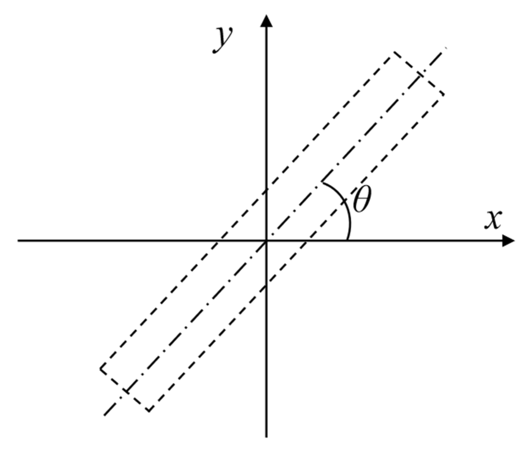
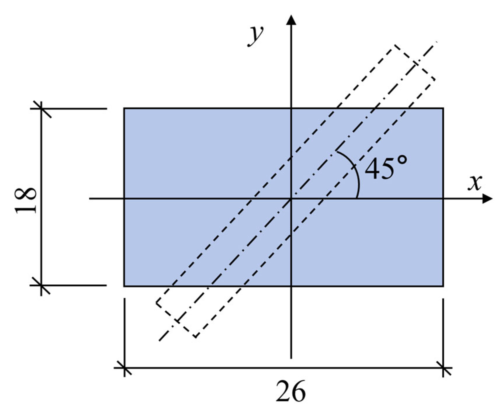
  • Current methods establish a coordinate system with the pit center as the origin, assuming that the underlying tunnel is orthogonal to the foundation pit. However, in actual subway tunnel planning, tunnels rarely cross perpendicularly beneath the pit and are more often obliquely intersecting, which is not adequately considered in existing models.
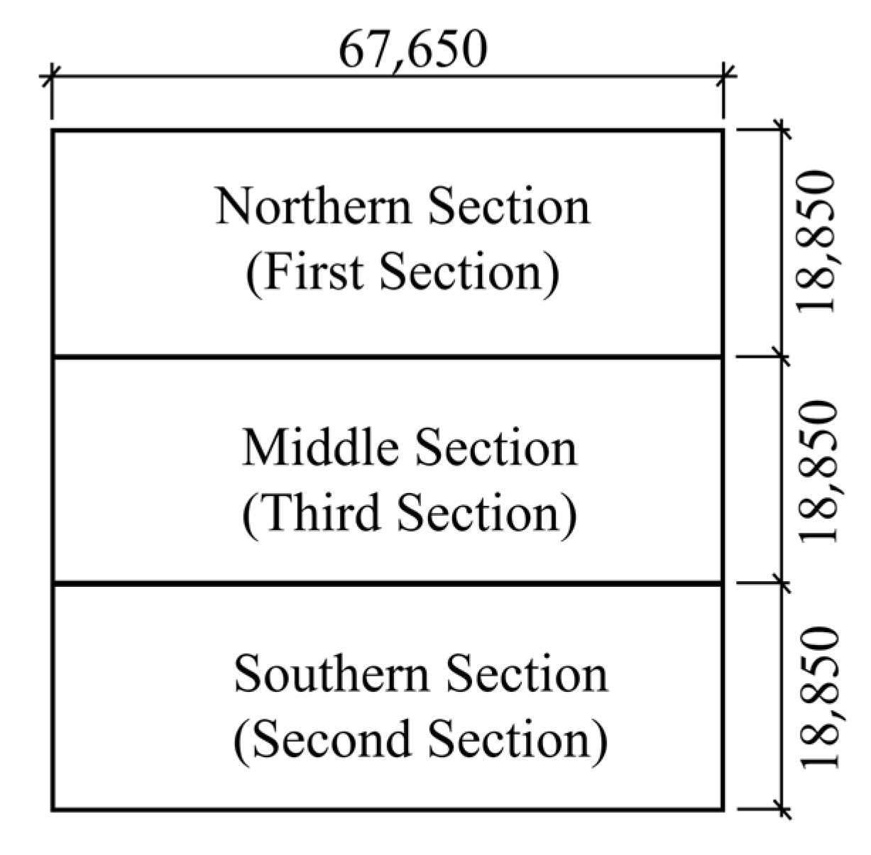
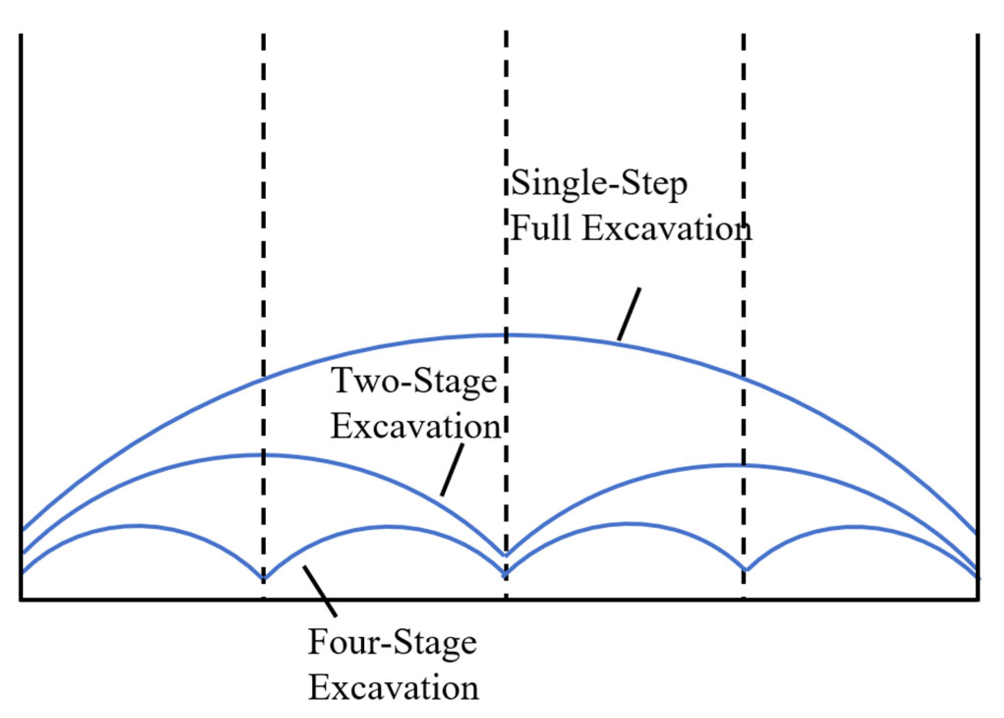
  • Existing methods often treat excavation as a single-step process, assuming that the foundation pit is excavated all at once. However, in real construction, excavation is typically carried out in stages and segments, which is not reflected in the current theoretical models, leading to discrepancies between calculations and actual construction sequences.
It should be noted that the proposed analytical method is based on several idealized assumptions. First, the soil is assumed to be linearly elastic, and plastic deformation, creep, and strain-softening behaviors are not considered. This simplification enables the derivation of closed-form solutions but may limit the applicability of the model under certain conditions, especially for deep excavations in soft soil layers where significant plastic deformation may occur. Furthermore, the model neglects the influence of pore water pressure dissipation and time-dependent soil behavior, which are critical in long-term excavation processes.
Therefore, the proposed method is more suitable for preliminary deformation prediction and comparative analysis of excavation sequences. For high-precision deformation prediction in soft ground, numerical simulations incorporating advanced constitutive models should be employed in conjunction with the analytical approach.

2.2. Improvements to Address the Identified Limitations

To overcome the shortcomings of existing theoretical solutions, this study proposes the following improvements:
(1)
Introducing a Three-Dimensional Pit Bottom Heave Model
Instead of assuming a 2D plane deformation, a 3D curved surface model is introduced to more accurately represent the actual deformation characteristics of pit bottom heave after excavation.
The excavation width B is incorporated into the calculation model, ensuring that both the length L and width B of the pit contribute to the deformation analysis.
The three-dimensional image source method is adopted to better simulate the stress redistribution in the soil surrounding the excavation, improving the accuracy of additional stress estimation.
(2)
Considering Arbitrary Tunnel Crossing Angles
The traditional assumption that the tunnel is orthogonal to the foundation pit is revised. Instead, a generalized coordinate system is introduced to accommodate tunnels that cross obliquely beneath the excavation.
The model is extended to account for different tunnel alignment angles, ensuring applicability to real-world subway planning, where tunnels rarely cross perpendicularly.
(3)
Incorporating Multi-Stage and Segmented Excavation Sequences
Instead of assuming that the excavation is completed in a single step, the model is modified to simulate staged and segmented excavation in alignment with actual construction processes. The influence of excavation sequence, step length, and excavation order on tunnel deformation is explicitly considered.
The interaction between excavation unloading and tunnel deformation at each stage is incorporated to improve prediction accuracy.
These improvements enhance the practicality and accuracy of the theoretical model, ensuring better alignment with actual construction conditions and providing more reliable predictions of tunnel deformation induced by foundation pit excavation.

3. Formula Derivation

As shown in Figure 2, the excavation length along the tunnel direction is L, the excavation width perpendicular to the tunnel axis is B, and the excavation depth is d. A coordinate system is established with the center of the excavation as the origin. The tunnel is located beneath the foundation pit, with an outer diameter of D and an axis burial depth of z0.

3.1. Calculation of Pit Bottom Heave Deformation

Many scholars, both domestically and internationally, have conducted research on the calculation methods for foundation pit rebound deformation [32]. The main research methods involve analyzing the same case using various approaches, including the traditional estimation method, new estimation method, empirical formula method, residual stress method, self-weight offset method, and numerical analysis method.
By comparing the calculated results with measured data, it has been concluded that the numerical analysis method provides the most accurate results, closely matching field measurements. The new estimation method ranks second in accuracy. However, the numerical analysis method requires a detailed model for each foundation pit, making it computationally intensive. In contrast, the new estimation method is more convenient and efficient while maintaining relatively high accuracy.
The new estimation method was specifically proposed by Zai [33], who derived a simplified formula for estimating foundation pit rebound based on elastic half-space stress solutions. The formula is as follows:
S 0 = 0.732 Q 1 μ 0 2 E 0
The rebound displacement at the excavation boundary is:
S 1 = 1 . 198 1 μ 0 0 . 0454 1 + μ 0 2 Q π E 0
where: S0 is the maximum rebound displacement at the pit bottom; S1 is the rebound displacement at the excavation boundary; Q is the total unit thickness weight of the soil, given by Q = LBdγ; γ is the unit weight of the soil within the excavation range; μ0 is the Poisson’s ratio of the soil; E0 is the soil rebound modulus, where in soft soil regions, the empirical value of E0 is approximately (3∼5)Es; Es is the soil compression modulus.
Figure 3 illustrates the relationship between the assumed semi-circular excavation profile and the actual rectangular excavation cross-section. When half of the excavation width or excavation depth exceeds the equivalent semi-circle radius, the actual pit bottom rebound displacement tends to be underestimated.
Therefore, width correction factor Y1 and depth correction factor Y2 are introduced:
Y 1 = L B 4 R 2 , Y 2 = d R
Thus, the corrected maximum rebound displacement Sr and the rebound displacement at the excavation boundary Sm are given as:
S r = Y 1 Y 2 S 0 , S m = Y 1 Y 2 S 1
Chinese and international scholars have conducted research on the shape of pit bottom heave induced by foundation pit excavation [34,35]. Zhang [34] conducted extensive experiments and concluded that when the excavation dimensions are relatively small, the bottom heave exhibits a symmetric “convex” shape. By comparing with other studies, consistent conclusions were obtained. Feng [35] utilized a 3D analytical model, incorporating three-dimensional spatial effects of excavation, and found that the bottom heave shape resembles an ellipsoid. Wei et al. [31] proposed that, in a 2D plane, when the excavation width is relatively small, the bottom heave follows a parabolic shape.
Based on these findings, this study assumes that the pit bottom heave follows a paraboloid shape, as shown in Figure 4. The heave at the center is denoted as Sr, while the heave at the pit sides is denoted as Sm. Beyond the paraboloid surface, in the corner areas of the pit, the heave value is assumed to be Sm. The equation describing the bottom heave surface is:
z r = S r 4 S r S m x 2 B 2 + y 2 L 2 x 2 B 2 + y 2 L 2 1 S m e l s e
In practical engineering, large foundation pits are often excavated using the staged excavation method, where the pit is divided into sections that are excavated separately. The next section is only excavated after the completion of the base slab in the previous section.
This study considers the staged excavation method, where a large foundation pit is divided into multiple smaller pits. Within each small pit, the bottom heave deformation follows the previously established formula. The overall impact on the tunnel due to the entire excavation process is then obtained by algebraically summing the individual effects of all small pits.

3.2. Calculation of Soil Displacement at the Tunnel Axis

C. Sagaseta [28] derived the vertical and horizontal soil displacements at any point within a semi-infinite elastic space due to soil loss (image source method) based on elastic assumptions.
In this study, the same method is applied to compute soil displacement induced by foundation pit excavation, with the following assumptions:
  • Soil compressibility, softening, and rheological effects are not considered.
  • Soil loss is the primary cause of soil displacement.
As shown in Figure 5, the displacement component along the z-axis at point P on the tunnel axis, caused by a void of radius a at point F, is given by:
S z 1 = a 3 3 z 0 d r 1 3
where: r 1 = x 0 x 1 2 + y 0 y 1 2 + z 0 d 2 , r1 is the distance between point F and point P.
Equation (6) is derived under the assumption of a full-space condition, whereas in reality, the problem involves a half-space domain.
To account for this, point F is mirrored to F’, as shown in Figure 6. The displacement component along the z-axis at point P, caused by the mirror point F’, is given by:
S z 2 = a 3 3 z 0 + d r 2 3
where: r 2 = x 0 x 1 2 + y 0 y 1 2 + z 0 + d 2 , r2 is the distance between mirror point F′ and point P.
Since this study assumes that soil compressibility is not considered, the additional shear stress field is assumed to have no effect on soil deformation.
Thus, the total displacement component along the z-axis at any point P, caused by a void of radius a at point F, is given by:
S z = S z 1 + S z 2 = a 3 3 z 0 d r 1 3 z 0 + d r 2 3
According to the volume equivalence principle, the pit bottom heave deformation is divided into n small rectangular elements. Each rectangular volume is then converted into an equivalent sphere, with the equivalent radius given by:
a = 3 d z r 4 π d x 1 d y 1 3
After obtaining the soil deformation at any point on the tunnel axis induced by soil loss at any point on the pit bottom, integration along the width direction of the pit bottom yields the vertical soil displacement at any point on the tunnel axis:
S z x 0 , y 0 = L / 2 L / 2 B / 2 B / 2 d z r 4 π z 0 d r 1 3 z 0 + d r 2 3 d x 1 d y 1
For any specific tunnel, the tunnel axis can be regarded as a line in the xy-coordinate system, thus satisfying the following equation:
y 0 = b x 0 + c
where: b = tanθ, where θ is the angle between the tunnel axis and the x-axis, as shown in Figure 7; c is a constant.
In Equation (10), x1 can be expressed in terms of y1, i.e.:
x 0 = y 0 c b
S z y 0 = S z y 0 c b , y 0 = L / 2 L / 2 B / 2 B / 2 d z r 4 π z 0 d r 1 3 z 0 + d r 2 3 d x 1 d y 1
Equation (13) depends only on y0, which geometrically means projecting the inclined line onto the y-axis for calculation. After obtaining the result, coordinate transformation can be applied to derive the displacement along the inclined tunnel axis:
y = y 0 cos θ
where: y′ is the actual horizontal coordinate.

3.3. Calculation of Longitudinal Deformation of the Underlying Tunnel

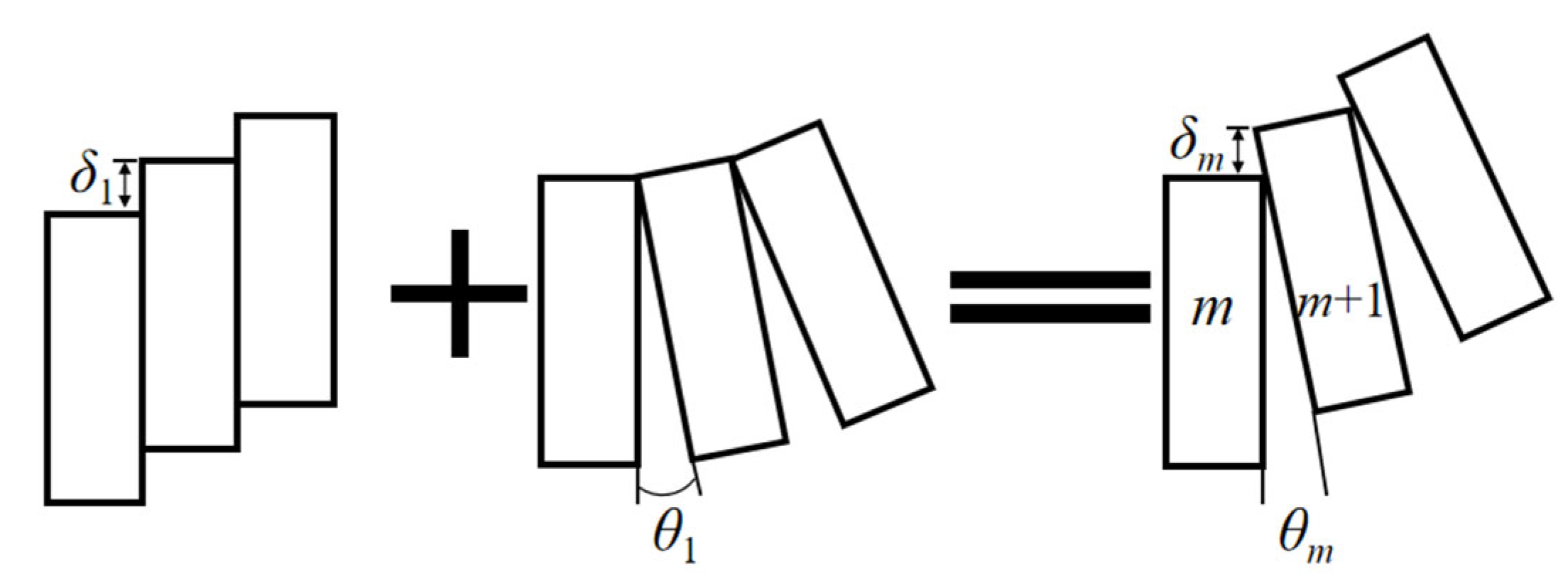
3.3.1. Consideration of the Rotational Dislocation-Coordinated Deformation Model [36]

To accurately describe the longitudinal deformation of the underlying tunnel, this study incorporates the rotational dislocation-coordinated deformation model, which accounts for:
Segmental Joint Rotation: Shield tunnels are composed of precast segments connected by joints, which allow rotational movement under external forces. The tunnel lining experiences bending and shear deformations, leading to joint opening and closing effects.
Differential Settlement and Dislocation: Uneven foundation pit heave induces differential settlement along the tunnel axis. This results in segmental dislocation, where adjacent segments exhibit relative vertical offsets (stepping displacement) at the joints.
Coordinated Deformation Mechanism: The combined effects of rotation and differential settlement lead to a nonlinear deformation mode. The interaction between joint stiffness, soil support, and loading conditions determines the tunnel’s overall deformation response.
As shown in Figure 8, the relative vertical displacement between segment mmm and segment m + 1 is denoted as δm. This displacement consists of two components:
  • δm1: The relative vertical displacement caused by segmental rotation.
    δm2: The relative vertical displacement caused by segmental dislocation (stepping effect).
Thus, the total displacement can be expressed as:
δm = δm1 + δm2
Defining j as the rigid-body rotational effect ratio of the segmental ring, which represents the percentage of the total relative vertical displacement attributed to rotational movement, we have:
δm1 = m
Assuming that the soil and tunnel satisfy the deformation coordination condition, the tunnel deformation at a given location is equal to the soil deformation at the same position, i.e.:
wt(l) = w(l)
where: wt(l) is the tunnel displacement at position l; w(l) is the soil displacement at the same position due to excavation-induced deformation; l is the y0 coordinate of any point along the longitudinal axis of the tunnel.
The relative vertical displacement between segments is given by the difference in vertical displacement between adjacent tunnel segments:
δ m = w t m + 1 D t w t m D t = w m + 1 D t w m D t
where: Dt is the ring width of the tunnel segment.
The shear force between adjacent tunnel rings is given by:
F s m = k s δ m 2 = 1 j k s δ m
The bolt tensile force is given by:
F t m = k t θ m D
The subgrade reaction force exerted on the tunnel in a Winkler foundation is given by:
F k = k D w l
In Equations (19)–(21), ks and kt are the shear stiffness and tensile stiffness of the tunnel segment joints, respectively, with calculation methods referenced from Guo Le et al. [37]. w(l) represents the longitudinal soil settlement or heave along the tunnel direction. k is the subgrade reaction coefficient, calculated using the formula from A.B. Vesic [38]:
k = 0.65 E s D 1 μ 0 2 E s D 4 E t I t 12
where: Es is the elastic modulus of the soil, D is the tunnel diameter, μ0 is the Poisson’s ratio of the soil, and EtIt is the equivalent bending stiffness of the tunnel, with the calculation method referenced from [36].

3.3.2. Total Potential Energy of Shield Tunnel Deformation

The total potential energy of deformation consists of the following four components:
1.
Work Done by Additional Load Due to Soil Deformation:
W L = m = N N 1 m D t m + 1 D t w l P l d l = N D t N D t w l P l d l
where: 2N represents the number of tunnel rings within the affected range; P(l) is the additional load induced by soil deformation at tunnel axis position l, given by:
P l = k S z l D
2.
Work Done to Overcome Subgrade Reaction Force
W R = m = N N 1 m D t m + 1 D t 1 2 w l k D w l d l = N D t N D t 1 2 D w l 2 d l
3.
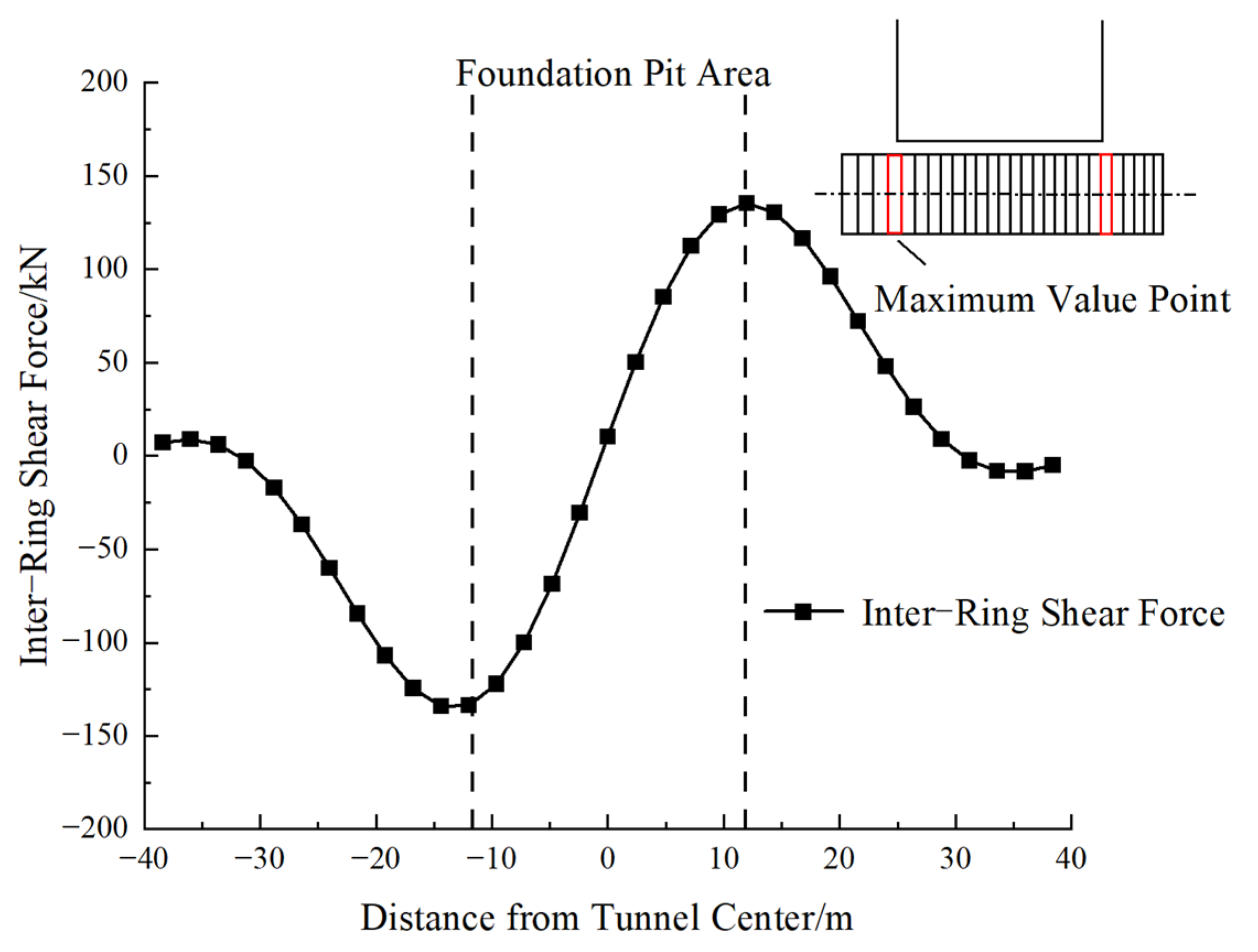
Work Done to Overcome Inter-Ring Shear Force
W S = m = N N 1 1 2 k s 1 j 2 w m + 1 D t w m D t 2
4.
Work Done to Overcome Bolt Tension
W T = m = N N 1 k t j 2 D 2 6 D t 2 w m + 1 D t w m D t 2

3.3.3. Fourier Expansion of the Longitudinal Displacement Function of Shield Tunnel

To express the longitudinal displacement function of the shield tunnel, Fourier series expansion is applied. The tunnel deformation function w(l), which represents the vertical displacement along the tunnel axis, can be expressed as:
w l = a 0 + n = 1 a n cos n π l N D t = T n l A T
where: T n l = 1       cos π l N D t       cos 2 π l N D t             cos n π l N D t A = a 0 , a 1 , a 2 , , a n T ; n is the order of the expansion terms in the Fourier series.

3.3.4. Solution of the Variational Control Equation

To determine the longitudinal deformation of the shield tunnel, the variational principle is applied to minimize the total potential energy Ep. The functional form of Ep is given by:
E p = W L + W R + W S + W T
where: WL, WR, WS, and WT are the energy terms derived previously.
The deformation function satisfies the Euler-Lagrange equation, derived by taking the first variation of Ep:
E p a i = W L a i + W R a i + W W a i + W T a i = 0
which leads to the governing variational equation:
m = N N 1 k s 1 j 2 + k t j 2 D 2 3 D t 2 w m + 1 D t w m D t a i T n m + 1 D t T n m D t + N D t N D t k D w l a i T n l d l A T = N D t N D t P l T n l T d l
The above equation can be expressed in matrix form as:
K r + K s A T = P T
K r = m = N N 1 k s 1 j 2 + k t j 2 D 2 3 D t 2 w m + 1 D t w m D t a i T n m + 1 D t T n m D t
K s = k D N D t 2 1 1
P T = N D t N D t P l T n l T d l
From the above equation, it follows that:
A T = K r + K s 1 P T
Substituting AT back into the equation yields the longitudinal displacement function of the tunnel:
w l = T n l A T
The stepping displacement between adjacent shield tunnel segments is given by:
δ m 2 = 1 j w m + 1 D t w m D t
The shear force between adjacent shield tunnel segments is given by:
Q m = 1 j w m + 1 D t w m D t k t
The above computational process is performed using MATLAB R2022b. In the integration steps, the composite Simpson’s numerical integration method is applied. For the numerical examples in this study, the parameters are referenced from [36]. The matrix orders of [Kr] and [Ks] are both set to 10 in the analysis.
When considering staged excavation of the foundation pit, each excavation section is treated as an independent small foundation pit. A coordinate system is established with the center of each small foundation pit as the origin. The tunnel displacement induced by the excavation of each section is computed as w(l)i. By algebraically summing the tunnel displacement contributions from all excavation sections, the total tunnel deformation W(l) and the corresponding internal forces can be obtained:
W l = i = 1 n w l i

4. Case Study Analysis

To verify the accuracy of the proposed calculation method, this section computes the vertical displacement curves of the underlying shield tunnel induced by foundation pit excavation in three real engineering cases and compares them with the original image source method and measured displacement curves. Since the original image source method requires the tunnel to be orthogonal to the foundation pit walls, only Case 2 and Case 3 are used for comparison.

4.1. Engineering Case 1

The Dongfang Road Underground Crossing Project is located in Pudong New Area, Shanghai [7]. The N01 section of the foundation pit is situated directly above a segment of Shanghai Metro Line 2, with a crossing angle of 45°. The distance between the tunnel crown and the foundation pit bottom is 2.76 m. The N01 foundation pit is 26 m long, 18 m wide, and 6.5 m deep. The tunnel has an outer diameter of 6.2 m and a lining thickness of 0.35 m. The tunnel calculation parameters are ks = 7.45 × 10⁵ kN/m, kt = 1.94 × 10⁶ kN/m, and EtIt = 1.1 × 10⁸ kN·m2. The soil parameters are shown in Table 1. The foundation pit excavation was carried out in small strips and sections, with the excavation method referenced from [39]. The relative positions of the foundation pit and the tunnel are shown in Figure 9.
Figure 10 compares the tunnel heave values obtained using the proposed calculation method, the Huang Maosong method [7], the Ni Yuping method [39], and the measured values. In this case, N = 60 and j = 0.2. As shown in Figure 7, compared to the measured maximum tunnel heave of 2.3 mm, the proposed method yields a prediction of 2.4 mm, corresponding to a relative error of only 4.3%. In contrast, the Huang Maosong method and Ni Yuping method yield predictions of 3.8 mm and 3.4 mm, with relative errors of 33.2% and 26.8%, respectively. These results demonstrate that the proposed method provides significantly improved accuracy in predicting tunnel deformation compared to existing analytical approaches.
To further quantify the agreement between the proposed analytical results and field measurements, the coefficient of determination (R2) was calculated. The R2 value of 0.982 indicates excellent consistency between the predicted and observed tunnel deformation in Case 1.
Figure 11 presents the segment stepping displacement and inter-ring rotation angle distribution. The segment stepping displacement and inter-ring rotation angle exhibit a centrally symmetric pattern. Zhang et al. [40] classified the safety assessment levels for stepping displacement and rotation angles. In Case 1, the maximum inter-ring rotation angle and maximum stepping displacement are 0.04 × 10⁻³ rad and 0.23 mm, respectively, corresponding to Level III, indicating a certain safety risk. The maximum stepping displacement and rotation angle occur at approximately ±12 m from the tunnel center, near the edge of the excavation area.
Figure 12 illustrates the inter-ring shear force distribution of the tunnel. Since inter-ring shear force is the primary cause of segment stepping displacement, the maximum stepping displacement coincides with the maximum inter-ring shear force, following the same distribution pattern. The maximum inter-ring shear force is 135 kN, which, according to the safety evaluation standard, is classified as Level I, indicating a safe condition.
As shown in Figure 11 and Figure 12, the maximum inter-ring shear force is 135 kN, which coincides with the maximum stepping displacement of 0.23 mm. This alignment supports the conclusion that segmental shear force is the primary driver of inter-ring vertical dislocation. The symmetrical distribution of both shear force and stepping displacement around the excavation center further confirms their strong correlation.

4.2. Engineering Case 2

A rapid transit tunnel in Hangzhou starts west of Dongxi Avenue and ends east of Jucheng Road, with a total length of 6240 m. In the section from Hengqiao Port to the segment endpoint (K3 + 010 to K3 + 630), a long strip-shaped foundation pit is present [6]. The excavation depth of the foundation pit is 10 m, and the width is 29.3 m. Due to the significant length of the foundation pit, a 43.8 m-long section directly above the tunnel is selected as the calculation region. The distance between the tunnel crown and the foundation pit bottom is 3.5 m. The tunnel calculation parameters are ks = 7.45 × 10⁵ kN/m, kt = 1.94 × 10⁶ kN/m, and EtIt = 1.1 × 10⁸ kN·m2. The soil calculation parameters are listed in Table 2. The foundation pit excavation is conducted in a staged manner, with the specific excavation sequence referenced from [6].
In this case, the tunnel is approximately orthogonal to the foundation pit, allowing the use of the traditional two-dimensional image source formula for calculation. As shown in Figure 13, the computed and measured longitudinal displacement values for the up-line and down-line tunnels are compared. The rigid-body rotational effect ratio is set to j = 0.2, N = 200. Compared to Case 1, Case 2 features two tunnels (up-line and down-line), which are symmetrically distributed relative to the foundation pit. Both measured and computed results indicate that the displacement values for the two tunnels are nearly identical. Therefore, the up-line tunnel is taken as an example for discussion. The proposed method calculates a maximum tunnel segment longitudinal heave of 3.7 mm, while the 2D image source method yields 10.4 mm, which shows a significant deviation from the measured values. The patterns of segment stepping displacement, rotation angle, and shear force are consistent with those in Case 1 and are not repeated here.

4.3. Engineering Case 3

The Nanning Rail Transit Line 4 Nahong Interchange Station No. 2 Ventilation Shaft and Entrance Foundation Pit [8] has an excavation depth of 9 m and a plan dimension of 67.65 m × 56.55 m. The foundation pit orthogonally crosses over the shield tunnel, with a tunnel outer diameter of 5.4 m, thickness of 0.3 m, and a distance of only 1.8 m from the tunnel crown to the foundation pit bottom. The main part of the foundation pit is located above tunnel rings 313–512. The tunnel calculation parameters are ks = 7.45 × 10⁵ kN/m, kt = 1.94 × 10⁶ kN/m, EtIt = 1.1 × 10⁸ kN·m2.
As shown in Figure 14, the foundation pit is excavated in sections, divided into three construction zones. The first and second sections on the north and south sides are excavated simultaneously. After the base slabs of Section 1 and Section 2 are completed, the middle third section is excavated. The excavation of Section 1 and Section 2 is defined as Phase 1, while the excavation of Section 3 is defined as Phase 2. As shown in Figure 15, the impact of Phase 1 excavation (Section 1 and Section 2) on tunnel displacement is analyzed, followed by a comparison of tunnel displacement after the completion of Phase 1 and Phase 2.
In this case, the tunnel is orthogonal to the foundation pit, allowing the use of the two-dimensional image source method for calculation. As shown in Figure 16, the calculated values from the proposed method, the two-dimensional image source method, and the measured values are compared. Within the excavation area (±28 m), the results from the proposed method closely match the measured values. Outside the excavation area, the two-dimensional image source method provides a better fit. The maximum longitudinal tunnel heave computed by the proposed method is 16.8 mm, while that computed by the two-dimensional image source method is 20.57 mm.

5. Discussion

The excavation sequence significantly influences the magnitude and distribution of tunnel displacement. Different excavation methods and sequences affect the stress redistribution in the surrounding soil, thereby altering the deformation behavior of the tunnel. In staged excavation, where sections are excavated one after another, the tunnel displacement develops gradually, reducing sudden deformations. In simultaneous excavation, larger stress release occurs at once, potentially leading to greater tunnel deformation. The sections excavated first determine the initial stress redistribution in the soil, which affects how subsequent excavation stages influence the tunnel. If sections near the tunnel are excavated first, a larger displacement may occur due to immediate unloading effects. Case studies indicate that excavation starting from the sides and moving toward the center results in smaller tunnel deformations compared to excavation from the center outward. Segmented excavation in smaller steps generally results in more controlled tunnel displacement than large-scale single-step excavation.
By analyzing the impact of different excavation processes on tunnel displacement, an optimal excavation sequence can be selected to minimize tunnel deformation and ensure structural safety.
From Case 2 and Case 3, it can be observed that the two-dimensional image source method treats foundation pit excavation as a single-step process, assuming that the entire pit is excavated at once. However, in actual construction, such an approach is generally avoided because simultaneous full excavation would cause a large release of stress at the pit bottom, leading to greater heave displacement and increased disturbance to the underlying tunnel.
In practical engineering, a staged and segmented excavation method is typically adopted. After completing excavation and casting the base slab in one section, the next section is excavated. Based on actual excavation procedures, this study divides a large foundation pit into multiple small pits, where each small pit produces less bottom heave than a large single excavation. As a result, the two-dimensional image source method tends to overestimate the heave displacement, leading to larger computed tunnel deformation compared to actual conditions.
As shown in Figure 17, the effect of staged and segmented excavation on foundation pit bottom heave is analyzed. After two-stage excavation, both the maximum heave and excavation boundary rebound are lower than those of single-step excavation, resulting in a lower total heave displacement. After four-stage excavation, the heave displacement is further reduced significantly.
Figure 17 illustrates the schematic effect of segmented excavation on the distribution of foundation pit bottom heave. The horizontal plane represents the plan view of the excavation area in the X–Y directions, while the vertical axis qualitatively indicates the magnitude of bottom heave (Z direction). As the excavation progresses from single-stage to multi-stage schemes, both the central heave and rebound at the excavation boundaries are reduced. This schematic demonstrates that increasing the number of excavation stages helps to mitigate uplift deformation at the pit base.
Taking Case 2 as an example, the foundation pit dimensions are 43.8 m × 29.3 m, and it is divided into 20 excavation blocks. When excavated in a single step, the maximum pit bottom heave is 22.9 mm, and the boundary rebound is 22.5 mm. In actual construction, the largest excavation block (III-①) measures 12.8 m × 6.0 m, with a maximum heave of 6.7 mm and a boundary rebound of 6.5 mm. The remaining blocks are smaller, producing even less heave and tunnel deformation. By superimposing the deformation contributions from all 20 excavation blocks, the final tunnel displacement is lower than that of single-step excavation.
Thus, in Case 2, the two-dimensional image source method significantly overestimates tunnel deformation compared to actual measurements. In Case 3, where the foundation pit is divided into three excavation sections, the difference between the two-dimensional image source method and the measured values is approximately 20%. This indicates that for practical engineering applications, the two-dimensional image source method no longer provides sufficiently accurate results for construction needs.
In Case 2, the foundation pit is divided into segments along both the length L and width B directions, with segment numbers Mn set to 1, 4, 9, 16, and 25. As shown in Figure 18, the maximum bottom heave Sr and boundary rebound Sm decrease as the number of segments increases. The rate of reduction is initially fast and then slows down. For four-stage excavation, the maximum pit bottom heave is 5.7 mm. For five-stage excavation, the maximum pit bottom heave is 4.5 mm, representing a 21% reduction.
As shown in Figure 19, the effect of different segmentation numbers on tunnel displacement is analyzed. As the number of excavation blocks increases, tunnel displacement follows a similar decreasing trend to that of pit bottom heave. This demonstrates that increasing the number of excavation blocks in a controlled manner can effectively reduce excavation-induced disturbances on the underlying tunnel.
As shown in Figure 18, increasing the number of excavation blocks significantly reduces the tunnel displacement. Compared to the single-stage excavation, four-stage excavation reduces the maximum tunnel displacement by approximately 45%, while nine-stage and 16-stage excavations reduce it by 62% and 74%, respectively. However, the rate of reduction gradually diminishes, indicating a nonlinear benefit.
When the number of blocks increases to 25, the additional reduction in tunnel displacement is marginal (less than 5% compared to the 16-block case), while the excavation complexity and construction cost increase substantially. Therefore, considering both deformation control and construction feasibility, the optimal number of sections may lie between nine and 16 for this case.
In this study, the subsurface soil is idealized as horizontally layered and homogenous within each layer, as presented in Table 1. This simplification facilitates analytical modeling and parameter calibration. However, it is well established that natural soils exhibit significant three-dimensional spatial variability, including intra-layer heterogeneity and spatial autocorrelation [41].
Such spatial variability can have a considerable impact on tunnel deformation and the ground response to adjacent foundation pit excavation. The current model does not account for these effects, which may lead to deviations from the actual deformation mechanism, particularly in complex geotechnical settings. Future improvements may incorporate random field theory or stochastic methods to better capture the influence of spatial variability in soil properties.

6. Conclusions

This study investigates the longitudinal deformation of an underlying shield tunnel induced by foundation pit excavation, considering the effects of segmental joint rotation and differential settlement. A rotational dislocation-coordinated deformation model is introduced, incorporating the three-dimensional image source method to enhance the accuracy of tunnel deformation prediction.
The main conclusions are as follows:
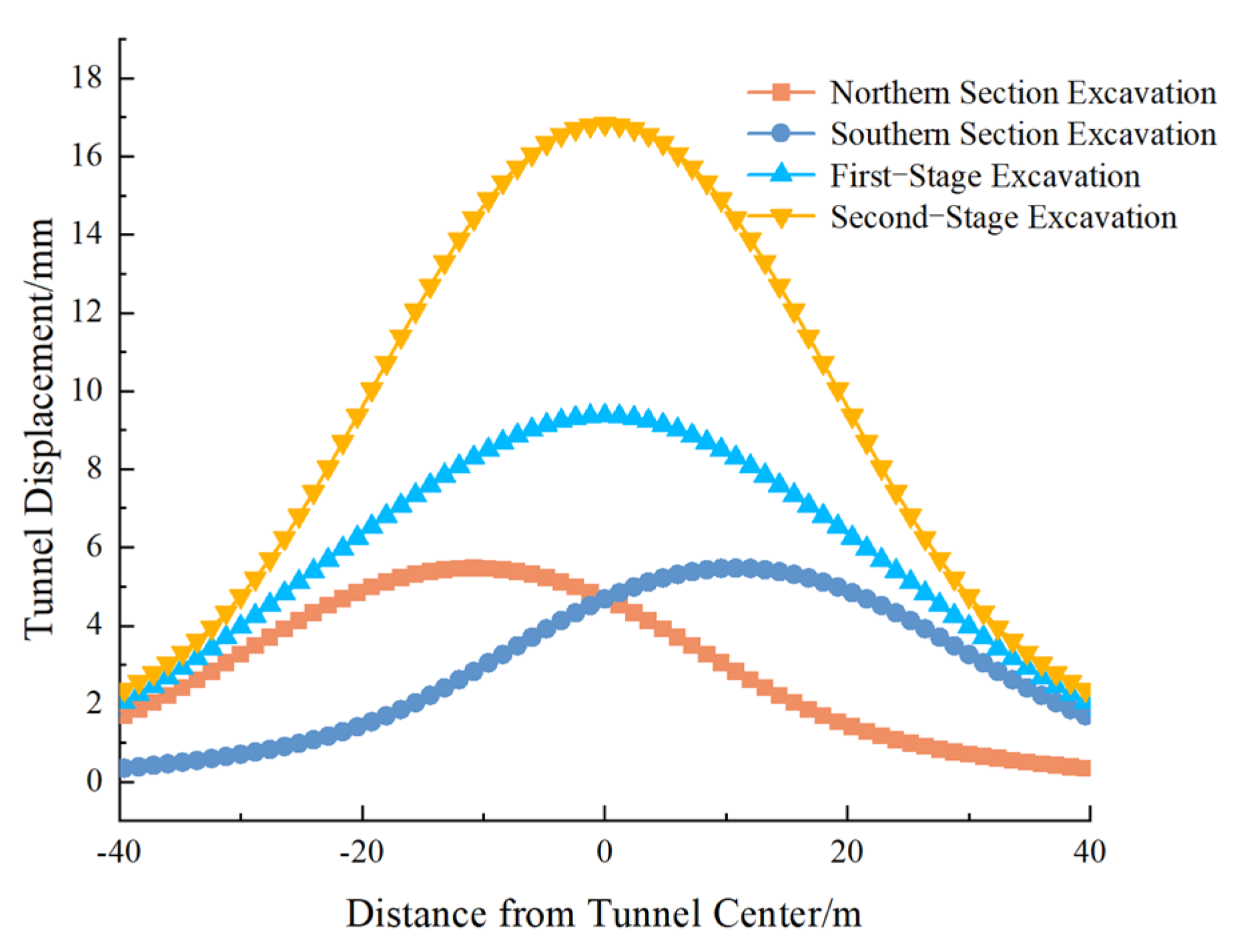
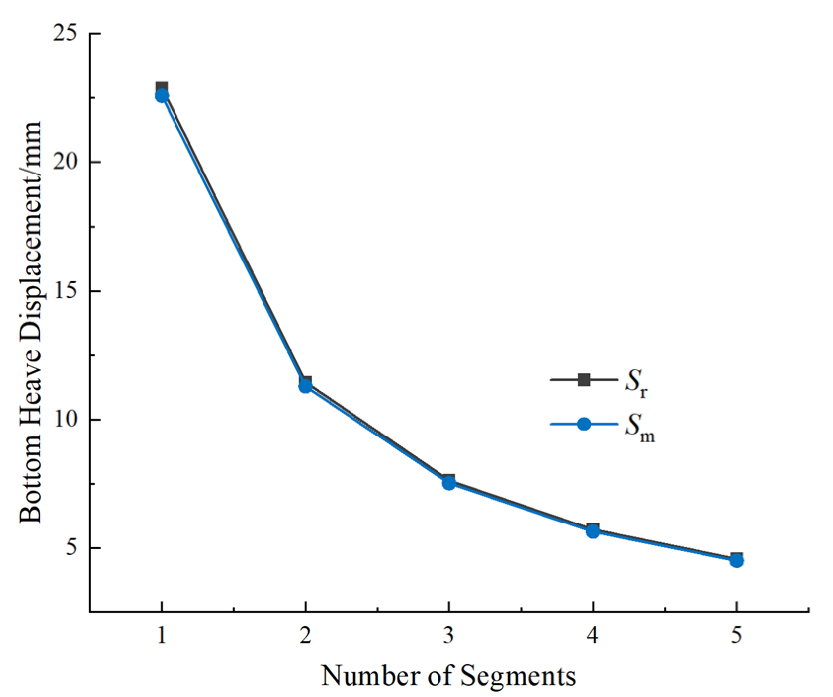
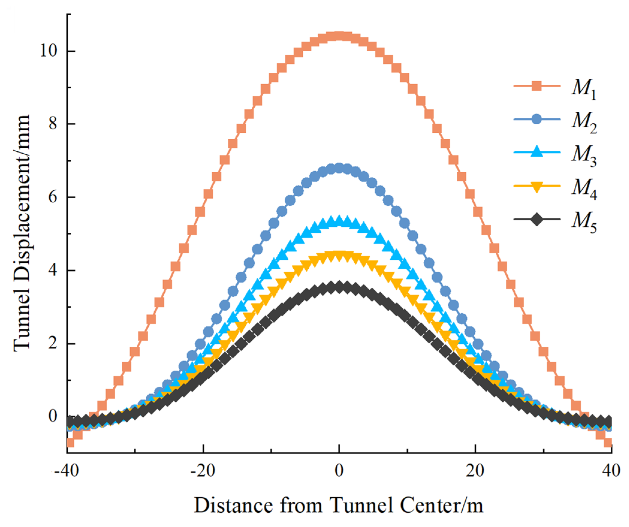
  • The excavation sequence significantly affects the magnitude and distribution of tunnel displacement. Single-step full excavation causes greater tunnel deformation, while staged and segmented excavation effectively reduces disturbance. The analysis demonstrates that increasing the number of excavation segments reduces both pit bottom heave and tunnel displacement.
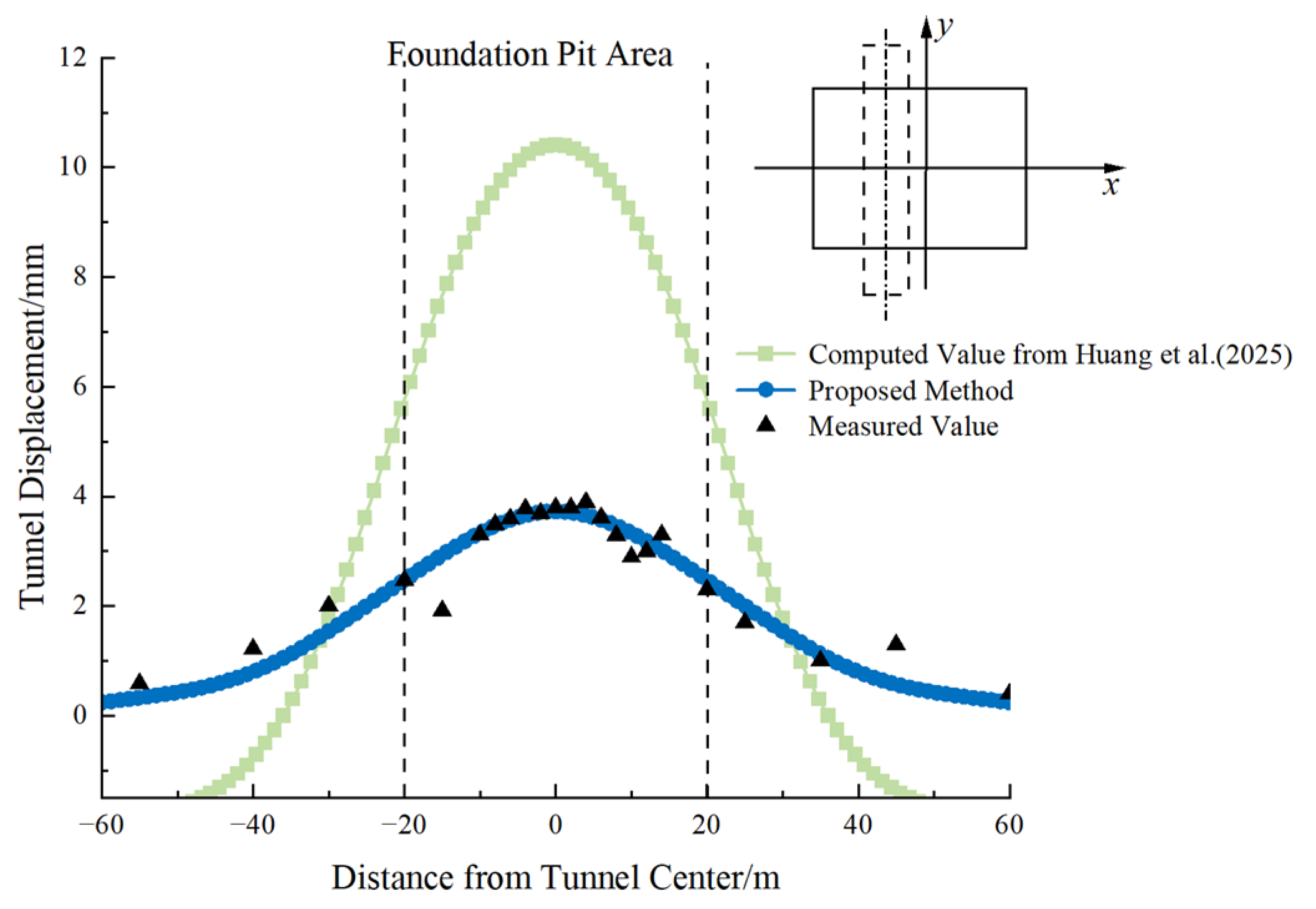
  • The proposed method provides a more accurate prediction of tunnel displacement compared to the two-dimensional image source method. The two-dimensional image source method overestimates tunnel deformation, especially when assuming single-step excavation. The results from the proposed method align closely with field measurements, verifying its accuracy.
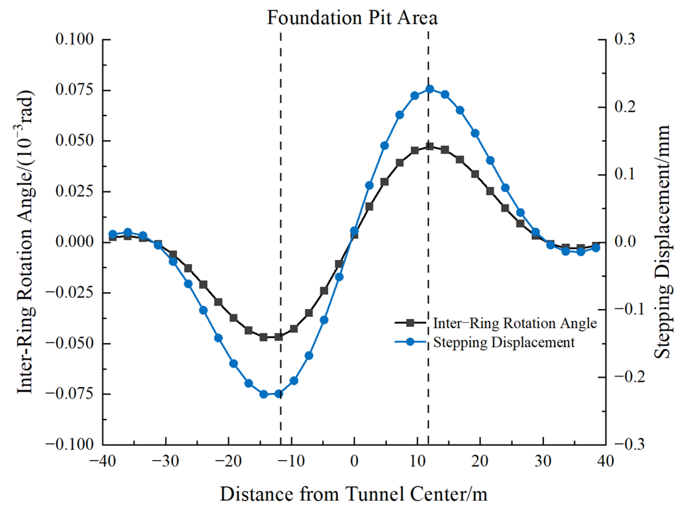
  • The rotational dislocation-coordinated deformation model successfully captures the stepping displacement and rotation angle between tunnel segments. The proposed method is applicable to complex excavation conditions, including non-orthogonal tunnel crossings and multi-stage excavation processes. The findings suggest that proper segmentation of excavation can effectively control tunnel displacement, enhancing excavation safety.
  • The proposed method demonstrates strong agreement with measured data in all three case studies. In Case 1, the predicted tunnel heave was 2.4 mm compared to the measured 2.3 mm, with a relative error of only 4.3%, whereas the Huang Maosong and Ni Yuping methods yielded errors exceeding 25%. In Case 2, the proposed method predicted a maximum deformation of 3.7 mm, significantly closer to field measurements than the 2D image source method, which overestimated deformation by 180%.
  • For excavation segmentation, increasing the number of excavation blocks from one to 16 reduced tunnel displacement by approximately 74%. However, further segmentation beyond 16 blocks resulted in marginal improvement (<5%) while increasing construction complexity. Therefore, the 9–16 block range is suggested as optimal for balancing deformation control and cost.
  • While the proposed model provides a practical and relatively accurate tool for predicting tunnel deformation induced by foundation pit excavation, it is subject to several limitations. The soil is assumed to be linearly elastic and horizontally layered, and the effects of nonlinear soil behavior, anisotropic stratification, and spatial variability are not considered. These simplifications may influence prediction accuracy, particularly in soft soils or heterogeneous formations. Future work may focus on extending the model to incorporate nonlinear constitutive laws, anisotropic soil parameters, and stochastic approaches that capture spatial heterogeneity. Additionally, hybrid frameworks combining analytical and numerical methods could enhance the applicability of the model in complex engineering conditions.
Overall, the proposed method provides a practical and accurate tool for predicting tunnel deformation under foundation pit excavation, offering valuable insights for design optimization and construction safety assessment in urban underground engineering.

Author Contributions

Methodology, G.W.; Validation, C.L.; Resources, Z.W.; Data curation, Q.W.; Writing—original draft, Y.Z.; Writing—review & editing, Y.Z.; Project administration, G.F. All authors have read and agreed to the published version of the manuscript.

Funding

This research was funded by National Natural Science Foundation of China grant number 52408448 and the APC was funded by National Natural Science Foundation of China.

Data Availability Statement

The original contributions presented in this study are included in the article. Further inquiries can be directed to the corresponding author.

Conflicts of Interest

The authors declare no conflict of interest.

References

  1. Zhuang, Y.; Cui, X.Y.; Hu, S.L. Numerical simulation and simplified analytical method to evaluate the displacement of adjacent tunnels caused by excavation. Tunn. Undergr. Space Technol. 2023, 132, 104879. [Google Scholar] [CrossRef]
  2. Shi, J.W.; Ng, C.W.W.; Chen, Y.H. Three-dimensional numerical parametric study of the influence of basement excavation on existing tunnel. Comput. Geotech. 2015, 63, 146–158. [Google Scholar] [CrossRef]
  3. Huang, H.; Shao, H.; Zhang, D.; Wang, F. Deformational responses of operated shield tunnel to extreme surcharge: A case study. Struct. Infrastruct. Eng. 2017, 13, 345–360. [Google Scholar] [CrossRef]
  4. Chang, C.-T.; Sun, C.-W.; Duann, S.; Hwang, R.N. Response of a Taipei Rapid Transit System (TRTS) tunnel to adjacent excavation. Tunn. Undergr. Space Technol. 2001, 16, 151–158. [Google Scholar] [CrossRef]
  5. Chen, R.P.; Meng, F.Y.; Li, Z.C.; Ye, Y.H.; Ye, J. Investigation of response of metro tunnels due to adjacent large excavation and protective measures in soft soils. Tunn. Undergr. Space Technol. 2016, 58, 224–235. [Google Scholar] [CrossRef]
  6. Hu, W.; Gu, X.W.; Liu, Y.; Shi, W.; Hu, Q.; Xu, X.B. Field study on the effect of excavation of strip-shaped foundation pit on existing underlying subway tunnels in soft soil. Build. Struct. 2023, 53, 2815–2822. [Google Scholar]
  7. Huang, M.S.; Li, H.; Yu, J.; Zhang, C.; Ni, Y. Approach for evaluating longitudinal deformation of underlying tunnels due to excavation of upper foundation pit. Chin. J. Geotech. Eng. 2023, 45, 2209–2216. [Google Scholar]
  8. Bi, S.Q.; Gan, B.L.; Liang, Y.H.; Yang, Y.H.; Li, H.; Cui, H.; Bian, C. Measurement and analysis of the influence of foundation pit excavation on existing short distance tunnel. Sci. Technol. Eng. 2022, 22, 1198–1204. [Google Scholar]
  9. Liang, R.Z.; Wu, J.; Sun, L.W.; Shen, W.; Wu, W. Performances of adjacent metro structures due to zoned excavation of a large-scale basement in soft ground. Tunn. Undergr. Space Technol. 2021, 117, 104123. [Google Scholar] [CrossRef]
  10. Meng, F.Y.; Hu, B.; Chen, R.P.; Cheng, H.; Wu, H. Characteristics of deformation and defect of shield tunnel in coastal structured soil in China. Undergr. Space 2025, 21, 131–148. [Google Scholar] [CrossRef]
  11. Doležalová, M. Tunnel complex unloaded by a deep excavation. Comput. Geotech. 2001, 28, 469–493. [Google Scholar] [CrossRef]
  12. Wei, G.; Feng, F.F.; Cui, Y.L.; Wang, X.; Diao, H.; Wu, Y. Research on the influence of foundation pit excavation on the lateral force and deformation of side shield tunnels based on full-scale experiments. Tunn. Undergr. Space Technol. 2023, 140, 105236. [Google Scholar] [CrossRef]
  13. Wei, G.; Feng, F.F.; Huang, S.Y.; Xu, T.; Zhu, J.; Wang, X.; Zhu, C. Full-scale loading test for shield tunnel segments: Load-bearing performance and failure patterns of lining structures. Undergr. Space 2025, 20, 197–217. [Google Scholar] [CrossRef]
  14. Lai, F.; Tschuchnigg, F.; Schweiger, H.F.; Liu, S.; Shiau, J.; Cai, G. A numerical study of deep excavations adjacent to existing tunnels: Integrating CPTU and SDMT to calibrate soil constitutive model. Can. Geotech. J. 2025, 62, 1–23. [Google Scholar] [CrossRef]
  15. Huang, X.; Huang, H.W.; Zhang, D.M. Centrifuge modelling of deep excavation over existing tunnels. Proc. Inst. Civ. Eng. Geotech. Eng. 2014, 167, 3–18. [Google Scholar] [CrossRef]
  16. Ng, C.W.W.; Shi, J.W.; Hong, Y. Three-dimensional centrifuge modelling of basement excavation effects on an existing tunnel in dry sand. Can. Geotech. J. 2013, 50, 874–888. [Google Scholar] [CrossRef]
  17. Gao, X.J.; Li, P.F.; Zhang, M.J.; Ge, Z.; Chen, C. Experimental investigation of ground collapse induced by Soil-Water leakage in local failed tunnels. Tunn. Undergr. Space Technol. 2025, 157, 105950. [Google Scholar] [CrossRef]
  18. Liu, J.W.; Shi, C.H.; Lei, M.F.; Cao, C. Improved analytical method for evaluating the responses of a shield tunnel to adjacent excavations and its application. Tunn. Undergr. Space Technol. 2020, 98, 103339. [Google Scholar] [CrossRef]
  19. Feng, G.H.; Chen, G.Z.; Zhang, D.; Sun, F.; Wang, P.; Li, Y.J.; Yang, Y.; Xu, C.J. Analytical solution on uplift deflection of underlying existing tunnel induced by foundation pit excavation. J. Railw. Sci. Eng. 2023, 20, 3908–3917. [Google Scholar]
  20. Zhang, J.F.; Chen, J.J.; Wang, J.H.; Zhu, Y.F. Prediction of Tunnel Displacement Induced by Adjacent Excavation in Soft Soil. Tunn. Undergr. Space Technol. 2013, 36, 24–33. [Google Scholar] [CrossRef]
  21. Cheng, K.; Xu, R.Q.; Ying, H.W.; Liang, R.; Lin, C.; Gan, X. Simplified method for evaluating deformation responses of existing tunnels due to overlying basement excavation. Chin. J. Rock Mech. Eng. 2013, 36, 24–33. [Google Scholar]
  22. Liang, R.Z.; Xia, T.D.; Huang, M.S.; Lin, C. Simplified analytical method for evaluating the effects of adjacent excavation on shield tunnel considering the shearing effect. Comput. Geotech. 2017, 81, 167–187. [Google Scholar] [CrossRef]
  23. Liu, J.W.; Shi, C.H.; Lei, M.F.; Peng, L.M.; Cao, C.Y. Analytical method for influence analysis of foundation pit excavation on underlying metro tunnel. J. Cent. South Univ. (Sci. Technol.) 2019, 50, 2215–2225. [Google Scholar]
  24. Guan, L.X.; Xu, C.J.; Wang, X.P.; Xia, X.Q. Analytical solution of deformation of underlying shield tunnel caused by foundation pit excavation and dewatering. Rock Soil Mech. 2023, 44, 3241–3251. [Google Scholar]
  25. Huang, M.F.; Zhong, Y.X.; Lu, J.B.; Wang, K.P. Deformation analysis of underlying shield tunnel induced by foundation pit excavation based on discontinuous foundation beam model. Rock Soil Mech. 2025, 46, 492–502. [Google Scholar]
  26. Liang, R.Z.; Xia, T.D.; Hong, Y.; Yu, F. Effects of Above-crossing Tunnelling on the Existing Shield Tunnels. Tunn. Undergr. Space Technol. 2016, 58, 159–176. [Google Scholar] [CrossRef]
  27. Feng, G.H.; Xu, C.J.; Ding, Z.; Tey, M.; Cao, Z.; Liang, L.; Fan, X.; Yang, K. Enhanced theoretical approach for predicting the tunnel response due to deep excavation above. Transp. Geotech. 2024, 48, 101309. [Google Scholar] [CrossRef]
  28. Sagaseta, C. Analysis of undrained soil deformation due to ground loss. Géotechnique 1987, 37, 301–320. [Google Scholar] [CrossRef]
  29. Xu, R.Q.; Cheng, K.; Ying, H.W.; Feng, S.Y.; Lin, C.G.; Yang, H.Y. Prediction of horizontal displacement of soils caused by excavation of foundation pits based on virtual mirror technology. Chin. J. Geotech. Eng. 2019, 41, 17–20. [Google Scholar]
  30. Yu, J.L.; Guo, J.; Zhou, J.J.; Gan, X.L.; Gong, X.N.; Xiao, F.Q. Analysis of lateral deformation of adjacent pile induced by braced excavation considering spatial effect in ground of homogeneous soil. Chin. Civ. Eng. J. 2023, 56, 140–152. [Google Scholar]
  31. Wei, G.; Guo, B.L.; Wang, Z.; Liu, J. Deformation calculation of underlying shield tunnel caused by unloading of foundation pit considering excavation width. Chin. J. Rock Mech. Eng. 2023, 42, 1019–1030. [Google Scholar]
  32. Li, D.N.; Lou, X.M.; Yang, M. Research and application of calculation methods for rebound deformation of foundation pits. Chin. J. Rock Mech. Eng. 2012, 31, 1921–1927. [Google Scholar]
  33. Zai, J.M. Simplified method for prediction of excavation rebound. J. Nanjing Archit. Civ. Eng. Inst. 1997, 41, 25–29. [Google Scholar]
  34. Zhang, H.Y. Study on Deformation Law and Basal Heave Stability of Inclined Hard Layer Foundation Pit Under Soft Soil. Master’s Thesis, East China University of Technology, Shanghai, China, 2023. [Google Scholar]
  35. Feng, H. Research on Three-Dimensional Analysis Method for Stability of Ultra-Deep Foundation Pit Against Uplift. Master’s Thesis, Zhengzhou University, Zhengzhou, China, 2013. [Google Scholar]
  36. Wei, G.; Zhang, X.H. Calculation of rotation and shearing dislocation deformation of underlying shield tunnels due to foundation pit excavation. J. Cent. South Univ. 2019, 50, 2273–2284. [Google Scholar]
  37. Guo, L.; Yang, X.A.; Qiu, Y. Longitudinal heterogeneous equivalent continuous model for stagger joint segmental lining. Urban Mass Transit 2017, 20, 17–22. [Google Scholar]
  38. Vesic, A.B. Bending of beams resting on isotropic elastic solids. J. Eng. Mech. 1961, 87, 35–53. [Google Scholar]
  39. Ni, Y.P. Simulation of Tunnel Deformations Adjacent to Excavation Based on a Small Strain Non-Linear Hypoelastic Model. Master’s Thesis, Tongji University, Shanghai, China, 2019. [Google Scholar]
  40. Zhang, Z.G.; Zhang, M.X.; Wang, W.D. Two-stage method for analyzing effects on adjacent metro tunnels due to foundation pit excavation. Rock Soil Mech. 2011, 32, 2085–2092. [Google Scholar]
  41. Ren, S.P.; Chen, X.J.; Ren, Z.L.; Cheng, P.; Liu, Y. Large-deformation modelling of earthquake-triggered landslides considering non-uniform soils with a stratigraphic dip. Comput. Geotech. 2023, 159, 105492. [Google Scholar] [CrossRef]
Figure 1. Two-dimensional “single-peak” heave shape.
Buildings 15 02046 g001
Figure 2. Relative position diagram of foundation pit and tunnel.
Buildings 15 02046 g002
Figure 3. Relative relationship between the assumed semi-circular shape and the actual excavation surface.
Buildings 15 02046 g003
Figure 4. Top view of foundation pit bottom heave.
Buildings 15 02046 g004
Figure 5. Computational model of the image source method.
Buildings 15 02046 g005
Figure 6. Schematic diagram of the mirroring process in the image source method.
Buildings 15 02046 g006
Figure 7. Relative position diagram of the tunnel axis and coordinate system.
Buildings 15 02046 g007
Figure 8. Computational model of shear stepping and rotational coordinated deformation.
Buildings 15 02046 g008
Figure 9. Relative position map of foundation pit and tunnel (Unit: m).
Buildings 15 02046 g009
Figure 10. Comparison of longitudinal deformation calculations for the underlying tunnel in Case 1: proposed method vs. measured data and existing methods. The proposed method yields a high degree of agreement with field data (R2 = 0.982) [7,32].
Buildings 15 02046 g010
Figure 11. Segmental ring stepping displacement and rotation angle.
Buildings 15 02046 g011
Figure 12. Inter-Ring shear force of tunnel segments.
Buildings 15 02046 g012
Figure 13. Comparison of longitudinal deformation calculations for the tunnel in Case 2 [25].
Buildings 15 02046 g013
Figure 14. Foundation pit excavation sequence diagram (Unit: mm).
Buildings 15 02046 g014
Figure 15. Comparison of longitudinal tunnel deformation calculations at different excavation stages.
Buildings 15 02046 g015
Figure 16. Comparison of longitudinal tunnel deformation calculations [25].
Buildings 15 02046 g016
Figure 17. Schematic diagram of the impact of segmented excavation on pit bottom heave.
Buildings 15 02046 g017
Figure 18. Schematic diagram of the influence of a different number of sections on the uplift at the bottom of the pit.
Buildings 15 02046 g018
Figure 19. Schematic diagram of the influence of a different number of sections on the displacement of the tunnel.
Buildings 15 02046 g019
Table 1. Table of soil layer parameters for Case 1.
Soil Layer NumberSoil Layer NameLayer
Thickness/m
Unit Weight/kN·m−3Cohesion/kPaInternal Friction Angle/°Compression
Modulus/MPa
Plain Fill Soil1.55-4.08.05.0
②-1Silty Clay1.1318.410286.43
②-2Silty Clay0.8217.713223.71
③-1Muddy Clay1.0817.71421.54.43
③-2Sandy Silt with Interbedded Silty Clay2.2818.3334.59.72
③-3Muddy Silty Clay2.4617.213203.63
Muddy Clay8.7016.61492.27
Clay2.4117.91913.54.07
Table 2. Table of soil layer parameters for Case 2.
Soil Layer NumberSoil Layer NameNatural Water ContentCompression Modulus/MPaCohesion/kPaInternal Friction Angle/°Unit Weight
Plain Fill Soil-5.04.08.03.0
Silty Clay30.35.4722.214.33.4
Interbedded Silty Clay and Silt30.96.4620.115.54.3
Muddy Clay43.73.2415.19.95.9
⑤-1Silty Clay26.37.441.914.98.0
⑤-2Silty Clay24.938.816.213.23.6
Gravel-351386.7
Disclaimer/Publisher’s Note: The statements, opinions and data contained in all publications are solely those of the individual author(s) and contributor(s) and not of MDPI and/or the editor(s). MDPI and/or the editor(s) disclaim responsibility for any injury to people or property resulting from any ideas, methods, instructions or products referred to in the content.

