Article

Analysis of Structural Internal Forces and Stratum Deformation in Shaft Construction Using Vertical Shaft Sinking Machine

1
Department of Civil Engineering, University of Science and Technology Beijing, Beijing 100083, China
2
Shanghai Tunnel Engineering & Rail Transit Design and Research Institute, Shanghai 200235, China
*
Author to whom correspondence should be addressed.
Buildings 2025, 15(12), 2043; https://doi.org/10.3390/buildings15122043
Submission received: 12 May 2025 / Revised: 6 June 2025 / Accepted: 11 June 2025 / Published: 13 June 2025
(This article belongs to the Section Building Structures)

Abstract

The use of the vertical shaft sinking machine (VSM) for shaft construction can effectively improve construction safety and efficiency. This study focused on analyzing the internal forces and deformation characteristics of a 50.3 m deep shaft constructed by the VSM method. Findings reveal that the external pressure of the shaft is positively correlated with the excavation depth, increasing as the depth grows. Pumping water inside the shaft disrupts the balance of the soil behind it, leading to a reduction in the external pressure of the shaft wall. During the excavation and sinking stage, the bottom connecting beam mainly endures compression. After water pumping, the coupling and restrictive effect between the bottom connecting beam and the shaft wall strengthens, significantly boosting the internal compressive stress. The stress states of the segments above and below the shaft vary: the upper segments are under pure compression, while the lower ones may experience uneven deformation due to multiple factors. Moreover, the cast-in-place piles and surrounding stratum show a “bulging” deformation pattern during sinking, greatly influenced by the shaft’s attitude deviation, whereas grouting at the shaft bottom and internal water pumping have minimal impact on the surrounding stratum.

1. Introduction

With the continuous development of urban construction, the excavation of underground space is trending towards greater complexity and diversification. As a typical underground building, the shaft has a simple structural construction and a uniform load distribution, and it often plays an important role in mining and tunnel construction [1,2].
The development of vertical shafts in engineering construction is a history of continuous breakthroughs and innovations. Initially, vertical shafts adopted cast-in-place shaft wall structures. Traditional mechanical equipment such as excavators were used for excavation and slag removal, and the shafts sank by relying on their own weight to overcome the friction with the soil layer [3]. However, this method has low construction efficiency, poor stability, and is prone to sudden sinking or the stoppage of sinking. It also has a significant impact on the surrounding environment. With the evolution of technology, new methods such as the space system (SS) [4] caisson method, the press-in caisson method [5], and the super open caisson system (SOCS) method [6] have emerged. In the SS method [4], the outer contour of the cutting edge extends approximately 15–20 cm beyond the boundary of the shaft wall, creating a gap between the outer wall of the shaft and the soil. Gravel is filled in the gap to reduce frictional resistance while ensuring the stability of the ground. The press-in caisson method [5] uses a ground anchor reaction device and a through-hole jack at the top of the shaft on the ground to apply downward pressure, solving the problem of difficult sinking and enabling the adjustment of the shaft’s attitude. It is suitable for projects with strict environmental requirements. Based on the press-in method, the SOCS method [7] uses an underwater excavator on the inner wall of the shaft to dig the soil and discharge the sludge, reducing the sinking resistance, and then presses the shaft into the ground with the ground anchor reaction device. It is suitable for urban construction projects. The vertical shaft sinking machine [8,9,10,11] developed by Herrenknecht AG in Germany is more advanced. It uses underwater excavation to improve excavation efficiency. The VSM method reduces resistance through over-excavation and filling with bentonite slurry. The movement is controlled by a lowering unit to avoid sudden sinking. It also integrates the shield tunnel lining technology and can precisely and actively control the sinking process. It has many advantages such as deep excavation, little disturbance, and high speed, and is widely used in practical projects with good results [12,13,14]. Some projects with shaft construction using the VSM method are shown in Table 1. However, it should be noted that there are still many difficulties and limitations in the shaft sinking by the VSM method. For example, due to the prefabricated structure of the shaft wall, the shape of the shaft is mostly limited to a circular shape. Also, the shaft is excavated blindly underwater during the sinking process, and encountering obstacles such as gravel during the excavation may damage equipment and cause construction delays. In addition, the underwater concrete pouring after the excavation is completed also poses great challenges to on-site construction.
Regarding the shaft using the VSM method, which is a new type of excavation method, many scholars have carried out relevant research on the disturbance deformation caused by its construction. Huang [15] analyzed the change trends of internal forces and the corresponding structural laws of a VSM shaft wall during the construction process in Nanjing through on-site monitoring. By constructing a numerical simulation model, Ma [16] discussed in detail the displacement and stress changes of the surrounding strata during the sinking process of the VSM shaft, as well as the relationship between these changes and the shaft construction parameters, providing an important theoretical basis for understanding the impact of the VSM construction method on the strata. Subsequently, scholars such as Liu [17] further expanded the research in this field. Using the numerical simulation method as well, they deeply analyzed the structural deformation characteristics of VSM—constructed shafts under different reinforcement depths and cast-in-place pile diameters. Lu [18] analyzed the ground deformation patterns during VSM construction in soft soil areas by establishing a numerical model and recommended the vertical deformation zones should be classified into a groove-shaped settlement zone, heave influence zone, and heave zone on the basis of the deformation of the soil outside the shaft after the completion of sinking. Abualghethe [19] simulated the construction process of the vertical support system (VSM) through comprehensive numerical analysis, analyzed the deformation of the shaft structure, surrounding soil, and adjacent buildings, evaluated the influence of different reinforced ring foundation depths, and finally provided the optimal reinforced ring depth in this case. Although the above-mentioned research has made some progress, most of these studies are limited to the shaft sinking stage, and there is a lack of research during the bottom concrete pouring and water pumping stage. It should also be noted that most of these results were obtained through numerical simulation methods. Although numerical simulation can reflect the mechanical behavior and deformation characteristics of structures to a certain extent, there are still certain differences from the actual construction process.
Although there are currently few practical measurements and analyses of the deformation during the construction of shafts by the VSM method, some studies on the stress characteristics [20,21,22,23,24,25,26] and deformation patterns [27,28,29,30,31,32] of circular deep foundation pits and traditional shaft structures can provide references. The research on the stress characteristics of the shaft mainly focuses on the analysis of the external pressure [22,26] distribution of the shaft wall, the analysis of the frictional resistance [20] of the sidewall during the shaft sinking process, the study of the bearing capacity of the shaft cutting edge [21,23,25], and the characteristics of the load distribution [24] of the shaft structure. The research on deformation patterns mainly focuses on aspects such as the deformation of the stratum and the deflection of the wall. For example, Qiao [27] analyzed the excavation data of 30 circular shafts and found that the maximum wall displacement of ultra-deep shafts usually ranges from 0.06% to 0.30% of the excavation depth and the wall displacement is also related to the diameter of the shaft. Kim [28] found that the nonlinearity of the soil in coastal areas has a significant impact on the lateral wall displacement, and the elastic modulus of the soil decreases significantly after excavation by analyzing the lateral wall displacement caused by the excavation of a 75 m deep circular foundation pit in a coastal area through on-site monitoring. Wang [29] studied the relationship between the structural displacement of a circular foundation pit in Shanghai and the excavation depth and proposed a new formula for estimating ground settlement. Jia [30] analyzed the structural deformation characteristics of a circular foundation pit in Shanghai, discussed the distribution and development of the total lateral pressure, and proposed the relationship between the normalized wall deformation and the stiffness of the ring beam. The shaft constructed by the VSM has significant differences from other types of circular vertical shafts. The distribution of structural loads for it is more complex, and the stratum deformation caused by the VSM excavation is more unique. Therefore, it is necessary to study the internal force changes of the VSM shaft wall structure and the deformation of the surrounding strata.
Based on this, this paper selects a shaft using VSM in Shanghai as the research object, and takes on-site monitoring as the main research method, focusing on the internal forces of the shaft wall and the bottom beam, and the deformation of the surrounding strata and piles. During the research process, from the perspectives of the two key construction stages of shaft sinking and subsequent bottoming concrete pouring and water pumping, the internal forces and deformation characteristics of the VSM method are systematically analyzed. This study provides strong practical evidence and theoretical support for the widespread application and optimized design of the VSM method in future engineering projects.

2. Project Overview

In the underground garage project in Shanghai, the VSM technology was employed for shaft excavation. This project entailed the construction of two ultra-deep shafts. Being the shafts with the largest diameter excavated by the VSM mechanical method globally at present, they have a diameter of 23.02 m. The final excavation depth is approximately 50.5 m, and the depth of the bottom slab is set at 44 m.

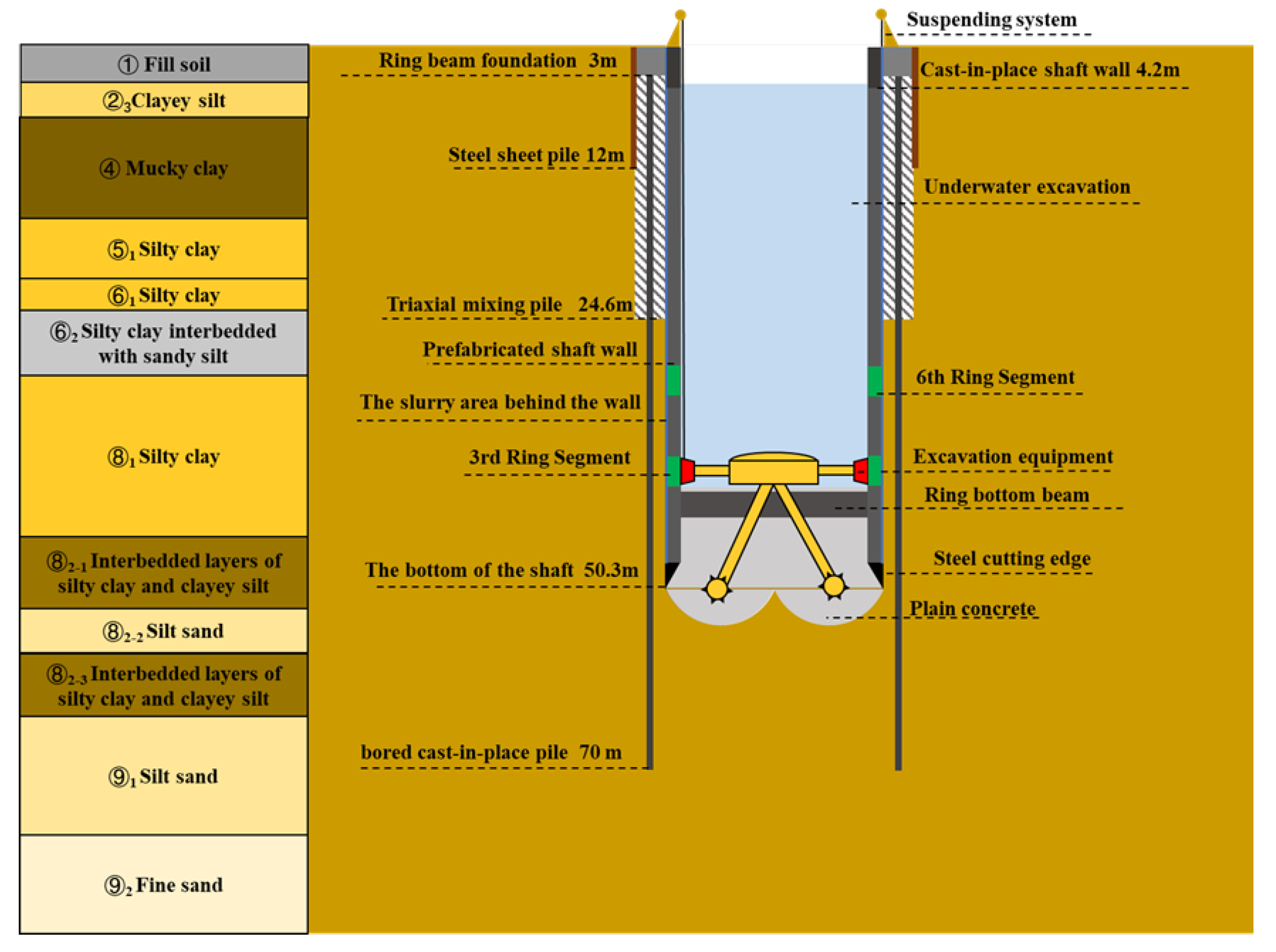
2.1. Geotechnical Conditions

This site is located in the Yangtze River Estuary area. The underground soil structure here shows specific distribution characteristics, mainly consisting of soft clay layers. Beneath the soft clay layers, there is a certain range of sandy soil layers. Except for the surface miscellaneous fill soil, the distribution of soil layers within a depth of 90 m underground in this area and their main basic physical parameters and mechanical parameters are detailed in Figure 1. As can be seen from the figure, within the 0–50 m excavation range, the physical and mechanical properties of the strata are heterogeneous, among which the physical and mechanical properties of the mucky clay layer are significantly different from those of other strata; the 50–90 m range is mainly dominated by sandy soil, with relatively small variations in its physical and mechanical properties.
The groundwater in the site is mainly phreatic water, which is stored in shallow soil layers. The depth of the phreatic water surface from the ground surface usually ranges from 0.3 to 1.5 m. It is worth noting that there are confined water layers distributed in the ⑧2–2 silty sand layer and the ⑨1 silty sand layer.

2.2. Vertical Shaft Sinking Method

The main structures of the shaft constructed by the VSM excavation method include excavation equipment, the suspending system, prefabricated concrete segments, the steel cutting edge, and the slurry treatment system. In this case, there are a total of 23 rings of concrete segments, with each ring being 2 m high. Each ring is arranged with 10 segments, which are divided into two types, A and B. Type A is a trapezoid with a shorter bottom edge and a longer upper edge, and type B is a trapezoid with a shorter upper edge and a longer bottom edge. The segments are connected by bolts.
In the early stage of the shaft construction, a foundation pit larger than the diameter of the shaft needs to be excavated in advance as the launching foundation pit. Subsequently, cast-in-place bored piles and three-axis mixing piles are constructed within the launching foundation pit, and a top ring beam is built in the foundation pit to serve as the bearing platform of the suspending system. At the same time, the steel cutting edge at the bottom of the shaft and the segments of the first, second, and third rings are assembled within the foundation pit. Since the diameter of the shaft in this case is relatively large and the buried depth is relatively deep, a bottom support beam also needs to be designed at the bottom of the shaft to reduce the deformation of the shaft. The support beam includes the bottom connecting beam, the bottom ring beam, and the surrounding side walls, and its structure is shown in Figure 2.
When the supporting structure of the shaft meets the strength requirements, the excavation equipment is installed and the excavation of the shaft begins. During the excavation, the size of the steel cutting edge of the shaft is slightly larger than that of the segments, so there is a gap of approximately 10 cm between the outer wall of the shaft and the soil layer. During the construction, bentonite slurry needs to be filled in this gap to reduce the frictional resistance on the side wall of the shaft.
After the shaft is excavated to the specified height, plain concrete is used to replace the slurry behind the shaft wall. Subsequently, the excavation equipment is removed, and the underwater bottom plain concrete pouring operation is carried out, with the bottom pouring height set at 6.6 m. Finally, the water inside the shaft is pumped out, and at this point, the construction of the shaft structure is completed. The entire structure of the shaft is shown in Figure 3.
In this case, the shaft excavation started on 26 January 2024, and the pumping was completed on 23 May. The excavation and sinking stage occurred from 26 January to 21 April. The excavation speed during the tunneling stage is shown in Figure 4. The subsequent concrete pouring and pumping stage occurred from 21 April to 23 May. For convenience, in this paper, the shaft excavation and sinking stage is defined as stage 1, and the subsequent slurry replacement, bottom concrete pouring, and pumping inside the shaft are defined as stage 2. The construction processes of the shaft excavation are summarized in Table 2.

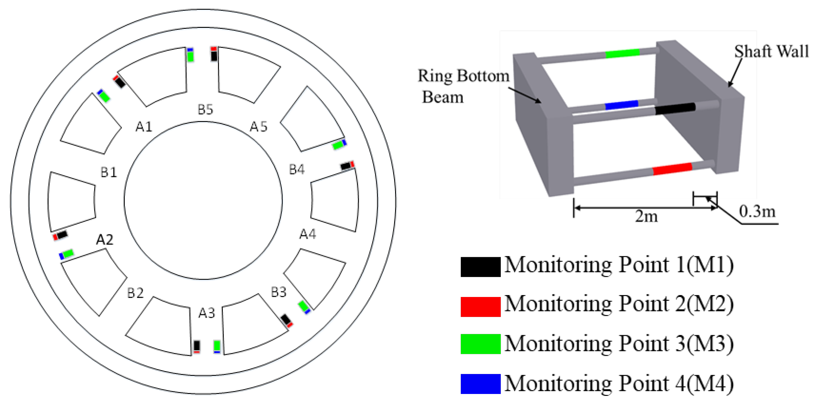
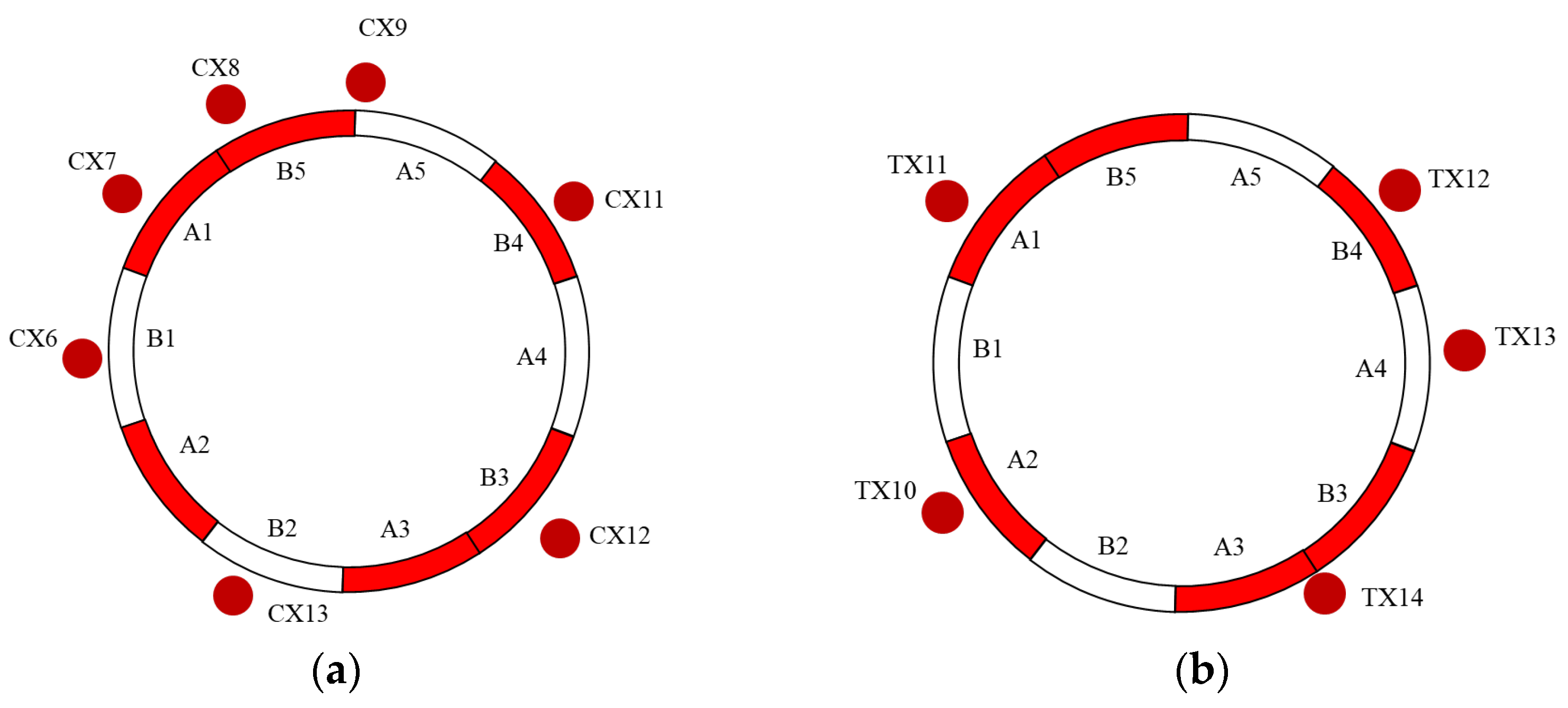
2.3. Monitoring Programs and Date Acquisition

Based on the structural characteristics and construction features of the shaft using the VSM method, a corresponding monitoring plan has been formulated for each construction link of the shaft.
(1) Monitoring of segments
Measuring points are, respectively, set on the segments numbered A1, A2, A3, B3, B4, and B5 in the third and sixth layers of the shaft. For each segment, measuring points for the internal force are arranged on the circumferential steel bars of the inner and outer arc surfaces near its two sides. Meanwhile, external pressure measuring points are arranged at the center of the segment. Each segment has a total of four measuring points for the axial force of the steel bars and one measuring point for the external pressure. In order to distinguish the positions and names of the four internal force monitoring points, the four monitoring points are respectively numbered as M1, M2, M3, and M4, and the specific monitoring points and their distributions are shown in Figure 5.
(2) Monitoring of bottom connecting beam
Monitoring points are, respectively, set on the connecting beams numbered A1, A2, A3, B3, B4, and B5. For each bottom connecting beam, four measuring points for the axial force of the steel bars are arranged on the outermost main bars near the position of the shaft segments, with two axial force measuring points arranged at the upper and lower parts, respectively. Similar to the measuring points of the segments, Figure 6 also shows the specific positions and numbers of the monitoring points of the bottom connecting beams.
(3) Monitoring of the Deformation of the Surrounding Structures
In addition to the monitoring of the internal forces of the shaft wall structure, this article also focuses on the monitoring of the horizontal deformation of the piles of the shaft and the stratum around the shaft, so as to analyze the influence of the shaft construction process on the disturbance of the surrounding stratum. Figure 7 shows the monitoring points for the horizontal movement of the piles around the shaft and the stratum.
The monitoring points and their numbers are shown in Table 3. In the data collection and analysis phase, the internal forces of segment and connecting beams were monitored using vibrating wire sensors, with data captured by an automated data acquisition system at a sampling interval of once every 4 h. The steel bar axial force sensor can withstand a maximum axial force of 123 kN, while the external pressure sensor can withstand a maximum pressure of 1.6 MPa. The deformation of surrounding strata and piles was monitored by manual measurement with a sampling frequency of once per day. The automated data acquisition equipment was powered by solar energy to ensure long-term stable operation. During data acquisition, the automated equipment first obtained the current frequency f i of the sensor, and the current internal force of the sensor was calculated through Equation (1):
F = k ( f i 2 f 0 2 )
where F is the internal force of the sensor, f i is the current frequency of the sensor, f 0 is the frequency of the sensor measured after installation, and k is the calibration coefficient of the sensor.

3. Monitoring Analysis of Structural Internal Force

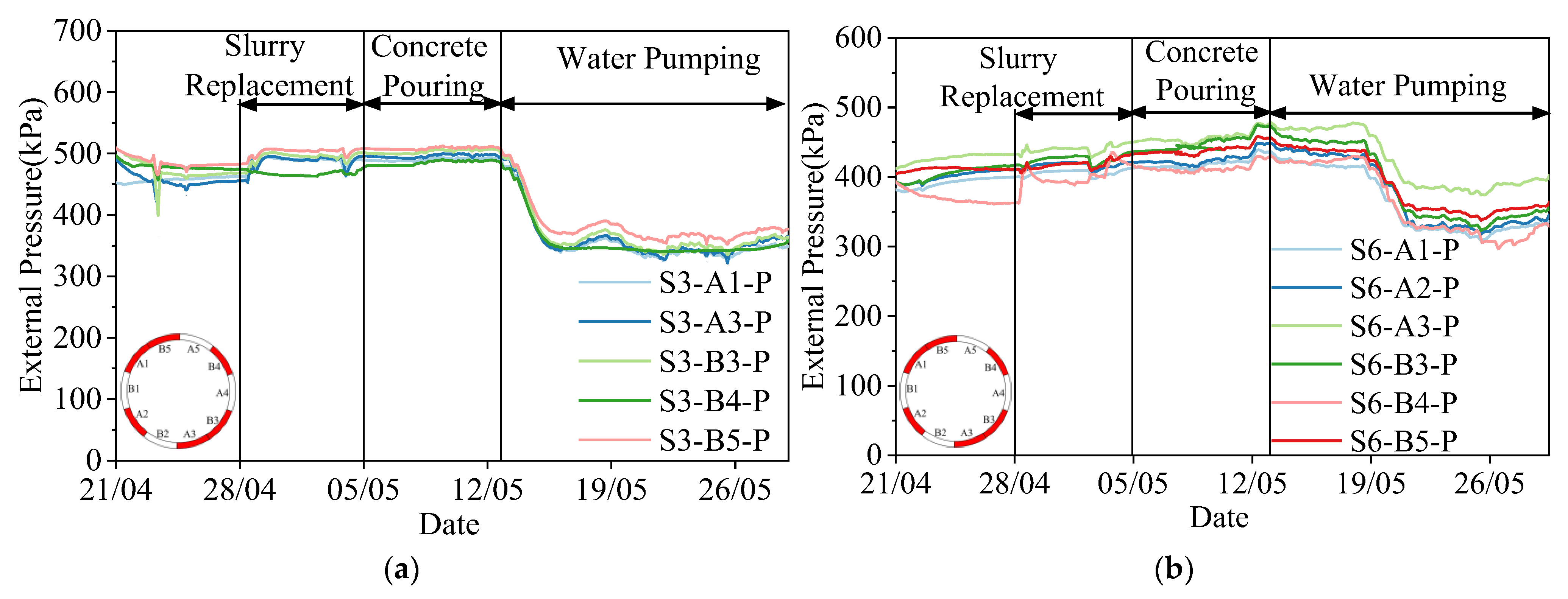
3.1. Analysis of External Pressure on Shaft Segment

Figure 8 presents the evolutions of external pressures acting on the outer surfaces of the third and sixth segmental rings during stage 1. At the beginning of stage 1, the pressures on the third and sixth rings are close to zero because only the cutting edge and the first ring segments are embedded in the stratum. As excavation advanced to depths of approximately 11 m and 19 m, the external pressures on the third and sixth rings begin to increase gradually, indicating that these segments gradually enter the main bearing zone. As the excavation continued, the interaction between the shaft structure and the surrounding soil intensified, leading to a synchronous increase in external pressure recorded at all monitoring points. When excavation reaches the design’s bottom depth, the external wall pressures on the third and sixth rings reach approximately 450 kPa and 350 kPa, respectively, showing an obvious depth correlation. Classical earth pressure theories [33,34] suggest that the pressure on retaining walls is significantly influenced by the physical and mechanical parameters of soil, especially the lateral earth pressure coefficient. However, it is noted that during the sinking process of the shaft, the external pressure does not have a direct correlation with the soil physical and mechanical parameters shown in Figure 1. This is because the slurry filling on the outer shaft wall complicates the actual soil composition acting on the shaft wall, resulting in smaller differences in external pressure exerted by soil layers with different mechanical properties on the shaft wall.
In addition, by comparing the external wall pressures of different segments at the same depth, small pressure differences can be observed. This indicates that the soil conditions at this depth are relatively uniform, and the soil–structure interaction remains stable. These results indirectly confirm the equalization and distribution regularity of the force on the segmental lining during the shaft excavation process in this project.
Figure 9 illustrates the evolution of earth pressure acting on the extrados of segment rings S3 and S6 during stage 2. During the slurry replacement process at the external wall of the shaft, although a slight increase in earth pressure is observed, the overall variation remains relatively slight and significantly lower than the typical characteristics of the drastic change in soil pressure before and after post-wall grouting in conventional shield construction [35]. This discrepancy can be attributed to the fact that, during shaft sinking, the annular gap around the external wall is naturally filled and compacted by the surrounding soil, forming a stable support. As a result, the slurry replacement does not substantially disturb the existing soil–structure mechanical equilibrium, thereby limiting the magnitude of pressure variation.
Following the commencement of the water pumping phase (after 12 May), the earth pressure on the outer wall continued to decrease and eventually stabilized as the water was gradually removed from the shaft. This phenomenon can be attributed to the rapid release of internal hydrostatic pressure as the water inside the shaft is pumped out, which induces a slight inward contraction of the segmental lining. Consequently, the counteracting force exerted on the surrounding soil is reduced, and the external wall stress state gradually approaches the active earth pressure limit equilibrium. This transition ultimately leads to an overall decrease in earth pressure acting on the shaft lining.

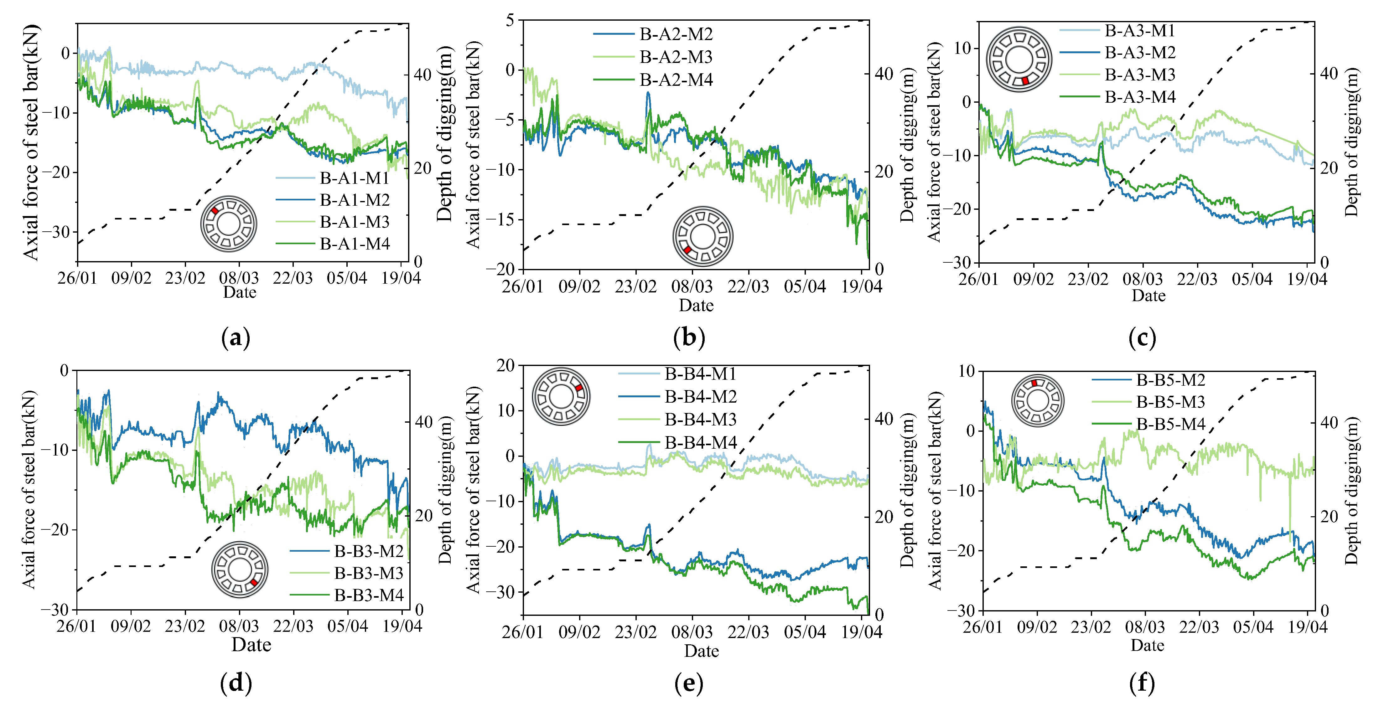
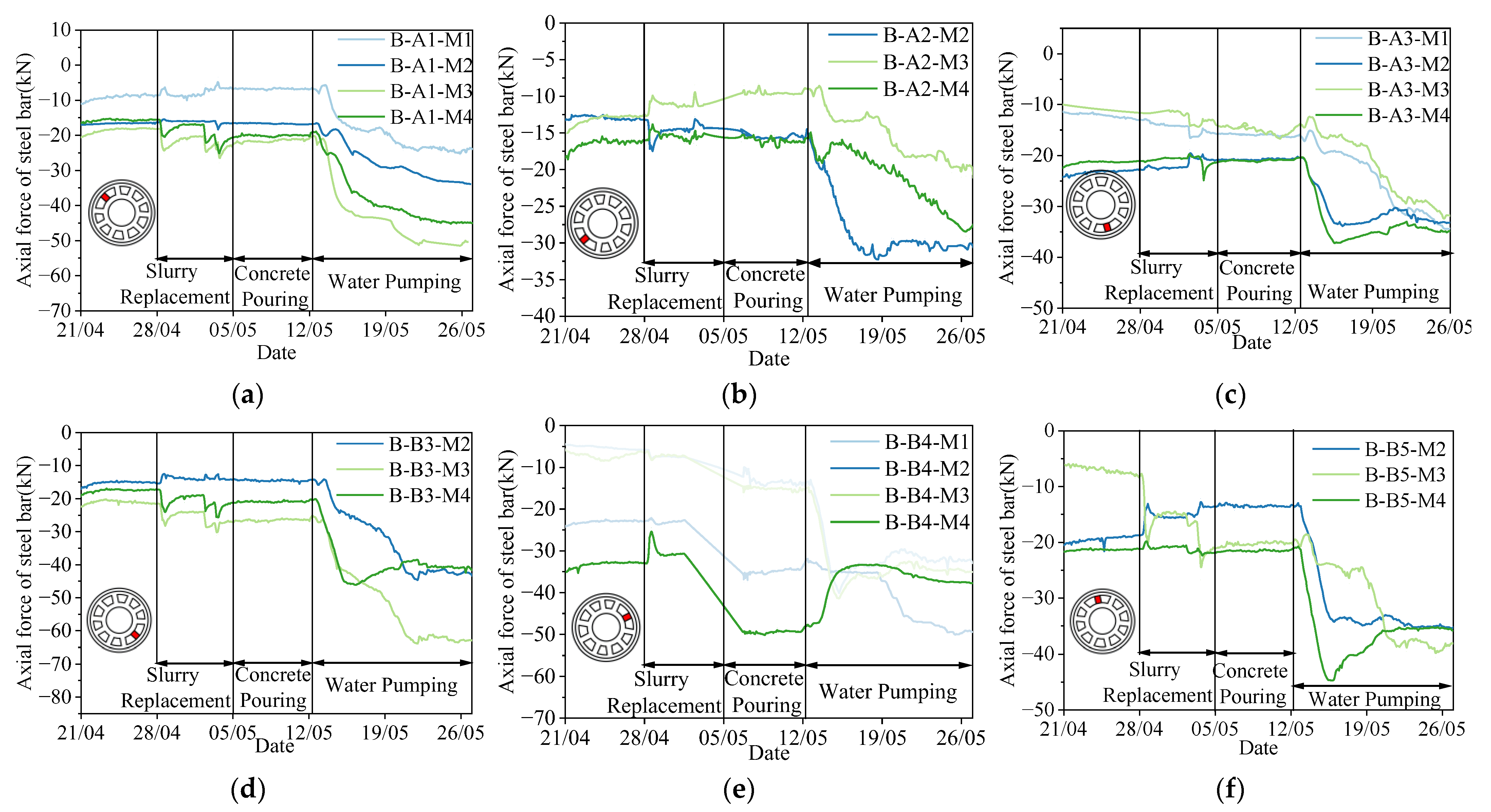
3.2. Axial Force of Steel Bars in the Bottom Connecting Beam

The time–history variations in the axial force of steel bars in the bottom connecting beam during stage 1 are shown in Figure 10. Note that the compression axial force of steel bars is defined as negative, and the tension is defined as positive in this study. The monitoring results show that the axial force of steel bars at each measurement point is always negative, suggesting that the bottom connecting beam is in a significant state of compression in the excavation process. At the initial excavation stage, one can observe the significant fluctuation in the axial force of each beam, which gradually stabilized during the excavation pause. As the shaft continued to sink, the trend of the reinforcement axial force of different beams diverges. The change in the measurement point M1 is small, while M2 and M4 show a continuous increase. In addition, the measurement point M3 demonstrates localized variations, particularly with a steady increase in axial force observed in beams A1 and A2, whereas other locations showed minimal change.
It should be noted that the loads acting on the bottom connecting beam mainly consist of three components: (i) the self-weight of the structure generating permanent load; (ii) the buoyancy effect arising during underwater excavation; and (iii) the lateral earth pressure exerted by the surrounding soil mass. The latter is transferred through the shaft lining and the central bottom ring beam to the bottom connecting beam, constituting the primary source of loading. As observed in Figure 10, compressive forces in the lower reinforcement (M2, M4) are significantly greater than those in the upper reinforcement, indicating that the connecting beam is predominantly subjected to vertical bending. This bending effect results from the initial downward deflection of the connecting beam under self-weight, which is further intensified by the progressive increase in lateral earth pressure.
Furthermore, although some monitoring points recorded a slight increase in axial force during excavation, the overall variation remained limited, suggesting that the internal forces in the bottom connecting beam are relatively insensitive to disturbances caused by shaft excavation. This can be attributed to the presence of internal water pressure within the shaft, which partially counteracts the external earth pressure, thereby mitigating the structural stress fluctuations experienced by the bottom connecting beam.
Figure 11 illustrates the evolution of axial forces of steel bars at various positions along the bottom connecting beam during stage 2. Considering the deviation of sensor installation accuracy and the potential human-induced disturbances during construction, it is reasonable that there are some differences between the internal force curves of reinforcement bars at different locations. As observed in Figure 11, the slurry replacement stage behind the shaft wall exerted a relatively limited influence on the internal forces of the connecting beam reinforcement. The axial forces at all monitoring points show minor fluctuations, indicating that the external earth pressure and internal hydraulic support remained in a relatively balanced state during this period, and the structural response is stable. In contrast, the water pumping stage had a more pronounced impact on internal forces. It can be observed that the axial force of reinforcement at each monitoring point of beams A1, A2, A3, and B4 generally showed a rapid increase and then stabilized. However, it is worth noting that the axial force of measurement point M4 of beam B4 showed a significant decrease in the change pattern. This localized variation suggests that under the rigid constraint of the internal bottom ring beam, the stress distribution within the bottom connecting beam was spatially non-uniform, with evident three-dimensional structural effects and zone-specific responses.
In addition, the bottom connecting beam entered a more pronounced state of compression at the end of the shaft water pumping process. This result can be attributed to the elimination of internal water pressure, which originally provided counteracting support to the shaft wall. As a result, the external earth pressure acted more directly on the shaft lining and was subsequently transferred to the bottom connecting beam. With the removal of internal hydraulic support, the structure approached an active earth pressure limit state, reflected in a sudden increase in reinforcement axial force. Once the deformation of the shaft wall stabilized, the axial forces in the reinforcement also reached a new equilibrium level.

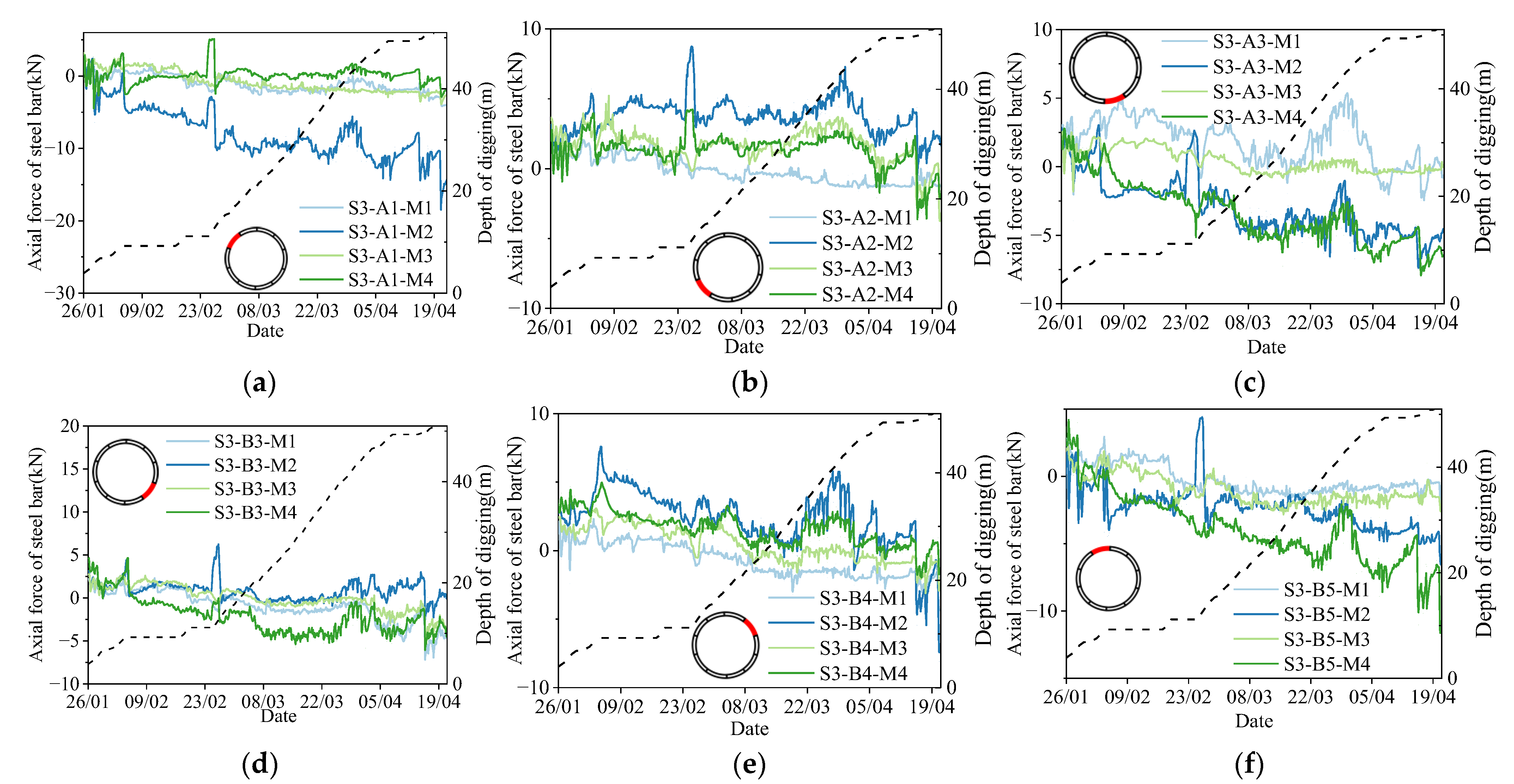
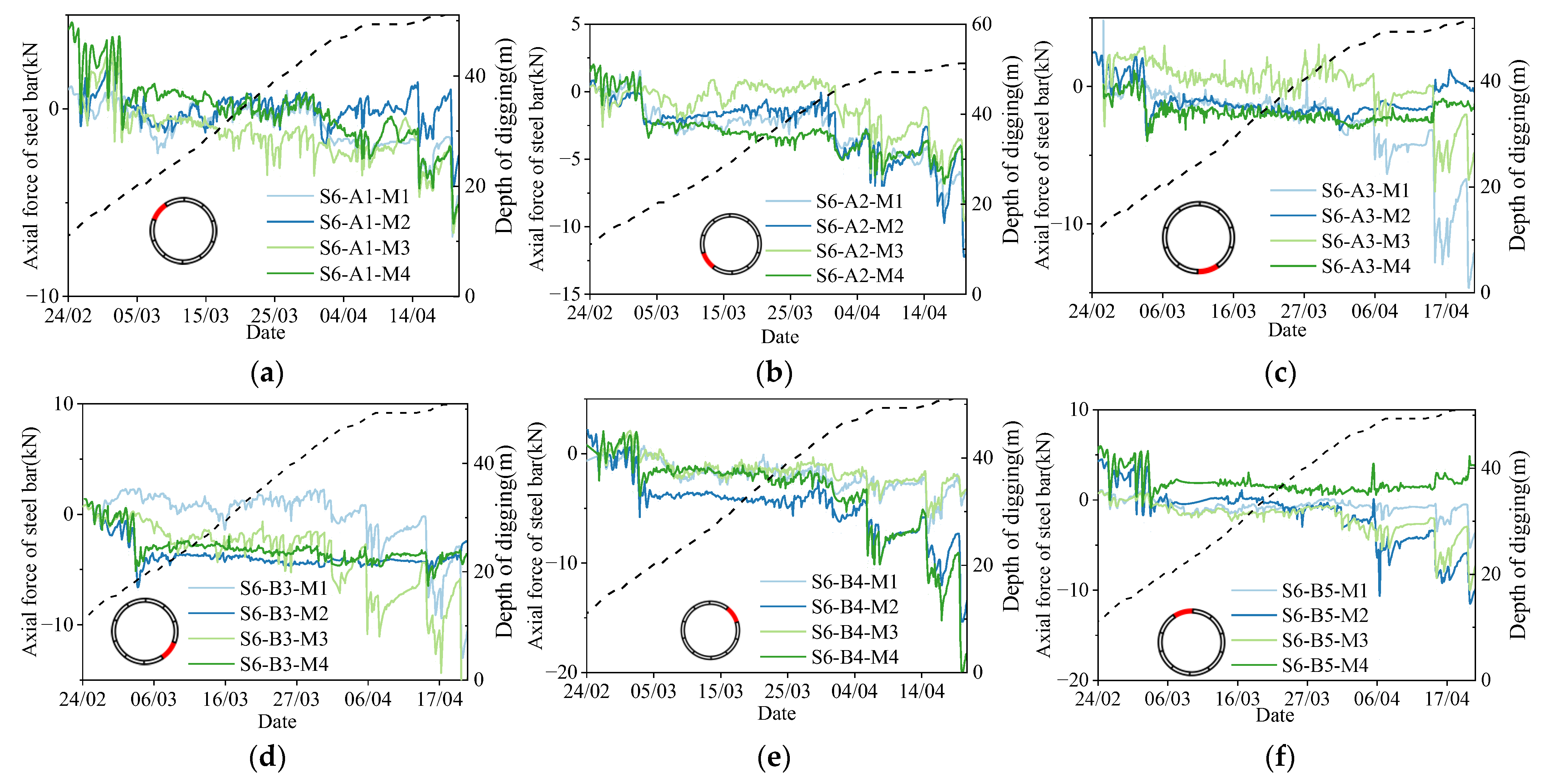
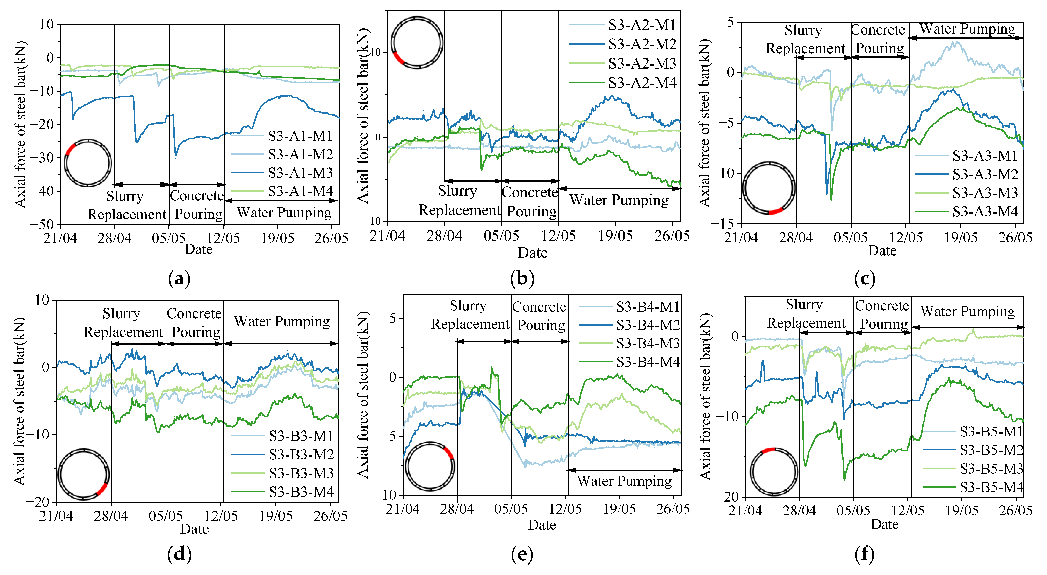
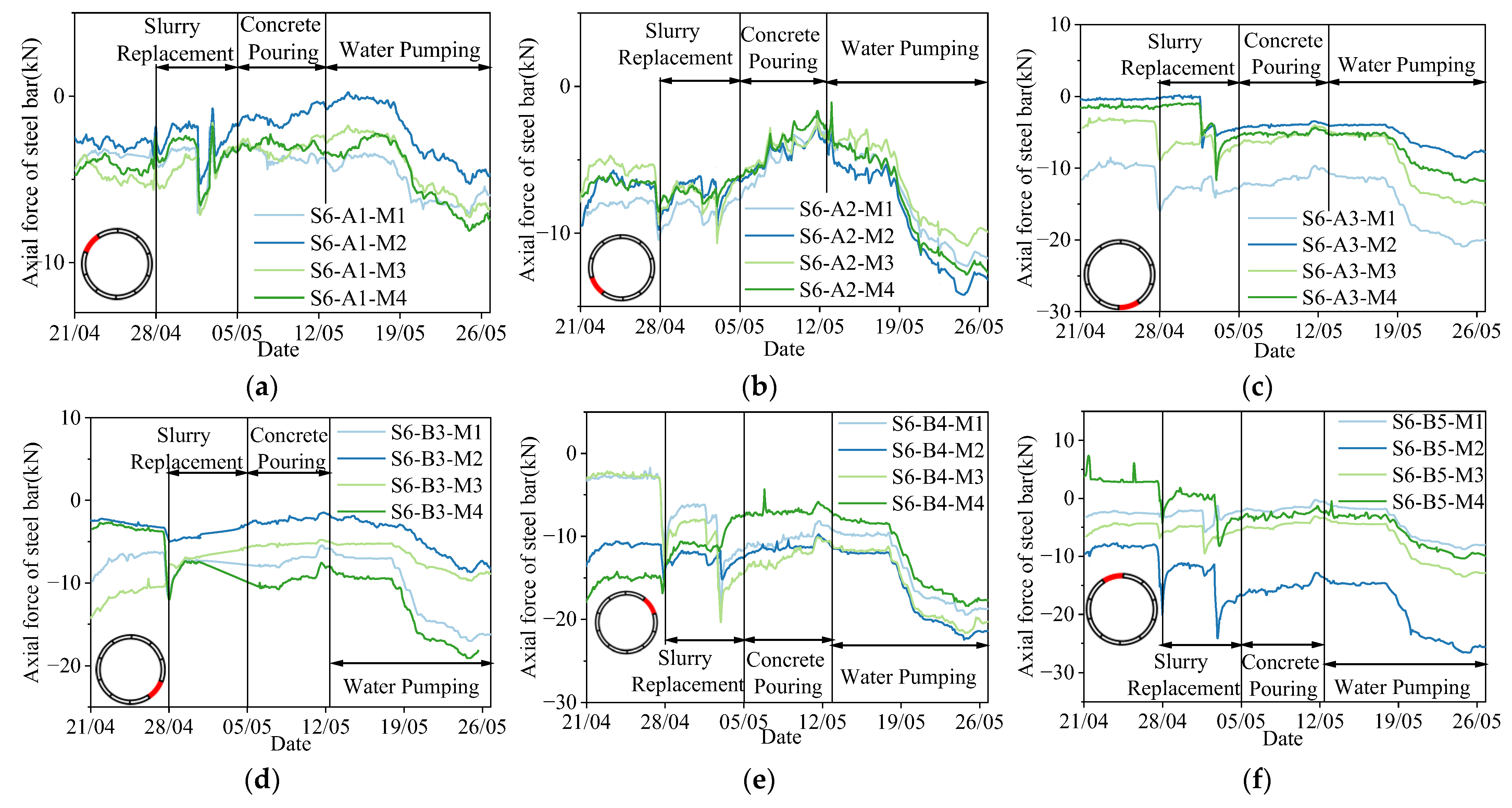
3.3. Axial Forces of Steel Bars in Shaft Segment

The variation in axial forces of steel bars within the third ring segment during stage 1 is illustrated in Figure 12. At the initial stage of digging, due to the incomplete filling of slurry between the shaft wall and surrounding soil, the resistance to shaft sinking is relatively high, resulting in significant disturbance to the shaft lining. This stage typically coincided with the simultaneous installation of newly formed segmental rings, further intensifying the disturbance to the current segment. Consequently, the axial forces recorded at various monitoring points show marked fluctuations during this stage. During the subsequent pause in digging, the structural disturbance is reduced, and the axial force of reinforcement tends to be stabilized. However, with the restarting of the digging equipment, disturbances induced by machinery lead to abrupt changes in axial forces in both the third ring segment and the bottom tie beam. As sinking continued, the axial forces in the inner arc reinforcement of the segments (measured at points M2 and M4) show a decrease and then an increase, while those on the outer arc (points M1 and M3) varied more moderately.
This complex evolution of axial forces can be interpreted through structural mechanics. During shaft sinking, the segment lining is subjected to the combined action of slurry pressure p1 on the inner surface and earth pressure p2 on the outer surface. When p1 < p2, the segment primarily experiences compressive stress. As p1 increases, especially under sustained high slurry pressures, the stress on the inner arc may gradually decrease and potentially reverse to tensile stress, thereby inducing a redistribution of internal forces within the structure.
A particularly notable period of significant axial force fluctuation occurred between 20 March and 5 April. This timeframe corresponded to the highest excavation rate, while the slurry removal system failed to maintain a corresponding level of efficiency. This results in the accumulation of mud in the shaft and a significant increase in density, especially in the bottom area of the shaft. The rapid rise in slurry pressure p1 triggered an outward expansion tendency of the shaft wall, reducing the compressive stress on the inner arc reinforcement. Following the optimization of the mucking system after 5 April, the slurry density gradually returned to normal levels, and the internal forces within the segment reinforcement correspondingly declined and stabilized. Therefore, it is necessary to be highly concerned about the mud concentration and pressure changes during shaft sinking operations. And maintaining a balanced slurry pressure is essential to prevent the induction of tensile stresses within the segment structure, thereby ensuring the segmental lining remains in a safe and stable stress state throughout construction.
The evolution of reinforcement axial forces within the sixth segment ring during stage 1 is presented in Figure 13. Similar to the third segment ring, the sixth ring experienced noticeable axial force fluctuations in the initial excavation stage due to disturbances from upper segment assembly operations. However, during subsequent continuous excavation, the axial forces remained relatively stable. This result can be attributed to the higher elevation of the sixth ring, where the surrounding slurry concentration exhibited minimal variation, as slurry predominantly accumulated at the shaft bottom. Consequently, the lateral earth pressure remained stable, resulting in limited internal force fluctuations in the segment ring. Note that around 14 April, as shaft sinking neared completion, fluctuations are observed in shaft wall pressures as well as in the axial forces of both the bottom connecting beams and the segment reinforcement. During this phase, shaft alignment corrections were performed, along with top cast-in-place construction, which likely introduced localized disturbances and triggered internal force redistribution within the structure. During this stage, shaft alignment corrections are performed, along with top cast-in-place construction, which introduces localized disturbances and triggered internal force redistribution within the structure.
In addition, it can be observed that the internal force changes of adjacent segments, such as segments A1 and B5, and A3 and B3, are actually quite similar during the sinking process. However, when observing the internal forces of the steel bars in Type A and Type B segments, respectively, it is found that the evolution trends of the internal forces of the steel bars in the two types of segments do not show obvious differences. This is because we chose to monitor the internal forces of the steel bars at the middle height of the segments, while the structural differences between Type A and Type B segments may be more reflected in the internal force distributions on their upper and lower surfaces.
Compared to the third ring, the sixth segment ring exhibited much smaller fluctuations in reinforcement axial force. This can be attributed to two main factors: (i) the shaft structure possesses high intrinsic strength and a large safety factor for support, and (ii) a near-equilibrium state is established between the internal water pressure and the external earth pressure, which significantly reduces the net load on the structure. According to structural mechanics principles, a smaller net load leads to reduced axial forces, shear forces, and bending moments, thereby enhancing structural stability during shaft excavation. In addition, the circumferential reinforcement in the sixth segment ring predominantly remained in compression, whereas the third segment ring exhibited a more complex and inconsistent stress state. As a key load-bearing component, the third ring is rigidly connected to the bottom connecting beam below and supports excavation equipment above. It is subjected to multiple influences including slurry pressure, shear force transmission, and construction-induced disturbances, which probably induce tensile stresses. The situation becomes even more intricate during equipment vibration and alignment adjustments, further complicating its stress condition.
Therefore, the design of shaft segment structures should pay particular attention to the stress and deformation characteristics of the bottom ring segment under multi-source disturbances. Ensuring that tensile openings do not exceed allowable limits under complex working conditions is critical to maintaining the structural safety and long-term durability of the shaft.
Figure 14 and Figure 15 illustrate the evolution of circumferential steel bar axial forces during stage 2. It can be observed that the slurry replacement operation from 28 April to 3 May induced short-term disturbances in the internal forces of the segment rings. Although minor fluctuations in reinforcement axial forces are observed before and after the replacement, the overall magnitude of variation remained limited. These disturbances primarily result from transient structural force redistributions caused by construction activities. Once the replacement is completed, the segment structures quickly stabilize, and the axial forces return to their previous levels. In contrast, the water pumping process initiated on 12 May become the dominant factor affecting reinforcement axial force development. As the water level within the shaft continuously decreases, the internal hydrostatic pressure on the shaft wall significantly reduces, prompting a redistribution of structural internal forces.
Notably, the third and sixth segment rings exhibit markedly different responses during water pumping. In the third ring, the steel bar compressive stress drops sharply during the initial stages of water pumping, and localized tensile stress emerges. This is followed by a gradual recovery and stabilization of compressive forces. This phenomenon can be attributed to the non-uniform deformation mechanism induced by the support action of the bottom connecting beam. Initially, areas of the connecting beam with minimal deformation experiences reduced compressive forces, while unsupported regions deform more readily. This leads to the development of localized bending moments and the emergence of tensile stress zones. As water pumping progresses, the shaft wall contracts radially, compressing the connecting beam and promoting structural coordination. Consequently, bending moments decrease and internal forces return to a primarily compressive state.
In contrast, the sixth segment ring experiences a continuous increase in reinforcement axial forces throughout the water pumping process, ultimately stabilizing at a relatively high level. As this ring is not affected by the connecting beam, it is subjected solely to the differential pressure between internal water and external soil. The reduction in internal water pressure directly increases compressive stress on the inner arc of the segment, and uniform shaft wall contraction ensures stable structural deformation.
Therefore, it can be observed that segments at different positions exhibit distinct mechanical states. In particular, for the segments near the bottom connecting beam, there is a complex and close coupling mechanism between the bottom connecting beam and the segments: On one hand, the presence of the bottom connecting beam disrupts the original uniform stress state of the segments, causing uneven deformation and inducing tensile stresses within the segments. On the other hand, this uneven deformation of the segments in turn exerts additional compressive forces on the bottom connecting beam, which to some extent suppresses the development of uneven deformation in the segments and thereby reduces the tensile stresses inside the segments. From a design perspective, it is therefore recommended to install an annular retaining wall between the bottom tie beam and the segment ring. Such a design can effectively disperse concentrated loads and suppress segment deformation heterogeneity, thereby optimizing the overall structural performance of the shaft system.

4. Monitoring Analysis of Soil Deformation

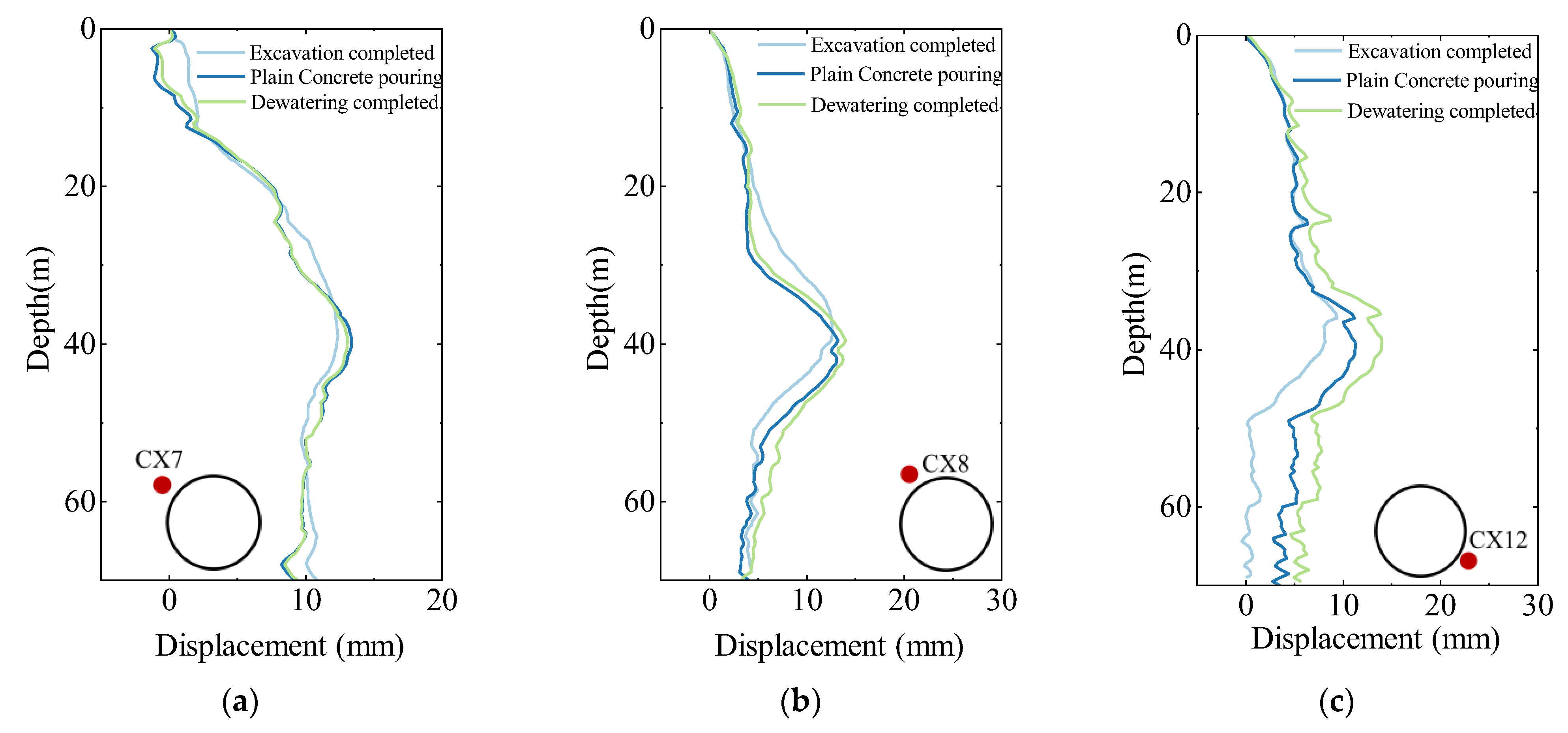
4.1. Horizontal Displacement of Cast-in-Place Piles

Figure 16 illustrates the variation in the deep horizontal displacement of the mixing piles during stage 1, with displacements defined as positive when directed toward the shaft and negative when moving away. As shown in Figure 16, with the increase in shaft sinking depth, horizontal displacements of the cast-in-place piles at all monitoring points gradually increase, displaying a typical “bulging” deformation pattern, which is consistent with the deformation pattern of the conventional pit enclosure structure.
During the initial excavation stage (0–20 m), the horizontal displacement of the cast-in-place piles increases slowly. This is attributed to the shallow excavation depth at this stage, resulting in limited disturbance to the surrounding soil. Moreover, the reinforced zone formed by the mixing piles provides effective lateral constraint, suppressing deformation development. When the excavation depth exceeds the extent of the reinforced zone (approximately 24 m), the displacement at certain monitoring points (e.g., CX6, CX9, and CX11) increases significantly, indicating a growing tendency toward instability in the lower soil layers.
Additionally, as shown in Figure 16f, during the shaft sinking depth range of 28.5–43.1 m, the CX13 monitoring point records a temporary horizontal displacement away from the shaft. This behavior is primarily due to a deviation in the shaft alignment toward the CX13 point, causing lateral compression on the adjacent pile and resulting in a reverse displacement. Following adjustments to the shaft alignment by construction personnel, the horizontal displacement of the cast-in-place pile gradually returns to the expected trend. The variation in the horizontal displacement of the cast-in-place piles during stage 2 is shown in Figure 17. One can observe that both underwater concrete pouring and water pumping operations induce changes in horizontal displacement, though the magnitude of these changes remains relatively small. Among the monitoring points considered, CX12 exhibits the most significant variation during these stages, with a peak displacement increase of approximately 5 mm. This can be primarily attributed to the reduction in internal water pressure, which leads to further contraction of the shaft wall structure and consequently causes a slight displacement of the cast-in-place piles.

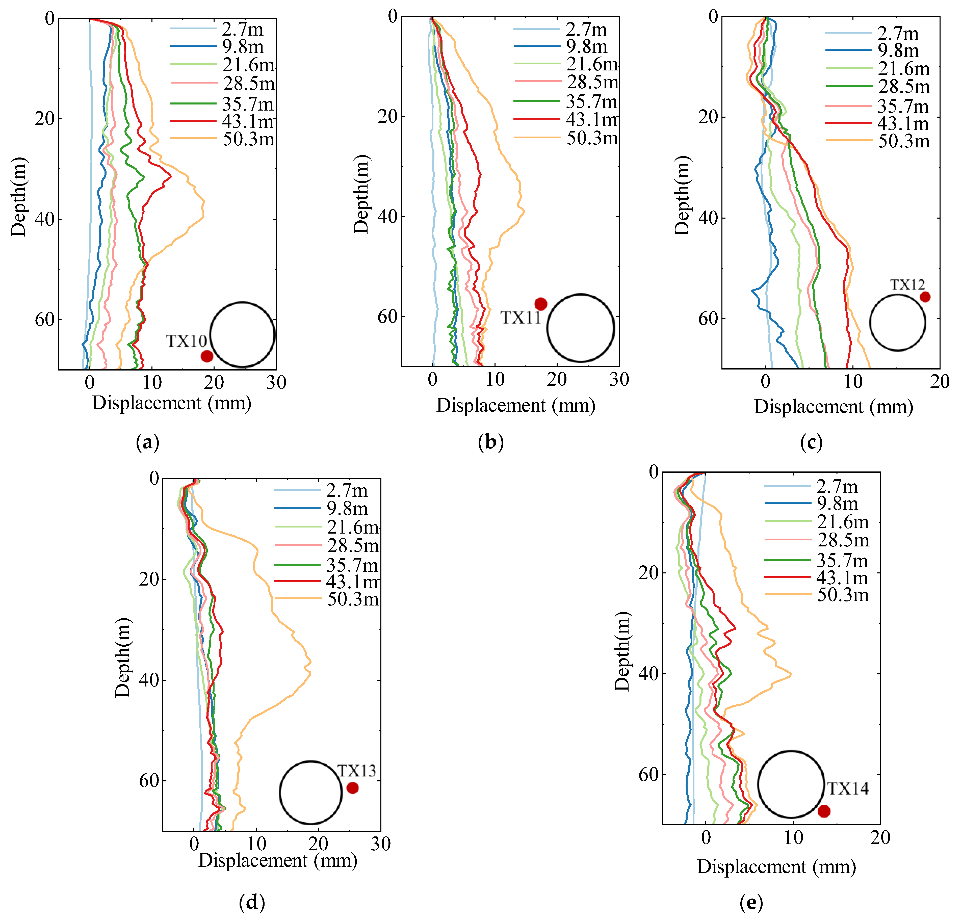
4.2. Horizontal Displacement of Deep Soil

Figure 18 illustrates the trend of the stratum horizontal displacement during stage 1, where the definition of displacement is consistent with that of the cast-in-place piles, i.e., positive towards the inside of the shaft and negative away from it. Monitoring results indicate a positive correlation between soil horizontal displacement and excavation depth. As the shaft descends, soil displacement gradually increases, reaching its peak at the bottom where disturbance effects are most pronounced. The maximum displacement at monitoring points TX10 and TX13 is approximately 18 mm, both located around 40 m below the surface, close to the depth of maximum pile deformation.
Considering the displacement characteristics of different monitoring points, significant differences can be observed. Soil displacement at TX10 and TX11 is positive, suggesting that the soil in this region generally moves toward the shaft. In contrast, monitoring points TX12, TX13, and TX14 exhibit a composite deformation pattern, where the upper soil layers move away from the shaft while the lower layers tend to move inward. The discrepancy mainly originates from the shaft inclination. Construction monitoring reveals that the shaft base tilts toward the CX13 direction, resulting in uneven lateral pressure on the surrounding soil. When the shaft inclines toward CX13, the upper section exerts greater compressive force on the opposite side (near TX12), causing the upper soil in that region to move outward. Conversely, the upper soil closer to CX13 moves inward due to the attraction effect of the shaft wall, as in the case of TX10. As the shaft inclination is corrected during construction, the non-uniform deformation induced by this misalignment is significantly alleviated, and the reverse displacement observed in the upper layers at TX13 and TX14 diminishes accordingly.
Figure 19 presents the variation in deep soil horizontal displacement during stage 2. Monitoring results indicate that both underwater concrete casting and water pumping operations induce additional soil deformation, particularly in the deep layers below 40 m, where displacement shows a further increasing trend. This is primarily attributed to the reduction in internal water pressure during water pumping, which leads to slight shrinkage of the shaft wall structure and imposes additional disturbance on the surrounding soil. Notably, the increase in displacement during this state is limited and gradually stabilizes over time. This suggests that the shaft wall continues to provide effective support, progressively constraining the overall deformation of the shaft within a reasonable range and allowing the structural system to reach a stable state.

5. Conclusions

This study presents a comprehensive real-time monitoring investigation of the mechanical response of key structural components and surrounding strata during the sinking, bottom pouring, and water pumping stages of a shaft constructed by a VSM. The monitoring focuses on the dynamic evolution of critical parameters, including the axial forces in the reinforcement of the bottom tie beams, the external pressure of segment rings, the axial forces in the circumferential reinforcement of the segments, and the horizontal displacements of adjacent cast-in-place piles and surrounding strata. Based on the analysis of field monitoring data, the major conclusions are summarized as follows.
(1) The external pressure of the shaft exhibits clear depth dependence and stage-specific evolution during excavation. At the initial stage, the pressure is minimal and gradually increases with excavation depth, reaching a stable value when the shaft bottom is approached. During bottom concrete pouring and subsequent water pumping, the rapid reduction in internal water pressure causes slight inward contraction of the shaft wall, weakening the counteracting soil pressure and shifting the external stress state toward the active earth pressure limit.
(2) The axial force in the reinforcement of the bottom connecting beams remains predominantly compressive throughout the excavation process, with the force level increasing significantly during shaft sinking and water pumping. Notable spatial differences in axial forces are observed among different monitoring points, particularly under the constraint of the bottom ring beam. These differences highlight the three-dimensional and zonal characteristics of structural response at the shaft base.
(3) The axial force in segmental reinforcement evolves dynamically in response to construction activities, significantly influenced by segment assembly disturbances, slurry pressure fluctuations, and boundary conditions. A characteristic “fluctuation–recovery–stabilization” pattern is observed. The bottom ring segment exhibits a more complex stress state due to the combined effects of the rigid bottom tie beam connection and excavation disturbance. Local tensile stresses may occur, indicating the need for special attention to cracking resistance and deformation control in structural design.
(4) The horizontal displacement of cast-in-place piles and surrounding strata increases with shaft depth during sinking, forming a typical “bulging” deformation profile, with peak displacements concentrated at depths of 35–40 m. Shaft inclination further induces localized displacement away from the shaft in piles and strata. Additionally, bottom pouring and water pumping operations cause measurable disturbance to the soil–structure system, especially in deeper layers (below 40 m). However, the overall displacement increase remains limited and stabilizes in the later stages of construction, indicating that the shaft structure maintains good deformation resistance and mechanical adaptability after internal water pressure is relieved.
This study provides an integrated insight into the coupled mechanical response of shaft structures and surrounding soils under complex construction conditions, offering field-based evidence for segment stress evolution and deformation coordination mechanisms. The findings contribute to refining the design and control strategies for deep shaft construction. Future research may focus on the long-term performance of segmental linings under operational loads and explore intelligent monitoring methods for real-time risk prediction and control.

Author Contributions

Conceptualization, H.B. and Y.L.; Methodology, H.B. and X.W.; Validation, X.W.; Investigation, Z.X., L.Y. and X.Z.; Resources, Y.L.; Data curation, H.B., X.W. and Y.L.; Writing—original draft, H.B.; Writing—review & editing, X.W. and Y.L.; Supervision, Z.X., L.Y. and X.Z.; Project administration, Y.L.; Funding acquisition, Z.X., L.Y. and X.Z. All authors have read and agreed to the published version of the manuscript.

Funding

This research was funded by the key Research Project of the Department of Housing and Urban-Rural Development of Shanghai Municipality (2023-Z02-010).

Data Availability Statement

The authors confirm that the data supporting the findings of this study are available within the article.

Conflicts of Interest

The authors declare no conflict of interest.

References

  1. Wang, J.; Abbasi, N.S.; Pan, W.; Alidekyi, S.N.; Li, H.; Ahmed, B.; Asghar, A. A Review of Vertical Shaft Technology and Application in Soft Soil for Urban Underground Space. Appl. Sci. 2025, 15, 3299. [Google Scholar] [CrossRef]
  2. Ong, D.E.L.; Barla, M.; Cheng, J.W.-C.; Choo, C.S.; Sun, M.; Peerun, M.I. Deep Shaft Excavation: Design, Construction, and Their Challenges. In Sustainable Pipe Jacking Technology in the Urban Environment: Recent Advances and Innovations; Springer: Singapore, 2022; pp. 103–145. ISBN 978-981-16-9372-4. [Google Scholar]
  3. Leung, C.F.; Shen, R.F. Performance of Gravity Caisson on Sand Compaction Piles. Can. Geotech. J. 2008, 45, 393–407. [Google Scholar] [CrossRef]
  4. Matsumoto, T.; Gomi, N.; Ikemi, Y. Process for improving open caisson, ‘SS caisson process’ Open keson no kairyo koho ‘SS keson koho’. Denryoku Doboku (Electr. Power Civ. Eng.) 1997, 270, 100–102. [Google Scholar]
  5. Wang, Y.; Liu, M.; Liao, S.; Yi, Q.; He, J.; Liu, L.; Gong, Z.; Li, K. Investigation on the Stratigraphic Response and Plugging Effect Induced by Press-In Open Caisson in Mucky Soil. KSCE J. Civ. Eng. 2023, 27, 1928–1941. [Google Scholar] [CrossRef]
  6. Tani, Y.; Nakano, M.; Okoshi, M.; Maeda, S.; Isa, H. Research & Development of Automatic System for Open Caisson Method. In Proceedings of the 13th ISARC, Tokyo, Japan, 11–13 June 1996. [Google Scholar] [CrossRef]
  7. Tanimura, D.; Ueda, J.; Tani, Y. Large-scale vertical shaft excavation using super-open caisson system. Construction of Tamasato vertical shaft (Ishioka vertical shaft No.5); Jidoka open caisson koho ni yoru daikibo tatekui no kussaku. Tamasato tateko (Ishioka dai5 tateko) shinsetsu koji. Kensetsu No Kikaika 1998, 581, 9–14. [Google Scholar]
  8. Frenzel, C.; Delabbio, F.; Burger, W.; Potvin, Y. Shaft Boring Systems for Mechanical Excavation of Deep Shafts; Australian Centre for Geomechanics: Perth, Australia, 2010; pp. 289–295. [Google Scholar]
  9. Peila, D.; Viggiani, G.; Celestino, T. Tunnels and Underground Cities. Engineering and Innovation Meet Archaeology, Architecture and Art: Proceed-ings of the WTC 2019 ITA-AITES World Tunnel Congress (WTC 2019), 3–9 May 2019, Naples, FL, USA; CRC Press: Boca Raton, FL, USA, 2019. [Google Scholar]
  10. Neye, E.; Burger, W.; Rennkamp, P. Rapid shaft sinking. Min. Rep. 2013, 149, 250–255. [Google Scholar] [CrossRef]
  11. Schmäh, P. Vertical Shaft Machines. State of the Art and Vision. Acta Montan. Slovaca 2007, 12, 208–216. [Google Scholar]
  12. Jiang, H.; Bao, H.; Lin, Y. Research and Application of Design and Construction Technology of Assembled Shaft: A Case Study of a Sinking Shaft Underground Parking Garage in Nanjing, China. Tunn. Constr. 2022, 42, 463–470. [Google Scholar]
  13. Khine, H.Y.; Marcus Tong, S.Y.; Chen, Y.K. The First Circular Shaft in Asia with the Use of Vertical Shaft Sinking Machine. In Proceedings of the ITA-AITES World Tunnel Congress, Copenhagen, Denmark, 2–8 September 2022. [Google Scholar]
  14. Schmäh, P.; Berblinger, S. VSM Shaft Sinking Technology: Mechanized Shaft Sinking with the VSM in Different Projects for Subway Ventilation Shafts. In Proceedings of the World Tunnel Congress 2014—Tunnels for a Better Life, Iguassu Falls, Brazil, 9–15 May 2014; Volume 3, p. 123. [Google Scholar]
  15. Mingliang, H.; Zhenguang, Z.; Jie, X.; Hong, J.; Heli, B.; Xian, L. Measuring of Shaft Wall Stress in Caisson Construction Process Based on Vertical Shaft Sinking Machine: A Case Study of Caisson-Type Underground Intelligent Parking Garage Project in Nanjing, China. Suidao Jianshe (Zhong Ying Wen) 2022, 42, 1033–1043. [Google Scholar]
  16. Ma, C.; Hong, H.; Yu, L.; Liu, K.; Huang, J. A Numerical Study of Reinforcement Structure in Shaft Construction Using Vertical Shaft Sinking Machine (VSM). Buildings 2024, 14, 2402. [Google Scholar] [CrossRef]
  17. Liu, T.; Liu, Z.; Ma, C.; Xu, Z.; Yu, L.; Zhang, X.; Liu, K. A Numerical Analysis of the Role of Pile Foundations in Shaft Sinking Using the Vertical Shaft Sinking Machine (VSM). Buildings 2024, 14, 3383. [Google Scholar] [CrossRef]
  18. Lu, P.; Chen, F.; Nie, D.; Han, J. Analysis of Strata Deformation Patterns Induced by Vertical Shaft Sinking Machine Based on Soil Deformation Zoning: A Case Study of the Zhuyuan Bailonggang Sewage Connecting Pipe Project in Shanghai, China. Appl. Sci. 2025, 15, 1705. [Google Scholar] [CrossRef]
  19. Abualghethe, D.A.H.; Mu, B.; Dai, G.; Liu, S.; Li, Z.; Liu, S.; Han, L. Optimization of Reinforced Ring Base Depth for Vertical Shaft Sinking in Soft Soil Using VSM Method. Undergr. Space 2025, 22, 280–302. [Google Scholar] [CrossRef]
  20. Chu, J.; Ma, J.; Jiang, B.; Li, M.; Zhang, K. Experimental Study on Side Friction Distribution of Caissons during Sinking in Water. Chin. J. Geotech. Eng 2019, 41, 707–716. [Google Scholar]
  21. Templeman, J.O.; Phillips, B.M.; Sheil, B.B. Cutting Shoe Design for Open Caissons in Sand: Influence on Vertical Bearing Capacity. Proc. Inst. Civ. Eng. Geotech. Eng. 2023, 176, 58–73. [Google Scholar] [CrossRef]
  22. Guo, M.; Dong, X.; Li, J. Study on the Earth Pressure during Sinking Stage of Super Large Caisson Foundation. Appl. Sci. 2021, 11, 10488. [Google Scholar] [CrossRef]
  23. Yan, F.Y.; Shi, G. Analysis of Limiting Soil Resistance beneath Cutting Curb during Sinking of Open Caisson. Rock Soil Mech. 2013, 34, 80–87. [Google Scholar]
  24. Mu, B.G.; Bie, Q.; Zhao, X.L.; Gong, W.M. Meso-Experiment on Caisson Load Distribution Characteristics during Sinking. China J. Highw. Transp. 2014, 27, 49–56. [Google Scholar]
  25. Royston, R.; Sheil, B.B.; Byrne, B.W. Undrained Bearing Capacity of the Cutting Face for an Open Caisson. Géotechnique 2022, 72, 632–641. [Google Scholar] [CrossRef]
  26. Kim, K.-Y.; Lee, D.-S.; Cho, J.; Jeong, S.-S.; Lee, S. The Effect of Arching Pressure on a Vertical Circular Shaft. Tunn. Undergr. Space Technol. 2013, 37, 10–21. [Google Scholar] [CrossRef]
  27. Qiao, Y.; Xie, F.; Bai, Z.; Lu, J.; Ding, W. Deformation Characteristics of Ultra-Deep Circular Shaft in Soft Soil: A Case Study. Undergr. Space 2024, 16, 239–260. [Google Scholar] [CrossRef]
  28. Kim, D.S.; Lee, B.C. Instrumentation and Numerical Analysis of Cylindrical Diaphragm Wall Movement during Deep Excavation at Coastal Area. Mar. Georesources Geotechnol. 2005, 23, 117–136. [Google Scholar] [CrossRef]
  29. Wang, R.; Liu, S.; Xu, L.; Zhao, C.; Ni, P.; Zheng, W. Performance of a 56 m Deep Circular Excavation Supported by Diaphragm and Cut-off Double-Wall System in Shanghai Soft Ground. Can. Geotech. J. 2023, 60, 521–540. [Google Scholar] [CrossRef]
  30. Jia, J.; Zhai, J.-Q.; Li, M.-G.; Zhang, L.-L.; Xie, X.-L. Performance of Large-Diameter Circular Diaphragm Walls in a Deep Excavation: Case Study of Shanghai Tower. J. Aerosp. Eng. 2019, 32, 04019078. [Google Scholar] [CrossRef]
  31. Kumagai, T.; Ariizumi, K.; Kashiwagi, A. Behaviour and Analysis of a Large-Scale Cylindrical Earth Retaining Structure. Soils Found. 1999, 39, 13–26. [Google Scholar] [CrossRef]
  32. Tan, Y.; Wang, D. Characteristics of a Large-Scale Deep Foundation Pit Excavated by the Central-Island Technique in Shanghai Soft Clay. I: Bottom-Up Construction of the Central Cylindrical Shaft. J. Geotech. Geoenvironmental Eng. 2013, 139, 1875–1893. [Google Scholar] [CrossRef]
  33. Terzaghi, K. General Wedge Theory of Earth Pressure. Trans. Am. Soc. Civ. Eng. 1941, 106, 68–80. [Google Scholar] [CrossRef]
  34. Sherif, M.A.; Ishibashi, I.; Lee, C.D. Earth Pressures against Rigid Retaining Walls. J. Geotech. Eng. Div. 1982, 108, 679–695. [Google Scholar] [CrossRef]
  35. Zhao, T.; Ding, W.; Qiao, Y.; Duan, C. A Large-Scale Synchronous Grouting Test for a Quasi-Rectangular Shield Tunnel: Observation, Analysis and Interpretation. Tunn. Undergr. Space Technol. 2019, 91, 103018. [Google Scholar] [CrossRef]
Figure 1. Soil profile and geotechnical parameters along the depth.
Buildings 15 02043 g001
Figure 2. Diagram of the bottom structure of the shaft.
Buildings 15 02043 g002
Figure 3. Profile of the shaft.
Buildings 15 02043 g003
Figure 4. Shaft excavation curve.
Buildings 15 02043 g004
Figure 5. Diagram of segment monitoring point arrangement.
Buildings 15 02043 g005
Figure 6. Diagram of bottom connecting beam monitoring point arrangement.
Buildings 15 02043 g006
Figure 7. Monitoring points for horizontal movement of cast-in-place piles and the strata. (a) Horizontal piles movement monitoring points. (b) Horizontal soil movement monitoring points.
Buildings 15 02043 g007
Figure 8. External pressure during stage 1: (a) S3 and (b) S6.
Buildings 15 02043 g008
Figure 9. External pressure during stage 2: (a) S3 and (b) S6.
Buildings 15 02043 g009
Figure 10. The variation in the axial force of the steel bar in the bottom connecting beam during stage 1: (a) B-A1; (b) B-A2; (c) B-A3; (d) B-B3; (e) B-B4; and (f) B-B5.
Buildings 15 02043 g010
Figure 11. The variation in the axial force of the steel bar in the bottom connecting beam during stage 2: (a) B-A1; (b) B-A2; (c) B-A3; (d) B-B3; (e) B-B4; and (f) B-B5.
Buildings 15 02043 g011
Figure 12. The variation in the axial force of the steel bar in the third ring segment during the excavation and sinking stage: (a) S3-A1; (b) S3-A2; (c) S3-A3; (d) S3-B3; (e) S3-B4; and (f) S3-B5.
Buildings 15 02043 g012
Figure 13. The variation in the axial force of the steel bar in the sixth ring segment during the excavation and sinking stage: (a) S6-A1; (b) S6-A2; (c) S6-A3; (d) S6-B3; (e) S6-B4; and (f) S6-B5.
Buildings 15 02043 g013
Figure 14. The variation in the axial force of the steel bar in the third ring segment during the concrete pouring and water pumping stage: (a) S3-A1; (b) S3-A2; (c) S3-A3; (d) S3-B3; (e) S3-B4; and (f) S3-B5.
Buildings 15 02043 g014
Figure 15. The variation in the axial force of the steel bar in the sixth ring segment during the concrete pouring and water pumping stage: (a) S6-A1; (b) S6-A2; (c) S6-A3; (d) S6-B3; (e) S6-B4; and (f) S6-B5.
Buildings 15 02043 g015
Figure 16. Horizontal displacement of cast-in-place piles during stage 1: (a) CX6; (b) CX7; (c) CX9; (d) CX11; (e) CX12; and (f) CX13.
Buildings 15 02043 g016
Figure 17. Horizontal displacement of cast-in-place piles during stage 2: (a) CX7; (b) CX8; and (c) CX12.
Buildings 15 02043 g017
Figure 18. Horizontal displacement of the stratum during stage 1: (a) TX10; (b) TX11; (c) TX12; (d) TX13; and (e) TX14.
Buildings 15 02043 g018
Figure 19. Horizontal displacement of the stratum during stage 2: (a) TX10 and (b) TX13.
Buildings 15 02043 g019
Table 1. Examples of VSM application.
LocationDiameter/(m)Depth/(m)Shaft TypeGeological Conditions
Girona, Spain5.2520VentilationSoft ground; loamy coarse boulders
Barcelona, Spain9.247 Sand, gravel, quartz, slate
Paris, France11.945 Soft and heterogeneous ground
Honolulu, HI, USA1036Microtunneling shaftsHard basalt as well as coral
St. Petersburg, Russia7.785Sewage collector shaftsclay, sand, boulders
Dortmund, Germany9.023Launch shaftSoft ground; sand, silt, marl
Nanjing, China12.868Parking garage shaftsSand, gravel, limestone
Guangzhou, China1427Launch shaftClay, gravel, granite
Shanghai, China22.650.5Parking garage shaftsMucky clay, silty clay, silty sand
Table 2. Construction process of the shaft.
StageConstruction ProcessesDate (dd-mm-yyyy)
1Shaft excavation and sinking stage24/01/2024–21/04/2024
Construction of the cast-in-place shaft wall14/04/2024–25/04/2024
2Slurry replacement behind the shaft wall28/04/2024–03/05/2024
Underwater pouring of bottom plain concrete of the shaft07/05/2024–11/05/2024
pumping water inside the shaft11/05/2024–23/05/2024
Table 3. Monitoring point statistics.
Monitoring Points *Monitoring ItemsMonitoring TargetMonitoring AreaMonitoring Point
S3/S6-A1/A2/A3/B3/B4/B5-PExternal Pressure3rd/6th ring segmentA1/A2/A3/
B3/B4/B5
S3/S6-A1/A2/A3/B3/B4/B5-M1/M2/M3/M4Axial force of the steel bar3rd/6th ring segmentA1/A2/A3/
B3/B4/B5
M1/M2/M3/M4
B-A1/A2/A3/B3/B4/B5-M1/M2/M3/M4Bottom connecting beamA1/A2/A3/
B3/B4/B5
M1/M2/M3/M4
CX6/CX7/CX8/CX9/CX11/CX12/CX13Horizontal Deformationcast-in-place piles
TX10/TX11/TX12/TX13/TX14Horizontal DeformationStratum
* Note: “S3” and “S6” represent the segment of the third ring and the segment of the sixth ring, respectively; A1/A2/A3/B3/B4/B5 are the numbers of the segments; M1/M2/M3/M3 are the numbers of the monitoring points of axial force for each segment; P represents the external pressure monitoring point; and “CX” and “TX” represent the monitoring points for cast-in-place piles and the horizontal displacement of the stratum, respectively.
Disclaimer/Publisher’s Note: The statements, opinions and data contained in all publications are solely those of the individual author(s) and contributor(s) and not of MDPI and/or the editor(s). MDPI and/or the editor(s) disclaim responsibility for any injury to people or property resulting from any ideas, methods, instructions or products referred to in the content.

