Article

The Effect of Cementation on Microstructural Evolution and Particle Characteristics of Calcareous Sand Under Triaxial Loading

1
School of Civil and Transportation Engineering, Guangdong University of Technology, Guangzhou 510006, China
2
Guangdong Construction Engineering Quality & Safety Testing Head Station Co., Ltd., Guangzhou 510500, China
*
Author to whom correspondence should be addressed.
Buildings 2025, 15(12), 2041; https://doi.org/10.3390/buildings15122041
Submission received: 23 May 2025 / Revised: 10 June 2025 / Accepted: 12 June 2025 / Published: 13 June 2025

Abstract

:
Calcareous sands are widely distributed across the South China Sea’s continental shelf and coastlines. Understanding their mechanical behavior and microstructural evolution under cementation is critical for coastal engineering applications. While previous studies have investigated cemented calcareous sands, the comparative analyses of particle breakage and microstructural characteristics between cemented and pure sands remain limited. This study combines triaxial compression tests with X-ray CT scanning and Digital Volume Correlation analysis to systematically examine both material types. Pre- and post-loading CT scans enabled the detailed tracking of microstructural transformations. Results demonstrate that cemented specimens exhibit higher strength–stiffness properties with strain-softening behavior compared to pure sand under 200 kPa confining pressures. A quantitative analysis revealed greater particle breakage in cemented sand, while pure sand showed more pronounced increases in particle sphericity and the aspect ratio during deformation, accompanied by reduced porosity variation along specimen height (coefficient of variation decreased from 15.2% to 12.8% for pure sand. Microstructural analysis indicated moderate increases in pore sphericity and reduced anisotropy in both materials. Fractal dimension analysis demonstrated more significant structural reorganization in cemented sands. Both materials exhibited increases in key morphological parameters, including the throat equivalent radius, channel length, pore equivalent radius, and coordination number, with changes being more substantial in cemented sands. Within shear band regions, cemented sands displayed marked reductions in pore and throat quantities. These findings elucidate fundamental relationships between cementation effects and micro–macro mechanical responses, providing theoretical support for geotechnical applications involving calcareous sands.

1. Introduction

With the advancement of offshore island and reef engineering projects, the investigation of the geo-mechanical properties of coral sand and the development of associated ground improvement techniques have become increasingly critical areas of research. Coral sand, primarily composed of coral fragments and other marine biogenic materials, contains more than 90% calcium carbonate and is classified as a type of calcareous sand. Compared to quartz sand, calcareous sand is characterized by irregular particle shapes, high internal porosity, susceptibility to particle breakage, and relatively low strength. These unique properties result in mechanical behavior that differs significantly from typical terrigenous sands [1,2,3,4,5]. Furthermore, naturally cemented calcareous sand presents additional challenges, including non-uniform cementation distribution, structural sensitivity, and the complex environmental conditions of offshore islands and reefs. The difficulty and high costs of obtaining undisturbed samples further hinder progress in understanding its mechanical properties [6]. Currently, common methods for preparing cemented calcareous sand include cement- and gypsum-based cementation, as well as advanced calcium carbonate precipitation techniques, such as chemically induced precipitation (CIPS) and microbially induced calcium carbonate precipitation (MICP) [7,8,9,10,11].
Various studies have examined the mechanical properties of cemented sands through experimental work. Many researchers [12,13,14,15] developed formulations for unconfined compressive strength that account for critical factors, including the curing period, porosity, and cement concentration. Through a combination of laboratory triaxial testing and DEM simulation techniques, Li and Chen demonstrated that increasing cement content correlates with greater particle breakage and enhanced dilation tendency [16]. Their work established that both the variety and strength characteristics of cementing agents play crucial roles in determining the overall strength and yield patterns of cemented soils. Further research by Liu and Dong explored the structural composition of cementing agents within cemented sands, determining that expanding the cementation radius ratio strengthens inter-particle constraints and develops more robust force chain networks [17]. This enhancement manifests as higher peak stress ratios and characteristic stress-softening behavior, while simultaneously increasing the soil’s brittle properties.
Particle breakage is a common phenomenon in granular soils, particularly in coral sand, and significantly influences particle properties [18,19,20,21]. Wu et al. conducted a series of one-dimensional compression tests on calcareous sand, demonstrating that particle breakage increases compressibility while reducing stiffness during the compression [22]. According to Yu, coral sand samples subjected to different levels of axial strain in multiple triaxial tests were analyzed using mechanical sieving to quantify the extent of particle breakage [23]. Triaxial tests on calcareous sand revealed that the degree of particle fragmentation increases with higher initial density and greater confining stress [22]. Drained shear tests on sand particles conducted under high confining pressures and analyzed using computed tomography (CT) imaging revealed a significant particle breakage within the shear band [24]. Advanced micro-CT imaging techniques have also been used to investigate particle movement, rotation, fragmentation, and the formation mechanisms of shear bands during triaxial tests [25]. Recent studies on individual calcareous sand particles coated with cement material by MICP have identified distinct fragmentation modes, including explosive crushing, mixed crushing, and splitting. These modes are strongly influenced by the calcium carbonate coating, which increases single-particle strength and leads to fractures producing larger fragments [26].
Particle breakage causes significant changes in particle morphology. At the micro-scale, particle fracture occurs through various mechanisms, including splitting, explosion, explosive splitting, and chipping [27]. These breakage modes of single particles significantly influence particle shape parameters, such as the aspect ratio and sphericity [28,29,30]. According to Wei et al., particle fragmentation significantly changes particle morphology during triaxial tests. The results showed that particle breakage leads to an increased fraction of finer particles, which enhances inter-particle interlocking and friction. Additionally, the fractured particles tend to have a more spherical shape and smoother surface textures [31]. Zhang et al. conducted one-dimensional compression tests on calcareous sand, revealing a tendency for particles to obtain a more spherical morphology after compression [32]. The evolution of particle morphology under large-strain-shearing conditions has also been investigated, showing that particles gradually become more rounded after tests [33].
Loading conditions induce substantial changes in pore structure for geo-materials. To analyze these internal structural evolutions, particularly pore characteristics, researchers increasingly combine optical imaging technologies with conventional geotechnical instruments for microstructural investigation. Among these techniques, computed tomography (CT) imaging is widely used due to its capability for the high-resolution, real-time, and non-destructive analysis of arbitrary cross-sections. For example, Shi et al. used CT imaging to investigate the pore structure characteristics of mortar and evaluated their influence on its mechanical properties [34]. Similarly, Yuan et al. applied CT scanning to study calcareous sand and silica sand columns, developing pore network models to analyze the impact of pore characteristics on slurry permeability [35]. Ji et al. used three-dimensional CT reconstructions to extract pore characteristics, including connectivity, porosity, pore radius, and coordination number, in order to quantitatively evaluate the influence of calcium carbonate content on the microstructure of biologically cemented sand [36]. Furthermore, CT imaging technology enables the quantification of sand particle parameters [37] and facilitates the investigation of the strength and deformation characteristics of geo-materials under loading [38]. Karatza et al. applied micro-CT imaging to study particle movement, rotation, fracturing, and shear band formation during the triaxial testing of sand particles [25]. Cheng et al. integrated a micro-triaxial testing apparatus with micro-CT imaging and advanced image processing techniques to conduct non-destructive evaluations of the micro-mechanical behavior for coral sand under triaxial shear conditions, focusing primarily on particle morphology and local strain evolution during loading [39]. Charalampidou et al. conducted triaxial compression experiments on porous sandstone, incorporating acoustic wave monitoring, CT scanning, electron microscopy, and computational image processing to investigate multi-scale deformation mechanisms, including shear band formation, compaction bands, particle crushing, and porosity evolution [40].
Current research on the microstructural characteristics of calcareous sand under loading predominantly emphasizes the mechanical behavior of individual particles at the micro-scale. However, a comprehensive understanding of the effect of cementation on the particle breakage and microstructural evolution remains critical for a better understanding of the mechanical behavior of calcareous sand. In this study, triaxial tests were conducted on calcareous sand using computed tomography (CT) scanning technology and Digital Volume Correlation (DVC) technology to investigate the change in particle morphology and inter-particle pore characteristics within the specimens after loading. In addition, cemented calcareous sand specimens were also tested to evaluate the effects of cementation on particle breakage, morphological evolution, and microstructural development.

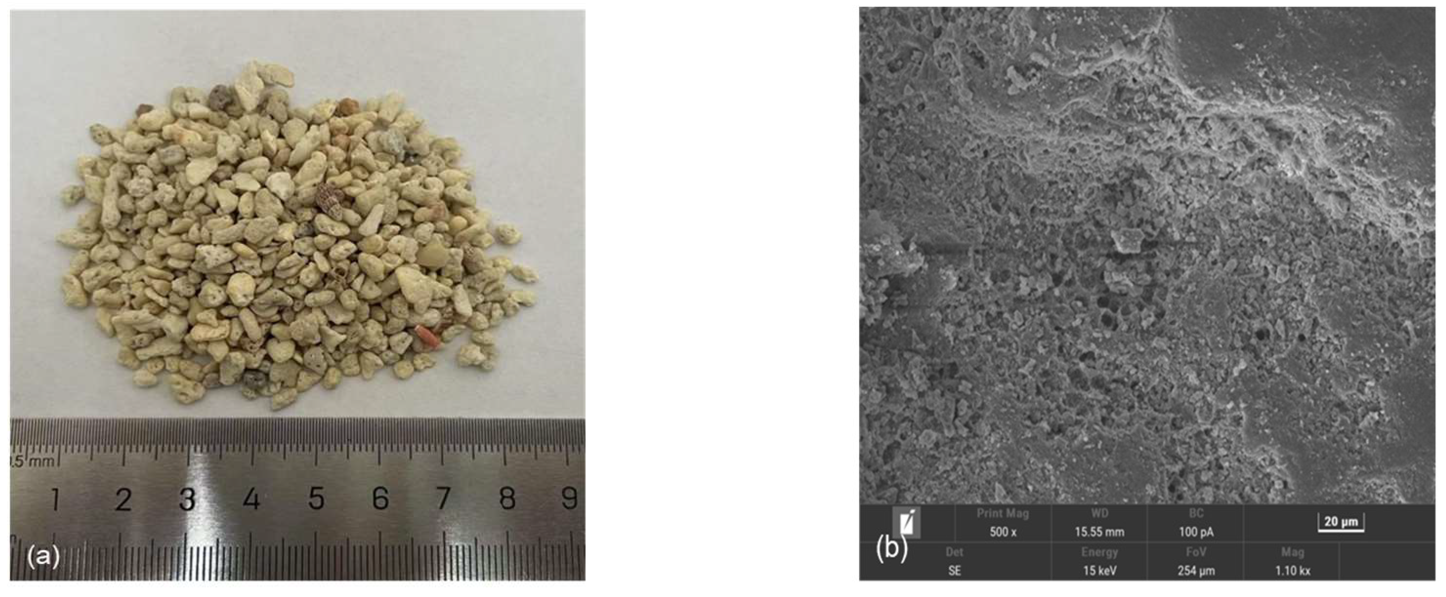
2. Materials and Methods

The sand used in this study was loose and uncemented calcareous sand collected from a reef in the South China Sea. As shown in Figure 1a, the calcareous sand is characterized by the gray white color, irregular particle shapes, and visible surface pores, resulting from their biogenic origin. The scanning electron microscopy (SEM) image (Figure 1b) reveals that the particles have high surface roughness, intricate microstructures, and complex internal porosity, which significantly influence their mechanical behavior. The calcareous sand samples were oven-dried to ensure a completely dry state before sieving. Particles with diameters ranging from 1.18 to 2.36 mm were selected for tests and further analysis. The selection of particles with diameters ranging from 1.18 to 2.36 mm was specifically designed to optimize the balance between CT scanning resolution requirements and representative particle behavior analysis. Given the CT system’s spatial resolution of 7.671 μm per voxel, particles smaller than 1.18 mm would contain insufficient voxels for accurate morphological characterization, while the upper limit of 2.36 mm ensures adequate sample quantity within the specimen dimensions. It must be admitted that a limitation exists when extrapolating findings to natural calcareous sand deposits with broader particle size distributions. The basic physical properties of the calcareous sand are summarized in Table 1.
β-type construction gypsum was used as the cement agent in the experiment based on several technical considerations optimized for microstructural analysis objectives. Unlike microbially induced calcium carbonate precipitation (MICP) or enzymatically induced calcium carbonate precipitation (EICP), gypsum provides the following: (1) controlled and reproducible cementation kinetics essential for consistent specimen preparation; (2) uniform distribution throughout the specimen; (3) stable chemical composition that does not interfere with CT imaging contrast; and (4) appropriate density contrast with calcareous sand particles for accurate CT-based segmentation. Its rapid initial setting time of approximately 6 min posed challenges during specimen preparation, potentially leading to localized particle clusters and compromising the homogeneity of the gypsum-cemented calcareous sand specimens. To extend the initial setting time of the gypsum, a novel gypsum retarder was added (0.2% by weight of gypsum). This retarder extends the initial setting time from 6 min to approximately 25 min, providing adequate working time for uniform specimen preparation while maintaining the mechanical properties of the gypsum-cemented calcareous sand specimens.
The triaxial specimens were prepared with dimensions of 39.1 mm in diameter and 80 mm in height. The different relative densities were selected to represent realistic field conditions: 45% for natural loose calcareous sand deposits and 70% for ground-improved cemented sand. While this density difference may influence absolute mechanical properties, our primary focus is on microstructural evolution patterns rather than direct strength comparisons. The higher density in cemented sand partially compensates for the potential porosity effects of cementation, providing a more representative comparison of cemented versus uncemented behavior in practical applications. The sample preparation process used a layered compaction method, in which the specimen was compacted in five layers with equal masses to ensure uniform density distribution. For the cemented specimens, gypsum plaster and distilled water were mixed at a mass ratio of 1:1 until homogeneous. The prepared specimen and saturators were then cured in a temperature–humidity-controlled chamber for 72 h. To facilitate subsequent analysis, the uncemented sand specimens were designated as pure sand before test (PSBT) and pure sand after test (PSAT) for their before and after test conditions, respectively. Similarly, the gypsum-cemented sand specimens are referred to as cemented sand before test (CSBT) and cemented sand after test (CSAT) for the corresponding conditions.
For the triaxial compression tests, the pressure chamber was filled with water and preloaded to 20 kPa, followed by backpressure saturation. The specimen was considered fully saturated when the coefficient of saturation exceeded 95%. Following fully saturation, the specimen was isotropically consolidated until the volumetric strain stabilized. Subsequently, the specimen was sheared at a strain rate of 0.01 mm/min under an effective confining pressure of 200 kPa, until reaching an axial strain of 20%. X-ray computed tomography (CT) scans were performed using a Phoenix v|tome|x m industrial CT system (Baker Hughes, Houston, TX, USA) (Figure 2) on both pure and cemented calcareous sand specimens before and after triaxial shearing. The fundamental principle of computed tomography (CT) scanning involves the production of a broad-spectrum X-ray beam generated by the interaction of an electron beam, emitted from the cathode, with a tungsten anode target. The X-rays traverse the rotating sample at various angular positions and are captured as two-dimensional projection images by a detector. These projection images are subsequently reconstructed into a three-dimensional model using specialized 3D analysis software. During the scanning process, the temperature is maintained at 293 K. The X-ray generator operates at a voltage of 170 kV and a current of 85 μA, with a camera readout rate of 2.5 MHz. For each specimen, a total of 2000 slices were continuously acquired along the sample’s height direction, and the spatial resolution achieved was 7.671 μm per voxel.
The visualization and analysis software Avizo 2019 was used for the three-dimensional reconstruction and quantitative analysis of the CT data. The software enabled comprehensive microstructural characterization through a series of image processing algorithms. Prior to segmentation, digital filtering was applied to minimize grayscale artifacts and noise, thereby preventing over-segmentation during watershed transformation (Yuan et al., 2024 [35]). Following noise reduction, the grayscale images were binarized, and a Chamfer distance transform was computed to quantify the spatial relationships between particle domains and void space. The resulting distance field was inverted and hierarchically sorted to establish regional markers for watershed-based segmentation. As illustrated in Figure 3, this segmentation approach enabled the three-dimensional reconstruction of particles, cementation, and pore networks in this case. Subsequent morphology analyses were performed using the Label algorithm to quantify the geometric and spatial characteristics of individual features, including the shape factors, anisotropy indices, and spatial distribution of both pores and particles.
Sphericity S is a parameter that quantifies the degree to which a particle’s shape approximates that of a perfect sphere. It is defined as the ratio of the surface area of a sphere with the same volume as the particle to the actual surface area of the particle [41]. The value of sphericity can be determined by Equation (1) as follows:
S = ( 36 π V 2 ) 1 / 3 A
where V and A denote the volume and surface area of an individual pore or particle, respectively. This dimensionless index ranges from 0 to 1, where 1 represents a perfect sphere. Fernlund used image processing techniques to analyze particle projections on two orthogonal planes [42]. Through this analysis, the dimensions of the principal axes in three-dimensional space were determined, enabling the calculation of the aspect ratio AR to quantify particle elongation in granular materials, as defined in Equation (2):
A R = E I + F I 2
where EI denotes the elongation index, EI = b/a, FI represents the flatness index, and FI = c/a. a, b, and c represent the length of the major, intermediate, and minor axes, respectively. A particle is considered spherically symmetric when its AR equals 1.
The morphological parameters employed in this study were specifically selected for their relevance to calcareous sand behavior and marine engineering applications. Sphericity and the aspect ratio are particularly applicable to calcareous sand due to its biogenic origin and inherently irregular particle shapes. These parameters directly relate to engineering properties: increased sphericity typically correlates with improved flow characteristics and reduced inter-particle friction, while aspect ratio changes affect stress transmission and shear strength development.
Following watershed segmentation for individual particle identification, particle size distribution (PSD) analysis was performed to evaluate the influence of cementation on particle breakage behavior under loading conditions. The degree of particle breakage was quantified using the relative breakage index Br, defined by Hardin and Bobby as the ratio of total breakage Bt to breakage potential Bp [43], as expressed in Equation (3):
B r = B t B P
where Bt represents the area between the initial and final grain size distribution curves, and Bp denotes the area enclosed by the initial particle size distribution curve and the vertical line at a particle size of 0.074 mm.
Anisotropy serves as an indicator for identifying the structural alignments along a specific directional axis. This measurement methodology is founded on an eigenvalue analysis of the mean intercept length (MIL) measured at different angular orientations. The MIL method projects oriented rays through a binary image at discrete angles, using a systematic grid pattern. With a fixed pitch angle of 10 degrees, the procedure measures and averages the intersection length between rays and material boundaries. The resulting angular distribution of mean intercept lengths undergoes eigenvalue decomposition to characterize the directional dependencies of material. In this study, the anisotropic behavior can be quantified in Equation (4):
F = 1 λ m i n λ m a x
where λmin and λmax are the minor and major eigenvalues, respectively. When 0 < F < 1, the material shows anisotropy; when F = 0, it is isotropic.
Digital Volume Correlation (DVC) is a sophisticated image analysis technique based on optical flow principles that enables the measurement of three-dimensional displacement and strain fields within specimens subjected to different loading conditions. Since its initial implementation, DVC has evolved significantly, with numerous algorithms developed to improve the measurement accuracy and precision. In this study, two distinct methodologies were used to quantify the displacement and strain fields: a conventional subset-based approach and an advanced finite-element technique (Figure 4) [44,45]. In addition, the maximal ball cluster structure was systematically organized to identify distinct pores and throats based on their spatial relationships and dimensional characteristics. The pore network was conceptualized using a ball-and-stick model, where interconnected pores were linked through throats. In this model, balls denoted pores, while their interconnections represented throats. The equivalent radii of both pores and throats were derived from the corresponding maximal ball radii. In this case, the coordination number was defined as the quantity of distinct throats intersecting at a single pore [46].

3. Results and Discussion

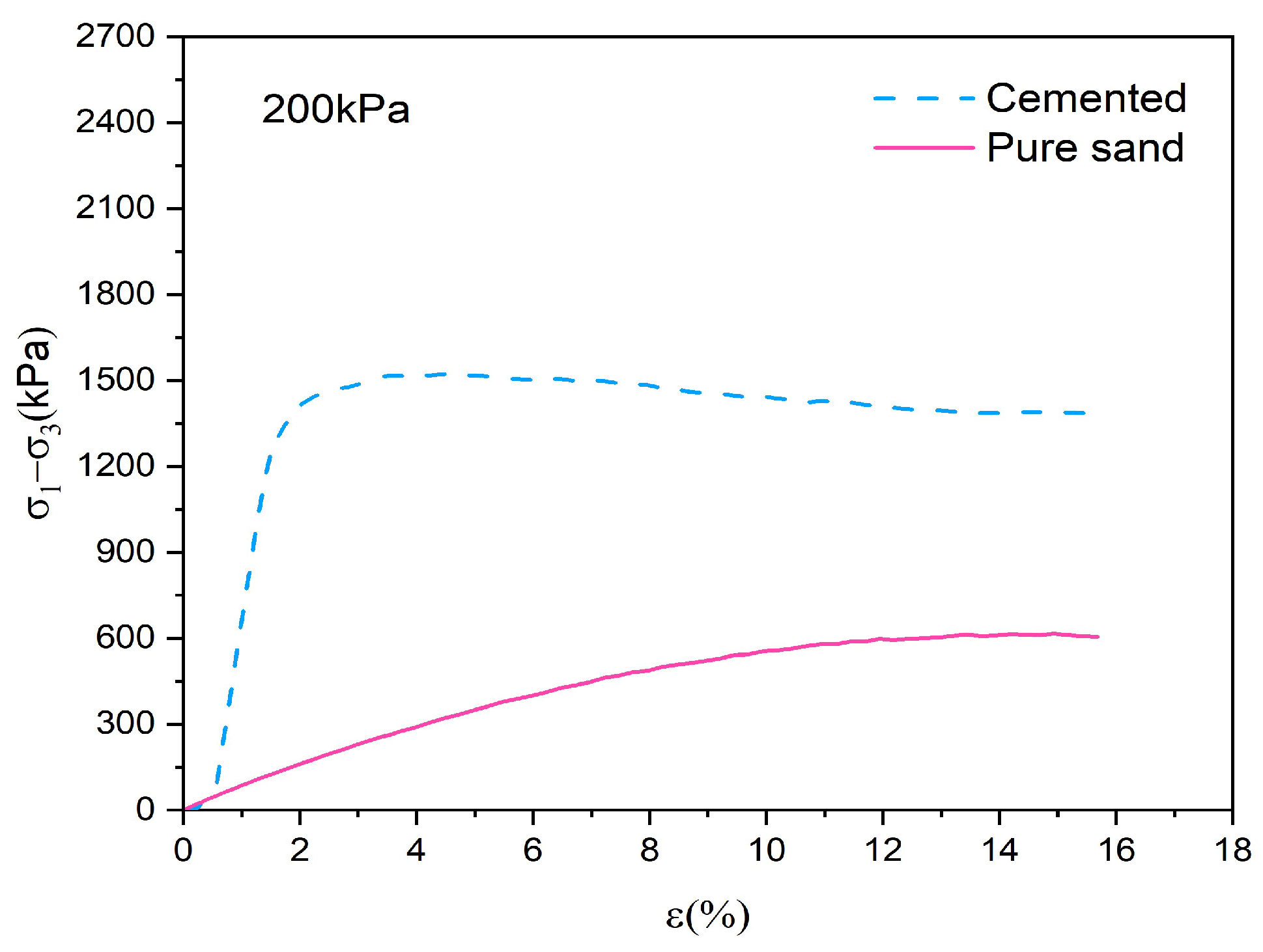
3.1. Mechanical Response and Particle Breakage for Pure and Cemented Calcareous Sand

Figure 5 shows the significantly different mechanical behaviors between pure and cemented calcareous sand during triaxial tests under 200 kPa confining pressure. Cemented sand demonstrates much higher strength (i.e., peak deviator stress around 1500 kPa) and greater stiffness, reaching its peak strength at a relatively small strain (approximately 2–4%) followed by a slight strain-softening behavior. In contrast, the pure calcareous sand shows typical strain-hardening behavior with a much lower ultimate strength (around 600 kPa). This mechanical behavior can be attributed to the cementation bonds providing additional cohesion and interlocking between particles in the cemented sand. The bonds significantly restrict particle rotation and rearrangement, resulting in developed force chains and a more stable microstructure.
Comparing the particle size distribution curves of pure and cemented calcareous sand in Figure 6, a notable leftward shift could be observed for the cemented sand curve, indicating that the cemented particles experienced more significant particle breakage during triaxial tests compared to pure sand. The relative breakage rates Br, calculated using Hardin’s breakage theory, are 8.7% for pure calcareous sand and 9.5% for cemented sand. In pure sands, individual particles could rotate and redistribute stress more freely, undergoing rearrangement rather than significant breakage during loading. In contrast, the presence of gypsum as a cementing agent in cemented calcareous sand facilitates the formation of shear bands. Under shear stress, stress concentration develops near the shear bands, leading to increased particle breakage and the failure of cementation bonds or layers. Alikarami et al. demonstrated that particle breakage predominantly occurs within the shear band during triaxial testing, with gypsum cementation playing a critical role in shear band development [24]. Similarly, Karatza et al. found that elevated stress levels promote particle compaction and intensified shearing [25]. Once particle breakage is initiated, the specimen undergoes dilation within the shear band, resulting in increased maximum shear strain and more particle breakage. The conclusion reveals that while cementation increases strength, it also makes the soil structure more susceptible to particle breakage under loading conditions, which is an important consideration in engineering applications, especially for long-term stability.

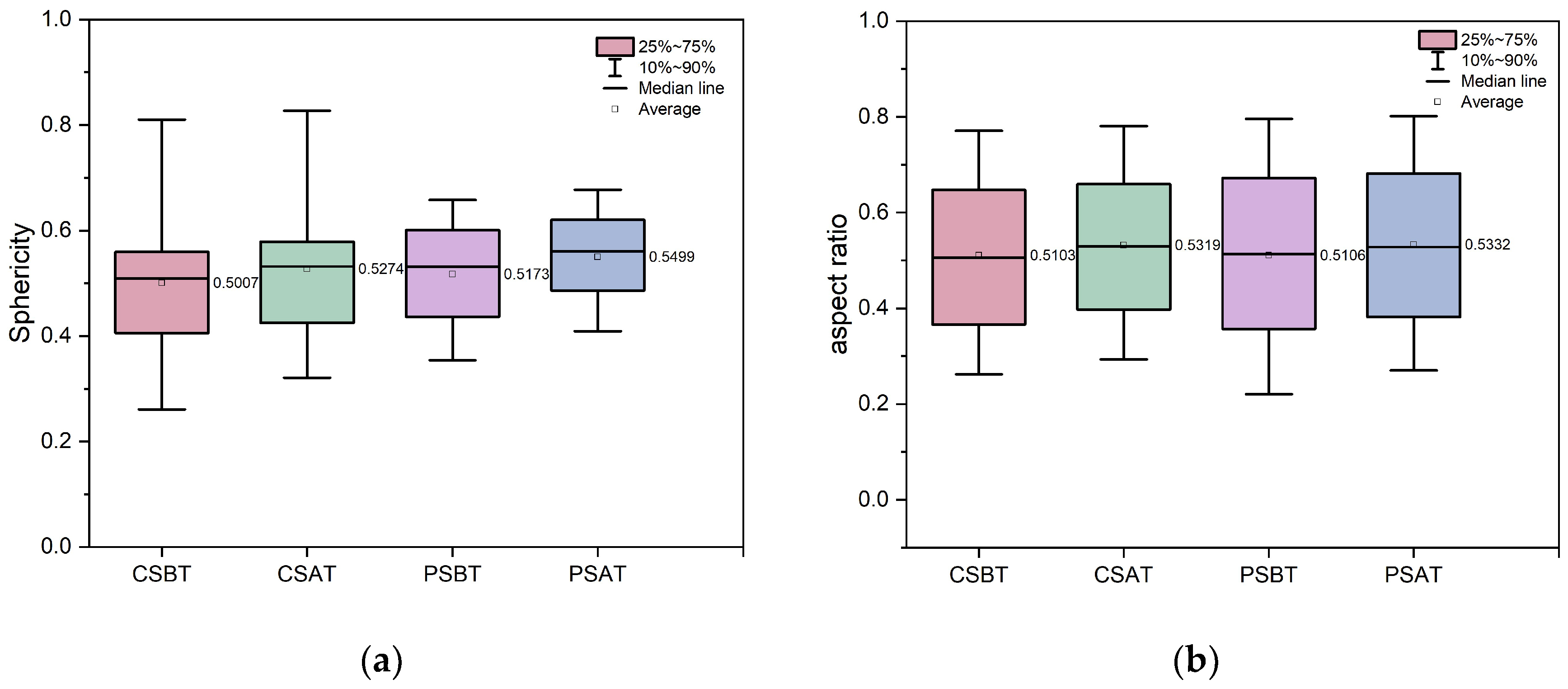
3.2. Particle Morphology Evolution for Pure and Cemented Calcareous Sand

Figure 7 illustrates the evolution of particle morphology through sphericity (Figure 7a) and aspect ratio (Figure 7b) measurements for both pure and cemented calcareous sands before and after triaxial tests. The pure sand showed increases in the average sphericity from 0.5173 to 0.5499 and the aspect ratio from 0.5106 to 0.5332, while the cemented sand showed increases in sphericity from 0.5007 to 0.5274 and the aspect ratio from 0.5103 to 0.5319. The results indicate that particles become more rounded and tend toward a more spherical shape after loading. This observation aligns with previous research by Wei et al., who demonstrated that the morphology of calcareous sand particles evolves toward higher sphericity during one-dimensional consolidation tests [31]. In addition, Gao et al. found that calcareous sand particles undergo continuous grinding during creep tests, resulting in progressively smoother and more rounded surfaces [47]. Furthermore, the increase in sphericity and the aspect ratio was more significant in pure sand compared to cemented sand. This can be attributed to the presence of gypsum in cemented sand, which restricted particle displacement and rotation during the experiment, thereby reducing inter-particle friction. In contrast, pure sand, lacking such constraints, experienced more significant increases in both sphericity and the aspect ratio.

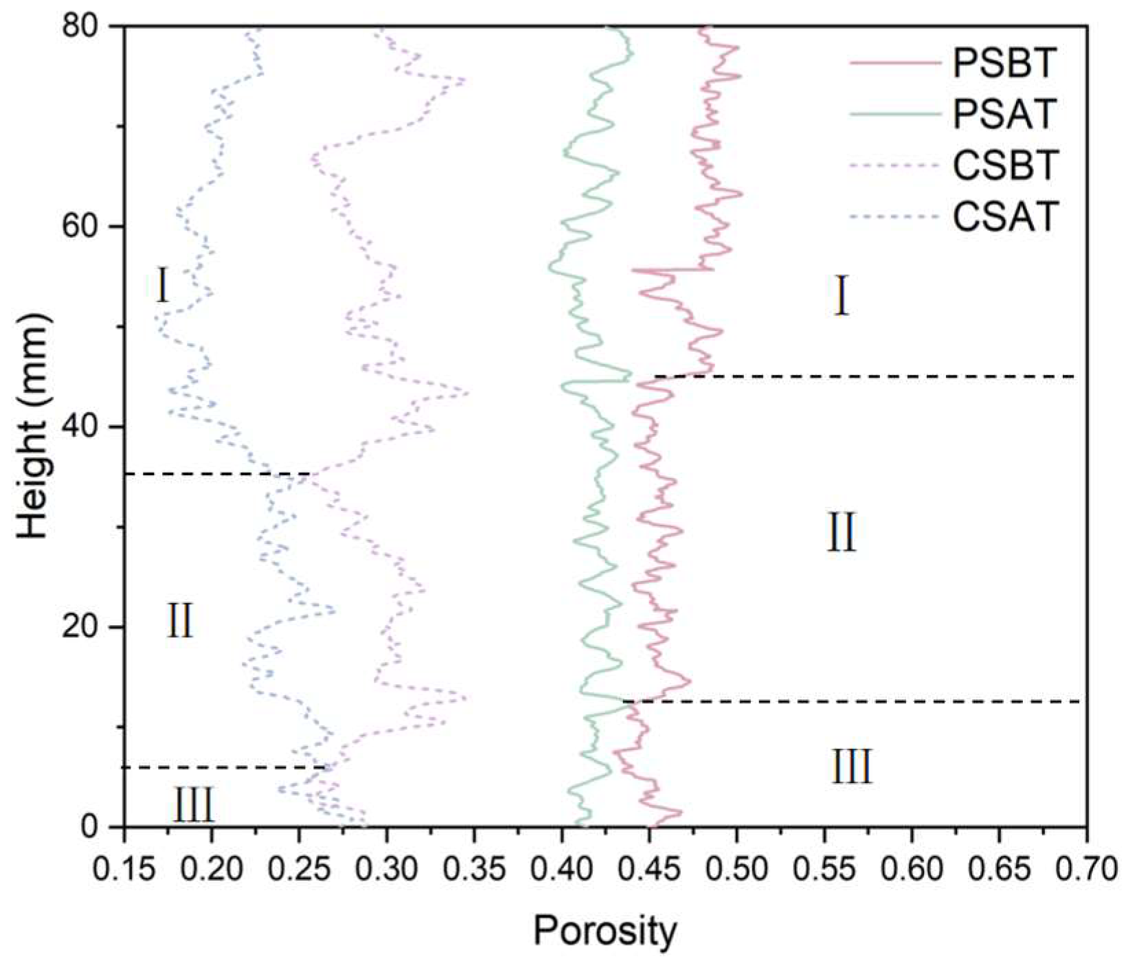
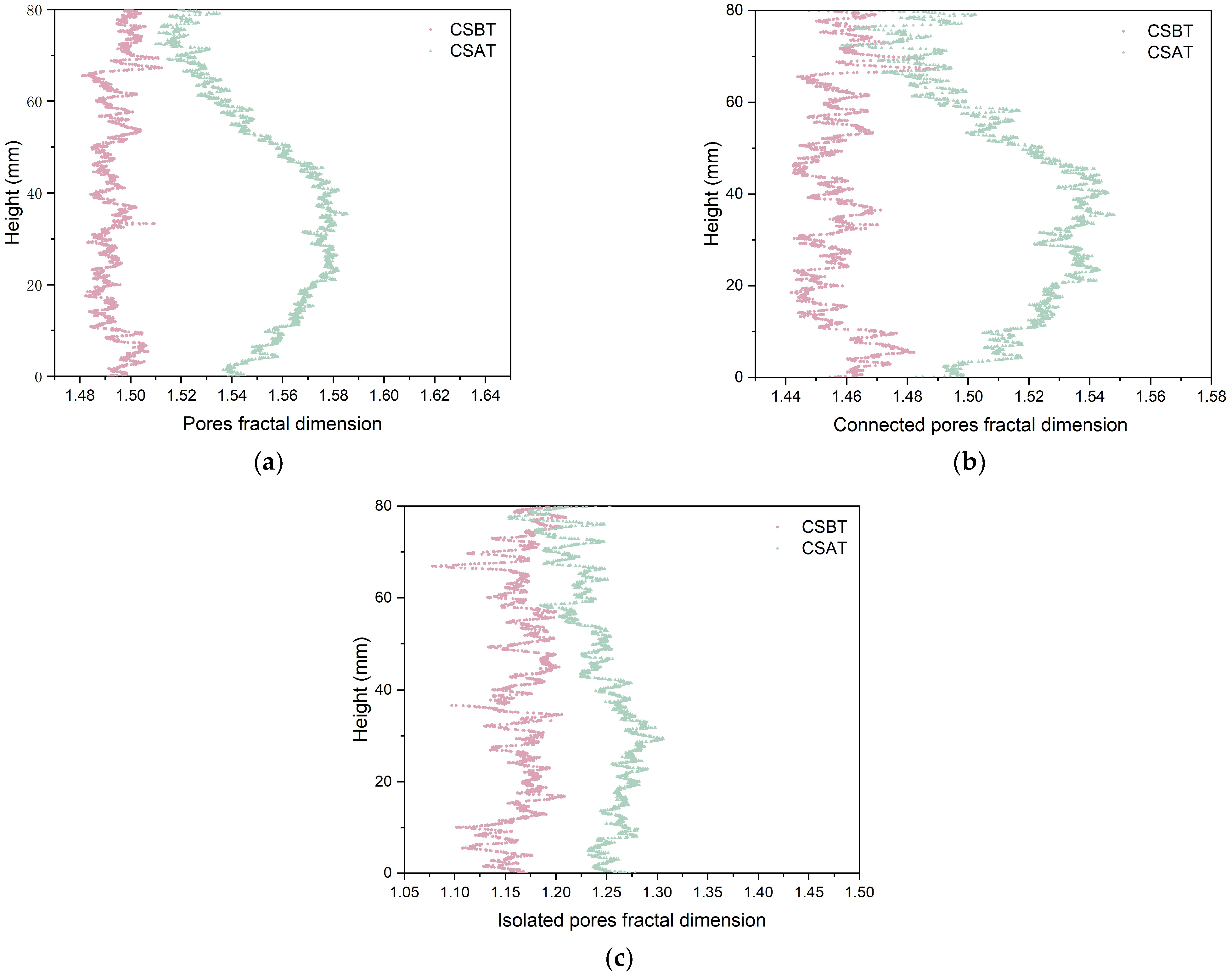
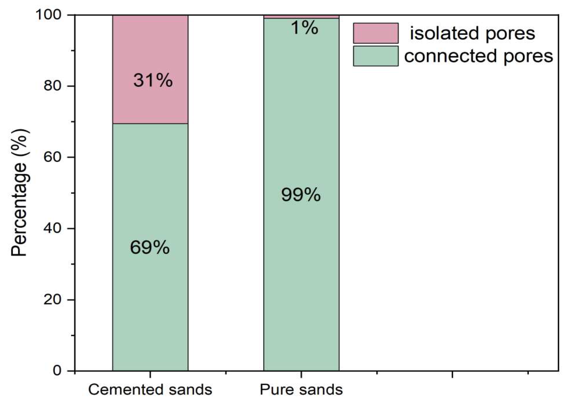
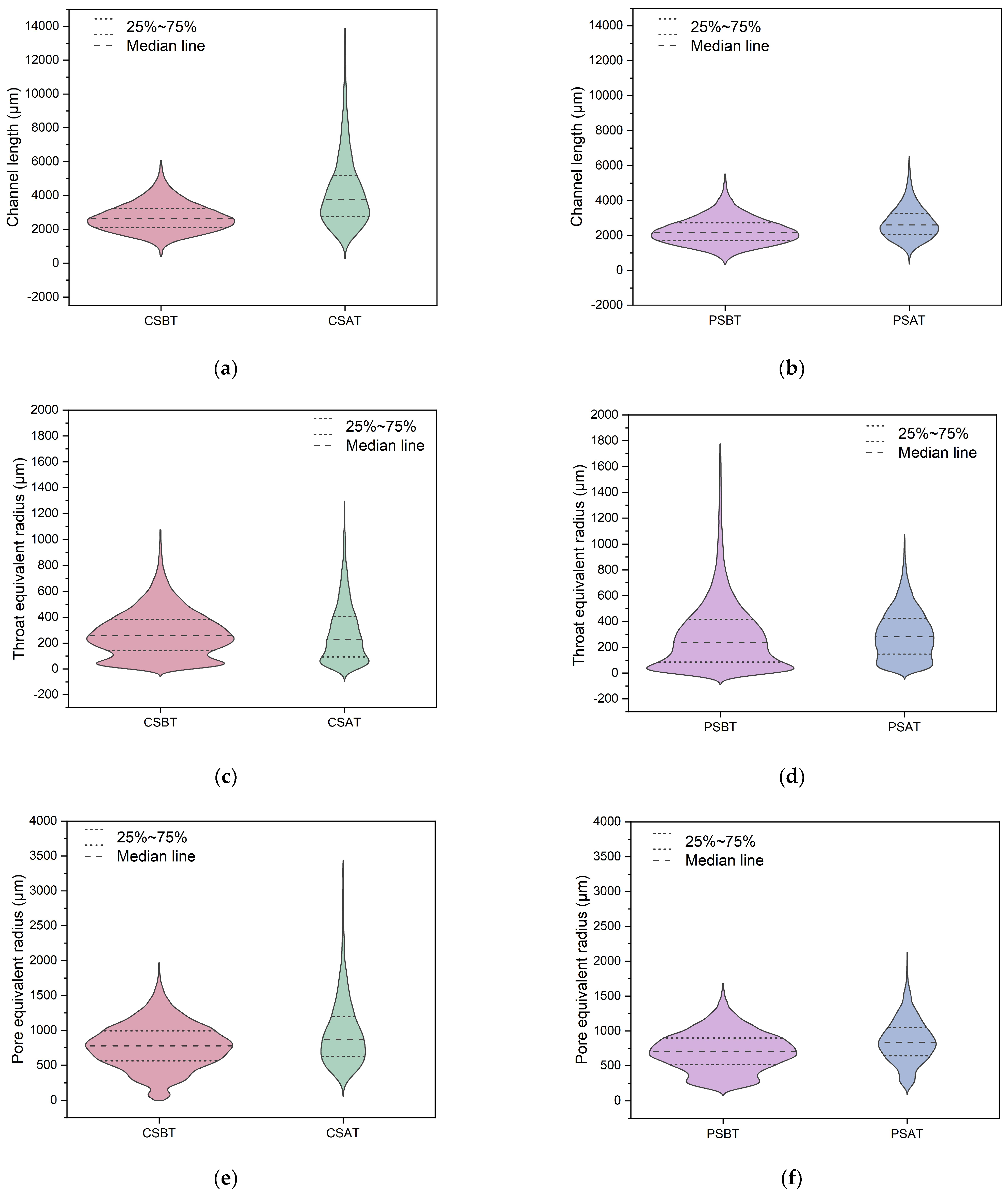
3.3. Comparison of Pore Morphology Evolution for Pure and Cemented Calcareous Sand

Figure 8 reveals distinct differences in spatial homogeneity between pure and gypsum-cemented calcareous sand specimens. Pure sand shows a better homogeneity, evidenced by smaller variations in porosity along the specimen height. In contrast, the heterogeneous distribution of porosity in cemented specimens can be attributed to differential air pressure preventing complete gypsum infiltration into non-connected pores. The vertical porosity distribution can be characterized in three distinct zones: Section I (top/loading end), Section II (middle part), and Section III (bottom part). Section I demonstrates the most significant porosity change after tests in both specimens, primarily due to predominant compressive forces causing particle breakage, rearrangement, and subsequent contraction behavior. Sections II and III are primarily subjected to shear forces, which induce particle sliding and outward dispersal, resulting in dilatancy. This dilatancy offsets some of the porosity reduction, leading to smaller changes in porosity compared to Section I. The overall porosity of the pure sand decreases from 0.47 before the test to 0.42 after the test, while the porosity of the cemented sand decreases from 0.30 before the test to 0.22, indicating a larger overall reduction in porosity for the cemented sand. This greater reduction is attributed to the capacity of cemented sand to carry higher effective stress under the same confining pressure. The resultant higher accumulated energy promotes intensified particle breakage and more efficient particle rearrangement, resulting in a more significant porosity reduction compared to the pure sand specimens.
Pore morphology in calcareous sand specimens could be effectively characterized by two parameters: sphericity and anisotropy. Figure 9 illustrates the distribution and mean values of the above parameters for both pure sand and cemented specimens before and after triaxial tests. The pore sphericity in pure sand specimens increased from 0.762 to 0.766 after testing, while cemented sand showed a similar trend with values rising from 0.7703 to 0.773 (Figure 9a). The analysis of pore anisotropy (Figure 9b) revealed decreasing trends in both specimen types following triaxial testing. Pure sand specimens showed a reduction from 0.8728 to 0.8644, while cemented specimens demonstrated a decrease from 0.8634 to 0.8498. These systematic changes in both parameters indicate an evolution toward more spherical and isotropic pore structures, attributed to the combined effects of particle breakage and pore compression during loading.
The fractal dimension is a quantitative indicator of the geometric complexity and self-similarity in particle and pore structures. In two-dimensional analysis, this parameter ranges from 1 to 2, where a value of 1 represents regular geometric features such as straight lines or circles, while values approaching 2 indicate increasingly complex and irregular morphologies. Higher fractal dimensions correlate with increased surface roughness and geometric complexity, making this parameter particularly valuable for characterizing the evolution of particle and pore morphologies during loading. Figure 10 and Figure 11 illustrate the evolution of pore fractal dimensions during triaxial tests. In cemented sand specimens, the mean fractal dimension increased from 1.49 to 1.55 for the overall pores, from 1.46 to 1.51 for the connected pores, and from 1.16 to 1.24 for the isolated pores. In contrast, there is no obvious change for pure sand specimens: the overall and connected pore dimensions increased slightly from 1.58 to 1.59, while the isolated pore dimensions remained constant at 1.07. The more pronounced variations in cemented sand specimens can be attributed to their capacity to carry higher effective stress, resulting in more particle breakage and more complex pore structures after the tests. The spatial analysis (Figure 10a,b and Figure 11a,b) illustrates that significant changes in pore fractal dimensions were concentrated in the lower middle section of the specimens. This region corresponds to the location of the shear band, where stress concentration leads to more particle breakage and pore structure transformations. The evolution of isolated pore fractal dimensions shows different patterns between cemented and pure sand specimens. While pure sand shows negligible changes in isolated pore fractal dimensions (Figure 11c), cemented sand demonstrates more pronounced variations (Figure 10c). This contrasting behavior can be attributed to two primary mechanisms: First, gypsum cementation transforms a portion of connected pores into isolated ones, consistent with observations by Ji et al., resulting in a higher initial proportion of isolated pores in cemented specimens [36]. Second, although isolated pores constitute a minor fraction of the total porosity (Figure 12), their increased presence in cemented specimens makes them more susceptible to morphological changes during loading. This greater susceptibility to deformation, coupled with their higher volumetric proportion, explains the more significant evolution of isolated pore fractal dimensions in cemented specimens compared to pure sand.

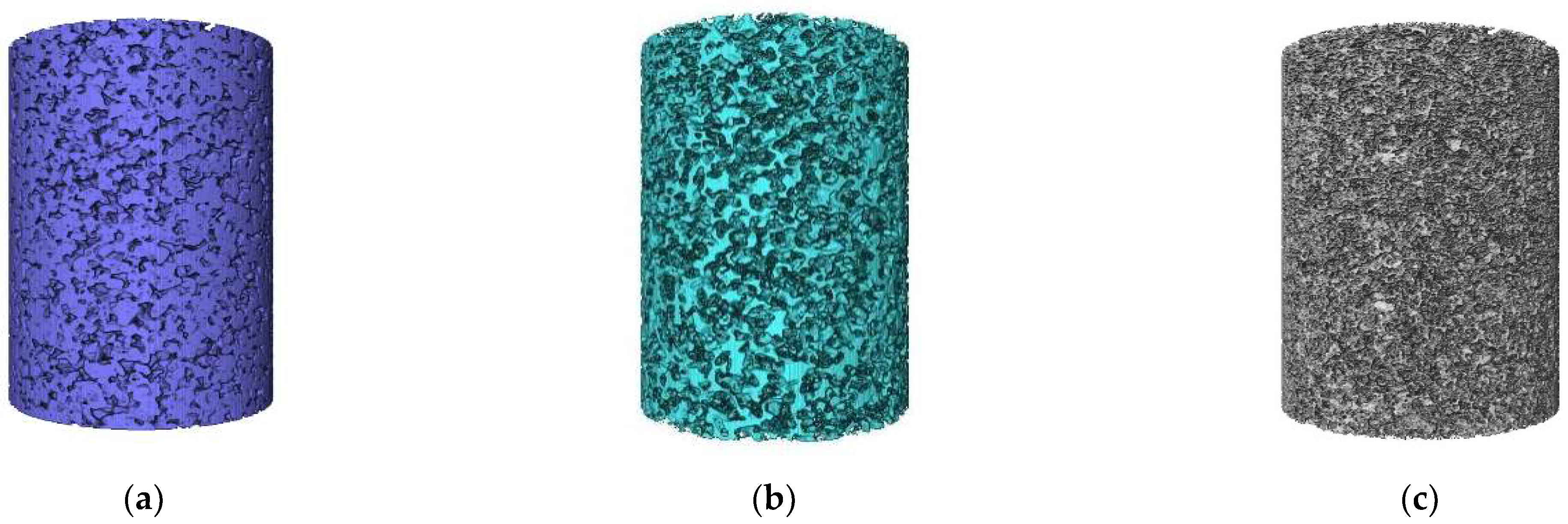
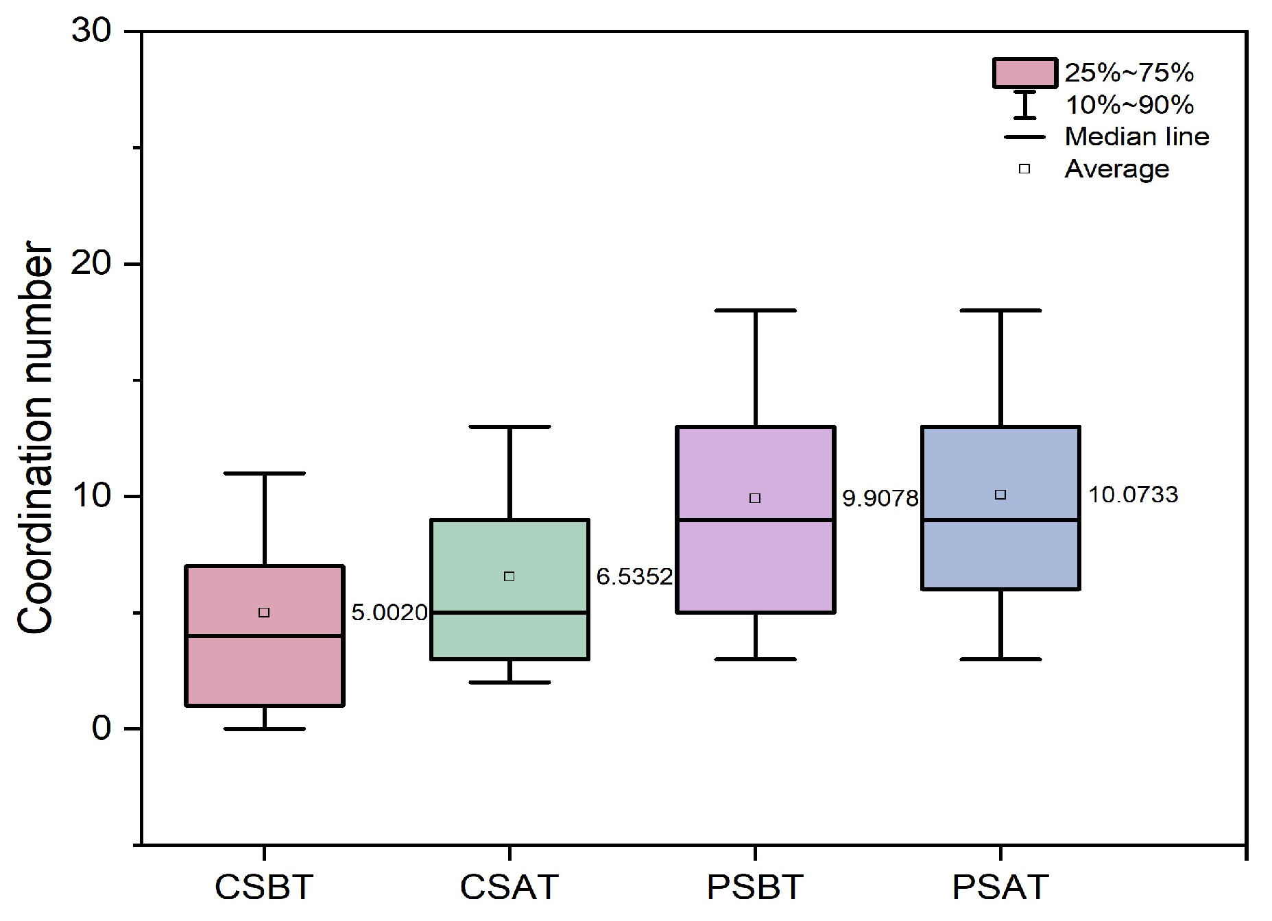
3.4. Microstructural Evolution for Pure and Cemented Calcareous Sand

According to Jaffar et al. [48], violin plots are useful for distribution analysis for soil microstructures. Figure 13 illustrates the evolution of the throat equivalent radius, channel length, and pore equivalent radius for pure and cemented calcareous sand after the triaxial test, respectively. For cemented calcareous sand specimens, results show a dramatic change in the microstructure after testing. The throat channel length distribution expands significantly from a concentrated range (1000–6000 μm) to a broader spectrum (500–14,000 μm), with the median value increasing by approximately 52% (Figure 13a). The throat equivalent radius shows a similar expansion trend, extending from 0–1000 μm to 0–1300 μm (Figure 13c), while the pore equivalent radius presents increased variability, with notable upper outliers reaching 3500 μm (Figure 13e). The changes mentioned above suggest extensive internal restructuring and potential micro-fracturing with the cemented specimens.
In contrast, pure sand specimens display remarkably different behavior characterized by smaller structural changes. The channel length distribution shows only a little expansion (approximately 15% increase in median value), maintaining a relatively stable range (Figure 13b). Similarly, both throat (Figure 13d) and pore equivalent radii (Figure 13f) demonstrate modest increases in their distributions, with the interquartile ranges remaining largely consistent before and after tests. This stability can be attributed to the absence of cement bonds, allowing individual sand particles to undergo rearrangement without a significant change to the overall pore network structure. The contrasting responses highlight the crucial role of cementation in determining the specimen’s microstructural stability under loading, with cemented sand exhibiting greater susceptibility to structural modification compared to the more stable granular framework of pure sand.
Figure 14 shows the equivalent pore network of pure and cemented calcareous sand extracted using the maximum ball method, where balls and tubes represent pores and throats, respectively. For pure calcareous sand specimens, the results indicate negligible microstructural changes after testing, with minimal variations in both the size and quantity of the balls and tubes (Figure 14a,b). In contrast, cemented calcareous sand specimens display a significant structural evolution. The results demonstrate a remarkable increase in the size of the balls and tubes, accompanied by a substantial decrease in their quantity (Figure 14c,d). Notably, pronounced changes in the pore network (balls and tubes) are concentrated in the middle to lower sections of the cemented calcareous sand specimens (Figure 14d), coinciding with the formation of shear bands in these regions from DVC analyses (Figure 15a). This correlation suggests that shear stress induces stress concentration near the shear bands, resulting in substantial modifications to the pores and throats in these regions. Figure 15b presents the displacement vector field observed in the central cross-section along the specimen height after the triaxial test. The analysis reveals the maximum displacement in the lower-middle region of the specimen, with an asymmetric distribution of displacement vectors around the central axis. Furthermore, the displacement magnitude gradually decreased radially outward from the central axis. A significant finding is the strong spatial correlation between shear band formation and microstructural evolution. DVC analysis reveals that maximum displacement concentration occurs in the lower-middle region of cemented specimens (Figure 15), coinciding precisely with areas showing the most pronounced changes in pore network characteristics (Figure 14d). This correlation provides direct evidence that shear-induced stress concentration drives localized microstructural transformation.
Figure 16 illustrates the distribution of pore coordination numbers, defined as the number of independent throats connected to an individual pore. The result reveals that cementation significantly reduced the pore coordination number from 9.9 in pure sand to 5 in the cemented specimen, suggesting a large number of pore–throat blockage by gypsum. The average value of pore coordination numbers for pure sand rarely changed (9.9 to 10) after the test, whereas cemented sand showed a remarkable increase (5 to 6.5). The difference in coordination number evolution can be attributed to the more pronounced shear effects, leading to improved pore network connectivity through potential cement bond breakage and subsequent throat formation.
The microstructural findings from this study have significant implications for large-scale geotechnical engineering applications, particularly in marine and coastal environments where calcareous sands are prevalent. The observed increases in the pore equivalent radius (52% increase in median values for cemented sand) and coordination number evolution (from 5 to 6.5 in cemented specimens) suggest enhanced hydraulic connectivity within the pore network post-loading. Based on the Kozeny–Carman equation, these microstructural changes indicate potential increases in permeability ranging from 15 to 25% for pure sand and 30–45% for cemented sand, respectively. This has critical implications for the foundation drainage design, seepage control, and long-term stability of marine structures. For South China Sea island and reef construction projects, the findings suggest that artificially cemented calcareous sand foundations may exhibit the following: (1) enhanced load-bearing capacity in the short term; (2) increased susceptibility to progressive failure under sustained loading; and (3) modified drainage characteristics that affect pore pressure dissipation. These factors are particularly relevant for runway construction, port facilities, and defensive structures where both strength and durability are critical design requirements.
While this study provides valuable insights into cemented calcareous sand behavior, several inherent limitations should be acknowledged. The gypsum-based artificial cementation employed may not fully represent natural cementation processes occurring in marine environments over geological timescales, as natural cementation typically involves calcium carbonate precipitation with different bonding mechanisms and spatial distributions compared to laboratory-prepared specimens [references on natural cementation]. Additionally, the 39.1 mm diameter specimens may not capture full-scale field behavior, particularly regarding shear band development and stress distribution patterns, while the investigation was limited to monotonic triaxial compression under 200 kPa confining pressure, which may not represent the complex stress paths and cyclic loading conditions encountered in real-world offshore applications. The CT resolution of 7.671 μm, while adequate for particle-scale analysis, may miss sub-particle features and micro-crack development that could influence long-term mechanical behavior, and the different initial relative densities between pure (45%) and cemented (70%) specimens, though representative of practical field conditions, may complicate the direct comparative interpretation of results. Furthermore, the relatively short experimental timeframe cannot capture the long-term cementation degradation effects or time-dependent microstructural evolution that would occur in actual marine environments, limiting the applicability of findings to long-term engineering design considerations.

4. Conclusions

In this study, triaxial consolidation-drained tests were conducted on pure and cemented calcareous sand specimens. X-ray computed tomography (CT) scanning was obtained before and after the triaxial tests to quantify the evolution of microstructures and particle characteristics. The key findings are summarized as follows:
  • Under identical confining pressures, cemented calcareous sand exhibited higher strength–stiffness characteristics with strain-softening behavior, in contrast to pure sand. A particle size distribution analysis revealed higher particle breakage in cemented sand (Br = 9.5%) compared to pure sand (Br = 8.7%). While gypsum cementation enhanced the sample strength, it promoted shear band development, leading to stress concentration and increased particle breakage.
  • Morphological analyses of particles showed greater increases in sphericity and the aspect ratio for pure calcareous sand compared to cemented specimens during triaxial tests. The presence of gypsum in cemented sand restricted sand particles’ movement and rotation, resulting in less pronounced morphological changes compared to pure calcareous sand.
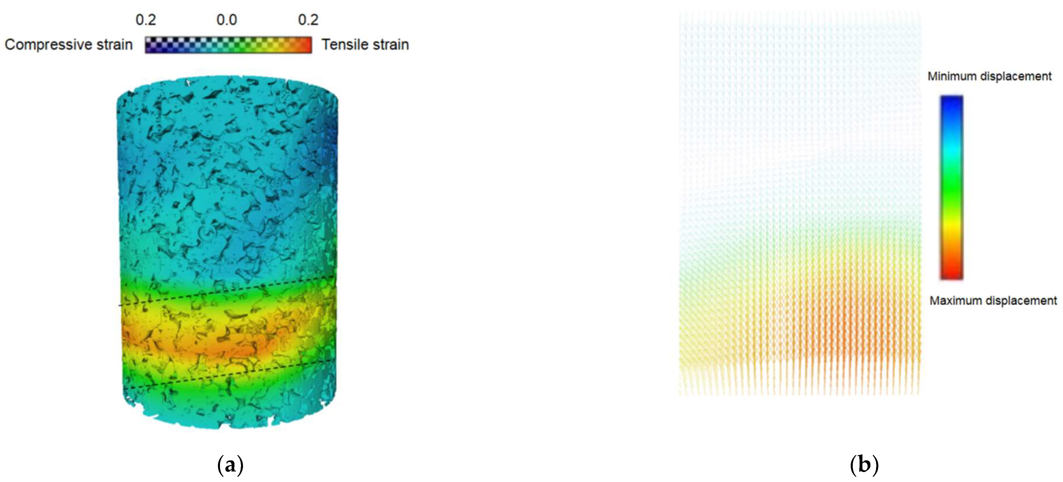
  • Pure calcareous sand exhibited a higher spatial homogeneity compared to the cemented specimens, evidenced by the lower porosity variation along specimen heights. The specimens were characterized by three distinct zones, with the top compression zone showing the most significant porosity reduction, while the middle and bottom zones experienced dilation under shear forces. In addition, cemented samples demonstrated more significant overall porosity reduction due to enhanced effective stress capacity. Pore morphology analyses indicated a slight increase in sphericity and the decreased anisotropy of pores for both specimen types. According to the change in pore fractal dimensions, a more pronounced structural evolution occurred in cemented sand (D from 1.49 to 1.55) than that in pure sand (D from 1.58 to 1.59), particularly within shear bands, suggesting more complex pore structure transformation mechanisms during loading in calcareous sand.
In general, both pure and cemented sand exhibited increases in their throat equivalent radius, channel length, and pore equivalent radius after triaxial tests. The magnitudes of these increases were slightly greater in cemented sand, particularly within the middle-to-lower parts where shear bands developed. These regions also demonstrated a significant reduction in pore and throat quantities, while pure sand showed only minor changes. Furthermore, the pore coordination number increased in both specimens, with cemented sand showing more remarkable changes compared to pure sand, suggesting enhanced pore network connectivity through potential cement bond degradation under loading conditions in this case.

Author Contributions

Methodology, W.W.; software, J.H.; validation, D.C. and Q.L.; investigation, W.W. and J.H.; writing—original draft preparation, J.H.; writing—review and editing, W.W.; supervision, B.Y. All authors have read and agreed to the published version of the manuscript.

Funding

This research was funded by National Natural Science Foundation of China, grant number 42377139 and Guangzhou Basic and Applied Basic Research Project, grant number SL2024A04J00481.

Data Availability Statement

The data presented in this study are available on request from the corresponding author.

Conflicts of Interest

Author Degao Chen is employed by the Guangdong Construction Engineering Quality & Safety Testing Head Station Co., Ltd. The remaining authors declare that the research was conducted in the absence of any commercial or financial relationships that could be construed as a potential conflict of interest.

References

  1. Fang, X.W.; Yang, Y.; Chen, Z.; Liu, H.L.; Xiao, Y.; Shen, C.N. Influence of Fiber Content and Length on Engineering Properties of MICP-Treated Coral Sand. Geomicrobiol. J. 2020, 37, 582–594. [Google Scholar] [CrossRef]
  2. Hu, F.H.; Fang, X.W.; Yao, Z.H.; Wu, H.R.; Shen, C.N.; Zhang, Y.T. Experiment and discrete element modeling of particle breakage in coral sand under triaxial compression conditions. Mar. Georesources Geotechnol. 2022, 41, 142–151. [Google Scholar] [CrossRef]
  3. El Aal, A.A.; Nabawy, B.S. Implications of increasing the ferruginous cement on the physical and mechanical properties of the Cambro-Ordovician Wajid Sandstone in southwest Saudi Arabia: Applications for construction purposes. Bull. Eng. Geol. Environ. 2019, 78, 817–836. [Google Scholar] [CrossRef]
  4. Nabawy, B.S.; Ibrahim, E.; Kahal, A.; Alfaifi, H.J.; Lashin, A.A. Impact of authigenic iron oxides, clay content and grain size on the aquifer quality properties of the Cambrian-Ordovician Wajid Sandstone, southwest Saudi Arabia. J. Afr. Earth Sci. 2020, 172, 104000. [Google Scholar] [CrossRef]
  5. Wei, H.; Li, X.; Zhang, S.; Zhao, T.; Yin, M.; Meng, Q. Influence of Particle Breakage on Drained Shear Strength of Calcareous Sands. Int. J. Geomech. 2021, 21, 04021118. [Google Scholar] [CrossRef]
  6. Coop, M.R.; Atkinson, J.H. The mechanics of cemented carbonate sands. Géotechnique 1993, 43, 53–67. [Google Scholar] [CrossRef]
  7. Ismail, M.A.; Joer, H.A.; Randolph, M.F.; Meritt, A. Cementation of porous materials using calcite. Géotechnique 2002, 52, 313–324. [Google Scholar] [CrossRef]
  8. Liu, L.; Liu, H.; Stuedlein, A.W.; Evans, T.M.; Xiao, Y. Strength, stiffness, and microstructure characteristics of biocemented calcareous sand. Can. Geotech. J. 2019, 56, 1502–1513. [Google Scholar] [CrossRef]
  9. Wang, W.; Li, J.; Hu, J. Triaxial Mechanical Properties and Micromechanism of Calcareous Sand Modified by Nanoclay and Cement. Geofluids 2021, 9, 6639602. [Google Scholar] [CrossRef]
  10. Xu, D.; Zhang, Z.; Qin, Y.; Yang, Y. Effect of particle size on the failure behavior of cemented coral sand under impact loading. Soil Dyn. Earthq. Eng. 2021, 149, 106884. [Google Scholar] [CrossRef]
  11. Ismail Mostafa, A.; Joer, H.A.; Sim, W.H.; Randolph, M.F. Effect of Cement Type on Shear Behavior of Cemented Calcareous Soil. J. Geotech. Geoenviron. Eng. 2002, 128, 520–529. [Google Scholar] [CrossRef]
  12. Consoli, N.C.; Fonseca, A.V.D.; Cruz, R.C.; Heineck, K.S. Fundamental Parameters for the Stiffness and Strength Control of Artificially Cemented Sand. J. Geotech. Geoenviron. Eng. 2009, 135, 1347–1353. [Google Scholar] [CrossRef]
  13. Consoli, N.C.; Moraes, R.; Festugato, L. Parameters Controlling Tensile and Compressive Strength of Fiber-Reinforced Cemented Soil. J. Mater. Civ. Eng. 2013, 25, 1568–1573. [Google Scholar] [CrossRef]
  14. Consoli, N.C.; Rosa, A.D.; Corte, M.B.; Lopes, L.S.; Consoli, B.S. Porosity-Cement Ratio Controlling Strength of Artificially Cemented Clays. J. Mater. Civ. Eng. 2011, 23, 1249–1254. [Google Scholar] [CrossRef]
  15. Sharma, M.S.R.; Baxter, C.D.P.; Moran, K.; Varizi, H.; Narayanasamy, R. Strength of Weakly Cemented Sands from Drained Multistage Triaxial Tests. J. Geotech. Geoenviron. Eng. 2011, 137, 1202–1210. [Google Scholar] [CrossRef]
  16. Li, B.; Chen, Y. Mechanical Behavior of Cemented Sand Considering Particle Breakage. J. Southwest Jiaotong Univ. 2016, 51, 729–735. (In Chinese) [Google Scholar]
  17. Liu, X.; Dong, C. Research on Mechanical Characteristics of the Cemented Sandstone Based on 3Dimensional PFC Numerical Model. J. Chongqing Univ. 2013, 36, 37–44. (In Chinese) [Google Scholar]
  18. Coop, M.R. The mechanics of uncemented carbonate sands. Géotechnique 1990, 40, 607–626. [Google Scholar] [CrossRef]
  19. Carrera, A.; Coop, M.; Lancellotta, R. Influence of grading on the mechanical behaviour of Stava tailings. Géotechnique 2011, 61, 935–946. [Google Scholar] [CrossRef]
  20. Xiao, Y.; Liu, H. Elastoplastic Constitutive Model for Rockfill Materials Considering Particle Breakage. Int. J. Geomech. 2017, 17, 04016041. [Google Scholar] [CrossRef]
  21. Yu, F.; Su, L. Particle breakage and the mobilized drained shear strengths of sand. J. Mt. Sci. 2016, 13, 1481–1488. [Google Scholar] [CrossRef]
  22. Wu, Y.; Li, N.; Wang, X.; Cui, J.; Chen, Y.; Wu, Y.; Yamamoto, H. Experimental investigation on mechanical behavior and particle crushing of calcareous sand retrieved from South China Sea. Eng. Geol. 2021, 280, 105932. [Google Scholar] [CrossRef]
  23. Yu, F. Particle breakage in triaxial shear of a coral sand. Soils Found. 2018, 58, 866–880. [Google Scholar] [CrossRef]
  24. Alikarami, R.; Ando, E.; Gkiousas-Kapnisis, M.; Torabi, A.; Viggiani, G. Strain localisation and grain breakage in sand under shearing at high mean stress: Insights from in situ X-ray tomography. Acta Geotech. 2015, 10, 15–30. [Google Scholar] [CrossRef]
  25. Karatza, Z.; And, E.; Papanicolopulos, S.-A.; Ooi, J.Y.; Viggiani, G. Evolution of deformation and breakage in sand studied using X-ray tomography. Geotechnique 2017, 68, 107–117. [Google Scholar] [CrossRef]
  26. Zhu, S.; Gong, L.; Hu, Z.; Xu, Y.; He, Y.; Long, Y. Single-Particle Crushing Test of Coated Calcareous Sand Based on MICP. Materials 2024, 17, 4690. [Google Scholar] [CrossRef]
  27. Wang, W.; Coop, M.R. An investigation of breakage behaviour of single sand particles using a high-speed microscope camera. Géotechnique 2016, 66, 984–998. [Google Scholar] [CrossRef]
  28. Zhao, B.; Wang, J.; Coop, M.R.; Viggiani, G.; Jiang, M. An investigation of single sand particle fracture using X-ray micro-tomography. Géotechnique 2015, 65, 625–641. [Google Scholar] [CrossRef]
  29. Zhao, B.; Wang, J. 3D quantitative shape analysis on form, roundness, and compactness with μCT. Powder Technol. 2016, 291, 262–275. [Google Scholar] [CrossRef]
  30. Zhu, F.; Zhao, J. Interplays between particle shape and particle breakage in confined continuous crushing of granular media. Powder Technol. 2021, 378, 455–467. [Google Scholar] [CrossRef]
  31. Wei, H.; Liu, H.; Zhao, T.; Zhang, S.; Ma, L.; Yin, M.; Meng, Q. Particle breakage and morphology changes of calcareous sands under one-dimensional compression loading. Mar. Geophys. Res. 2022, 43, 45. [Google Scholar] [CrossRef]
  32. Zhang, X.; Hu, W.; Scaringi, G.; Baudet, B.A.; Han, W. Particle shape factors and fractal dimension after large shear strains in carbonate sand. Géotech. Lett. 2018, 8, 73–79. [Google Scholar] [CrossRef]
  33. Fonseca, J.; O’Sullivan, C.; Coop, M.R.; Lee, P.D. Non-invasive characterization of particle morphology of natural sands. Soils Found. 2012, 52, 712–722. [Google Scholar] [CrossRef]
  34. Shi, F.; Li, T.; Wang, W.; Liu, R.; Liu, X.; Tian, H.; Liu, N. Research on the Effect of Desert Sand on Pore Structure of Fiber Reinforced Mortar Based on X-CT Technology. Materials 2021, 14, 5572. [Google Scholar] [CrossRef]
  35. Yuan, H.; Zhang, Z.; Huang, X.; Li, Y. Comparing, slurry infiltration characteristics between calcareous and silica sands based on slurry infiltration column tests and CT scanning. Tunn. Undergr. Space Technol. 2024, 152, 105919. [Google Scholar] [CrossRef]
  36. Ji, Y.; Zhou, J.; Xie, L.; Shen, L.; Zheng, Y.; Ma, S. Quantitative microstructural characterization and seepage visualization of biocemented sand. Comput. Geotech. 2024, 174, 106594. [Google Scholar] [CrossRef]
  37. Kootahi, K.; Leung, A.K.; Jiang, Z.; Liu, J.; Qi, R.; Lourenço, S.D.N.; Lai, Z.; Gao, Z. Evaluation of the Methods of Particle Morphology Characterization: CT Scanning, Digital Imaging and Light Microscopy. Comput. Geotech. 2024, 174, 106648. [Google Scholar] [CrossRef]
  38. Qin, Q.; Wu, K.; Meng, Q.; Gan, M.; Yi, P. Investigation of mechanical characterization and damage evolution of coral reef sand concrete using in-situ CT and digital volume correlation techniques. J. Build. Eng. 2024, 96, 110480. [Google Scholar] [CrossRef]
  39. Cheng, Z.; Wang, J. An investigation of the breakage behaviour of a pre-crushed carbonate sand under shear using X-ray micro-tomography. Eng. Geol. 2021, 293, 106286. [Google Scholar] [CrossRef]
  40. Charalampidou, E.M.; Hall, S.A.; Stanchits, S.; Lewis, H.; Viggiani, G. Characterization of shear and compaction bands in a porous sandstone deformed under triaxial compression. Tectonophysics 2011, 503, 8–17. [Google Scholar] [CrossRef]
  41. Wadell, H. Volume, Shape, and Roundness of Rock Particles. J. Geol. 1932, 40, 443–451. [Google Scholar] [CrossRef]
  42. Fernlund, J.M.R. Image analysis method for determining 3-D shape of coarse aggregate. Cem. Concr. Res. 2005, 35, 1629–1637. [Google Scholar] [CrossRef]
  43. Hardin Bobby, O. Crushing of Soil Particles. J. Geotech. Eng. 1985, 111, 1177–1192. [Google Scholar] [CrossRef]
  44. Smith, T.S.; Bay, B.K.; Rashid, M.M. Digital volume correlation including rotational degrees of freedom during minimization. Exp. Mech. 2002, 42, 272–278. [Google Scholar] [CrossRef]
  45. Madi, K.; Tozzi, G.; Zhang, Q.H.; Tong, J.; Cossey, A.; Au, A.; Hollis, D.; Hild, F. Computation of full-field displacements in a scaffold implant using digital volume correlation and finite element analysis. Med. Eng. Phys. 2013, 35, 1298–1312. [Google Scholar] [CrossRef]
  46. Xu, Z.; Lin, M.; Ji, L.; Jiang, W.; Cao, G.; Xu, L. Multiscale pore-fracture hybrid pore network modeling for drainage in tight carbonate. Adv. Water Resour. 2023, 174, 104420. [Google Scholar] [CrossRef]
  47. Gao, Y.; Shi, T.; Yuan, Q.; Sun, K. The creep characteristics and related evolution of particle morphology for calcareous sand. Powder Technol. 2024, 431, 119077. [Google Scholar] [CrossRef]
  48. Jaffar, S.T.A.; Chen, X.; Bao, X.; Raja, M.N.A.; Abdoun, T.; El-Sekelly, W. Data-driven intelligent modeling of unconfined compressive strength of heavy metal-contaminated soil. J. Rock Mech. Geotech. Eng. 2025, 17, 1801–1815. [Google Scholar] [CrossRef]
Figure 1. Calcareous sands used in this study: (a) macroscopic view; (b) SEM images.
Buildings 15 02041 g001
Figure 2. Phoenix v|tome|x m industrial CT system. (a) External images of the device, (b) The sample is located inside the device (before the test), (c) The sample is located inside the device (after the test).
Buildings 15 02041 g002
Figure 3. Three-dimensional reconstructions of cemented calcareous sand with gypsum: (a) calcareous sand; (b) pore; (c) gypsum.
Buildings 15 02041 g003
Figure 4. A subset-based algorithm is used to initialize a more robust FE-based global DVC technique.
Buildings 15 02041 g004
Figure 5. Stress–strain relationships of pure sand and cemented sand.
Buildings 15 02041 g005
Figure 6. Particle grading curves of pure and cemented sand after triaxial tests.
Buildings 15 02041 g006
Figure 7. Statistical analysis of particle morphology for pure and cemented sand before and after tests: (a) sphericity; (b) aspect ratio. (The “25%–75%” in the icon applies to all boxes).
Buildings 15 02041 g007
Figure 8. Porosity variations with height before and after testing for pure sand and cemented sand.
Buildings 15 02041 g008
Figure 9. Statistical analysis of characteristics in pores before and after testing for pure sand and cemented sand: (a) sphericity; (b) anisotropy. (The “25%–75%” in the icon applies to all boxes).
Buildings 15 02041 g009
Figure 10. Fractal dimensions of different types of pores for cemented sand before and after tests: (a) overall pores; (b) connected pores; (c) isolated pores.
Buildings 15 02041 g010
Figure 11. Fractal dimensions of different types of pores for pure sand before and after tests: (a) overall pores; (b) connected pores; (c) isolated pores.
Buildings 15 02041 g011
Figure 12. Comparison of the proportion of isolated pores and connected pores in cemented and pure sands.
Buildings 15 02041 g012
Figure 13. Violin plots of the evolution of pore networks for calcareous sand after tests: (a) channel length for cemented sand; (b) channel length for pure sand; (c) throat equivalent radius for cemented sand; (d) throat equivalent radius for pure sand; (e) pore equivalent radius for cemented sand; (f) pore equivalent radius for pure sand.
Buildings 15 02041 g013
Figure 14. (a) The PNM of pure sand before tests. (b) The PNM of pure sand after tests. (c) The PNM of cemented sand before tests. (d) The PNM of cemented sand after tests.
Buildings 15 02041 g014
Figure 15. (a) Localized strain model for cemented sand. (b) The displacement variation along the height direction at the central position of the cemented sand specimen.
Buildings 15 02041 g015
Figure 16. The statistical analysis of pore coordination numbers before and after testing for pure and cemented sand. (The “25%–75%” in the icon applies to all boxes).
Buildings 15 02041 g016
Table 1. Basic physical parameters of calcareous sand.
Size (mm)ρdmin/(g/cm3)ρdmax/(g/cm3)Gseminemax
1.18~2.360.811.332.731.062.41
Disclaimer/Publisher’s Note: The statements, opinions and data contained in all publications are solely those of the individual author(s) and contributor(s) and not of MDPI and/or the editor(s). MDPI and/or the editor(s) disclaim responsibility for any injury to people or property resulting from any ideas, methods, instructions or products referred to in the content.

