Article

Development and Performance Evaluation of a Novel Disc-Buckle Steel Scaffold Joint

1
Guangzhou Research Institute of Construction Industry Co., Ltd., Guangzhou 510663, China
2
Guangzhou Construction Engineering Co., Ltd., Guangzhou 510030, China
3
School of Civil and Transportation Engineering, Guangdong University of Technology, Guangzhou 510006, China
4
Guangzhou Construction Industry Development Co., Ltd., Guangzhou 510663, China
*
Author to whom correspondence should be addressed.
Buildings 2025, 15(12), 2034; https://doi.org/10.3390/buildings15122034
Submission received: 16 February 2025 / Revised: 24 May 2025 / Accepted: 9 June 2025 / Published: 13 June 2025
(This article belongs to the Section Building Structures)

Abstract

:
The disc-buckle scaffold system demonstrates significant advantages in prefabricated construction applications, particularly in terms of installation efficiency, load-bearing capacity, and standardization. Guangzhou Construction Group Co., Ltd., a leading enterprise in promoting prefabricated building development in Guangdong Province, China, has collaborated with the Guangdong University of Technology to develop an innovative disc-buckle scaffold system. The main difference between different scaffolds lies in the connection part of the joint. The mechanical behavior of scaffold joint plays a critical role in determining the structural integrity of the entire scaffolding system. So, the novel disc-buckle scaffold proposed in this paper is mainly new in the joint. Finite element simulation based on the test results is employed to study the performance of the novel scaffold joint in this paper. The results show that the newly developed scaffold joint exhibits superior mechanical performance, characterized by a bending stiffness of 34.5 kN·m/rad. The joint demonstrates maximum tensile and compressive bearing capacities of approximately 108 kN and 70 kN in the transverse direction, respectively. Furthermore, the joint’s maximum shear bearing capacity exceeds 180 kN, surpassing the buckling critical force of the vertical steel pipe and satisfying all strength requirements. The scaffold joint exhibits robust hysteresis characteristics, and the wedge-shaped connection mechanism maintains consistent stiffness and load-bearing symmetry under both positive and negative bending moments. The proposed disc-buckle steel scaffold joint features a minimal number of components, achieving an optimal balance between structural performance and economic efficiency.

1. Introduction

With the rapid development of socio-economic infrastructure, steel pipe support systems have progressively replaced traditional wooden support frameworks in large-scale construction projects [1]. Contemporary steel pipe support systems predominantly employ several scaffolding variants, including portal scaffolding, coupler scaffolding, wheel-buckle scaffolding, bowl-buckle scaffolding, and disc-buckle scaffolding. Among these, the disc-buckle scaffolding system demonstrates exceptional versatility, allowing for flexible configuration into various functional construction structures such as single-row scaffolds, double-row scaffolds, and support frames, tailored to specific project requirements. This adaptability renders it suitable for diverse construction applications, including but not limited to elevated bridge construction, tunnel engineering projects, industrial and civil building construction, storage shelf systems, and underground engineering works [2,3,4].
In recent years, the prefabricated building sector has experienced significant growth, driven by advancements in construction technology and industrialization. The inherent characteristics of disc-buckle scaffolding systems, particularly their modularity and structural efficiency, offer substantial advantages for prefabricated construction applications, thereby creating new development opportunities within the industry [5]. As a leading enterprise in promoting prefabricated construction development in Guangzhou, Guangdong Province, China, Guangzhou Construction Group Co., Ltd., has prioritized the development of an innovative disc-buckle scaffolding system with independent intellectual property rights. In collaboration with the Guangdong University of Technology, the research team has developed and optimized a novel disc-buckle scaffolding system through comprehensive experimental investigations and finite element analysis. This systematic approach has enabled the evaluation and enhancement of the system’s structural performance, ensuring its suitability for modern prefabricated construction applications.

2. An Innovative Disc-Buckle Scaffolding

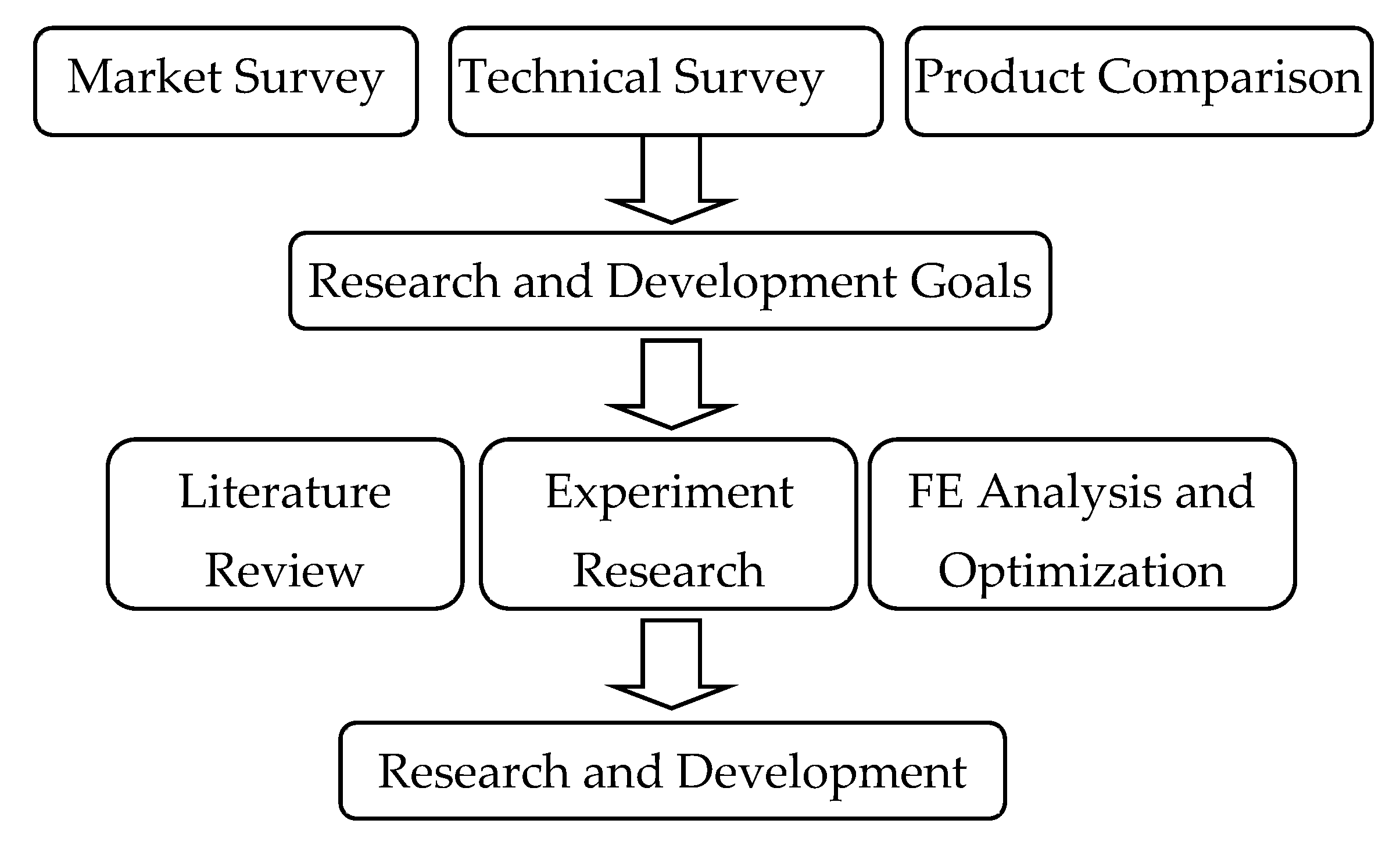
2.1. Research and Development Strategy

This study outlines a systematic research and development strategy for an innovative scaffolding system that integrates the advantages of existing products while addressing their limitations. As depicted in Figure 1, the strengths and weaknesses of various scaffolding systems are comprehensively analyzed through extensive market survey and literature review. Building on these findings and aligning with the company’s operational capabilities and practical requirements, a novel disc-buckle scaffolding system is proposed, offering enhanced performance and cost-effectiveness. The mechanical properties of the proposed disc-buckle scaffolding are rigorously evaluated through experimental testing and further optimized using finite element analysis.

2.2. Research and Development Goals

Based on comprehensive market surveys, technical analyses, and comparative product evaluations, this study identifies the essential characteristics of high-performance scaffolding systems. An optimal scaffold product should exhibit a simple structural design, minimal accessory components, ease of assembly and disassembly, high standardization, superior load-bearing capacity, excellent stability, and cost-effectiveness. Among existing systems, the disc-buckle scaffold demonstrates superior comprehensive performance, particularly in terms of load-bearing capacity, installation efficiency, structural flexibility, and economic viability, making it a highly competitive solution. Consequently, the development of the proposed novel disc-buckle scaffold in this paper prioritizes the fulfillment of three critical performance indicators: safety, economic efficiency, and applicability. These criteria ensure that the new system meets the evolving demands of modern construction practices while maintaining a balance between performance and cost.

2.3. The Configuration of the Novel Disc-Buckle Scaffolding

The main difference between different types of scaffolds lies in the connection part of the joint as the novel disc-buckle scaffold proposed in this paper is mainly new in the joint. The proposed joint configuration is illustrated in Figure 2, with its sequential assembly procedure detailed in Figure 3. As depicted in Figure 2, the novel disc-buckle scaffold joint contains a fixed disc, a stopper disc, and a stopper spot. The fixed disc features teeth for secure engagement, while the stopper disc is equipped with three striking notches that allow it to be rotated by hammering. As shown in Figure 2a, the stopper spot is an iron block welded to the vertical pipe. After correct installation, the stopper spot can limit the stopper disc. The installation process eliminates ancillary accessories, requiring only hammer operation for component engagement/disengagement. The assembly procedure comprises four sequential operations:
  • Insertion and Compression: Initially, insert the horizontal pipe’s end connector into the fixed disc and let it attach tightly to the fixed disc by applying compressive force on it;
  • Rotational Alignment: Subsequently, rotate the stopper disc to align the stopper spot by hammering the notches on the stopper disc, ensuring mechanical interlock through the stopper spot;
  • Vertical Engagement: Third, engage the stopper disc with the fixed disc;
  • Impact Fixation: Finally, secure the assembly by a hammer. The stopper disc is tightly attached to the fixed disc by hammering the striking mouth on the stopper disc.
Traditional disc-buckle scaffold system employs locking pins as the primary fastening mechanism to secure horizontal and diagonal members at structural joints. However, field applications reveal that these pins are susceptible to displacement, wear, and potential loss. The coupler components (adapter plug and pin) in wheel-type buckle scaffolds and disc-buckle scaffolds adopt a tapered configuration characterized by a widened upper profile and narrowed lower geometry. This wedge-shaped design effectively accommodates minor horizontal geometric deviations arising from positioning tolerances or upright member imperfections during scaffold erection, thereby enhancing installation success rates and operational efficiency through error compensation. The novel disc-buckle scaffold joint, which has the structural advantages of wheeled and bowl-shaped scaffolds, is easier to install and has a better load-bearing capacity than traditional scaffolds, preventing the problem of easy loss and wear of components such as locking pins.

3. Finite Element Modeling of the Novel Scaffold Joint

3.1. Finite Element Model

The mechanical behavior of scaffold joints plays a critical role in determining the structural integrity of the entire scaffolding system. Consequently, comprehensive investigation into the joint performances becomes imperative. This study employs finite element method simulations to analyze the rotational stiffness and ultimate bearing capacity of the novel disc-buckle scaffold joint based on experimental validation through full-scale laboratory tests.
A three-dimensional finite element model of the scaffold joint was developed in SIMULIA Abaqus 2021‌ finite element software The finite element (FE) model utilizes eight-node linear brick elements with reduced integration (C3D8R) for spatial discretization. Contact interactions between joint components were simulated through surface-to-surface algorithms, with normal behavior governed by hard contact formulation and tangential response characterized by the penalty friction method (coefficient μ = 0.2). Adaptive mesh is adopted. Material constitutive relationships were established based on the Chinese steel grade specifications, employing a combined hardening model to account for cyclic plasticity effects. Material performance tests were conducted according to Chinese standards: GB/T 228.1-2021 Metallic Materials—Tensile Testing—Part 1: Method of Test at Room Temperature [6]‌. Key material parameters, including yield strength, elastic modulus, and Poisson’s ratio, are presented in Table 1. Both the horizontal and vertical bars are made of standard scaffolding pipes specified in JGT 503-2016 Socket and Spigot Disc Lock Steel Tube Scaffolding Components [7], with dimensions of φ 48.3 × 3.2.

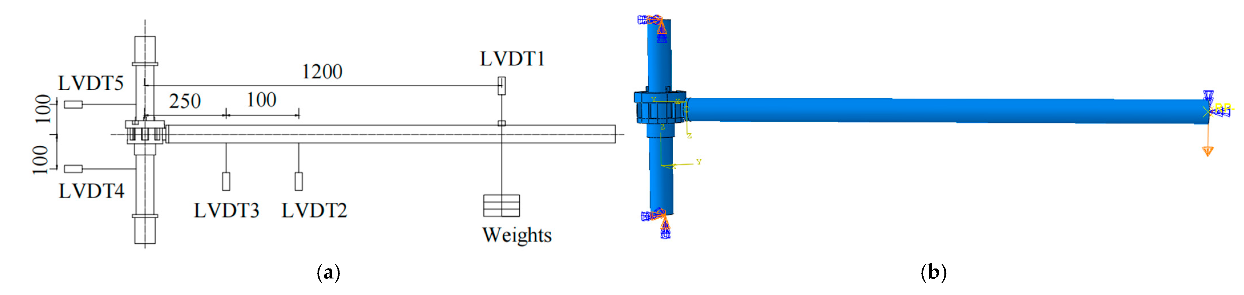
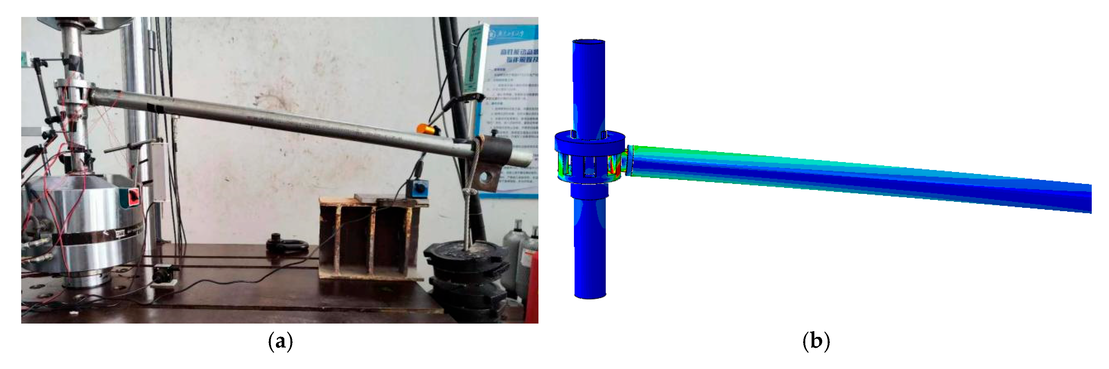
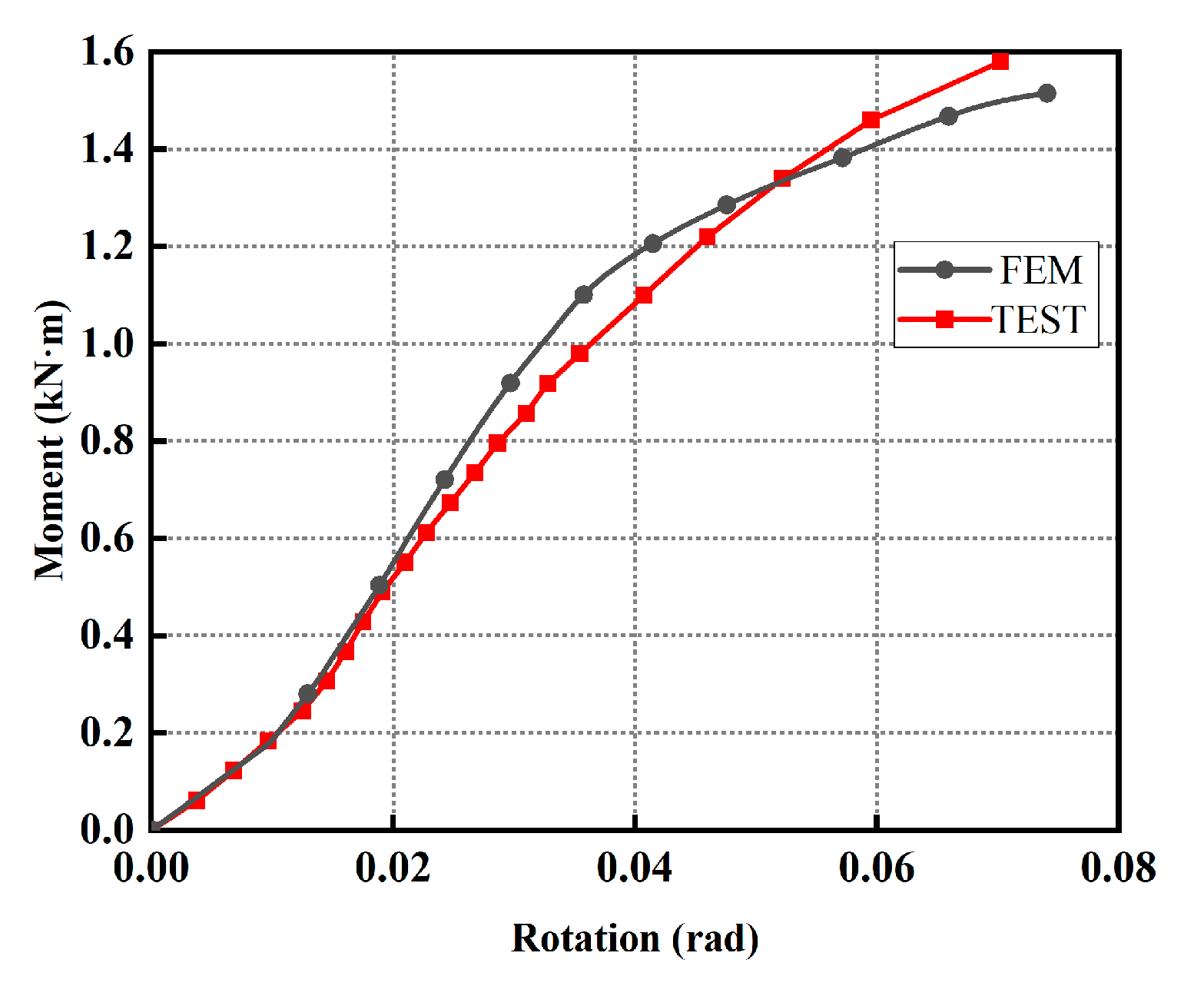
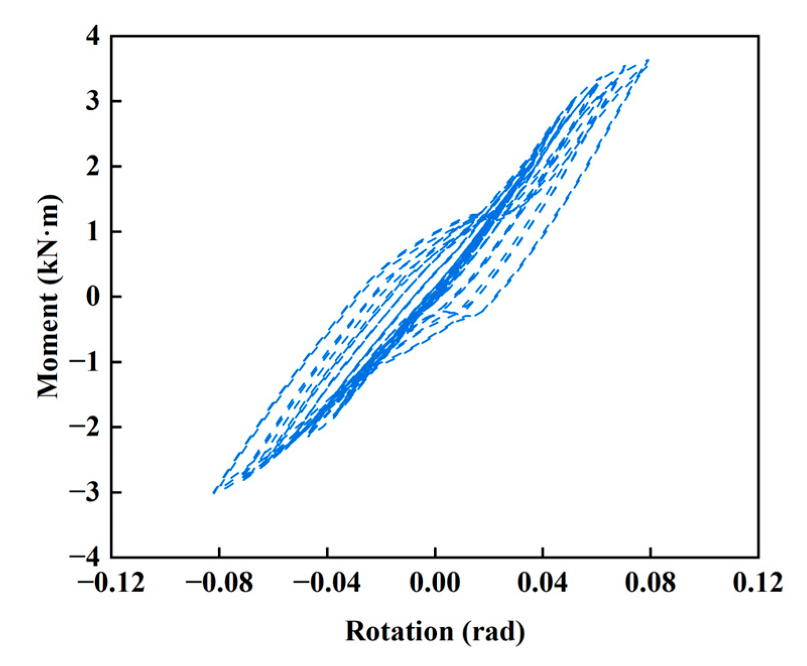
3.2. Semi-Rigid Behavior of Scaffold Joint

The semi-rigid behavior of scaffold joint has been widely acknowledged in structural engineering practice, with empirical evidence suggesting that conventional idealized assumptions of either hinged or fully rigid connections have been proven inadequate for simulating the load-transfer mechanisms and stability characteristics of scaffold systems [8,9,10,11]. A scaffold joint bending test is conducted on the MTS 322.41 test system, and a verified FE model is established to simulate the novel disc-buckle scaffold joint and accurately analyze its semi-rigid behavior. The constitutive relationship of steel materials based on the Chaboche hybrid strengthening model can achieve a simulation of monotonic loading and low cycle repeated loading [12]. After verifying the correctness of the finite element model of the scaffold joint based on the results of monotonic loading experiments, this paper conducts a simulation study on its low cycle performance to predict the low cycle performance of the scaffold joint. Figure 4a illustrates the bending test configuration for the proposed joint assembly, while Figure 4b presents the corresponding FE model. The upper and lower ends of the vertical pipes in the bending test are fixed and clamped by the upper and lower clamps of the MTS machine. In the finite element model, all degrees of freedom at the upper and lower ends of the pole are constrained to achieve fixed end constraints.
FE simulations implement two distinct loading protocols to investigate the mechanical response of the scaffold joint. Monotonic loading protocol in FE simulation is the same as the bending test. The description of monotonic loading protocol and cyclic loading protocol are as follows:
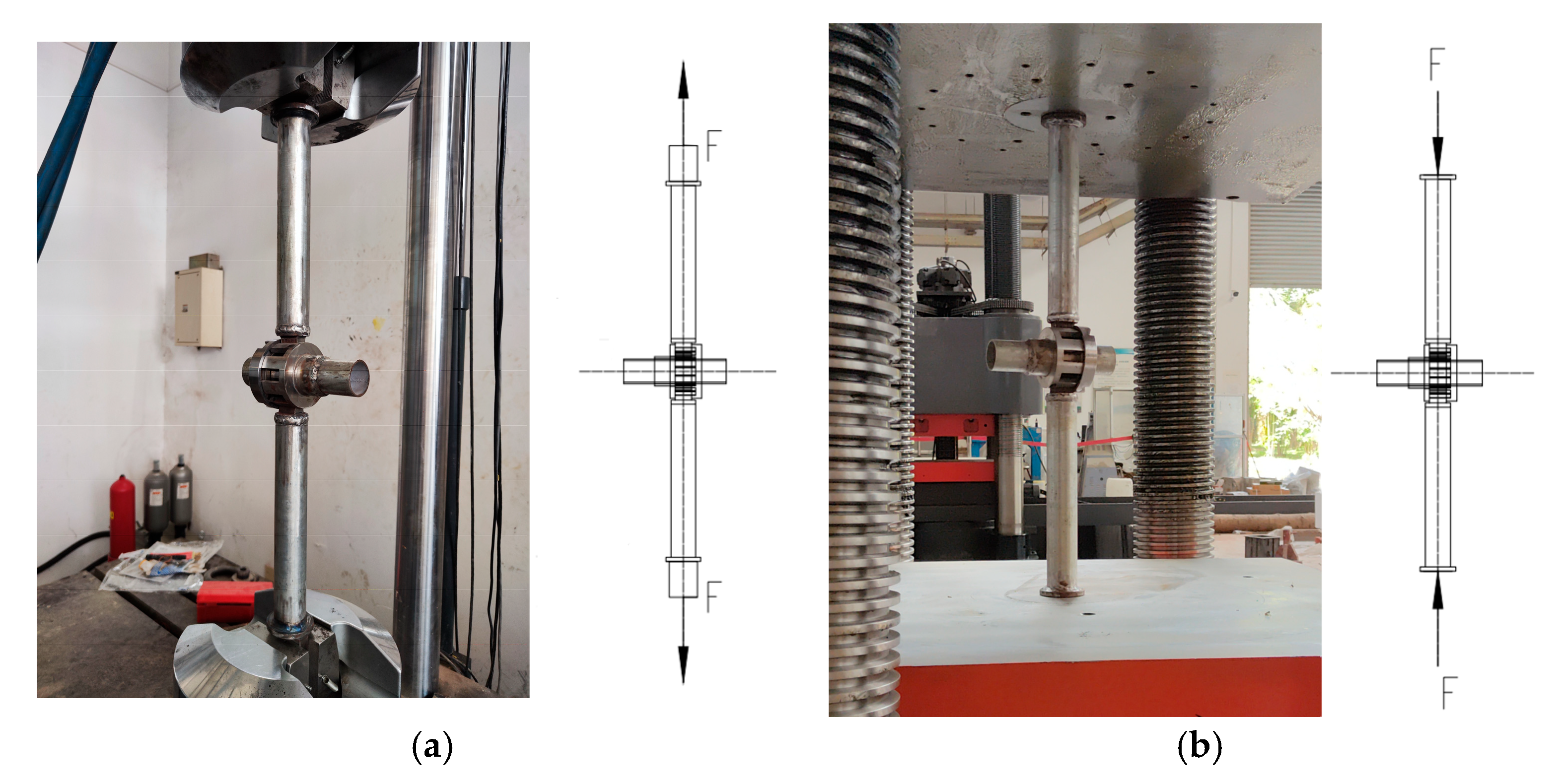
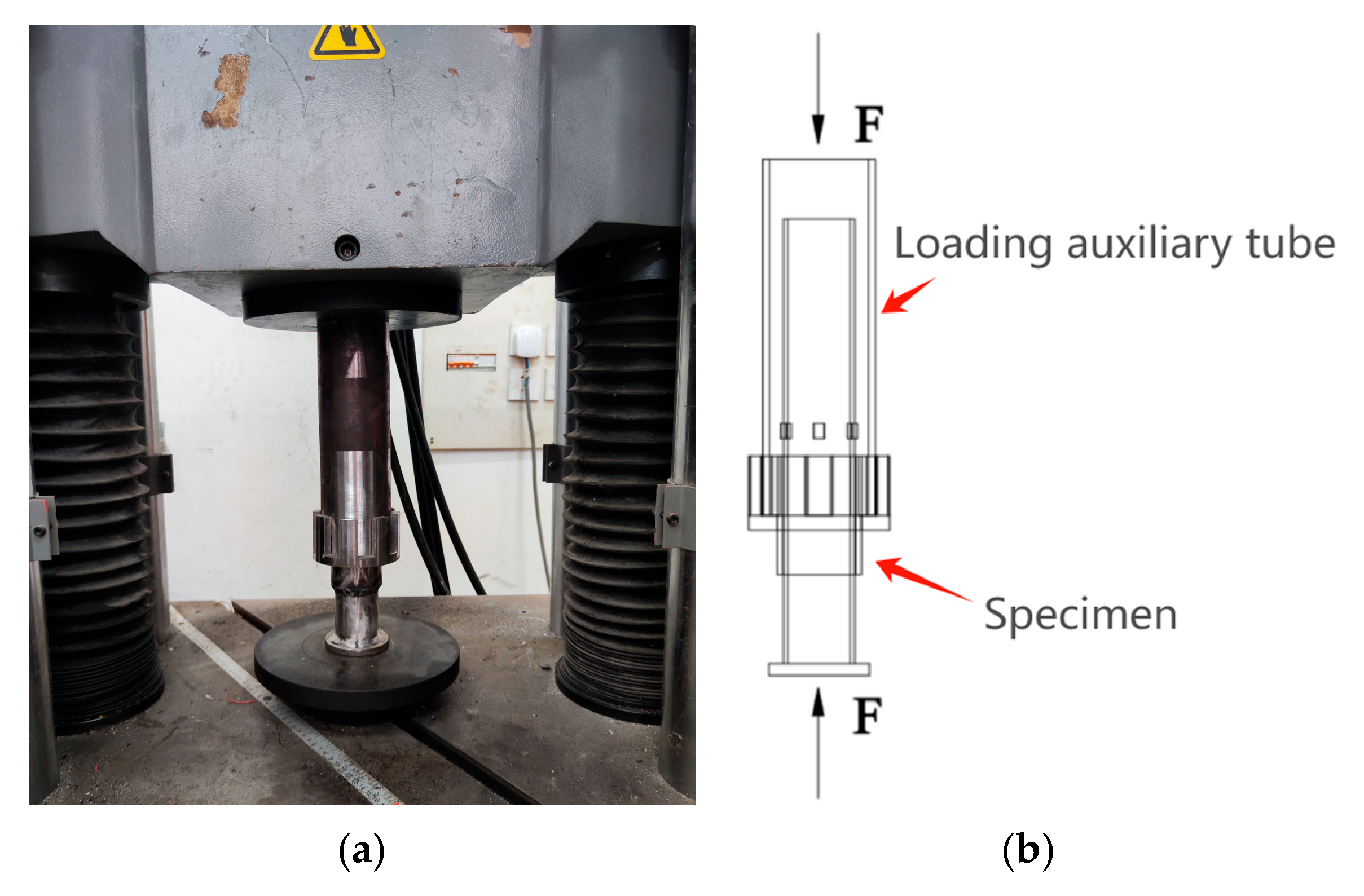
  • Monotonic loading protocol: A displacement-controlled vertical load was applied at the distal end of the horizontal member following ASTM E2126 standards [13], with a constant loading rate of 2 mm/min until structural failure;
  • Cyclic loading protocol: Quasi-static reversed cyclic loading was imposed, comprising three complete load–unload cycles at incremental displacement amplitudes of Δ = 20 mm, 40 mm, and 60 mm, respectively.
Figure 5 and Figure 6 present comparative analyses of deformation patterns between numerical simulations and experimental observations at ultimate loading states. The failure mode is characterized by localized yield at critical connection interfaces. The moment–rotation relationship depicted in Figure 7 reveals remarkable congruence between FE simulation and test. The vertical axis represents the bending moment carried by the joint. The horizontal axis represents the relative rotation angle between the horizontal pipe and the vertical pipe. Note that the force and displacement obtained in the test are measured by the instruments installed inside the MTS system, which are factory-calibrated. The maximum bending moment of the test result is 1.579 kN.mm, and the maximum bending moment of the finite element simulation result is 1.579 kN.mm. The difference between the two is 4.8%. Linear regression analysis yields a rotational stiffness of 34.5 kN·m/rad according to the test results, demonstrating a 72.5% enhancement over the prescribed value (20 kN·m/rad) in the Chinese technical code JGJ300-2013 [14] for temporary support structures. The stress and deformation of the joint are shown in Figure 7. The results indicate that the maximum stress is in the root of the teeth at the connection.
Figure 8 presents the von Mises stress distribution patterns under maximum loading conditions, capturing both peak positive and negative bending moment states during cyclic loading sequences. The maximum stress occurs at the plug-in point in the joint. Figure 9 shows the joint rotation angle and bending moment curves under low cycle reciprocating loading. It can be seen that the joint exhibits consistent bearing capacity and stiffness when subjected to positive and negative bending moments, demonstrating good symmetry.

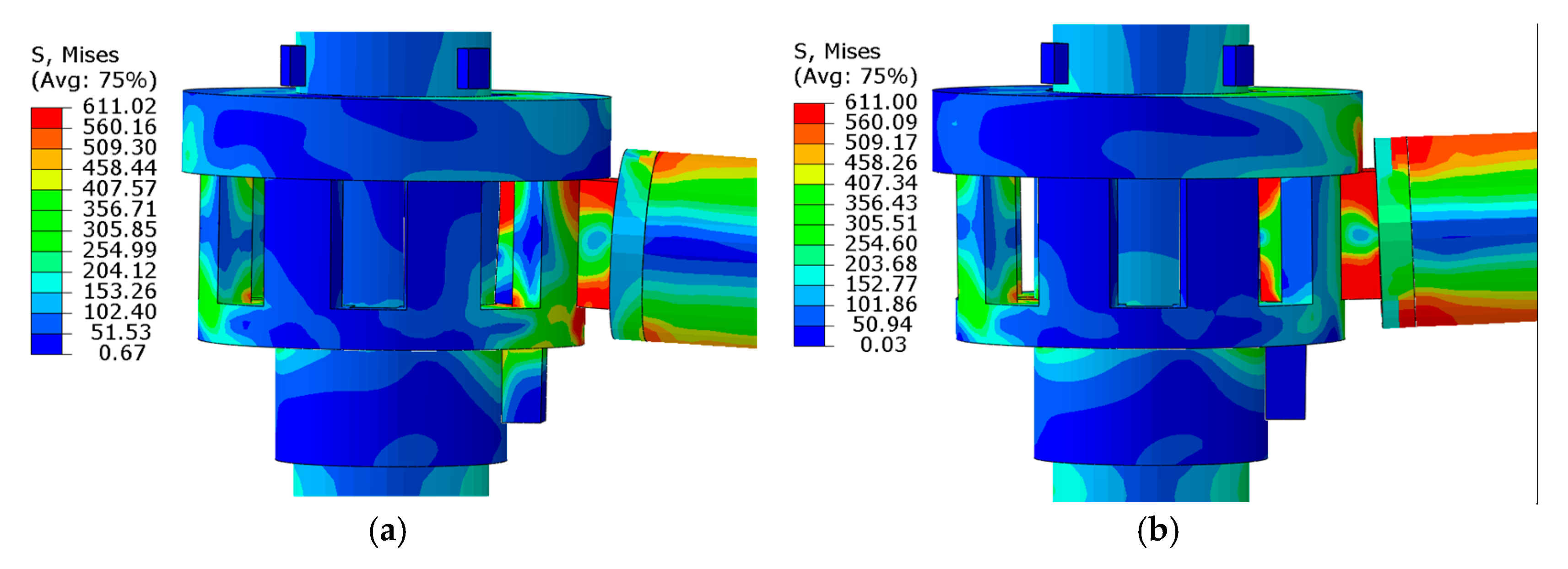
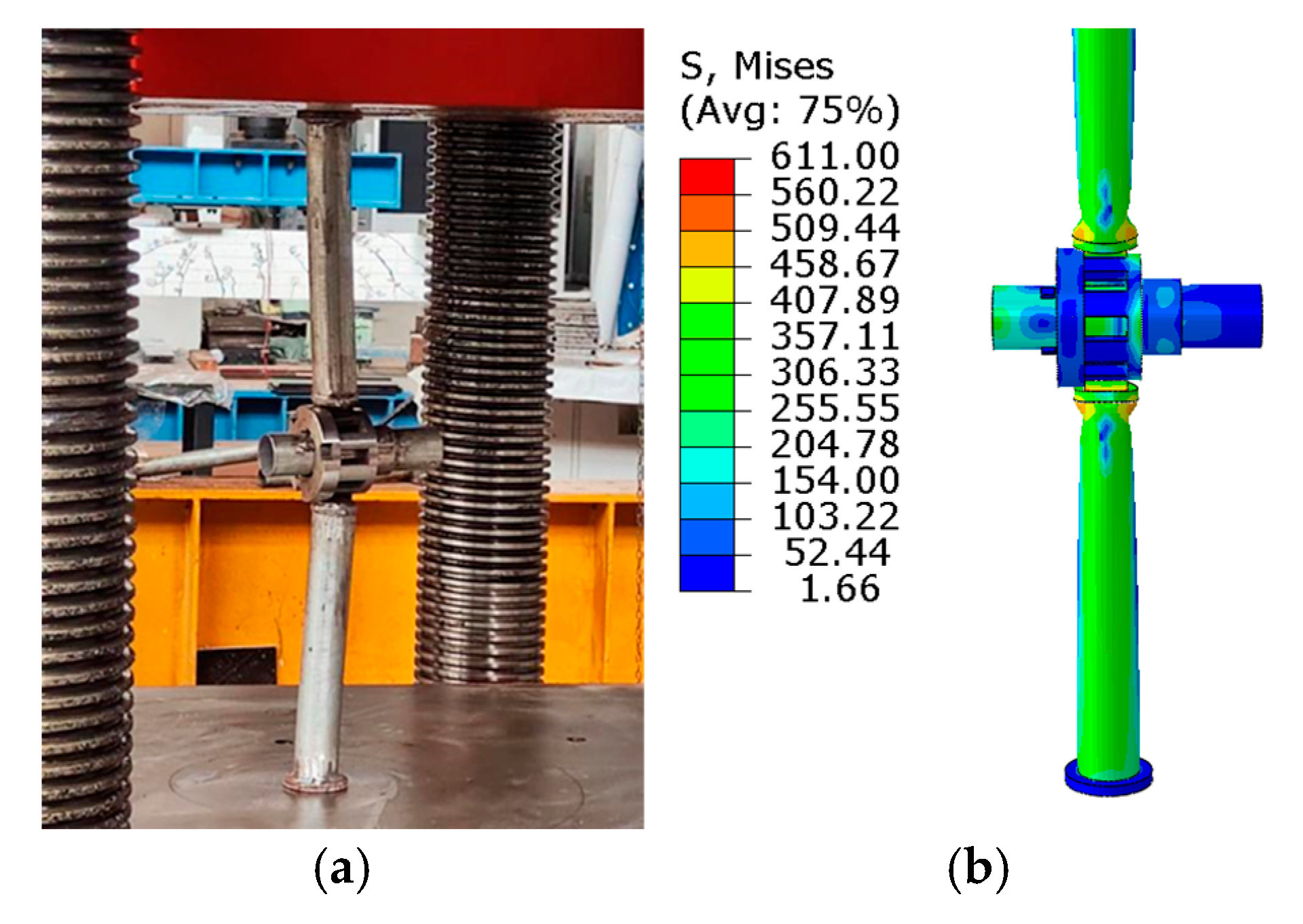
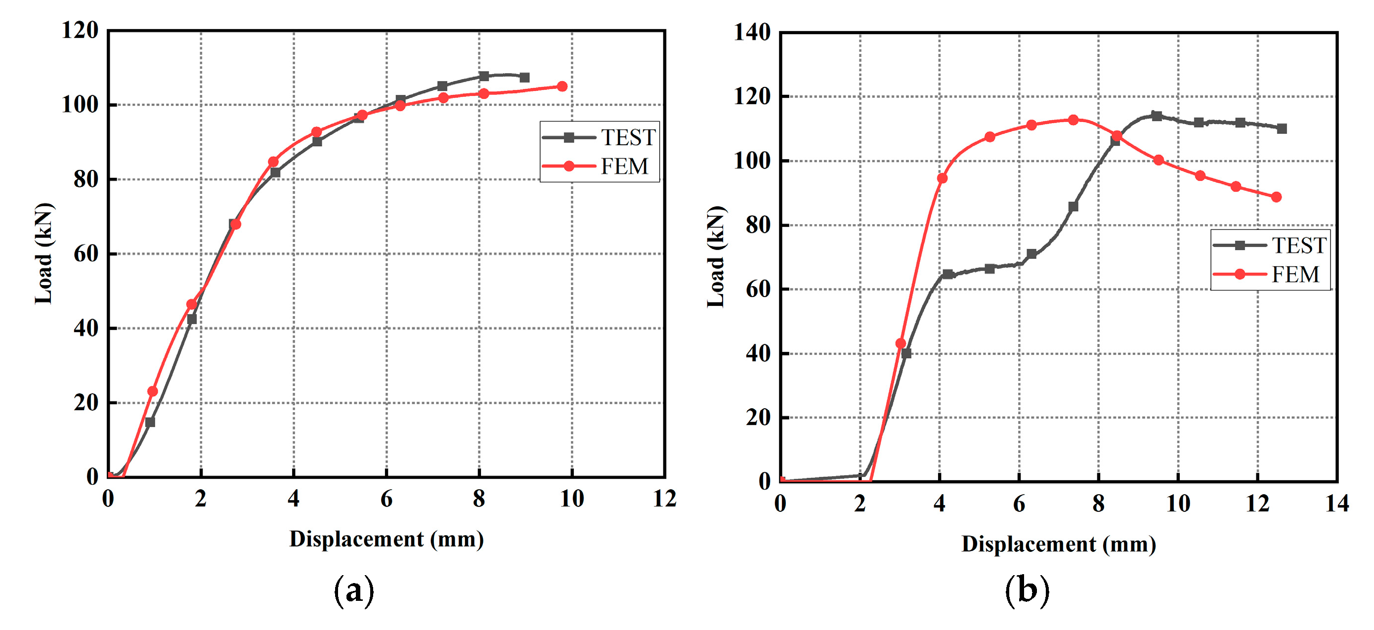
3.3. Analysis of Horizontal Tensile and Compressive Performance of the Joint

Scaffold joint systems are subjected to complex multiaxial loading conditions, encompassing not only vertical gravity loads but also significant tension–compression interactions from connected horizontal members [15,16]. The tensile test is conduct on the MTS 322.41 test system, as depicted in Figure 10a. The compression test is conduct on an electro-hydraulic servo pressure testing machine, as depicted in Figure 10b. Both tensile and compression tests are controlled by displacement, with a loading rate of 1 mm/min, and the test is stopped when the specimen fails. The force and displacement data of the two experiments were measured by the machine’s built-in sensors. The tensile test schemes are referenced in reference [15]. During the tensile test, the horizontal bars on both sides of the node specimen are clamped with machine clamps and subjected to tensile loading in a displacement-controlled manner. The boundary conditions of the finite element model are consistent with the actual experiments. Except for displacement control for loading direction, all other degrees of freedom at the upper and lower ends are constrained. Figure 10 shows the force reaction of the joint under the tension and compression action of the horizontal pipe. Figure 11 and Figure 12 show the failure mode comparison between FE simulation and experimental results. Tensile failure occurs on the fixed disc. Compression failure shows instability of the compression horizontal pipe. The load–displacement relationship between the finite element simulation and test is depicted in Figure 13. The curve obtained by the FE simulation and test is basically consistent. In the FE simulation, the maximum tensile bearing capacity is about 108 kN, and the maximum compressive bearing capacity is about 70 kN. In the test, the maximum tensile bearing capacity is about 105 kN, and the maximum compressive bearing capacity is about 67 kN. The maximum compression bearing capacity depends on the material strength, and the maximum compressive bearing capacity depends on the stability of the compression pipe. The tensile bearing capacity and compression bearing capacity are both meet engineering requirements. These findings provide critical insights for revising connection design provisions in temporary structure specifications.

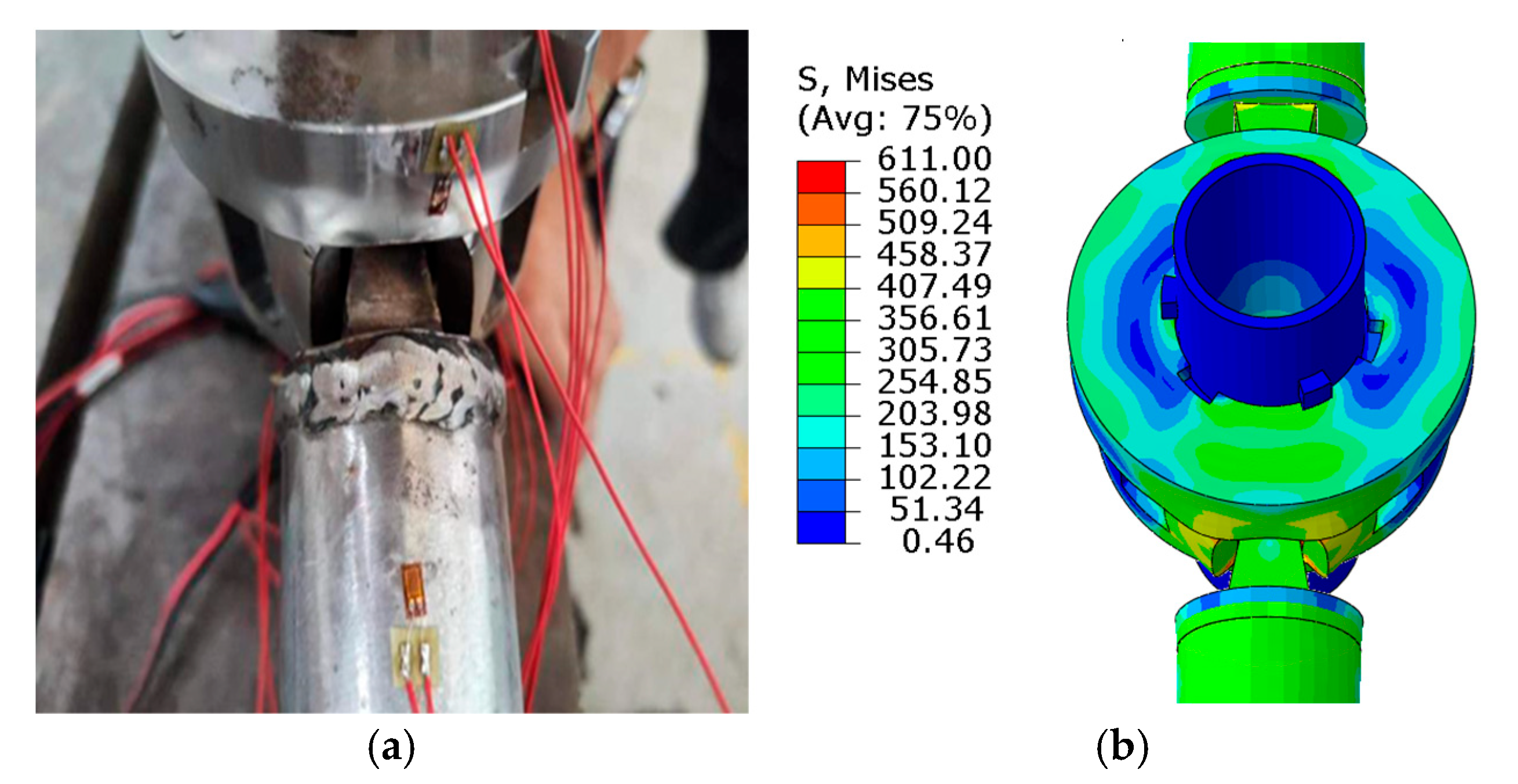
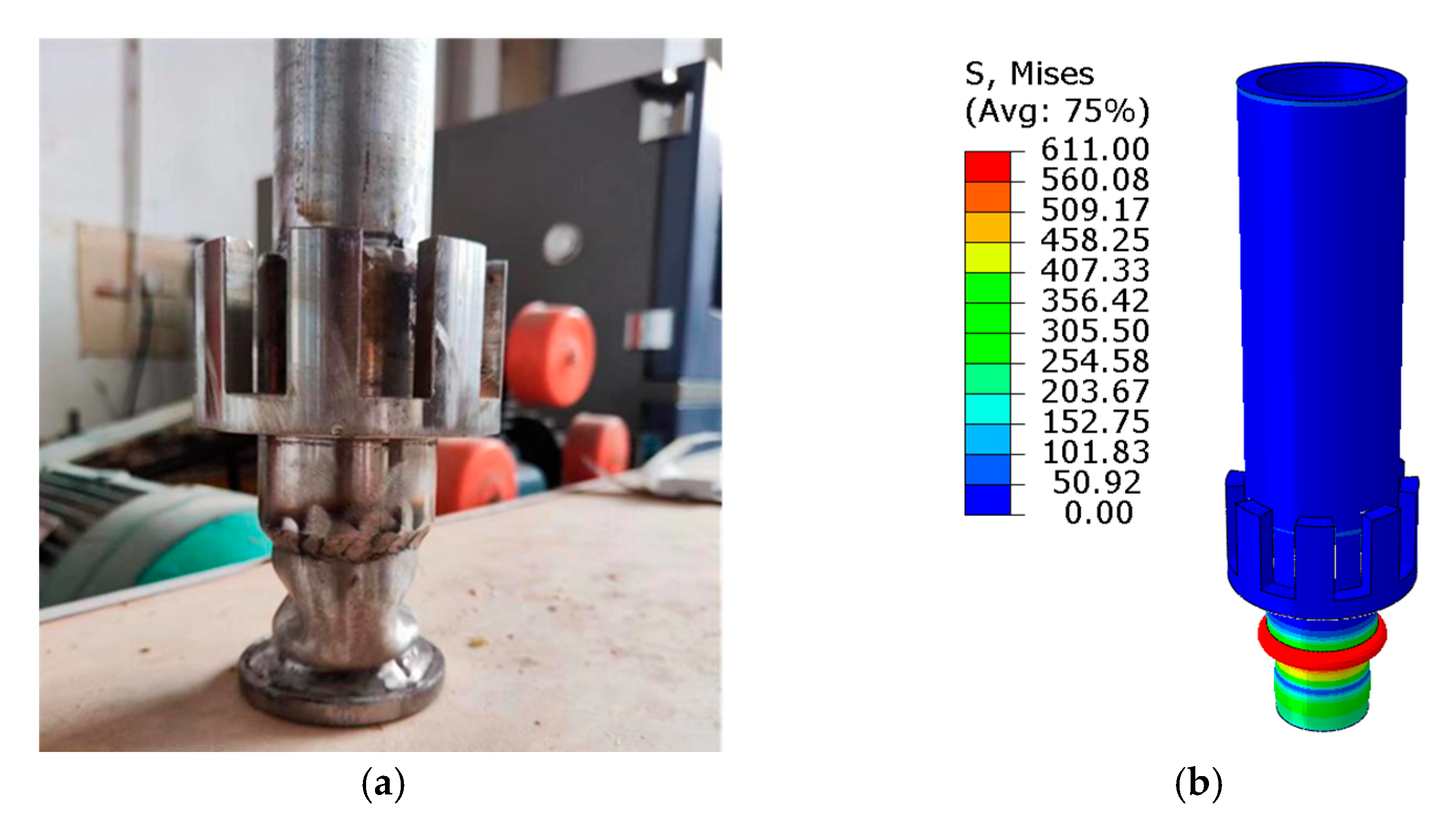
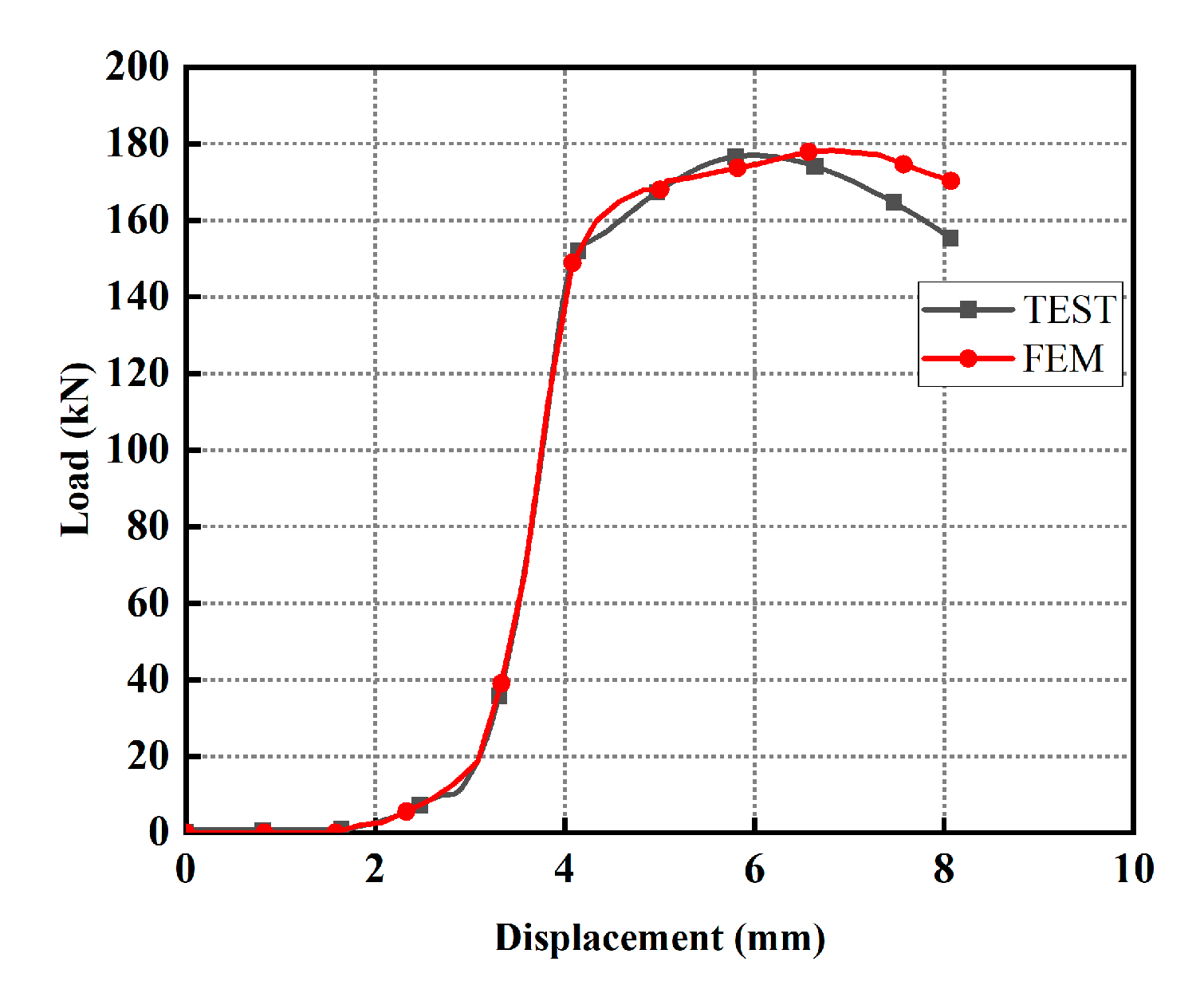
3.4. Shear Performance of Scaffold Joint

The structural joint must withstand shear forces induced by horizontal member loading, while weld connections shall satisfy prescribed bearing capacity criteria. The height of the weld seam is 5 mm, which is greater than the 3.5 mm required by the JGJ 130-2011 “Safety Technical Code for Steel Pipe Scaffolding with Fasteners in Construction” [17]. As shown in Figure 14, the lateral compression test of the node was conducted on an electro-hydraulic servo universal testing machine. Loading is controlled by displacement. The boundary conditions of the finite element model are consistent with the actual experiments. Figure 14 illustrates the schematic representation of the shear transfer mechanism. Figure 15 presents comparative analyses of shear failure modes between finite element (FE) simulations and experimental tests, revealing consistent buckling instability patterns in vertical members beneath the joint interface. Figure 16 displays the shear force–displacement curves between numerical and test, demonstrating ultimate shear capacities exceeding 180 kN. Post-failure examinations indicate localized buckling exclusively at the lower extremity of vertical members, with weld zones maintaining structural integrity throughout loading sequences. This failure mechanism confirms that the shear resistance of the scaffold joint is excellent.

4. Conclusions

The innovative disc-buckle scaffold joint developed in this paper demonstrates easy installation and excellent mechanical performance. Comprehensive evaluations combining nonlinear finite element analysis and testing validate its enhanced mechanical characteristics, with principal findings summarized as follows:
  • Experimental moment–rotation relationships yield an average rotational stiffness of 34.5 kN·m/rad, satisfying the JGJ300-2013 specification threshold of 20 kN·m/rad for temporary support structures [14].
  • The wedge-shaped plug-in structure maintains balanced load-transfer pathways. The novel scaffold joint also exhibits symmetric stiffness and bending moment under both positive and negative loading directions.
  • The joint has a large tensile and compressive bearing capacity in the horizontal pipe direction. The maximum tensile bearing capacity of the joint in the horizontal direction is about 108 kN, and the maximum compressive bearing capacity is about 70 kN.
  • The maximum shear bearing capacity of the joint exceeds 180 kN, and the shear resistance is greater than the buckling critical force of the vertical pipe, meeting the strength requirements.
Furthermore, considering the limitations in this study, several issues need to be addressed in further study: (1) investigation of the performance of an interior disc-buckle scaffold joint or a large-scale disc-buckle scaffold system since the focus of this study is a single exterior scaffold joint; (2) analysis of the effect of parameters on the behavior of disc-buckle scaffold joints; (3) the bearing capacity degradation considering steel corrosion or long-term loading.

Author Contributions

Conceptualization, S.W. and G.Z. (Genquan Zhong); investigation and resources, Y.X.; writing—original draft preparation, B.Y.; project administration, H.C.; writing—review and editing, G.Z. (Genquan Zhong); supervision, G.Z. (Guoyan Zhang). All authors have read and agreed to the published version of the manuscript.

Funding

This work was supported by Guangzhou Municipal Construction Group Co., Ltd. ([2021]-KJ016).

Data Availability Statement

All data generated or analyzed in this study are included in the published article.

Conflicts of Interest

Author Si Wei is employed by Guangzhou Research Institute of Construction Industry Co., Ltd. and Guangzhou Construction Engineering Co., Ltd.; Haofan Chen and Guoyan Zhang are employed by Guangzhou Construction Industry Development Co., Ltd. The remaining authors declare that the research was conducted in the absence of any commercial or financial relationships that could be construed as a potential conflict of interest.

References

  1. Feng, G.; Peng, Z. Application and problems of steel scaffolding in China. Steel Constr. 2017, 32, 97–100. [Google Scholar]
  2. Yuzhang, Z.; Ke, L. Safety accident of formwork engineering and its prevention in China. Archit. Technol. 2008, 07, 492–496. [Google Scholar]
  3. Jiaping, M. Achievement and development prospect of formwork and scaffold industry in China. Constr. Technol. 2009, 38, 16–18. [Google Scholar]
  4. Zhao, Z.; Liu, Q.; Kang, H.; Qian, J. A survey of bracing forms in braced frame structure. Ind. Constr. 2011, 41, 79–84. [Google Scholar]
  5. Zheng, Y.; Guo, Z. Investigation of joint behavior of disk-lock and cuplok steel tubular scaffold. J. Constr. Steel Res. 2021, 177, 106415. [Google Scholar] [CrossRef]
  6. ‌GB/T 228.1-2021; Metallic Materials—Tensile Testing—Part 1: Method of Test at Room Temperature. Standardization Administration of China: Beijing, China, 2021.
  7. JG/T 503-2016; Socket and Spigot Disc Lock Steel Tube Scaffolding Components. Ministry of Housing and Urban-Rural Development of China: Beijing, China, 2016.
  8. Chen, Z.; Lu, Z.; Wang, X.; Liu, H.; Liu, Q. Experimental and theoretical research on capacity of unbraced steel tubular formwork support based on sway frame with semi-rigid connection theory. J. Build. Struct. 2010, 31, 56–63. [Google Scholar]
  9. Lu, Z.; Chen, Z.; Wang, X.; Guo, C.; Liu, Q. Study of the bearing capacity of fastener steel tube full hall formwork support using the theory of stability of pressed pole with three-point rotation restraint. China Civ. Eng. J. 2012, 45, 104–113. [Google Scholar]
  10. Zou, A.; Li, Q.; He, M.; Zhang, H. FEA on bearing behavior of cuplok scaffold based on tri-linear semi-rigid joint model. J. Build. Struct. 2016, 37, 151–157. [Google Scholar]
  11. Xiangyang, X.; Guo, C.; Lei, Y. Multi-parameter simulation method of semi-rigid node of steel tubular scaffold with coupler. J. Civ. Environ. Eng. 2019, 41, 92–103. [Google Scholar]
  12. He, Z.; Chen, H.; Zhong, G.; Zhou, Y. Seismic performance of end-reinforced steel pipe dampers: Laboratory test and numerical investigation. J. Constr. Steel Res. 2023, 208, 107994. [Google Scholar]
  13. ASTM E2126-21; Standard Test Methods for Cyclic (Reversed) Load Testing for Shear Resistance of Vertical Elements of the Lateral Force Resisting Systems for Buildings. ASTM International: West Conshohocken, PA, USA, 2021.
  14. JGJ 300-2013; Technical Code for Temporary Support Structures in Construction. China Architecture & Building Press: Beijing, China, 2013.
  15. Cheng, X.; Li, Y.; Wu, B.; Zhang, Y. Research on the compressive performance of plug-pin scaffold joints in low-temperature. J. Constr. Steel Res. 2024, 216, 108497. [Google Scholar]
  16. Li, Y.; Zhang, Y.; Zhang, Y.; Wu, B.; Cheng, X. Research on the tensile performance of plug-pin scaffold joints in low-temperature. J. Constr. Steel Res. 2024, 216, 108589. [Google Scholar] [CrossRef]
  17. JGJ 130-2011; Safety Technical Code for Steel Pipe Scaffolding with Fasteners in Construction. Ministry of Housing and Urban-Rural Development of the People’s Republic of China: Beijing, China, 2011.
Figure 1. Research and development strategy.
Buildings 15 02034 g001
Figure 2. New disc-buckle scaffold joint. (a) Detail of the joint; (b) finite element geometric model; (c) the ringlock disc; (d) detail of the pin.
Buildings 15 02034 g002
Figure 3. Installation processes of the novel scaffold joint. (a) Step one: insertion and compression; (b) step two: rotational alignment; (c) step three: vertical engagement; (d) step four: impact fixation.
Buildings 15 02034 g003
Figure 4. The novel disc-buckle scaffold joint specimen. (a) Bending test configuration; (b) FE model for monotonic loading and quasi-static reversed cyclic loading simulation.
Buildings 15 02034 g004
Figure 5. Deformation characteristics of finite element and experimental loading in the final state. (a) Bending test; (b) FE simulation.
Buildings 15 02034 g005
Figure 6. Failure mode comparison between bending test and FE simulation. (a) Bending test; (b) FE simulation.
Buildings 15 02034 g006
Figure 7. Rotation–moment curve of joint.
Buildings 15 02034 g007
Figure 8. Stress cloud map of joint under maximum positive and negative bending moments. (a) Positive; (b) negative.
Buildings 15 02034 g008
Figure 9. Joint rotation angle and bending moment curve under reciprocating loading (FE simulation).
Buildings 15 02034 g009
Figure 10. Sketch of tensile and compressive forces in the horizontal pipe direction of joint. (a) Tensile; (b) compression.
Buildings 15 02034 g010
Figure 11. Tensile failure modes between FE simulation and test. (a) Test; (b) FE simulation.
Buildings 15 02034 g011
Figure 12. Compression failure modes between FE simulation and test. (a) Test; (b) FE simulation.
Buildings 15 02034 g012
Figure 13. Tensile and compression load–displacement curves comparison between FE simulation and test. (a) Tensile; (b) compresion.
Buildings 15 02034 g013
Figure 14. The shear sketch of the scaffold joint. (a) Specimens installation; (b) detailed drawing of specimen structure and force diagram.
Buildings 15 02034 g014
Figure 15. Failure mode between test and FE simulation. (a) Test; (b) FE simulation.
Buildings 15 02034 g015
Figure 16. Shear force and displacement curve comparison between FE simulation and test.
Buildings 15 02034 g016
Table 1. Material parameters.
ItemDetail
(mm)
Length
(mm)
Elastic Modulus (MPa)Yield Strength (MPa)
Vertical pipeφ48.3 × 3.215002.09 × 105345
Horizontal pipeφ48.3 × 3.215002.09 × 105235
Other--2.09 × 105345
Disclaimer/Publisher’s Note: The statements, opinions and data contained in all publications are solely those of the individual author(s) and contributor(s) and not of MDPI and/or the editor(s). MDPI and/or the editor(s) disclaim responsibility for any injury to people or property resulting from any ideas, methods, instructions or products referred to in the content.

