1. Introduction
The Neapolitan domes, dating back to when there was no clear distinction between political and religious power, are characteristic of religious architecture, which was closely intertwined with the social history of Naples. They represent a distinctive element not only from an architectural standpoint but also from a structural one, as their history is inevitably linked to the region’s seismicity, which has posed significant challenges to preserving architectural heritage [
1,
2,
3,
4,
5,
6,
7,
8,
9,
10].
The vaulted covering has long symbolised the connection with the divine across various cultures, as it serves as a metaphor for the celestial vault. In Plato’s Timaeus, the sphere is considered the symbol of completeness, the element that contains all forms, and is the closest to perfection and, thus, to God. Furthermore, the domed space, with its volumetric complexity and pronounced vertical development, proposes itself as the architectural materialisation of the Axis Mundi, erected in the heart of the temple as a connection between the material and spiritual dimensions, serving as a pathway of union between man and God [
11,
12,
13,
14,
15,
16].
As is well established, the city of Naples is located in a geologically active region, which renders the area susceptible to frequent seismic tremors of varying intensities. In this context, the Neapolitan domes, originally designed to withstand vertical loads, may exhibit vulnerabilities to the horizontal forces induced by an earthquake [
17,
18,
19,
20,
21].
In this paper, we aim to highlight how the behaviour of domes to horizontal actions is not influenced by strength factors but rather by balance factors. Thus, the study of such structural components typical of ancient monumental buildings can be traced back to simple geometric problems.
The approach aims to determine the safety of the dome designs by introducing horizontal forces proportional to the weight of the structures. The method is based on determining a class of purely compressive stress regimes balanced with the applied load. In the unilateral model for masonry (Heyman’s model), the mere existence of such a stress class proves the structure’s safety. These members can be used to evaluate the geometric safety of the structure and estimate the limits on the thrust forces exerted on its boundaries.
The graphical method uses the slicing technique that does not consider the hoop compressive stresses that develop in the upper part of the domes. As a result, the geometric safety factor obtained with graphical methods for the domes alone is lower than that usually obtained with the purely analytical method.
The decision to work with masonry using methodologies that take into account only the problems of geometry and balance dates back to the early 1990s, when some brilliant Italian professors such as Salvatore Di Pasquale [
22], Edoardo Benvenuto [
23], Antonino Giuffre [
24], and Doglioni [
25] (survey), and international such as Heyman [
26], etc. began a path of research without regard to classical structural mechanics and the Theory of De Saint Venant. They resumed reading the ancient treatises and began to wonder why ancient structures were in such good health after millennia, having been built at a time when there was no knowledge of modern elastic theory.
And so they began to doubt that the classic duality between the force–displacement and tension–deformation pairs was always valid, even in the case of materials with well-defined characteristics, such as non-tensile strength, sudden and brittle breakage, and absolute non-deformability.
All of the architectural heritage is built with a material that corresponds to these characteristics: masonry.
Masonry has a thousand typological aspects; therefore, it is indefinable by definition, but scholars have managed to group together the salient and common characteristics to elaborate a theory.
Today, many other researchers follow the path traced in the 1990s, but the path is still difficult because sometimes someone is tempted to talk about stress. Many valid theories have been developed in those years, all with the common denominator of abolishing the concept of resistance to the material and considering an approach of equilibrium, that is to say, resolving the problem through the statics or the kinematics of rigid bodies.
For ancient structures, the problem can be summarised as controlling their actual condition. They also show vulnerability concerning future events or the very duration of their life in optimal conditions [
27,
28,
29,
30,
31].
According to the authors, there can be no single methodology for dealing with masonry, as in this term so broad that an extensive range of material types are included, from the squadred blocks and put into practice in good order, the orthostats and diathons (
ortostati e
diatoni) in the masonry
isodoma and
pseudo isodoma, passing through an undefined number of constructive types, from those “cultured” to those “popular” [
24], until we reach the sack masonry that so severely betrayed the Italian historic centres during seismic events [
32,
33,
34,
35,
36].
If, therefore, it is not possible to establish a single typology and, consequently, a single model for the material, a calculation methodology can be defined for each structural component that it is extendable to the whole specific category to which the element in question belongs (e.g., dome type), but differs only as an approach from that reserved for other components.
This methodology appears appropriate, in that the constructions of historical heritage, when examined as individual decoupled problems, are composed precisely of repetitive structural components. The vertical elements are always represented by whole or more-or-less whole walls and individual masonry piers. In contrast, the horizontal elements are arches, vaults, domes, and, more rarely, architraves, which are unsuitable to cover large lights.
This results in an approach based on geometry rather than strength.
In this work, also based on previous research, the authors are concerned with defining a general method of calculation for domes constructed from non-reactive tensile material. In particular, the study focuses on the structural behaviour of hybrid systems in which two materials with distinct mechanical characteristics—timber and masonry—interact within a single construction. The proposed approach combines finite element modelling of the elastic response of timber with a limit analysis based on Heyman’s assumptions for masonry, aiming to integrate these frameworks within a coherent methodology rather than treating them separately.
2. Domes and Earthquakes in the History of Naples
Throughout history, Naples has experienced several catastrophic earthquakes that have severely impacted its architectural structures. In this context, we aim to focus specifically on certain domes [
37] and the effects of earthquakes, although systematic cataloguing of all the domes and the earthquake-related devastations over the years would be necessary [
38].
2.1. 1456
One of the most devastating earthquakes was the earthquake of Central and Southern Italy in 1456, in the Central–Southern Apennines, Campania—with a magnitude of 7.30—on 5 December 1456. This earthquake caused numerous churches’ destruction and several domes’ collapse due to the severity of the tremor. As reported by Mario Baratta in Terremoti d’Italia [
39], “Naples was heavily damaged. The church of St. Giovanni Maggiore was completely ruined, as was the church of St. Maria Maggiore. Two towers in front of the Vescovado were half-destroyed, as were the bell tower of St. Arpino and that of St. Eligio. In the church of St. Agostino, almost an entire lateral nave collapsed; the choir was also damaged, and the rest of the building was affected. The church of St. Domenico was left with its facade entirely damaged; St. Lorenzo’s church was only slightly damaged, but its dormitory and living quarters were nearly destroyed. The church of St. Chiara suffered many fissures, and part of the cloister was shaken; the church of the Incoronata had several cracks. As did the Palazzo del Capitano, many houses collapsed; the Zecca mostly fell. Five merlons from the middle tower of Castel dell’Ovo fell, and fissures appeared in its church. Castel Sant’Elmo was severely damaged. All the undamaged houses remained open. Approximately 100 people perished”.
2.2. 1688
Another disastrous earthquake was that of 1688 in the Sannio region, where, in Naples, “The great dome of the temple of the Casa Professa dei Gesuiti collapsed, along with two smaller ones, and large and dangerous fissures opened throughout the entire building: many people were trapped under the rubble. All the buildings belonging to the company were also damaged. Among the buildings that suffered from the earthquake were the dome of the Tesoro and the churches of the PP. Minoriti, of S. Martino, of the Sanità, of S. Tomaso, of the PP. Domenicani, of S. Maria della Verità, of the SS. Annunziata, the Carmelitani Scalzi of the Madonna della Pietà, and the PP. Benedettini must be noted; the Carmelite church had its bell tower and two dormitories damaged; the same fate befell those of the Royal Monastery of S. Chiara, of S. Ligorio, of the Croce di Lucca, of S. Gaudioso, most of which were ruined from the foundations, and the same can be said of all the other monasteries, especially that of S. Maria. The royal palace, some city gates, and Castel Capuano were also damaged. As for private buildings, no house or palace was not affected. The number of deaths was reported to be 50, in addition to many injuries”.
2.3. 1694
In the earthquake of 1694 in Irpinia–Naples, “The churches, palaces, and other buildings were more or less damaged, but there was no significant destruction, nor were there any casualties to mourn. The most significant damage was as follows: The church of the Archdiocese suffered damage to the main altar, a nave, the chapel of S. Gennaro, and the dome, the small dome of the church of the PP. Gerolomini had to be demolished; the church of S. Lorenzo was damaged; a wall collapsed in the monastery of S. Francesco; the dome of S. Maria Maggiore was damaged, and some fissures appeared in the churches of S. Maria di Cort., of Gesù e Maria, of S. Teresa, of S. Paolo, of S. Pietro ad Ara, and of the SS. Annunziata: in the church of Maddalena, a loggia collapsed; the churches of S. Giorgio, S. Maria della Pace, S. Giovanni a Mare, and Carminello suffered significant damage. In the Porta Nolana district, a house collapsed, injuring a young girl. In the convent of Curmine, the iron cross on the bell tower fell, along with a large stone. The monasteries of S. Chiara, of S. Spirito, of the Trinità, the Jesuit college, the Maddaloni palace, and the Duke of Monteleone were also damaged. The churches and monasteries of S. Gregorio Armeno, the bell tower of S. Severino, the church and convent of Sanità, S. Maria della Stella, the convent of S. Agostino, the Incurabili, S. Carlo fuori Porta S. Gennaro, etc., were not spared. In short, only a few houses remained undamaged”.
These events have tested the vaulted structures, highlighting their strength and vulnerability; indeed, these structures, designed primarily to withstand their own weight and vertical loads from lanterns and skylights, often struggle to endure horizontal forces and ground settlements caused by earthquakes.
Such a condition does not imply that domes “collapse” or trigger collapse mechanisms in the presence of horizontal forces; instead, they seek a new equilibrium configuration, which may occur through the formation of cracks.
The cracks, referred to in structural mechanics as unilateral hinges, assist the structure in finding a new equilibrium configuration. Just as the mechanical system becomes unstable when the hinges align, the arch or dome will only collapse if the openings exceed the geometrical limit of stability. Therefore, they collapse due to the loss of equilibrium, not due to the material’s lack of resistance (
Figure 1a–c).
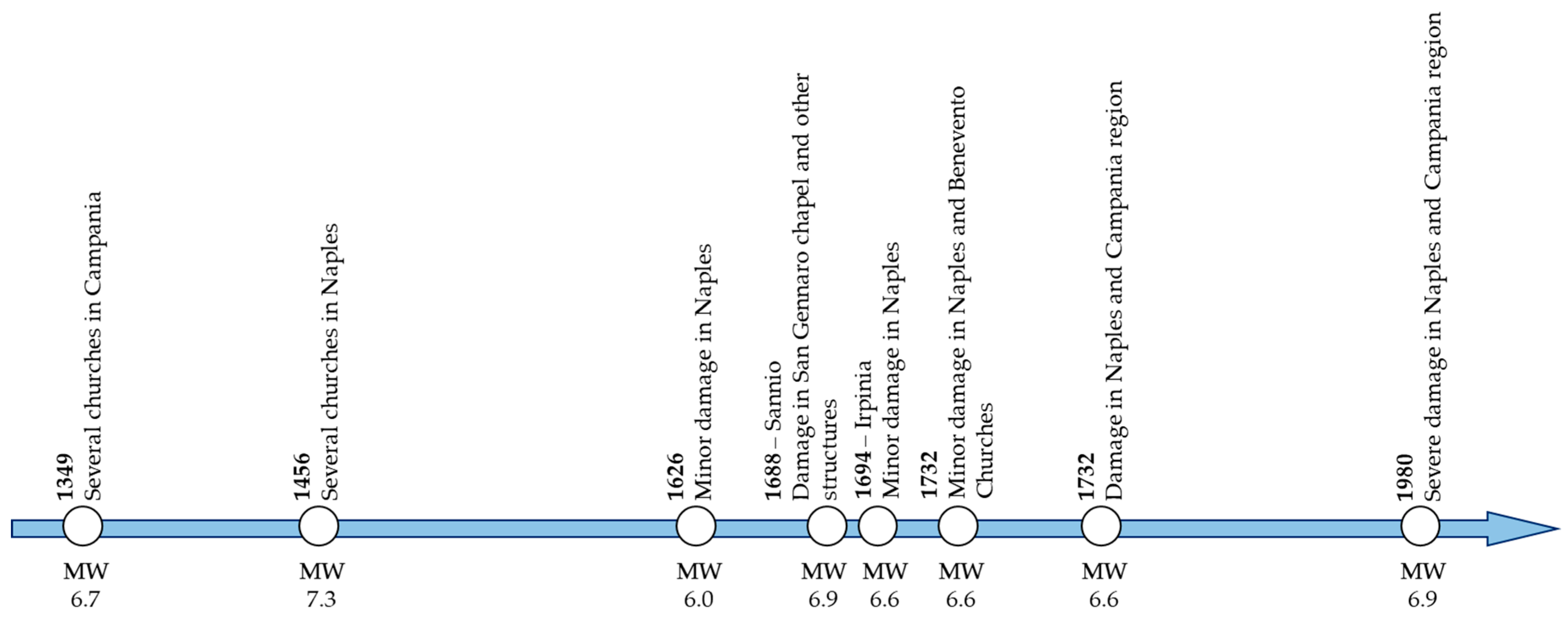
A synthetic timeline is presented to provide a broader historical framework for the seismic vulnerability of heritage buildings in the Naples region (
Figure 2). This visual representation summarises the major seismic events that occurred from the 14th to the 20th century, indicating their estimated magnitudes and the principal architectural structures affected. The timeline complements the historical narrative by illustrating the recurrence and intensity of earthquakes that have challenged the stability of significant historical constructions, including, in particular, domes such as that of the Tesoro di San Gennaro.
3. Damaged Domes: A Comparison Between Two Case Studies
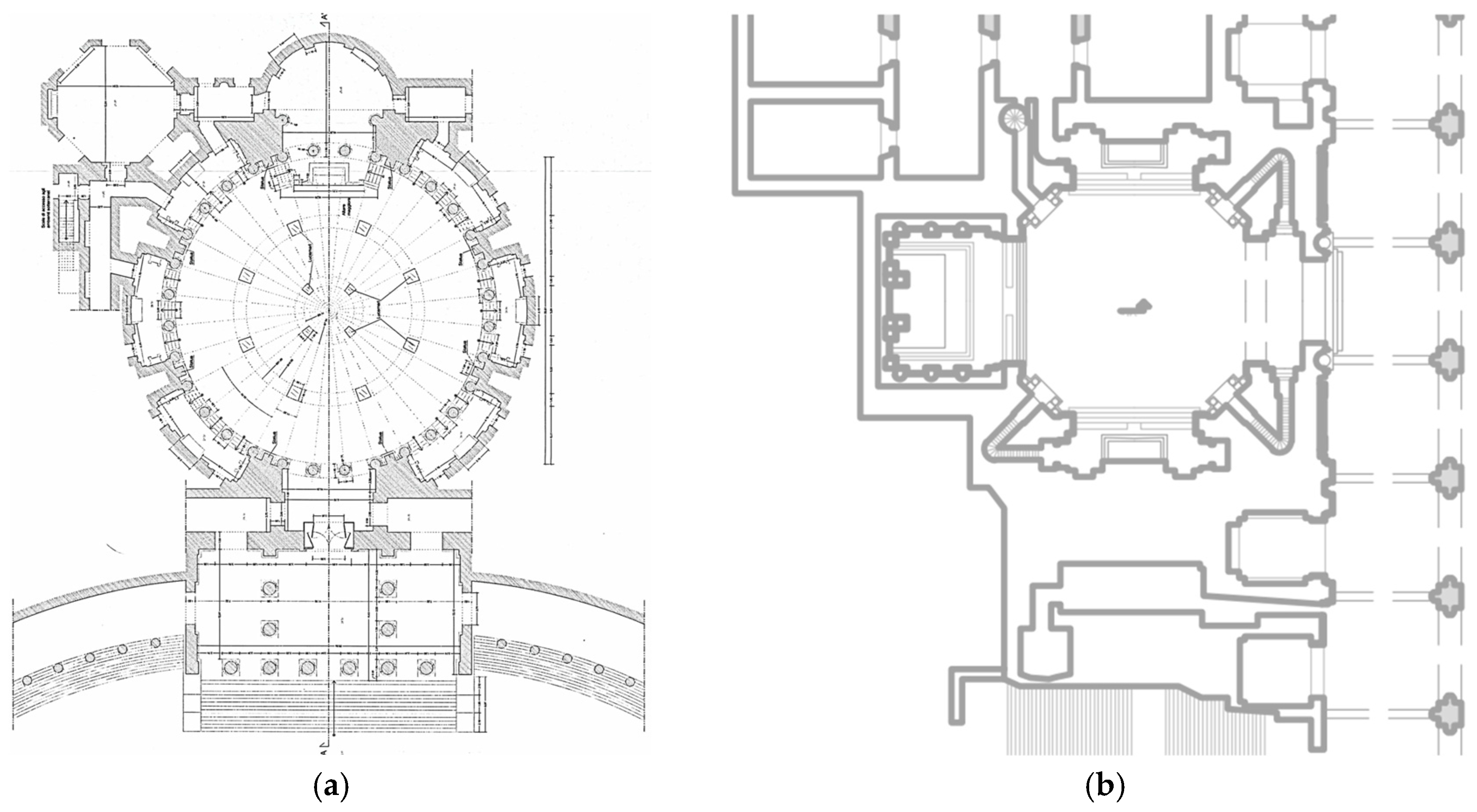
The two domes under examination differ from each other, as the Dome of San Francesco di Paola is a neoclassical structure built around the first half of the 1800s (the dome is almost hemispherical, a clear reference to the Pantheon), with a diameter of 36 m and a height from the floor of 53 m, with a central opening approximately 8 m in diameter ([
41,
42,
43,
44],
Figure 3a). In contrast, the Dome of San Gennaro also rises above Naples to a height of 53 m but has a diameter of “merely” 14 m, erected around the mid-1600s, two centuries earlier [
42,
43],
Figure 3b).
One of the main differences between the two cases is that the lantern on top of San Francesco di Paola serves a stabilising function, while the history of the lantern of San Gennaro is more complex. It was replaced, and in its place (from a static point of view, as will be explained further), a wooden reticulated structure was inserted, necessitating the insertion of an elastic calculation factor in the structural analysis.
The neoclassical dome of San Francesco di Paola and the baroque dome of the Tesoro di San Gennaro share their height and seismicity in the location where they are situated, despite being built in different eras.
The first, constructed around 1817, has never been considered an example of architectural excellence by architectural historians due to its excessive similarity to the Pantheon, which made it appear as a mere copy and its neoclassical style. However, for a scholar of form and structure, and in the relational dynamics between balance and geometry, the dome of San Francesco di Paola represents an example of bold construction. Its iron and glass lantern has remained in place since the year of construction, providing a stabilising effect [
43,
44,
45], and any small disturbances can be attributed to the indiscriminate closure of the ventilation shafts present in the connection between the upper and lower shells of the dome.
The dome of the Tesoro di San Gennaro, a baroque gem known for its soaring shape that dominates the skyline of Naples, on the other hand, suffered, due to the heavy lantern made of Piperno stone and Sorrento stone, from its initial construction. The inner shell is a perfect hemisphere, while the outer shell is a rotational semi-ellipsoid with a steep curve. Both shells are constructed of tuff, with the exterior covered in solid bricks.
Initially, the lantern was supported by a small tambour, a double-layer brick structure that rested on the oculus of the lower hemispherical shell.
As mentioned in the previous section, in 1688, a strong earthquake caused significant damage to the dome, the lantern, and the tambour. The seismic event, likely exacerbated by the excessive weight of the upper substructure (the tambour–lantern system), caused multiple vertical cracks in both shells, and the collapse of the tambour itself and parts of the outer cladding.
It may be interesting to compare the two domes (
Table 1) and the different types of damage observed in the dome of San Francesco di Paola [
41] and in the dome of San Gennaro.
3.1. Dome of San Francesco Di Paola
In addition to studies concerning the constructive characteristics of the building and the accurate geometric reconstruction of the dome, the survey of cracks plays a crucial role in identifying the mechanical behaviour of ancient constructions. As is well known, in order to allow for movement, a rigid structural element must be capable of developing cracks. Indeed, large movements in historical masonry structures (due to differential settlement in the foundation, construction defects, or material settling) are very common [
41,
44].
For the investigation process, commissioned by the Provveditorato alle Opere Pubbliche of Naples and carried out by the company TecnoIN GeoSolution between the first and second decades of the 2000s, the dome was divided into 32 vertical segments (Meridians) and 7 horizontal segments (Parallels). The final result consists of 224 portions (Lacunaries) mapped onto a planar surface.
Technicians often exhibit the presence of cracking patterns excessively. Almost all masonry structures reveal cracks due to slight movements in the supporting structures and small misalignments between the blocks and between different structural elements.
In fact, most of these cracking patterns appear in the early years of a building’s life, following construction, and are considered physiological. Among these minor and frequent disturbances, we can include the southern cracks that develop in the dome’s drum and in its lower part, located below the impost.
The dome of San Francesco di Paola is expected to have superficial settling cracks and plaster detachments, primarily due to changes in the ventilation system that had originally been designed. Indeed, there was an air duct between the double shell, and its closure likely induced such cracking in the structure.
3.2. Dome of San Gennaro
The original design of the dome of the Treasury of San Gennaro, built in the first half of the 17th century based on the drawings by Francesco Grimaldi, consists of a double shell with a passing space, topped by a lantern made of Piperno and Sorrento stone [
42,
43]. The dome is part of the Neapolitan tradition of double-shell domes, which combine structural, functional, and aesthetic considerations [
46]. The inner shell is a perfect hemisphere, while the outer shell is a rotational semi-ellipsoid with a raised profile. Both shells are made of tuff, with the outer surface covered in solid bricks. Initially, the lantern was supported by a small tambour, a double-layer brick structure resting on the oculus of the lower hemispherical shell.
In 1688, a strong earthquake damaged the dome, the lantern, and the tambour. The effect of the earthquake, likely compounded by the excessive weight of the upper substructure (tambour–lantern system), caused numerous vertical cracks in both shells and the collapse of the tambour itself, along with parts of the external cladding.
At the beginning of the 18th century, the Deputation commissioned technicians to assess the monument’s structural integrity. Debates arose over the best methods for consolidating the chapel, particularly due to the frescoes by Giovanni Lanfranco on the inner shell, which led to differing opinions on intervention strategies. Experts proposed various solutions, ranging from no intervention to significant structural modifications. In 1707, Giuseppe Lucchese argued that the masonry tambour could not withstand the pressure from the dome and suggested adding two metal chains: one on the lower shell and another slightly above the outer shell. Ferdinando Sanfelice, fearing the detachment of the frescoes, proposed less invasive measures to reduce compression on the inner shell. Between 1724 and 1726, Donato Gallarano proposed a complex system of wooden beams to concentrate the loads on the inner corners of the shells and reduce the horizontal thrust. This intervention, documented in the San Gennaro Treasury Archive, solved many structural problems while preserving the Baroque decoration of the chapel.
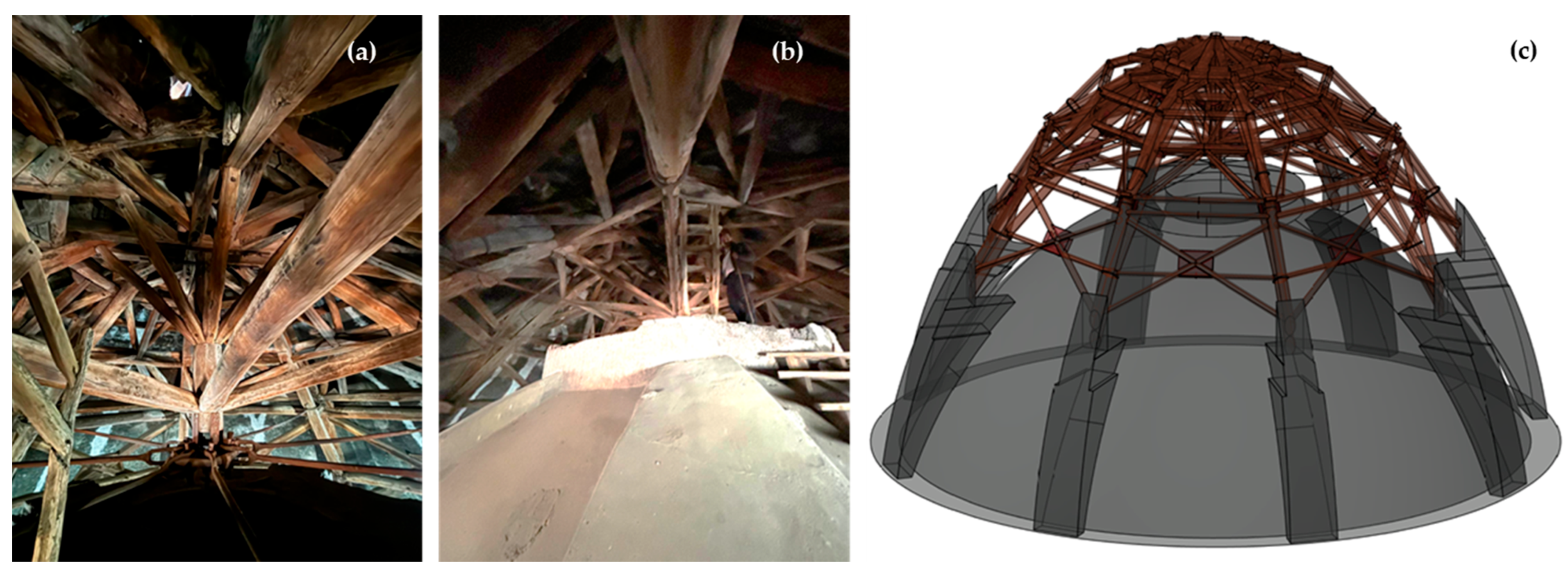
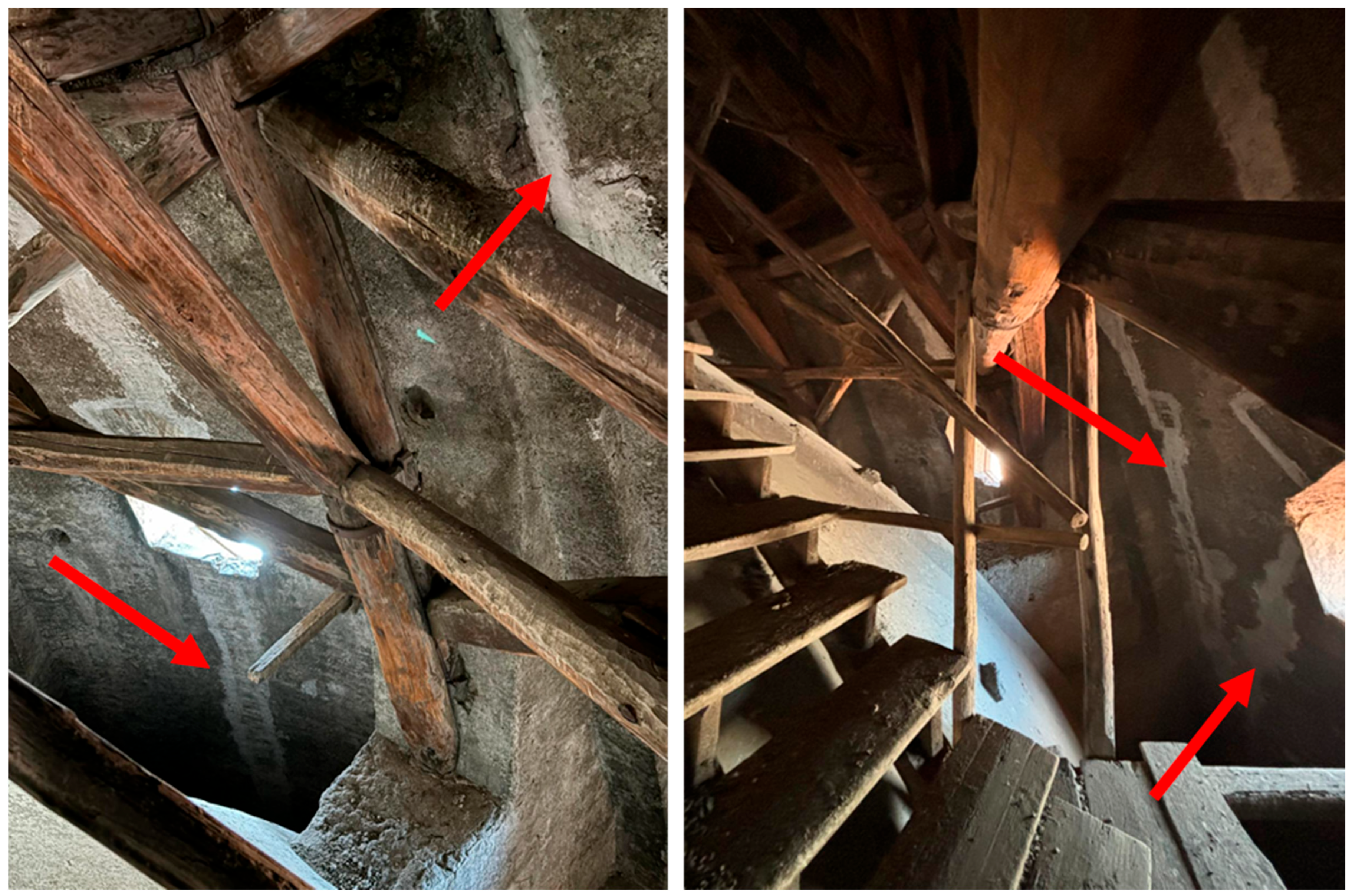
Restoration began in 1724, during which the brick tambour was permanently removed, and the lantern was replaced with a lighter wooden one (covered in lead). An oak umbrella-like structure was also installed between the two shells to reduce the load on the lower dome. The wooden structure, still in place today, represents a complex structural apparatus: a central octagonal kingpost, several orders of rings, eight main struts (each resting on one of the eight buttresses), and eight metal chains converging into an iron ring beneath the wooden kingpost (
Figure 4). Numerous connecting and stiffening elements, such as X-shaped bracing and wooden reinforcement plates, complete the spatial structure.
Figure 4 shows the complex wooden structure [
36] inserted between the two shells following the removal of the first lantern.
Upon completion of the wooden umbrella structure installation, the resulting dome represents a highly sophisticated and unique structural system (
Figure 5).
Nowadays, the upper shell still shows evident signs of 17th-century earthquakes;
Figure 6 highlights them and their reparation with white lime.
4. Calculation Methodologies by Ancient Treatises
The growing interest which has developed in recent years in the study of masonry structures, both as a function of a renewed and strengthened culture of the recovery and restoration of the built environment, and as a function of the scientific deepening of seismic and catastrophic phenomena in general, poses such problems of approach that (in case of safeguard intervention) do not distort the static–mechanical logic with which they were initially conceived and that make them, in any case, capable of withstanding the foreseeable and less foreseeable actions of the many natural and manufactured external forces.
The problem is highly topical because, being inadequate for the wall structures, the hypothesis of the usual elastic calculation commonly applied to steel or reinforced concrete defeats the reference point constituted by the linear variation of the structures. Therefore, the research interest is shifting to the need—supported by various studies over the years—to define a material behaviour model as close as possible to reality so that an appropriate structural verification procedure can be set up.
While the scientific preconditions for the analysis of elastic systems, developed in 1700, were able to constitute the platform of the successive syntheses elaborated by the polytechnic culture of the 1800s, the indications of the illuministic period on the balance of the constructions in masonry have not found an analogous outlet, decaying gradually to the rank of clumsy attempts, often even erroneous, which are now being supplanted by modern calculation methods based on the theory of complexity.
Revisiting today the routes along which the debates on the static and dynamic behaviour of masonry structures have developed means, rather than re-proposing the vast existing bibliography, trying to follow the design and construction process designed and carried out by past engineers, analysing their way of creating the structure empirically and/or scientifically. The process which, in some cases, meant—with simple mechanisms—to presage specific modes of behaviour and certain kinematics of rupture from which congruent design solutions still represent an invaluable wealth of scientific knowledge for the verification project.
Between 1830 and 1840, almost simultaneously and independently, Gertsner (1831) in Germany, Méry (1840) in France, and Moseley (1835, 1838) in England formulated the concept of the thrust-line method, which would become the tool for determining the stability of masonry arches [
41].
Gertsner highlighted the possibility of drawing infinite pressure lines passing through defined points at the key and haunches and introduced the distinction between the pressure and resistance lines.
Moseley applied the principle of minimum resistance to arches, determining the position of the funicular that minimised the thrust [
47].
Méry developed a graphical projection procedure that provides a method for determining the thrust-line so that it is always contained within the middle third of the contact sections between the voussoirs to exclude the onset of tensile stresses [
48].
A more laborious and, therefore, less commonly applied method is that of Durand-Claye [
49] from the late 19th century, which allows for determining, in the key section of a symmetric arch, the area of stability of the structure, that is, the locus of the extremes of the vectors representing the permissible thrusts compatible with both the equilibrium conditions of the structure and the material’s resistance. This method concluded that the collapse mechanism is activated when this area reduces to a point.
This modern approach did not receive its deserved attention and was soon set aside.
The fact that, alongside these theoretical treatises, there was a growing need to apply the studies in practice quickly shifted the focus of the problem from the arch to the dome, which essentially occurred in the field.
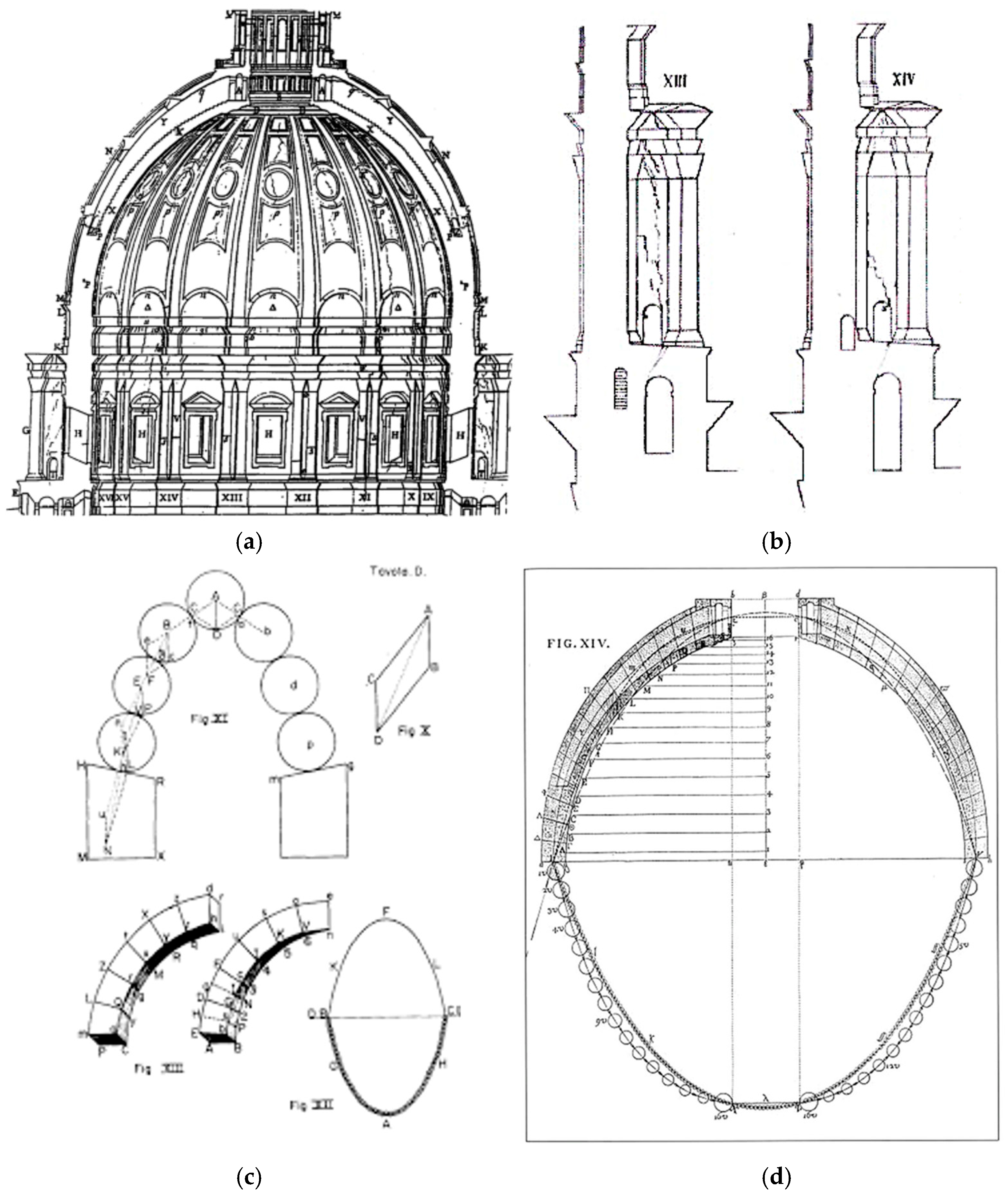
In 1742 and 1743, the dome of St. Peter’s was studied, starting from the cracks that had likely appeared as a result of the already-mentioned violent earthquakes of the 17th century, which sometimes propagated all the way to the Eternal City. Pope Benedict XIV summoned the best experts of the time (including the architect Luigi Vanvitelli, who ultimately provided the decisive solution, a precursor to modern banding). Their studies determined that the cracks were due to a slight settlement of the tambour. The cracks allowed movement, and applying the Principle of Virtual Works made it possible to study the equilibrium of the entire structure [
50].
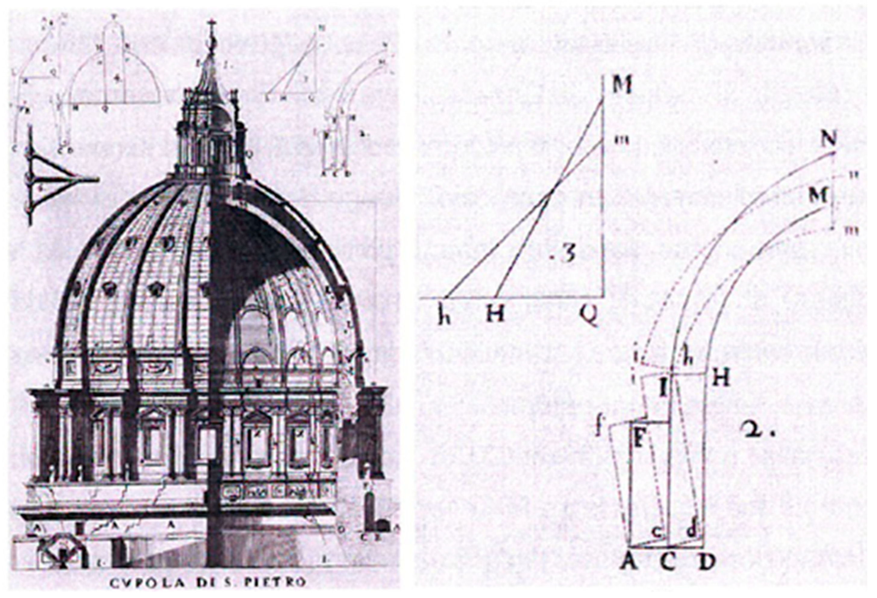
The second fundamental study on domes was conducted by Poleni in 1743 and published in 1748 (
Figure 7) [
51]. Poleni set aside the approach of the three mathematicians and decided to use the theory of the catenary formulated by Gregory and refined by Stirling. Poleni’s brilliant analysis, however, was soon forgotten and only considered again in the second half of the 19th century.
The fact that Poleni [
51] applied the theory of the catenary curve to the section of St. Peter’s (
Figure 7 and
Figure 8), and thus to a real case, as a method for verifying stability, constitutes an early example of scientific rigour [
52].
We do not claim that this brief excursion on the ancient treatises is complete. Still, it aims to highlight the salient points of the evolution of the basic concepts that led to the current definition of “empirical methods”, which are based on the concepts of equilibrium and geometry. These methods, unjustly shelved throughout the nineteenth century and until the second half of the twentieth because they were classified as minor methods for their aptitude to an essentially graphical computation, have been taken up by scholars from 1950 onwards, as already mentioned in the Introduction.
Thus, it can be said that the old treatises form the basis not only for past experiences but also for future ones, since for the protection of historical heritage (a pressing and necessary problem in our region), it is essential that the competencies, the interventions, and any action in this field must be filtered by knowledge of, and respect for, the original concept of the product.
Although such treatises may appear limited when compared to the formalism of modern structural mechanics, their value lies precisely in the clarity of the equilibrium principles they embody. Rather than offering exhaustive predictive tools, they provide essential conceptual frameworks for interpreting the behaviour of historic masonry structures. When applied with critical awareness and adapted to specific case studies, these methods remain highly relevant, particularly in contexts where geometric balance prevails over material resistance.
5. Structural Analysis of the Dome of San Gennaro
In a recent work on the Dome of San Gennaro in Naples by the same authors [
43,
53], the stability of the dome under vertical loads was discussed by analysing the dome as a unified system, employing a combination of methodologies, including limit analysis and the study of reticular wooden structures [
43,
53,
54,
55,
56,
57,
58]. The theoretical framework considers the principles governing masonry structures (modelled as no-tension materials) and timber elements analysed through elastic theory. The focus is defining the interaction between these two structural systems, building upon Heyman’s theories on curved masonry structures [
26].
Considering its materials’ significantly different constitutive properties is necessary for the structural analysis of the dome under study. A decoupled approach has been employed to address these differences effectively. The slicing method was used to analyse the dome using a no-tension material model, and the finite element method (FEM) was used to assess the lattice structure [
33,
48,
49].
It is not easy to determine the precise contribution of the wooden lattice structure because it is not straightforward to determine the proportion of the load the truss bears in advance. An iterative procedure was used to identify a possible equilibrium solution.
This one was afterwards used to analyse the behaviour of the wooden structure.
5.1. The Dome’s Analyses Without the Wooden Structure
Graphically assessing the thrust line of masonry arches and vaults has been the traditional analytical method employed by architects and engineers for centuries [
45,
59,
60,
61]. The equilibrium analysis can be simplified to a two-dimensional problem [
43,
53] by applying the Safety Theorem and assuming no tensile strength.
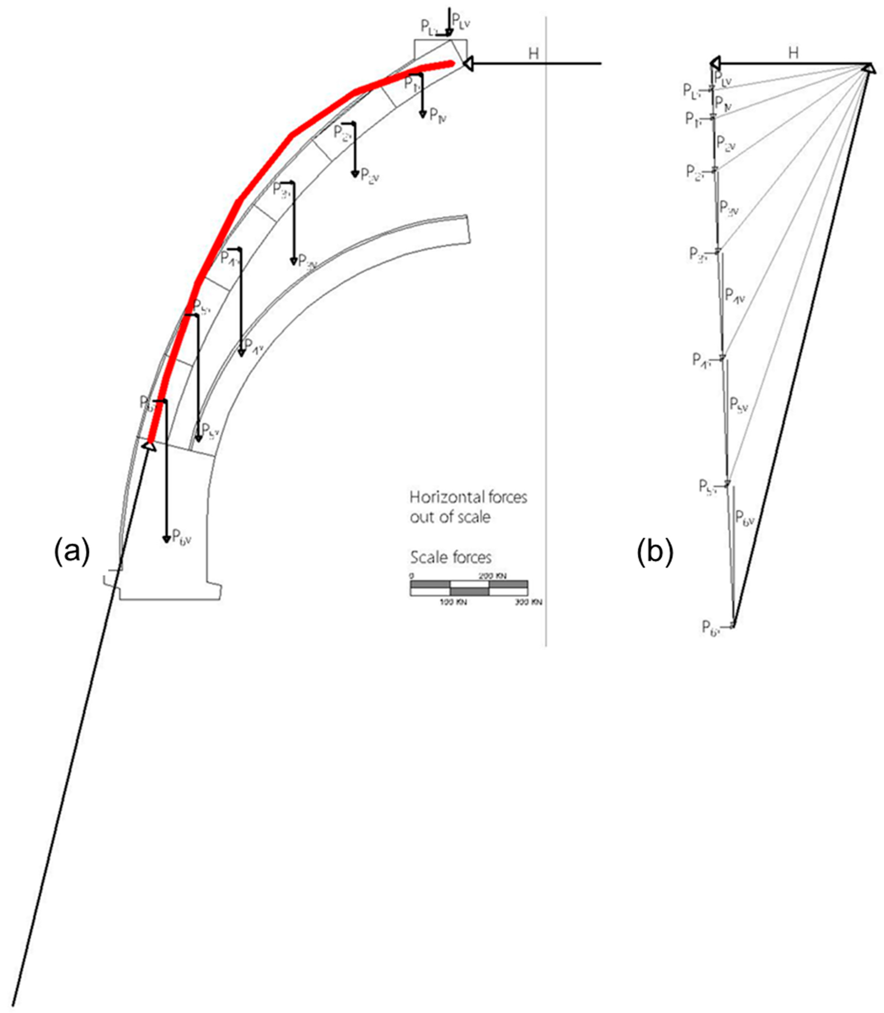
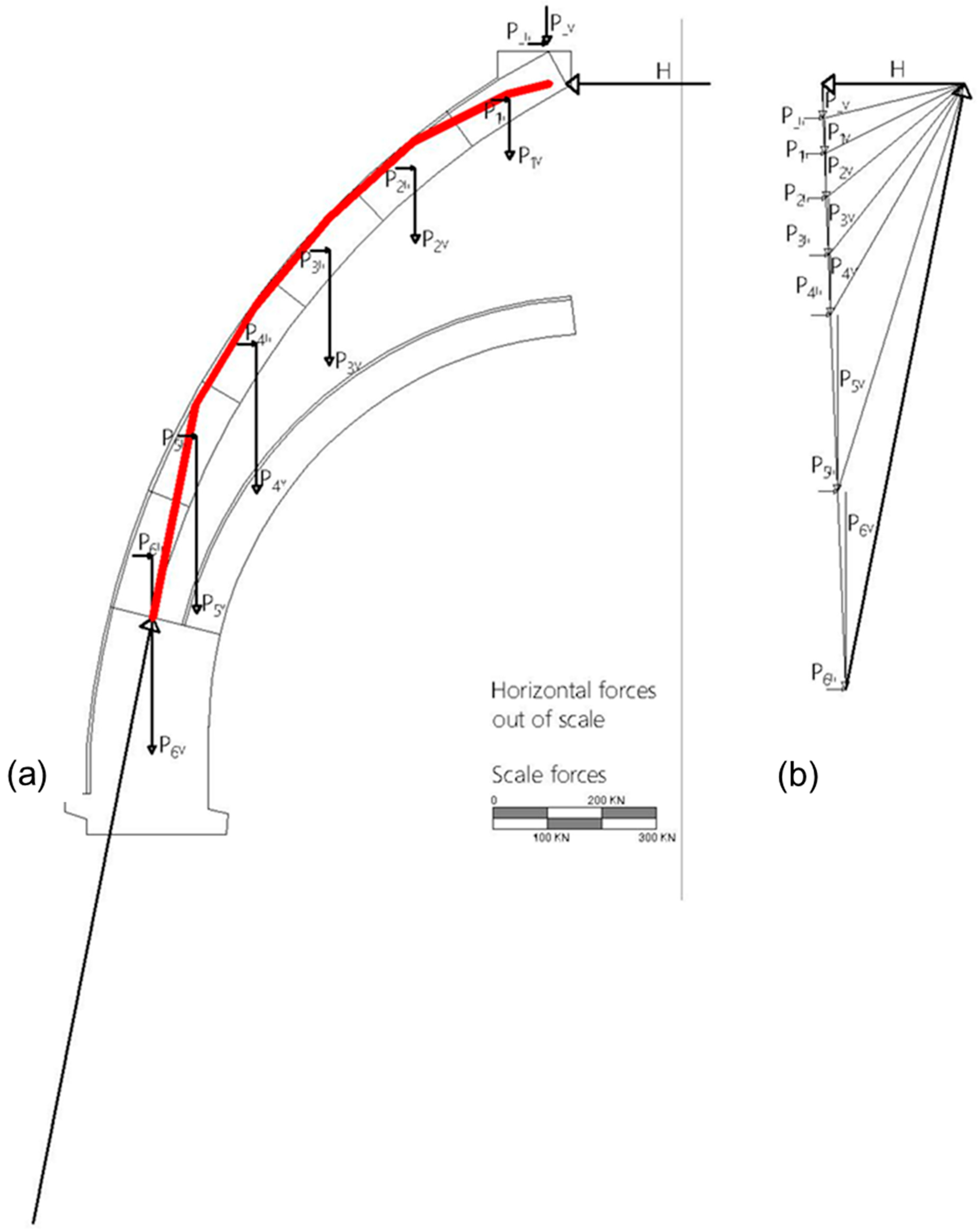
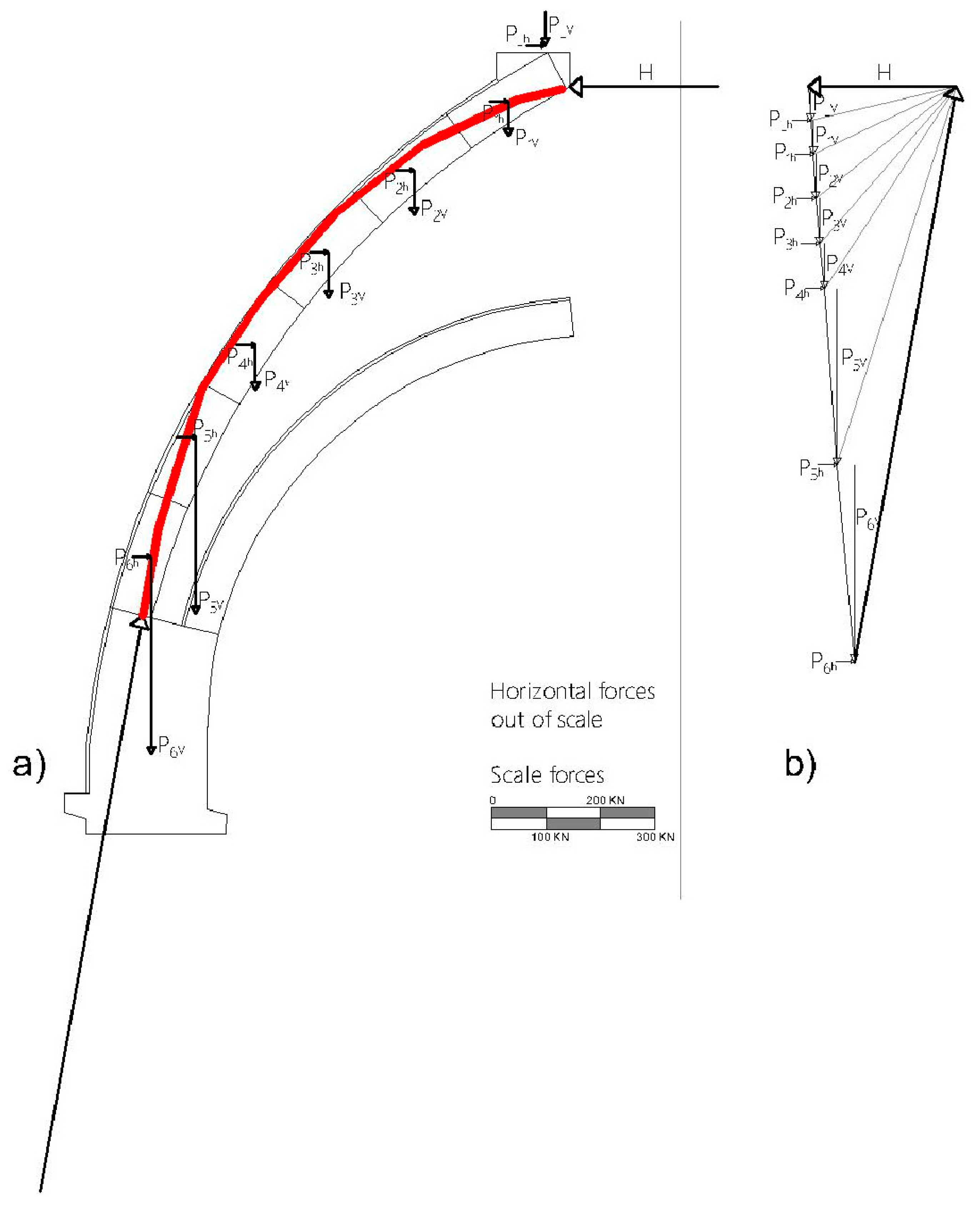
A thrust-line analysis of the dome was conducted to gain a deeper understanding of the structural behaviour of the elliptical upper dome and the contribution of the wooden lattice structure to its stability.
The slicing method [
20,
44] is one of the approaches to studying curved masonry structures that permits a concentrated analysis of a representative portion of the dome. This slice is symmetric and can be examined as an arch.
A representative slice was chosen for the investigated structure and then split into ashlars using the slicing method.
The sum of the contributions of the tuff (W_tuff) and external coating (W_coat) was used to calculate the total weight, P representing the vertical loads.
For the horizontal load, the authors consider two cases:
The thrust line lies outside the masonry thickness in both cases, as shown in
Figure 9 and
Figure 10. The results of this analysis confirm the structural issues and the pattern of cracks and damage observed prior to the installation of the timber framework, which are highlighted in the historical documents [
42,
62,
63,
64,
65,
66,
67,
68,
69,
70]. Therefore, the dome is currently in equilibrium due to the contribution of the wooden structure.
5.2. The Dome’s Analyses in the Presence of the Wooden Structure
Starting from the assumption that the dome is currently in a stable condition—meaning that the thrust line lies within the masonry thickness—it becomes necessary to evaluate the structural contribution of the timber truss. As demonstrated in the previous section, in the absence of this element, the thrust line would fall outside the masonry thickness, thus compromising the stability of the system.
Therefore, an iterative analysis of the thrust line was carried out to quantify the portion of the load borne by the wooden frame. As shown previously, a representative slice was chosen for the investigated structure and then split into ashlars using the slicing method. In this iterative procedure, the percentage of vertical and horizontal loads attributed to each ashlar (masonry) was progressively reduced until the resulting thrust line was completely contained in its thickness.
The steps followed were: (i) assign to each ashlar the reduction percentage; (ii) determine the thrust line graphically; (iii) verify that the thrust line is inside the thickness; (iv) if the thrust line is outside the thickness, change the reduction percentage for the ashlars for which the thrust line is out of the thickness and graphically determine the thrust line again.
The configuration obtained by this process, where the loads associated with each ashlar have its load percentage split between masonry and timber, represents the first balanced solution to guarantee the dome’s static equilibrium.
This procedure was applied both in case (1) and then in case (2).
5.2.1. Case (1) Thrust Line Analysis for Horizontal Forces with an Intensity of 4% of the Weight Loads
At the end of the iterative procedure, the configuration corresponding to the first balanced solution—ensuring that the thrust line remains within the masonry thickness—was identified. The resulting distribution of loads between the masonry and the timber framework is reported below.
Table 2 summarises the vertical actions transmitted to the dome and those absorbed by the wooden structure at specific control points.
Table 3 presents the corresponding horizontal actions, considering the assumed acceleration equal to 4% of the vertical loads, as defined for Case 1.
Figure 11 provides a graphical representation of the system in this equilibrium configuration, showing that the thrust line is fully contained within the masonry thickness, thereby confirming the effectiveness of the structural interaction.
5.2.2. Case (2) Thrust Line Analysis for Horizontal Forces with an Intensity of 9% of the Weight Loads
The same iterative procedure was applied to Case 2 (
Table 4 and
Table 5), which considers increased horizontal actions corresponding to 9% of the vertical loads in accordance with the NTC 2018 provisions. The resulting configuration represents a balanced condition where the thrust line remains within the masonry thickness.
Figure 12 illustrates the equilibrium condition achieved in this case, showing the thrust line entirely contained within the masonry thickness. Also, in this case, despite the increased lateral loads, the structural interaction between masonry and timber proves effective in maintaining stability.
5.3. Wooden Lattice Structure
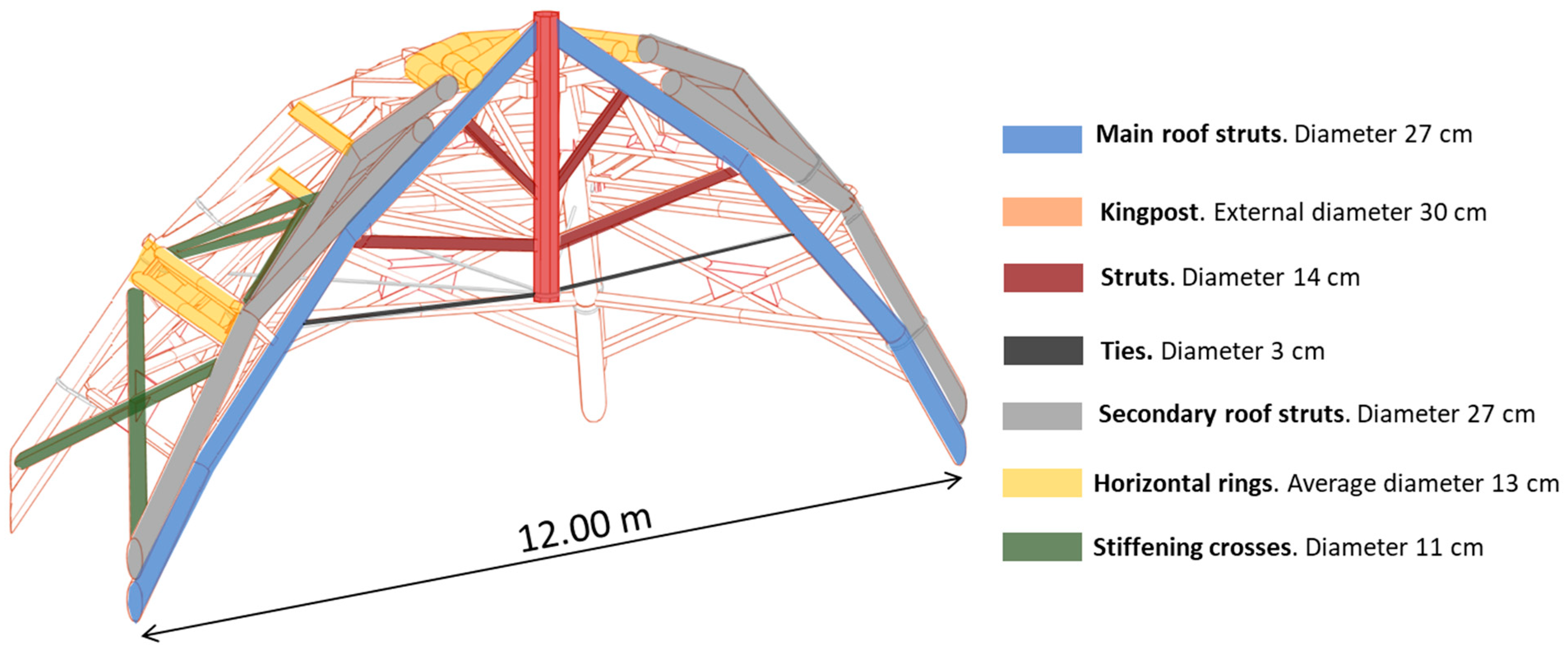
The wooden structure is an elaborate three-dimensional lattice that is meant to help support the upper dome. A network of oak timber elements forms a spatial mesh joined through articulated nodes, resulting in an efficient distribution of loads. The structure’s complexity necessitated a detailed survey as a prerequisite for subsequent structural modelling. The research was conducted through terrestrial and aerial photographic documentation to create a comprehensive illustrative campaign [
53,
54,
55,
56,
70,
71].
MIDAS Gen [
72] software was used to create the structural FEM model representing the lattice structure using beam elements for the wooden components and truss elements for the ties. At its base, the structure was fully constrained. One hundred ninety nodes and 404 elements make up the elastic model.
Due to the historical significance of the structure and the restrictions imposed by the Architectural Heritage Authority, destructive testing on the oak elements could not be performed. However, since the timber components showed no signs of deterioration or structural defects, the mechanical properties were assumed based on the average reference values for hardwood provided in Eurocode 5. For the structural analysis, an orthotropic constitutive model was adopted to account for the anisotropic nature of wood.
Table 6 shows the mechanical parameters adopted.
The FEM model developed for the analysis allowed for the assessment of the structural response of the timber framework under the two loading scenarios described above. In particular, the results are presented in terms of displacements along the global X-axis (horizontal direction) and Z-axis (vertical direction) and axial stresses within the structural elements.
These quantities were evaluated in both load cases, corresponding, respectively, to horizontal forces equal to 4% and 9% of the vertical loads, following the provisions of NTC 2018. The aim is to quantify the influence of the increasing lateral demand on the deformation and internal force distribution within the timber structure.
5.3.1. Case (1) Wooden Structure Analysis for Horizontal Forces with an Intensity of 4% of the Weight Loads
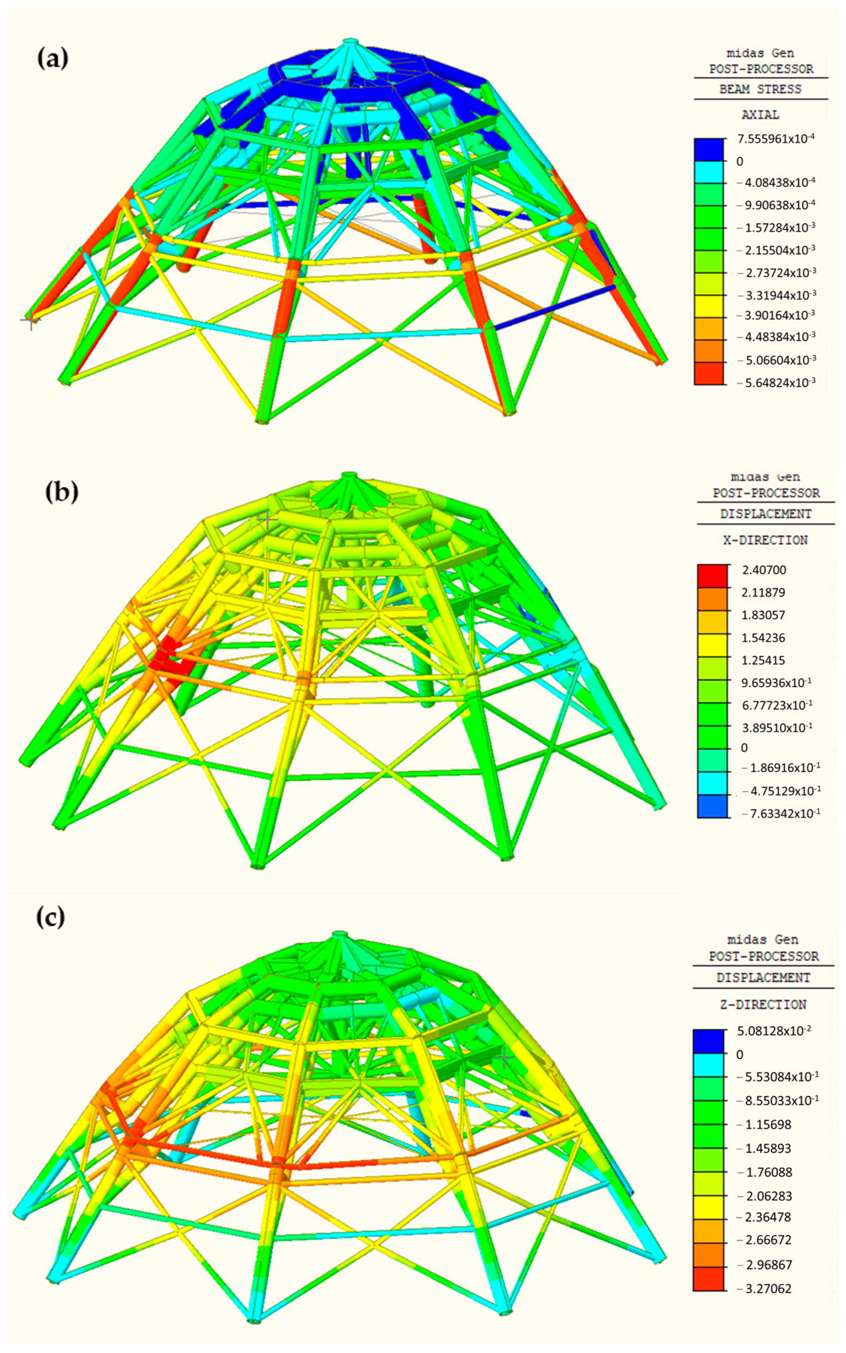
Figure 13 summarises the numerical simulations’ outcomes for the first load case. The analyses were conducted considering the horizontal forces from left to right.
From
Figure 13, it can be observed that the structural response of the timber framework under the loading conditions of Case 1 is generally consistent with the expected behaviour. The axial stress distribution (
Figure 13b) highlights the presence of both compressive and tensile forces, particularly in the lower bracing elements and the intermediate ring, indicating their key role in resisting combined vertical and horizontal actions.
The maximum axial stress recorded in the timber elements is approximately 0.0064 kN/mm2, as the colour scale shows. When compared with the characteristic tensile strength parallel to the grain (fWt,0,k = 0.0125 kN/mm2) and compressive strength (fWc,0,k = 0.045 kN/mm2), this corresponds to approximately 50% of the tensile capacity and only about 14% of the compressive capacity.
These results indicate that the structure operates well within safe stress limits, with no elements approaching their ultimate strength. The internal force distribution appears to be well-balanced, confirming the structural efficiency of the timber framework in its current configuration.
The displacement fields along the global X-axis (
Figure 13b) and Z-axis (
Figure 13c) show that deformations are generally limited, with maximum values located at the structure’s base. This behaviour further confirms the wooden framework’s effectiveness in ensuring the dome’s overall stability under moderate lateral loading conditions.
5.3.2. Case (2) Wooden Structure Analysis for Horizontal Forces with an Intensity of 9% of the Weight Loads
Figure 13 and
Figure 14 present the results of the numerical simulations for the second load case. The analyses were carried out considering horizontal forces applied from left to right.
Figure 14 shows that the structural response of the timber framework under the increased horizontal load conditions of Case 2 (9% of the vertical loads) remains consistent with the expected behaviour, although with higher stress and displacement values compared to Case 1. The axial stress distribution (
Figure 14b) reveals more pronounced tension and compression in the diagonal and lower bracing members, particularly in response to the increased lateral forces.
The maximum axial stress in the timber elements is approximately 0.0106 kN/mm2. Compared to the characteristic tensile strength parallel to the grain (fWt,0,k = 0.0125 kN/mm2), this corresponds to a utilisation rate of approximately 85% in tension. In compression, the highest stress is around 0.0065 kN/mm2, approximately 14% of the characteristic compressive strength parallel to the grain (fWc,0,k = 0.045 kN/mm2).
These values indicate that, under the load scenario of Case 2, the timber elements remain within safe working limits. However, the tensile capacity is significantly more exploited than in the previous case. The compressive utilisation remains low, reflecting a conservative stress distribution.
The displacement fields along the global X-axis (
Figure 14b) and Z-axis (
Figure 14c) show more significant deformations than those observed in Case 1, particularly in the mid-lower regions of the dome and the inclined bracing members. Despite this, the displacements remain within acceptable structural limits, confirming the ability of the wooden framework to ensure equilibrium and overall stability even under more severe lateral loading conditions.
A summary table (
Table 7) is provided below to compare the outcomes of the structural analyses under the two horizontal loading scenarios, both in the absence and presence of the timber lattice structure.
6. Discussion and Conclusions
The Neapolitan domes represent a clear example of how historic architecture demonstrates resilience in the face of seismic challenges. Such architecture is characterised by the repetition of structural components that, although varying in size and exhibiting minor differences in form, are typologically replicated and, therefore, classifiable based on their structural behaviour.
As a macro-element, the dome has been used since antiquity to cover monumental and symbolic buildings, embodying a synthesis of mystical meaning, architectural grandeur, and structural stability.
Exposure to violent earthquakes, particularly during the seismic events of the 17th century, compelled buildings in the Campania region to undergo continuous adjustments in order to adapt to new configurations. Consequently, the cracks that appear within massive masonry structures are not necessarily signs of failure but rather expressions of the adaptability through which these monumental constructions accommodate geometric changes and re-establish equilibrium after a brief period of settlement.
Domes, in particular, tend to develop cracks along the meridians, indicating that the thrust-line within the arch-type geometry—derived from a slicing analysis—has locally reached either the intrados or the extrados of the masonry thickness. This condition does not imply that the structure is close to collapse, provided that at least one thrust-linecan still be identified that remains entirely within the thickness of the arch. In such a case, a new configuration of equilibrium is achieved.
It follows that any impulsive or invasive intervention on historic structures appears reckless and that observation and monitoring are essential during the natural settling phase.
Numerous scholars have addressed these issues, each from their own disciplinary perspective and area of expertise. However, the interest surrounding the Dome of San Gennaro extends beyond the mere presence of a double masonry shell. The majestic wooden structure interconnecting the two masonry layers constitutes a system that lies somewhere between a centring left in place out of fear of catastrophic settlement and a sophisticated seismic mechanism that activates only when necessary—specifically upon the action of horizontal forces. This interpretation is supported by the structural analyses conducted, considering two possible loading cases, which confirm the active role of the timber framework in redistributing forces under seismic loading.
This observation is further supported by historical evidence. It is worth noting that, since the implementation of the wooden lattice structure in the early 18th century, no significant damage to the dome of the Tesoro di San Gennaro has been recorded during subsequent seismic events, suggesting a long-term effectiveness of the intervention.
It is not uncommon to draw parallels between ancient seismic strategies and modern isolation technologies. In this sense, one might hypothesise that the wooden truss connecting the two shells of the San Gennaro dome functions as a seismic actuator within an active control mechanism, capable of elastically absorbing horizontal forces and redirecting them back into the structure in the opposite direction—thereby mitigating the response—precisely because the masonry dome behaves as a rigid element, incapable of elastic deformation.
Based on the analyses conducted, the main findings of this study can be summarised as follows:
The dome of San Gennaro, in the absence of the timber lattice structure, shows significant vulnerability to horizontal loads, with the thrust line falling outside the masonry thickness in both seismic scenarios.
The introduction of the wooden framework restores geometric equilibrium, ensuring that the thrust line remains entirely within the masonry profile under seismic actions of both 4% and 9% of the dome’s weight.
Finite Element Method (FEM) simulations demonstrate that the wooden structure operates well within safe stress limits, particularly in tension, even under increased lateral loads.
The methodological integration of graphical analysis and FEM modelling provides an effective framework for evaluating the structural behaviour of historic domes under seismic loading.
If carried out today using modern materials such as steel or fibre-reinforced composites, a conceptually similar intervention would likely result in a less evocative and considerably more invasive solution.
The subject addressed in this work is of extreme importance since it retraces the path of the recovery of architectural-tonic heritage in full respect of its historical conception and, without wanting to set aside the construction science developed between the second half of 1800 and throughout 1900, it is proposed to find alternative solutions to the theory of elasticity which are more adherent to the mechanical characteristics of the ancient material.
The limit of this approach, which can also be considered as its strength as a challenge open to future research, is evaluating the material’s resistance. This aspect is entirely absent in this case, as it is neglected in favour of all considerations being focused on geometry and balance. In this sense, when the interaction with other materials becomes mandatory, as in the case of San Francesco di Paola or, more generally, in the case of interconnected arches and domes, the methodology runs into simplified models that are often challenging to complete.
The conscious computerisation of the procedures of the ancient treatises and the interaction of flexible patterns with patterns requiring elastic deformities is the problem that will be addressed in future studies.


