Article

Structural Vibration Analysis with Reference to Different Standards

Faculty of Civil Engineering, Wroclaw University of Science and Technology, Wybrzeże Wyspiańskiego 27, 50-370 Wrocław, Poland
Buildings 2025, 15(11), 1951; https://doi.org/10.3390/buildings15111951
Submission received: 14 May 2025 / Revised: 29 May 2025 / Accepted: 3 June 2025 / Published: 4 June 2025

Abstract

:
The necessity for appropriate control of the surrounding area of the construction site is especially imperative during geotechnical work, when a high amount of energy is transferred to the ground. To ensure the safety of structures in the vicinity of the works, vibration sensors are used to monitor the area. Moreover, increased vibration levels can be reduced by adjusting the applied technology, specifically Rapid Impact Compaction. This paper sets out a number of standards for the assessment of the impact of vibrations on structures near the construction site. Furthermore, this paper presents several case studies that demonstrate the effectiveness of vibration measurements in the appropriate adaptation of technology, with the objective of reducing the impact of vibrations on the surrounding area. During the conducted observations, vibration velocities ranging from 0 to 5 mm/s were recorded. As a result, a technological adjustment was recommended in a particular instance due to the occurrence of vibration velocities that surpassed the established limits as outlined in DIN standard specifications.

1. Introduction—Basic Issues Related to Vibration Control

The advancement of civil engineering in recent years has led to an increase in the construction of buildings in geotechnically complex and densely built-up areas. The execution of construction projects in such conditions frequently necessitates the implementation of specialised geotechnical technologies. These technologies are designed to adapt the construction process to a wide range of conditions, ensuring its viability in diverse environmental contexts. Such technologies are highly invasive, affecting the surrounding environment due to the energy transferred to the ground. Consequently, a significant number of building structures in the vicinity of the construction area may be impacted, and it is imperative to implement the meticulous monitoring of the surrounding structures during the execution of the work. This enables the observation of the detrimental effects of geotechnical works in real time, facilitating the adaptation of technologies to external conditions or the transition to more environmentally friendly technologies through technology calibration [1,2] or vibration barriers [3].

1.1. Codes of Practice and Vibration Assessment Regulations and Recommendations

One of the most common methods of controlling the surrounding area is monitoring the vibrations of structures in the vicinity of ongoing construction work [4]. Several authors have made attempts to provide recommendations for vibration control [5,6,7], referring to numerous international codes of practice [8,9,10,11,12,13]. By placing sensors at sensitive locations, the situation on site can be accessed in real time [14]. The sensor can measure either velocity or acceleration displacement in the three directions: x, y, and z. The resulting values are presented on a velocity or acceleration diagram, depending on the frequency of the vibration. In addition, vibration monitoring can be useful in adjusting geotechnical technology to the situation on the construction site.
However, interpretation of the results requires the application of at least one of the standards describing vibration measurements. As the criteria given in codes listed above are not fully coherent, some experience should be gathered for the proper evaluation of the monitoring results.

1.2. Experiences of Vibration Monitoring in the Case of Various Objects and Grounds

The transmission of waves during vibrations in geotechnical works is influenced by soil type, density, and degree of saturation. Coarse-grained soils have been shown to exhibit higher wave velocities. This phenomenon can be attributed to the soils’ granular structure and high permeability. Fine-grained soils exhibit reduced wave velocities, attributable to their cohesive nature and diminutive particle sizes. Furthermore, denser soils exhibit higher stiffness and faster wave propagation due to lower compressibility, while looser soils allow for greater vibration amplitude and slower wave velocities. Finally, it has been established that dry soils facilitate faster and clearer wave transmission, whereas partially saturated soils display complex, nonlinear behaviour due to the interaction between air and water in the pores. Fully saturated soils can exhibit reduced shear strength and wave velocity under undrained conditions due to increased pore water pressure, with loose saturated sands being especially susceptible to liquefaction [15,16].
Building structures may be sorted depending on their vulnerability on ground-transmitted vibrations. Most codes and regulations use the following gradation: architectural merit, residential area, light commercial, and heavy industrial and buried structures [11]. Specific recommendations are given for weir constructions [7,17], buildings [18,19], and soils [15,16]. Both structure and underlaying ground may be affected by vibrations. The impact on the structure is direct and causes damage depending on the intensity (measured velocity) of the vibrations. On the contrary, the impact on soils leads to the compaction of granular soils (sand, gravel) and the weakening of cohesive soils (silt, clay). This impact causes uneven settlements and finally affects the structure in a longer period, even long after the source of the vibrations is not active. Very useful recommendations concerning safe distances for structures and piling technologies were given in the work in [16].

1.3. Analysis of Most Harmful Geotechnical Technologies

Sources of vibrations may be ranked according to potential harmfulness. Concerning piling works using impact driving [20], Franki piles are considered to have the biggest affect on the neighbourhood [17,18]. Other methods based on impact driving used for soil improvement like Dynamic Compaction (DC) [21] and Rapid Impact Compaction (RIC) [16,22] also require cautious attention to be paid to them because of the relatively wide zone of influence and high amplitudes.
In the case of harmonic vibrations, heavy vibrators used for sheet pile driving seem to be the most harmful [23,24,25]. Vibratory rollers, due to a shallow source of transmission, may also “produce” harmful Rayleigh (surface) waves [26,27].

1.4. Attempts to Numerically Model Ground-Transmitted Vibrations of Various Sources

The development of geotechnical software made it possible to model and analyse the impact of vibrations of different sources without excessive field testing [28,29,30]. However, field testing still seems to be the mandatory way of calibrating numerical models. That is why most of the literature is based on both modelling and field testing [31,32,33].

1.5. Monitoring, Technology Calibration, Vibration Control, and Possible Mitigation of Impact

All the issues listed in this subsection’s title are still hot subjects in the literature. Recent review papers [34,35] have focused on vibration screening techniques [34] and “Integrated Life Cycle Design Principles” [35]. The development of vibration mitigation techniques by means of anti-vibration pile barriers [36,37] and open trenches [38,39] is the subject of current progress. Also, the reuse of spoil material like Waste Rubber Chips for the filling of wave barrier trenches seems to be a sign of progress [40].

1.6. Knowledge Gap and the Present Study’s Contribution

Despite the extensive literature on the subject of the effects of vibrations, such as construction activities, on the surrounding environment, the methods of vibration measurement, and ways of interpreting the resulting data, there remain significant gaps in the complex part combining these issues.
The present study demonstrates the efficacy of vibration measurements in calibrating geotechnical technologies, which have the potential to be highly invasive to surrounding structures, with reference to the relevant standards. A distinctive feature of this work is the demonstration of how selection technology can be adjusted in real time to reduce the impact of vibrations on surrounding buildings, as evidenced by the presented case studies. The methodology delineated herein has the potential to enhance the efficacy of geotechnical methodologies while concurrently ensuring the integrity of structural safety.

2. Vibration Classifications

In order to ascertain whether vibrations are detrimental to the measured structure, various classifications are proposed in order to assess the impact of measured vibrations. A comparison of different standards can be found in [5,6]. The most widely adopted methods include German standard DIN 4150-3:1999-02 [11], British BS 5228-2 [12], and French Circulaire 23/07/86 [13]. The examples of vibration measurement results in relation to specific standards are drawn from SVANPC++, specifically for the purposes of this paper. SVANPC++ ver. 3.5.2 is a software programme used to analyse vibrations measured by SVANTEK devices [41].

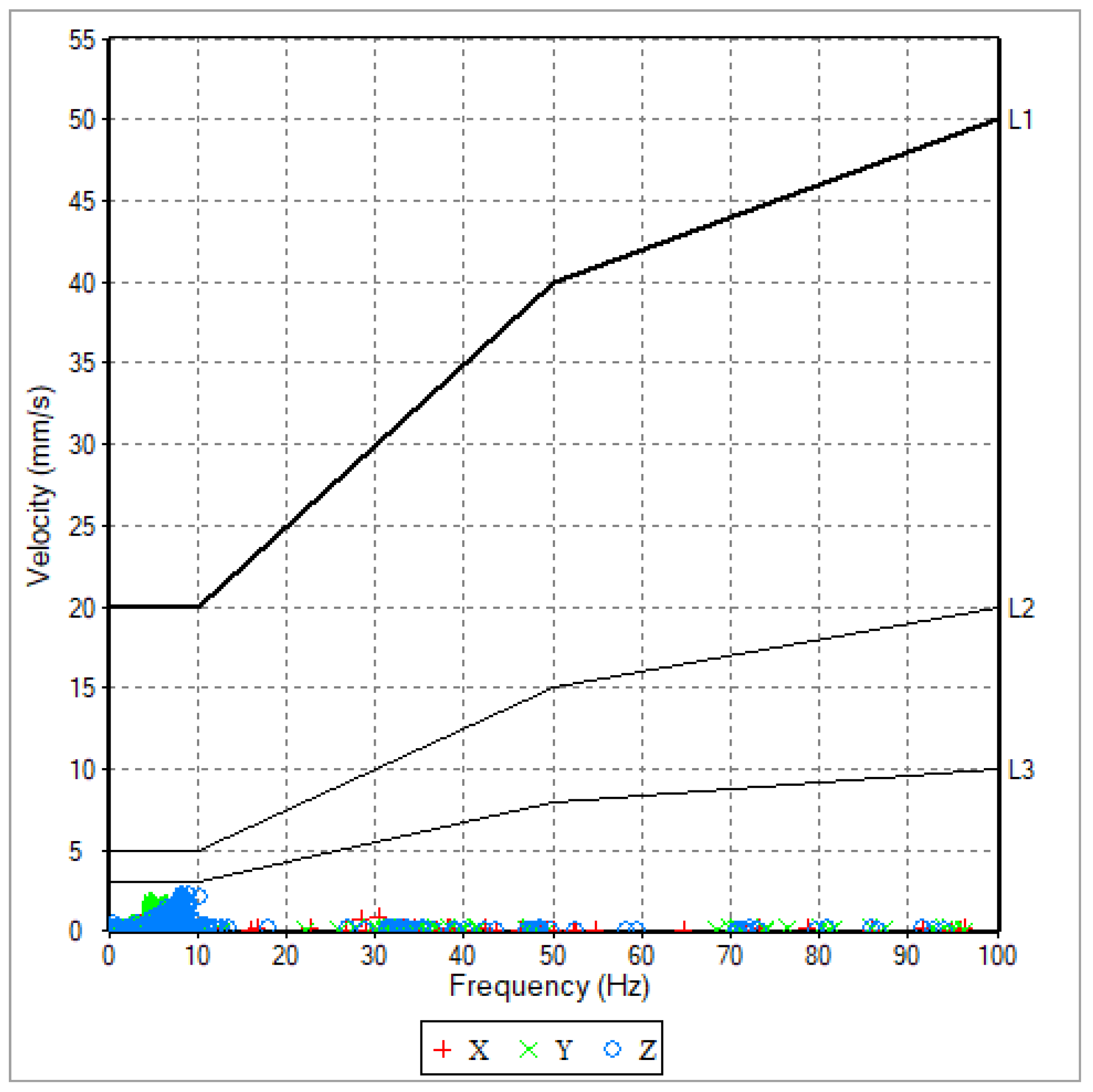
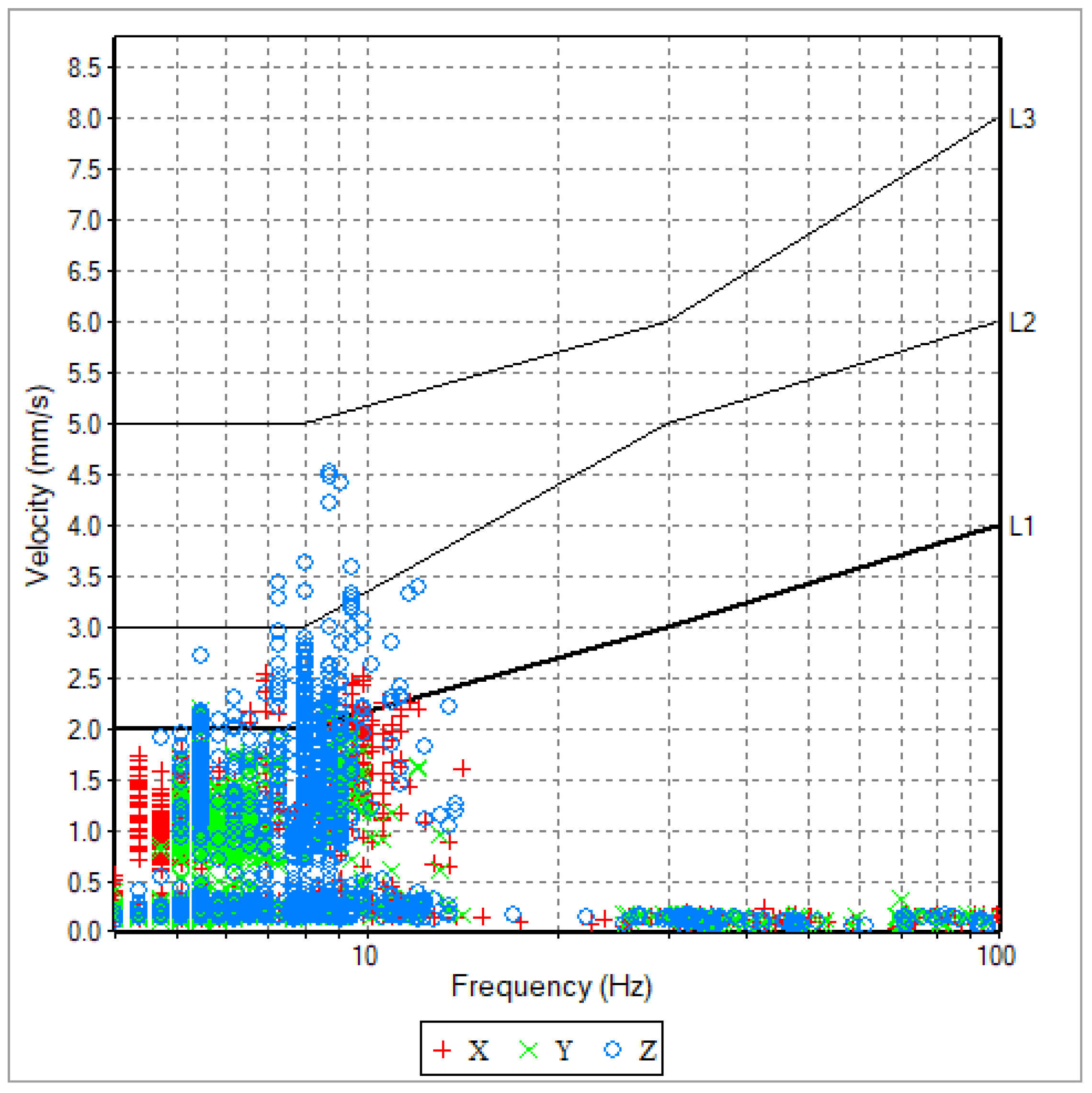
2.1. DIN 4150-3:1999-02 [11]

The harmful nature of vibrations in this standard is determined by their velocity and frequency [11]. The results of the vibrations are represented in a chart of vibration velocities in relation to their respective frequencies (Figure 1). The delineation of zones is conducted in accordance with the structural sensitivity to vibrations. Vibration damage is represented schematically as a line according to three zones: Zone I is defined as industrial buildings, Zone II as residential buildings, and Zone III as buildings that are particularly sensitive and historic [11]. The vibration of each group of buildings should not exceed the line marked behind the diagram, with the result that the permissible speeds vary according to their frequency [11]. Low-frequency vibrations (e.g., RIC) are more detrimental to structures; therefore, the vibration velocity values that are considered harmful are lower. As the frequency of the vibration increases (e.g., vibrating sheet piling), the allowable vibration velocities are higher; as for higher frequencies, the harmfulness of the vibration is greater for higher velocities.
The classification presented here pertains to short-term measurements; for long-term vibrations, the requirements are much more rigorous [11]. The intensity of the vibrations can be significantly amplified along the height of buildings; therefore, measurements made on floors should also be verified with relevant codes and with the allowable values for human exposure to vibrations as described in DIN 4150-3:1999-02 [11] and in [6].

2.2. BS 5228-2 [12]

The BS 5228-2 standard provides guide values (for velocities in the range of 0–15 and 15–50 mm/s) for short-term vibrations, which are measured at the foundation level [12]. Measured vibrations are also considered in terms of two parameters: vibration velocity and frequency. The values obtained are then plotted on a velocity/frequency diagram. In order to ascertain the range of permissible vibration, this is considered in relation to two lines, which define three zones depending on the type of building [12]. Line 1 delineates the permissible vibration levels for framed and reinforced buildings as well as industrial and large commercial buildings. Line 2 delineates the vibration parameters that are permissible for light-framed and unreinforced buildings as well as for residential and small commercial buildings. The maximum component of the vibration velocity at the foundation level due to dynamic loads is then compared with the established criteria [12]. Lines are used to indicate the limit above which cosmetic damage, such as the formation of cracks in walls or ceilings, may occur. It is anticipated that damage will be reduced by a factor of two when the guide value is doubled, and by a factor of four when the guide value is increased fourfold [12]. The results of the vibration measurement in terms of the BS 5228-2 standard are presented in Figure 2.
For long-term vibrations or excitation from building resonance, the acceptable vibration level should be reduced by a minimum of 50% [12].

2.3. French Standard Circulaire 23/07/86 [13]

The results of the vibrations are presented in terms of velocity and frequency. The measurement is based on the peak values of the vibration velocity in the X/Y/Z directions, with a frequency range of between 4 and 150 Hz [13]. In accordance with DIN 4150-3, the measurement of vibrations is to be conducted in relation to three lines, which delineate the permitted vibrations for each construction type. Line 1 delineates constructions that are particularly sensitive, line 2 delineates constructions that are sensitive, and line 3 delineates constructions that are insensitive (Figure 3). The limit value chart differs according to the duration of the vibrations [13].
For the purpose of evaluation, the maximum of the three peak values and its main frequency are the relevant parameters [13]. The primary distinction between this standard and DIN 4150-3 and BS 5228-2 lies in the recommendation that the sensor should be situated not only on the foundation of the building but also on the floor during measurement [13].

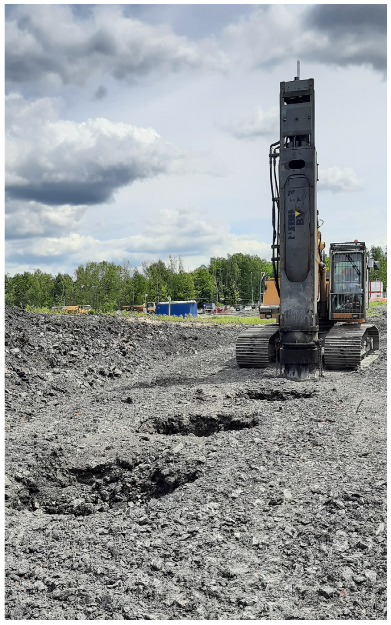
3. Rapid Impact Compaction Technology

Rapid Impact Compaction (RIC) (Figure 4) is a soil compaction method that utilises a hydraulic hammer with a weight range of 5–12 tonnes and a diameter range of 0.8–1.5 m. The hydraulic hammer descends from a low height, thereby achieving the desired compaction. The implementation of this method facilitates the transfer of energy into the deeper layers of the ground, thereby inducing compaction in the looser soil deposits up to a depth of 5–6 m below ground level [2,5].
During the process of ground compaction, energy is released within the soil, thereby generating vibrations in the immediate surrounding environment. Properly applied vibration monitoring controls the effect of vibrations on the structures. In view of the findings derived from the analysis of vibration measurements, it is possible to adjust the level of energy applied to the ground to ensure that it corresponds to the magnitude of the vibration level that has been obtained. Consequently, in instances where the vibration level in the monitored building is excessively high, its reduction can be achieved through a reduction in the energy delivered to the ground by the hammer. This can be accomplished by either decreasing the height of the hammer drop or by transitioning to a smaller hammer size. Consequently, the process of monitoring enables the technology to be calibrated to existing conditions.

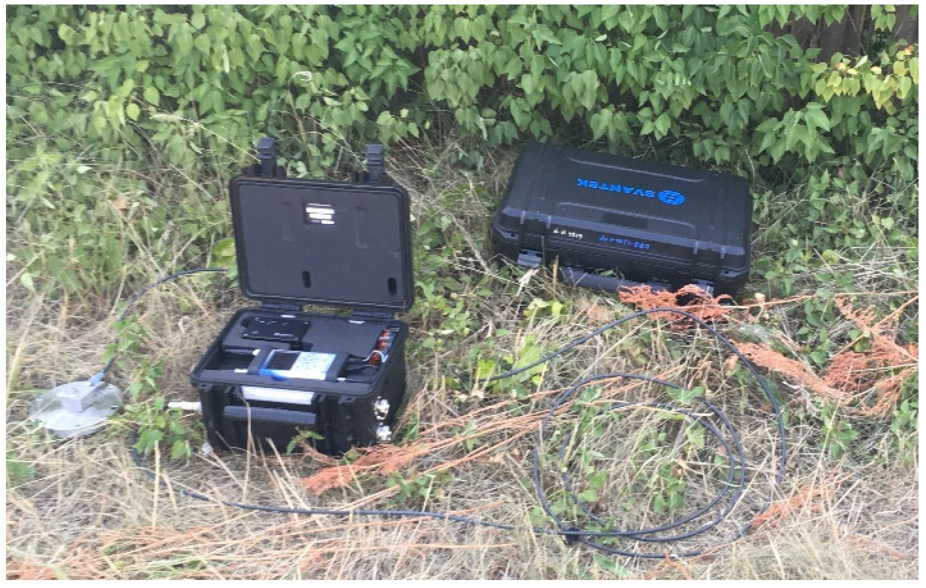
4. Methodology of Vibration Measurements

Vibration monitoring is performed with the Svantek SVAN 958A sensor, which has a sampling frequency of 3000 Hz [41]. The SVAN 958A is a digital signal analyser comprising four channels, with a frequency range of 0.5 Hz to 20 kHz. It is equipped with a class 1 sound level metre that conforms to the IEC 61672-1:2002 standards, as well as a vibration metre that meets the ISO 8041:2005 specifications. The apparatus is equipped with four channels, each of which facilitates parallel measurements with filters that are defined independently. The RMS detector time constants are configurable for each individual channel. Furthermore, the SVAN 958A instrument can perform advanced frequency analysis in conjunction with the metre mode, facilitating real-time 1/1 or 1/3 octave analysis, encompassing statistical calculations and FFT analysis, and incorporating cross spectra. The building vibration mode of the apparatus offers simultaneous velocity and acceleration measurements, with the automatic indication of a dominant frequency in accordance with the DIN 4150-3:1999-02 [11], BS 5228-2 [12], and Circulaire 23/07/86 [13] standards.
The sensor has the capacity to measure either velocity or acceleration displacement in the three directions (x, y, z). During the measurement process, maximum velocity values greater than 0.1 µm/s were observed at the sensor at 15 s intervals. The device displays measurement results from 15 s intervals on the device screen, enabling the magnitude of vibrations to be monitored in real time as work progresses. The resulting values are presented on a velocity or acceleration diagram, depending on the frequency of the vibration. The monitor station is presented in Figure 5.

5. Application of Vibration Measurements to the Calibration of the RIC Method (Field Case Studies)

The necessity of close-neighbour vibration monitoring when utilising the RIC technique is demonstrated by the presentation of two case studies, which illustrate vibration measurement results from two disparate sites.

5.1. First Case

Firstly, an analysis of the vibration monitoring of a two-storey brick-built house is presented (Figure 6). In the vicinity of the building, a compaction of the soil under the design road was proposed using the RIC method. Due to the close proximity of the works conducted, the building was monitored during the compaction process.
The site was originally composed of organic soil, with a depth of 2–4 m beneath the soil surface. This soil was replaced by a well-grained, loose, dry medium sand that was subsequently compacted to the required level of compaction. The compaction of the soil was achieved by means of an excavator, which was equipped with an 8-tonne hydraulic hammer. The excavator was elevated from a height of 80 cm, at a rate of approximately 40 blows per minute. The hammer struck a steel footplate of 100 cm and had a diameter of 60 cm. As demonstrated in Figure 7, the outcomes of the vibration measurements illustrate the fluctuations in vibration velocity over time, with specific periods highlighted where no compaction occurred.
During vibration monitoring, soil compaction was conducted at the same location employing two footplates. The first footplate had a diameter of 100 cm, while the second had a diameter of 60 cm. Consequently, the influence of each footplate on the vibration results of the monitored structure was monitored. The interpretation of the vibration monitoring results, i.e., the determination of their harmfulness to the surroundings, is only possible by relating the obtained results to the vibration classification presented in Chapter 2. The DIN [11], BS [12], and Circulaire [13] standards were proposed with the objective of determining the harmful nature of such vibrations. The results of the vibration measurements in relation to each standard are presented in Figure 8, Figure 9 and Figure 10. In each figure, (a) presents the level of vibration with a 100 cm footplate, and (b) presents the level of vibration with an 80 cm footplate.
Figure 8, Figure 9 and Figure 10 illustrate the measurement points from the complete vibration monitoring, presented as a function of vibration velocity versus frequency. Furthermore, limit lines have been delineated on each graph to represent the permissible values for each structure type. The key data for interpreting the graphs are the results of vibrations of the structure from soil compaction using the RIC method, defined by a frequency range of 0–15 Hz. The vibration velocity values within this frequency range are observed to occur between 0 and 5 mm/s. Vibration velocity is found to be greater in cases of a larger footplate. These values exceed the limit values for sensitive buildings, as evidenced by DIN [11] and Circulaire [13]. However, in accordance with the BS [12] standard, the vibrations were well below the established limits. After changing the footplate to a smaller size, vibration velocities did not exceed the set standards. In addition, other measurement points indicative of higher-frequency vibrations from alternative sources are observed; however, these are found to be below 1 mm/s. Consequently, these vibrations have no effect on the construction.

5.2. Second Case

The second case study focuses on the measurement of vibrations in an existing warehouse hall during the impact compaction of the ground for the construction of an adjacent hall (see Figure 11). In this case, the sensor was positioned within the hall on the floor. The compacted layer was identified as a post-construction anthropogenic soil, characterised by the presence of post-mining waste, and classified as non-cohesive. The compaction of the soil was achieved through the utilisation of a machine that possessed parameters analogous to those of the first case, with a footplate diameter of 100 cm being employed.
As with the first case, vibration monitoring was also conducted using the Svantek SVAN 958A device. As demonstrated in Figure 12, the variation in vibration velocity over time for the monitored hall is illustrated. Furthermore, the results of the vibration measurements in relation to DIN, BS, and Circulaire are presented in Figure 13, Figure 14, and Figure 15, respectively.
In this case, the vibration velocity values within the frequency range of 0–12 Hz were attributed to impulse compaction, while those in the remaining range were attributed to alternative vibration sources. The vibration velocities for impulse compaction were found to be within a comparable range to the initial case of 0–5 mm/s. Nonetheless, in this case, the monitoring of different types of buildings (warehouse hall) resulted in the conclusion that the vibrations are not detrimental to the structure. Consequently, no alterations were made to the compaction method.

6. Discussion of Presented Results

As demonstrated by the figures, it is essential to undertake a thorough investigation of the vibration measurement analysis in relation to the established standards. The analysis of the results in relation to a specific standard may reveal over-vibration values, while an analysis against a different standard may indicate values within the acceptable range.
In the initial case study, an examination of the outcomes in relation to DIN standards (see Figure 8) reveals that the modification of the footplate led to a reduction in the values of vibration velocities. This decision was primarily influenced by the suboptimal technical condition of the monitored building. For the 100 cm footplate, velocity values were found to exceed the established limit for sensitive and historical buildings. Following the modification of the footplate, the vibration velocities attained a level that was within the established safety parameters for this limit. A similar phenomenon was also observed in relation to the Circulaire standard. In comparison, the BS standard adopts a more liberal approach to this issue, as vibrations both before and after the change in the compaction hammer were deemed to be within acceptable parameters. In the second case, a similar phenomenon was observed. However, it was determined that changes in technology were not necessary due to the different type of measured construction (steel hall in good condition).
To summarise, the employed standards vary in terms of the level of vibration permissibility. The measurement of vibrations is subject to different limit values. As demonstrated by the provided examples, the DIN standard [11] is the most conservative, as it has vibration limits at a lower level. Circulaire [13] demonstrates a marginally more liberal stance, with the BS standard [12] representing the most liberal approach.

7. Conclusions

The paper presents the application of sensors to measure the vibrations of buildings surrounding ongoing construction work. The following conclusion can be made based on the conducted research:
  • The paper demonstrated the effectiveness of structural vibration monitoring in calibrating geotechnical technology, ensuring the safety of surrounding constructions.
  • The assessment of vibration impact can be conducted in accordance with the established standards systems, which delineate permissible vibration levels in consideration of the specific characteristics of the monitored structure.
  • Nonetheless, standards are intended to serve as guidelines; the ultimate responsibility for the safety assessments rests with the individual interpreter and their ability to expert judgement.
  • It is evident that this method of adapting technology in order to reduce the impact of vibration can also be applied to other technologies. For instance, in the context of the installation of sheet pile walls, the frequency of the vibration hammer can be modified.
  • Furthermore, the calibration of numerical models can be enhanced through the utilisation of vibration measurements, thereby ensuring a more precise alignment with actual soil conditions.
  • In addition to technological changes, alternative methods of vibration reduction (described in Section 1.5) could be employed. However, the implementation of any such solution would necessitate appropriate calibration to ensure the accuracy of the reduction in vibration measurements.
Advancements in foundation technologies are expected to result in an increased application of more intrusive methods in the field of geotechnical engineering. Consequently, the role of vibration monitoring is anticipated to become significantly more substantial in the future.

Funding

This research received no external funding.

Data Availability Statement

The original contributions presented in this study are included in the article. Further inquiries can be directed to the corresponding author.

Conflicts of Interest

The author declares no conflicts of interest.

References

  1. Rybak, J.; Pieczynska-Kozlowska, J. Vibration monitoring as a tool for a calibration of geotechnical technologies. In Proceedings of the 14th International Multidisciplinary Scientific Geoconference (SGEM), Albena, Bulgaria, 17–26 June 2014; pp. 1043–1050. [Google Scholar]
  2. Dobrzycki, P.; Kongar-Syuryun, C.; Khairutdinov, A. Vibration reduction techniques for Rapid Impulse Compaction (RIC). J. Phys. Conf. Ser. 2019, 1425, 012202. [Google Scholar] [CrossRef]
  3. Meng, L.; Cheng, Z.; Shi, Z. Vibration mitigation in saturated soil by periodic pile barriers. Comput. Geotech. 2020, 117, 103251. [Google Scholar] [CrossRef]
  4. Svinkin, M.R. Tolerable limits of construction vibrations. Pract. Per. Struct. D Constr. 2015, 20, 1–7. [Google Scholar] [CrossRef]
  5. Herbut, A.; Rybak, J. Guidelines and recommendations for vibration control in the case of rapid impulse compaction. In Advances and Trends in Engineering Sciences and Technologies II, Proceedings of the 2nd International Conference on Engineering Sciences and Technologies, ESaT 2016, Tatranské Matliare, Slovakia, 29 June–1 July 2016; CRC Press: Boca Raton, FL, USA, 2017; pp. 761–766. [Google Scholar]
  6. Herbut, A.; Jakubczyk-Galczynska, A.; Wyjadlowski, M. Vibration monitoring of structures in the light of the Polish and international requirements. Stud. Geotech. Mech. 2023, 45, 209–220. [Google Scholar] [CrossRef]
  7. Wyjadlowski, M. Methodology of dynamic monitoring of structures in the vicinity of hydrotechnical works-selected case studies. Stud. Geotech. Mech. 2017, 39, 121–129. [Google Scholar] [CrossRef]
  8. ISO 4866:2010; Technical Vibration and Shock Vibration of Fixed Structures—Guidelines for the Measurement of Vibrations and Evaluation of their Effects on Structures. International Organization for Standardization: Geneva, Switzerland, 2010.
  9. PN-B-02170:2016-12; Ocena Szkodliwości Drgań Przekazanych Przez Podłoże na Budynki. Polish Committee for Standardization: Warsaw, Poland, 2016. (In Polish)
  10. SS 02 52 11-1999; Vibration and Shock–Guidance Levels and Measuring of Vibrations in Buildings Originating from Piling, Sheet-Piling, Excavating and Packing to Estimate Permitted Vibration Levels. Swedish Institute for Standards: Stockholm, Sweden, 1999.
  11. DIN 4150-3:2016-12; Vibrations in Buildings–Part 3: Effects on Structures. German Institute for Standard: Berlin, Germany, 2016.
  12. BS 5228-2:2009; Code of Practice for Noise and Vibration Control on Construction and Open Sites—Part 2: Vibration. BSI: London, UK, 2009.
  13. Circulaire du 23/07/86 Relative Aux Vibrations Mécaniques Émises dans L’environnement par les Installations Classées pour la Protection de L’environnement. (In French). Available online: https://aida.ineris.fr/reglementation/circulaire-230786-relative-vibrations-mecaniques-emises-lenvironnement-installations (accessed on 4 May 2025).
  14. Herbut, A.; Rybak, J.; Brząkała, W. On a sensor placement methodology for monitoring the vibrations of horizontally excited ground. Sensors 2020, 20, 1938. [Google Scholar] [CrossRef]
  15. Wyjadlowski, M.; Zieba, Z. Impact of Dismantled Sheet Pile Vibration on Cohesive Soil Parameters. IOP Conf. Ser. Earth Environ. Sci. 2020, 609, 012062. [Google Scholar] [CrossRef]
  16. Dobrzycki, P.; Ivannikov, A.L.; Rybak, J.; Shkodkina, V.O.; Tyulyaeva, Y. The impact of Rapid Impulse Compaction (RIC) of large non-cohesive material deposits on the surrounding area. IOP Conf. Ser. Earth Environ. Sci. 2019, 362, 012132. [Google Scholar] [CrossRef]
  17. Wyjadłowski, M.; Sawicki, E. Study of impact sheet pile and Franki NG pile driving on weir construction. J. Phys. Conf. Ser. 2019, 1425, 012080. [Google Scholar] [CrossRef]
  18. Brząkała, W.; Baca, M. The measurement and control of building vibrations in course of sheet pile wall and Franki pile driving. In Proceedings of the 17th International Multidisciplinary Scientific GeoConference, SGEM 2017, Albena, Bulgaria, 29 June–5 July 2017; Hydrogeology, Engineering Geology and Geotechnics, Issue 12, Science and Technologies in Geology, Exploration and Mining. STEF92 Technology: Sofia, Bulgaria, 2017; Volume 17, pp. 929–936. [Google Scholar]
  19. Wojtowicz, A.; Michałek, J.; Ubysz, A. Range of dynamic impact of geotechnical works on reinforced concrete structures. E3S Web Conf. 2019, 97, 03026. [Google Scholar] [CrossRef]
  20. Grizi, A.; Athanasopoulos-Zekkos, A.; Woods, R.D. Ground vibration measurements near impact pile driving. J. Geotech. Geoenviron. Eng. 2016, 142, 1–11. [Google Scholar] [CrossRef]
  21. Hwang, J.-H.; Tu, T.Y. Ground vibration due to dynamic compaction. Soil Dyn. Earthq. Eng. 2006, 26, 337–346. [Google Scholar] [CrossRef]
  22. Vlček, J.; Gago, F.; Mihálik, J.; Malík, F.; Bahleda, F.; Prokop, J.; Štefánik, M. Investigation of dynamic effect of rapid impact compaction. Sci. Rep. 2024, 14, 21364. [Google Scholar] [CrossRef] [PubMed]
  23. White, D.; Finlay, T.; Bolton, M.; Bearss, G. Press-in piling: Ground vibration and noise during pile installation. Geotech. Spec. Publ. 2002, 116I, 363–371. [Google Scholar] [CrossRef]
  24. Athanasopoulos, G.; Pelekis, P. Ground vibrations from sheetpile driving in urban environment: Measurements, analysis and effects on buildings and occupants. Soil Dyn. Earthq. Eng. 2000, 19, 371–387. [Google Scholar] [CrossRef]
  25. Golik, V.I.; Kongar-Syuryun, C.B.; Michałek, A.; Pires, P.; Rybak, A. Ground transmitted vibrations in course of innovative vinyl sheet piles driving. J. Phys. Conf. Ser. 2021, 1921, 012083. [Google Scholar] [CrossRef]
  26. Yang, C.; Zhang, L.; Han, Y.; Cai, D.; Wei, S. Study on the transmission and evolution Characteristics of vibration wave from vibratory roller to filling materials based on the field test. Appl. Sci. 2020, 10, 2008. [Google Scholar] [CrossRef]
  27. Yao, J.; Yue, M.; Ma, H.; Yang, C. Wave propagation characteristics and compaction status of subgrade during vibratory compaction. Sensors 2023, 23, 2183. [Google Scholar] [CrossRef]
  28. Yu, Z.; Shi, X.; Zhou, J.; Chen, X.; Qiu, X. Effective Assessment of Blast-Induced Ground Vibration Using an Optimized Random Forest Model Based on a Harris Hawks Optimization Algorithm. Appl. Sci. 2020, 10, 1403. [Google Scholar] [CrossRef]
  29. Rodríguez, R.; Bascompta, M.; Fernández, P.; Fernández, P.R. Representative-Area Approach to Define Blast-Induced Ground Vibrations—Damage Prevention Criterion Abacus. Minerals 2022, 12, 691. [Google Scholar] [CrossRef]
  30. Łupieżowiec, M. Modeling the Phenomenon of Propagation of Technological Impulses in Subsoil. Int. J. Geomech. 2022, 22, 04022175. [Google Scholar] [CrossRef]
  31. Papán, D.; Valašková, V.; Drusa, M. Numerical and Experimental Case Study of Blasting Works Effect. IOP Conf. Ser. Earth Environ. Sci. 2016, 44, 052052. [Google Scholar] [CrossRef]
  32. Nguyen, N.L.; Nguyen, C.L.; Bui, T.T.; Dang, H.L. 3D Finite Element Model and Measurement Comparison for Roller Compaction Ιnduced Vibration: The Case Study of a Ring Road in Hanoi, Vietnam. Eng. Technol. Appl. Sci. Res. 2023, 13, 11338–11343. [Google Scholar] [CrossRef]
  33. Papán, D.; Brozová, E.; Papánová, Z. Experimental Measurements of Explosion Effects Propagating in the Real Geological Environment—Correlation with Small-Scale Model. Buildings 2024, 14, 3603. [Google Scholar] [CrossRef]
  34. Majumder, M.; Venkatraman, S. A state-of-the-art review paper on the vibration screening techniques using open and in-filled trenches. Asian J. Civ. Eng. 2023, 24, 2693–2708. [Google Scholar] [CrossRef]
  35. Mach, A.; Wałach, D. Implementation of Integrated Life Cycle Design Principles in Ground Improvement and Piling Methods—A Review. Sustainability 2024, 16, 659. [Google Scholar] [CrossRef]
  36. Zhao, C.; Zeng, C.; Wang, Y.; Bai, W.; Dai, J. Theoretical and Numerical Study on the Pile Barrier in Attenuating Seismic Surface Waves. Buildings 2022, 12, 1488. [Google Scholar] [CrossRef]
  37. Pu, X.; Shi, Z. Periodic pile barriers for Rayleigh wave isolation in a poroelastic half-space. Soil Dyn. Earthq. Eng. 2019, 121, 75–86. [Google Scholar] [CrossRef]
  38. Toygar, O.; Ulgen, D. A full-scale field study on mitigation of environmental ground vibrations by using open trenches. Build Environ. 2021, 203, 108070. [Google Scholar] [CrossRef]
  39. Esmaeili-Moghadam, A.; Rafiee-Dehkharghani, R. Ground-borne vibration screening in layered dry and saturated grounds using optimal inclined wave barriers. Soil Dyn. Earthq. Eng. 2022, 162, 107448. [Google Scholar] [CrossRef]
  40. Toygar, O.; Ulgen, D.; Fidan, N.B. Experimental Study on Reutilization of Waste Rubber Chips with Sheetpiles as a Coupled-Wave Barrier to Reduce Ground-Borne Vibrations. J. Vib. Eng. Technol. 2024, 12, 8451–8463. [Google Scholar] [CrossRef]
  41. Sound and Vibration. Available online: https://svantek.com/ (accessed on 17 March 2025).
Figure 1. Chart of vibration velocities [mm/s] in relation to their respective frequencies [Hz] with lines describing boundary values in relation to the DIN standard [11]: L1 for office buildings and industrial buildings, L2 for residential buildings, and L3 for sensitive structures (from SVANPC++ software) [41].
Buildings 15 01951 g001
Figure 2. Chart of vibration velocities [mm/s] in relation to their respective frequencies [Hz] with lines describing boundary values in relation to the BS standard [12]: L1 for framed reinforced buildings and industrial large commercial buildings, L2 for light-framed and unreinforced buildings (from SVANPC++ software).
Buildings 15 01951 g002
Figure 3. Chart of vibration velocities [mm/s] in relation to their respective frequencies [Hz] with lines describing boundary values in relation to the Circulaire standard [11]: L1 for very sensitive constructions, L2 for sensitive constructions, and L3 for insensitive structures (from SVANPC++ software) [41].
Buildings 15 01951 g003
Figure 4. Rapid Impact Compaction.
Buildings 15 01951 g004
Figure 5. Svantek SVAN 958A monitoring station [41].
Buildings 15 01951 g005
Figure 6. Building under vibration monitoring.
Buildings 15 01951 g006
Figure 7. Changes in vibration velocities in time (from SVANPC++ software).
Buildings 15 01951 g007
Figure 8. Monitoring results in relation to DIN 4150-3 (from SVANPC++ software): (a) 100 cm footplate and (b) 60 cm footplate.
Buildings 15 01951 g008
Figure 9. Monitoring results in relation to BS 5228-2 (from SVANPC++ software): (a) 100 cm footplate and (b) 60 cm footplate.
Buildings 15 01951 g009
Figure 10. Monitoring results in relation to Circulaire 23/07/86 (from SVANPC++ software): (a) 100 cm footplate (b) 60 cm footplate.
Buildings 15 01951 g010
Figure 11. The monitoring of vibrations in warehouse facilities.
Buildings 15 01951 g011
Figure 12. Vibration velocity over time chart during warehouse monitoring (from SVANPC++ software).
Buildings 15 01951 g012
Figure 13. Monitoring results in relation to DIN 4150-3 (from SVANPC++ software).
Buildings 15 01951 g013
Figure 14. Monitoring results in relation to BS 5228-2 (from SVANPC++ software).
Buildings 15 01951 g014
Figure 15. Monitoring results in relation to Circulaire 23/07/86 (from SVANPC++ software).
Buildings 15 01951 g015
Disclaimer/Publisher’s Note: The statements, opinions and data contained in all publications are solely those of the individual author(s) and contributor(s) and not of MDPI and/or the editor(s). MDPI and/or the editor(s) disclaim responsibility for any injury to people or property resulting from any ideas, methods, instructions or products referred to in the content.

