Article

Long-Term Stress Characteristics and Earth Pressure Calculation Method for High-Fill Box Culverts

1
Faculty of Engineering, China University of Geosciences, Wuhan 430074, China
2
Faculty of Civil Engineering, Wuhan University, Wuhan 430072, China
3
Hubei Provincial Academy of Building Research and Design Co., Ltd., Wuhan 430071, China
*
Author to whom correspondence should be addressed.
Buildings 2025, 15(11), 1954; https://doi.org/10.3390/buildings15111954
Submission received: 15 April 2025 / Revised: 28 May 2025 / Accepted: 2 June 2025 / Published: 4 June 2025
(This article belongs to the Section Building Structures)

Abstract

:
Setting an expandable polystyrene (EPS) board on box culverts can reduce the vertical earth pressure (VEP) acting on the culvert roof. However, long-term backfill load will induce creep in both the EPS board and the surrounding soil, resulting in a change in the stress state of the culvert–soil system. A mechanical model for the long-term interaction of “backfill–EPS board–box culvert” was established, and theoretical formulas were derived for calculating the earth pressure around the culvert. Numerical simulation was employed to validate the accuracy of the proposed theoretical approach. Research indicates that, with EPS board, the VEP decreases rapidly then slightly increases with time and eventually approaches an asymptotic value, ultimately decreasing by 33%. However, the horizontal earth pressure (HEP) shows the opposite pattern and ultimately increases by 15%. The foundation contact pressure (FCP) increases nonlinearly and reaches a stable value, ultimately increasing by 10.2%. Without the EPS board, the VEP and HEP are significantly different from those with the EPS board. Although EPS boards can reduce the VEP on the culvert, attention should be paid to the variation of HEP caused by the creep of the EPS board and backfill.

1. Introduction

Box culverts are extensively employed in highways and railways in mountainous regions. Nevertheless, these culverts frequently endure large fill loads [1]. To mitigate the concentration of vertical earth pressure (VEP) on the culvert roof induced by the difference in stiffness between the culvert and the backfill beside the culvert, researchers have extensively investigated load reduction technologies for high-fill culverts. The practice of placing compressible materials on the culvert surface has been proven effective in reducing loads and is easily implementable. Marston [2], Brown [3], and Spangler [4] employed the technique of situating soft materials at a specified height over the culvert to induce load reduction, now recognized as a prevalent approach for efficacious load reduction measures in high-fill culverts. Vaslestad [5], McGuigan [6], and Ahmed [7] conducted field experiments involving the placement of EPS boards on culverts and affirmed the efficacy of the EPS board arrangement in reducing load during the construction phases of culverts. Meguid and Youssef [8] examined the distribution law of VEP on culvert roofs using tire aggregate as load-reducing material by model tests. Zhang et al. [9] and Qin et al. [10] investigated the VEP on culvert roofs under load-shedding conditions, refining the design theory concerning the culvert with EPS board under high fill. These interventions led to a partial reduction in the earth pressure on the culvert roof, thereby effectively reducing the occurrence of culvert diseases. Nevertheless, the interaction between the culvert and soil is becoming more complex due to the load reduction measures. The long-term performance of the box culvert and the load reduction effect will change with time due to the creep of compressible materials (e.g., EPS board) and filling.
Few research works have considered the long-term creep effect of EPS board and filling on the performance of high-fill culverts. Beju and Mandal [11] observed a significant impact of EPS board density on its creep deformation. Sun et al. [12], through a 5-year in situ monitoring of culverts employing geofoam load reduction measures, discovered that the VEP in these culverts was approximately 10% compared to those without load reduction measures. Gnip et al. [13,14] and Vaslestad et al. [15] investigated the long-term performance of culverts with EPS board. Hou et al. [16] examined the influence of loess consolidation creep on earth pressure and soil displacement around the open-cut tunnel by using loose soil as compressible material. It is found that the load-shedding effect of loose soil on the open-cut tunnel decreased gradually. Li et al. [17] investigated the influence of backfill creep on earth pressure and soil displacement in high-fill tunnels. This study revealed a decrease in stress concentration within the tunnel over time, while VEP on the tunnel gradually increased. Chen et al. [18] formulated a theoretical model addressing the time-dependent effects on the performance of box culverts under high fill. The formula for determining the VEP acting on the culvert roof was derived and validated through numerical simulation results. Gao et al. [19] investigated the short-term stress characteristics of the box culvert with EPS boards and used the verified numerical simulation by the model test results to analyze the long-term performance of the culvert–soil system. Then, they deduced the calculation method of long-term earth pressure acting on the culvert roof. The above-mentioned research indicates that the creep characteristics of load reduction materials and backfill significantly influence the culvert–soil stress state and lead to stress redistribution within the system. Currently, the combination of AI-assisted SHM [20] and the machine-learning approaches [21,22,23] can be used to track damage evolution in buried concrete culverts, which presents further potential for quantifying how the backfill–EPS board system delays crack initiation and prolongs service life.
The current earth pressure calculation methods focus on the stress characteristics of box culverts during construction. However, the VEP on the culvert roof slab, the horizontal earth pressure (HEP) on the culvert sidewall, the foundation contact pressure (FCP), and the skin friction on the culvert sidewall will change with time due to the creep of the EPS board and backfill. Thus, the long-term stress states of box culverts with EPS boards under height fill are still unclear. In consideration of this, the mechanical model elucidating the interaction between the culvert with EPS board and high fill was established. The theoretical formulas for calculating the earth pressure around the culvert were proposed. The theoretical results were compared with those of numerical results, showing reasonable consistency. The long-term performance of the box culvert with EPS board under height fill was obtained, and the practice suggestions were proposed.

2. Theoretical Analysis

2.1. Load Transfer Mechanics

The typical schematic diagram of a high-fill box culvert is shown in Figure 1a. Based on this schematic, mechanical models illustrating the soil–culvert interaction were established to consider the long-term creep behavior of the EPS board and backfill material. Specifically, two scenarios were analyzed: With/Without EPS board is shown in Figure 1b.
M12, M11, and M13 (Figure 1) denote the central soil mass and the surrounding soil masses exactly over the culvert roof, respectively. M22, M21, and M23 represent the culvert mass and the soil masses on both sides of the culvert. Similarly, M32, M31, and M33 represent the soil masses of the foundation exactly under the culvert. Cf11, Cf12, and Cf13 refer to the stiffness elements of the central and surrounding soil masses on the culvert roof plane, respectively. While Cf21 and Cf23 relate to the stiffness elements of the soil mass on both sides of the culvert. CC refers to the stiffness element of the culvert, and Cg stands for the stiffness element of the foundation soil. τ1 and τ2 represent the skin friction between the central and surrounding soil masses over the culvert roof plane and between the culvert sidewall and the adjacent fill. Cs represents the stiffness element of the EPS board.
In this study, assuming a rigid foundation without EPS condition, the culvert stiffness Cc is significantly larger than those of the fill masses (Cf21 and Cf23) adjacent to the culvert. The difference in stiffness results in differential compression between the culvert (M22) and adjacent fills (M21 and M23). Thus, the skin friction between the culvert and the fill induces a downward drag force. Additionally, differential settlement between the central and the surrounding soil masses leads to the transfer of the VEP from the surrounding soil mass to the central soil mass through the skin friction, which contributes to an increase in the VEP on the culvert roof.
For the load reduction condition with the EPS board, the EPS board stiffness Cs is significantly lower than the backfill stiffness, leading to an equivalent stiffness of the central soil mass and EPS board (Cs and Cf12) less than that of the surrounding soil mass (Cf11 and/or Cf13). This discrepancy results in greater settlement of the central soil mass (M12) in comparison to the surrounding soil masses (M11 and M13), which reduces the VEP on the culvert roof. However, it also increases the vertical pressure on the surrounding soil masses. Owing to the creep of the EPS board and filling, the difference in settlement between central and surrounding soil masses will change with time. Consequently, the long-term performance of the box culvert also will change due to the creep of the backfill and the EPS board.

2.2. Theoretical Analysis of Long-Term Stress Characteristics

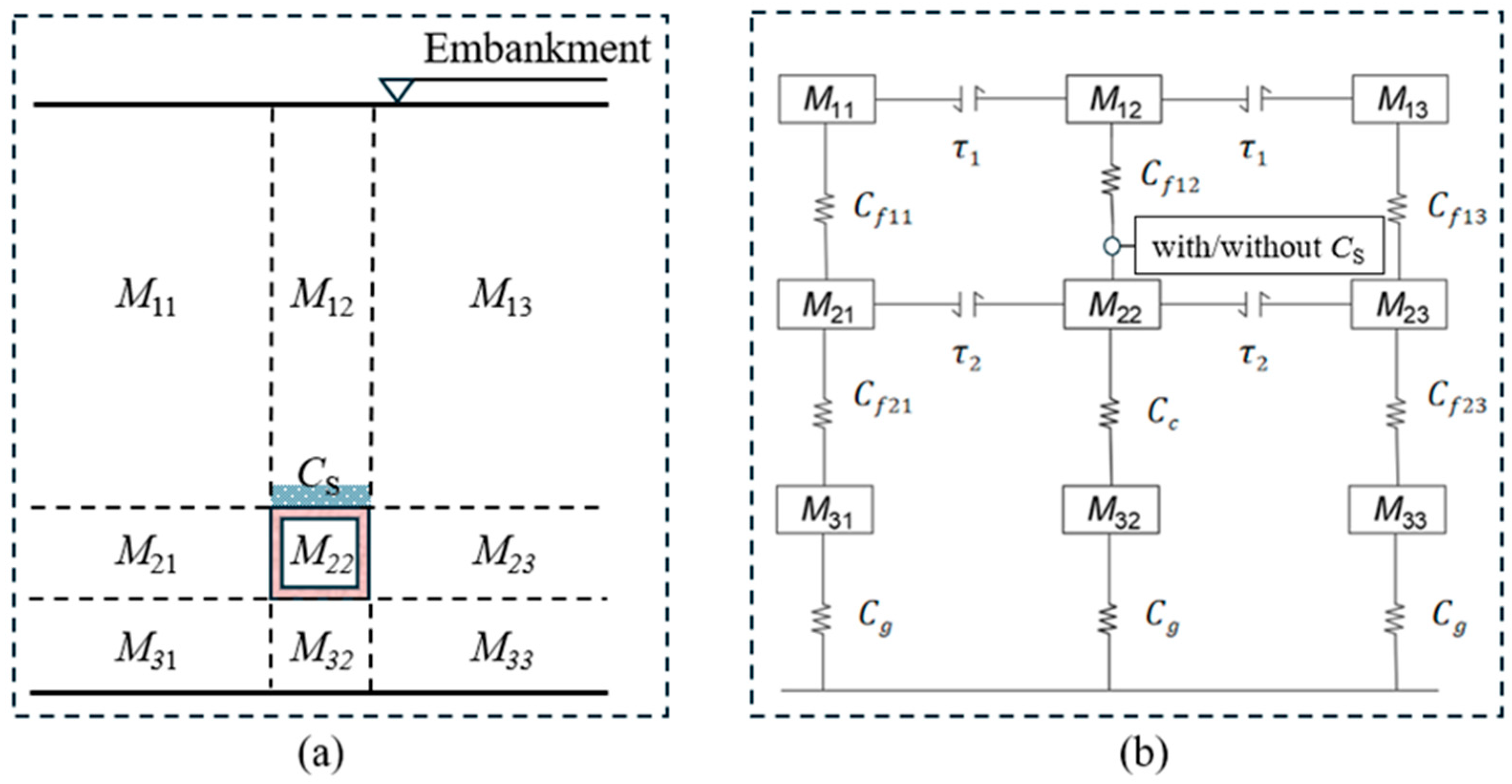
2.2.1. Stress Model of the Box Culvert with EPS Board

The equivalent stiffness of the central soil mass and the EPS board is less than that of the surrounding soil masses on the culvert roof. Consequently, a portion load of the central soil mass above the culvert is transferred to the surrounding soil masses through interface friction, resulting an increase in the VEP of surrounding soil masses at the culvert roof plane.
The high-fill culvert generally has an equal settlement plane within the fill due to the large height of the backfill, where the interaction between the central and surrounding soil masses disappears [2]. The stress model of the box culvert–soil system is depicted in Figure 2. The culvert is considered as an inverted elastic foundation beam. The culvert roof fill is represented by a linearly elastic half-space continuum with uniform material properties. Both the culvert and the foundation soil are assumed as rigid bodies.

2.2.2. The Vertical Earth Pressure on the Culvert Roof

The differential VEP between the culvert roof slab and both sides of the culvert roof at the same plane is defined by the following expression:
σ v t = σ s t σ c t
where σ c t represents the VEP on the culvert top slab and σ s t denotes the VEP on both sides at the same level.
Based on the settlement calculation method in elastic mechanics for rigid strip foundations [24], the differential settlement at the culvert roof plane is derived as follows:
δ t = σ v t ω c D 1 μ 2 E
where δ t represents the time-dependent differential settlement of the culvert roof plane; ω c is the coefficient associated with the length-to-width ratio of the rigid culvert [8]; and D means the width of the culvert. μ is Poisson’s ratio of the fill and E stands for the average elastic modulus of the fill above the culvert roof.
Assuming an influence radius r for the friction of the inner soil mass on both sides of the adjacent soil masses, the equilibrium equation for VEP on the culvert roof is expressed as follows:
γ H D + 2 r = D σ c t + 2 r σ s t
where γ denotes the gravity density of backfill above the culvert and H represents the backfill height over the culvert.
The deformation of backfill over culvert is determined using the formula for half-space elastomer subsidence under strip load [20]. The settlement (deformation) calculation formula is as follows:
w x = 1 π E F k i + C F k i = 2 x D ln 2 x / D + 1 2 x / D 1 ln 4 x 2 D 2 1 C = 2 ln r D + 1 + ln 2  
where w x represents the distribution function of settlement at the edge of the strip load, and x denotes the distance from the settlement calculation point to the center of the strip load.
Theoretically, the value of r is infinite. However, for an ideal elastomer, the ratio of the settlement at the edge beyond a range of 2D from the strip load’s edge to the settlement at the center of the strip load is less than 10%. Considering the backfill soil is not an ideal elastic material, the influence range of r can be taken as 2D in this analysis.
The constitutive model of the backfill and the EPS board adhere to the Burgers model [25,26,27,28]. The creep model consists of a Maxwell element and a Kelvin element in series; the Burgers model is depicted in Figure 3.
Consequently, the creep constitutive model of the backfill and the EPS board can be expressed as follows:
ε 1 t = 1 E m 1 + t η m 1 + 1 E k 1 1 e E k 1 t η k 1
ε 2 t = 1 E m 2 + t η m 2 + 1 E k 2 1 e E k 2 t η k 2
where E m 1 is the elastic modulus of the fill on both sides of the culvert within the height range of the culvert sidewall; E m 2 is the elastic modulus of the EPS board; η m 1 and η m 2 are the viscosity coefficient of the Maxwell model; E k 1 and E k 2 are the elastic modulus of the Kelvin elastic element; and η k 1 and η k 2 are the viscosity coefficient of the Kelvin viscous element.
The compressive deformations of the fill on both sides of the culvert within the height range of the culvert sidewalls are expressed as follows:
δ 1 t = h + h p σ s t + γ a h + h p 2 τ 2 ε 1 ( t )
where h is the culvert height, h p is the thickness of the EPS board, and γ a is the average gravity density of the fill adjacent to the culvert sidewall.
The long-term deformation of the EPS board is given by the following expression:
δ 2 t = h p σ c t ε 2 ( t )
The differential settlement δ t between the central and surrounding soil masses can be expressed as the differential deformation of compression between the EPS board and the soil on both sides of the culvert sidewall.
δ t = δ 2 t δ 1 t
By combining Equations (7)–(9), the following differential settlement δ t between the central and surrounding soil masses can be obtained:
δ t = h p σ c t ε 2 t h + h p σ s t + γ a ( h + h p ) 2 τ 2 ε 1 t
Beneath the culvert roof, the thickness of the flexible load-shedding material is negligible. Therefore, friction between the load-shedding material and the soil is disregarded, along with the weight of the load-shedding material.
The VEP on the culvert roof is affected by skin friction of the lateral soil mass acting on the culvert sidewall. In order to simplify the calculation expression, the average skin friction is considered here. Neglecting the friction between the EPS board and fill, as well as the self-weight of the EPS board, the average skin friction τ 2 on the culvert sidewalls is given as follows:
τ 2 = K h σ s t + γ a h p + γ a h 2   f + c
where K h represents the static earth pressure coefficient, which is computed as K h = μ / ( 1 μ ) ; c stands for the cohesion between the fill and culvert sidewall; and f = t a n   δ , where δ is the skin friction angle between the culvert sidewall and adjacent fill.
By combining Equations (2), (10) and (11), one can derive the VEP acting on the culvert roof plane.
σ c t = γ H 4 γ H h p E ε 2 t I h + h p E ε 1 t 5 R + 4 h p E ε 2 t + h + h p 1 K h E ε 1 t
σ s t = γ H + γ H h p E ε 2 t I h + h p E ε 1 t 5 R + 4 h p E ε 2 t + h + h p 1 K h E ε 1 t
with
I = γ H 1 K h + γ a h + h p / 2 K h γ a f h p K h γ a f h / 2 + c
R = ω c D 1 μ 2
The VEP coefficients on the top slab and on both sides of the top slab are expressed as follows:
K c t = σ c t γ H
K s t = σ s t γ H
The equivalent stiffness of the central soil mass and the EPS board is less than that of the surrounding soil masses on the culvert roof. Consequently, a portion load of the central soil mass above the culvert is transferred to the surrounding soil masses through interface friction, resulting in an increase in the VEP of surrounding soil masses at the culvert roof plane.

2.2.3. Horizontal Earth Pressure Along the Sidewall

The skin friction acting on the sidewall arises from the relative displacement between the sidewall and the sidewall fill. The HEP σ z t along the sidewall can be described as follows:
σ z t = K h σ s t + γ a h p + γ a z
The skin friction can be expressed as follows:
τ z t = K h σ s t + γ a h p + γ a z   f + c
where z represents the depth below the culvert roof slab plane.

2.2.4. Foundation Contact Pressure

The FCP is predominantly influenced by three components, i.e., the VEP on the culvert roof σ c t , the gravity force of the culvert G, and the friction forces on the culvert sidewalls F f .
The frictional force acting on the culvert side wall is given by the following expression:
F f = 0 h τ z t d z
By combining Equations (12) and (20), the average FCP can be determined.
P t = σ c t + G + 2 L 0 h τ z t d z D L
where L indicates the culvert length.

3. Numerical Modeling

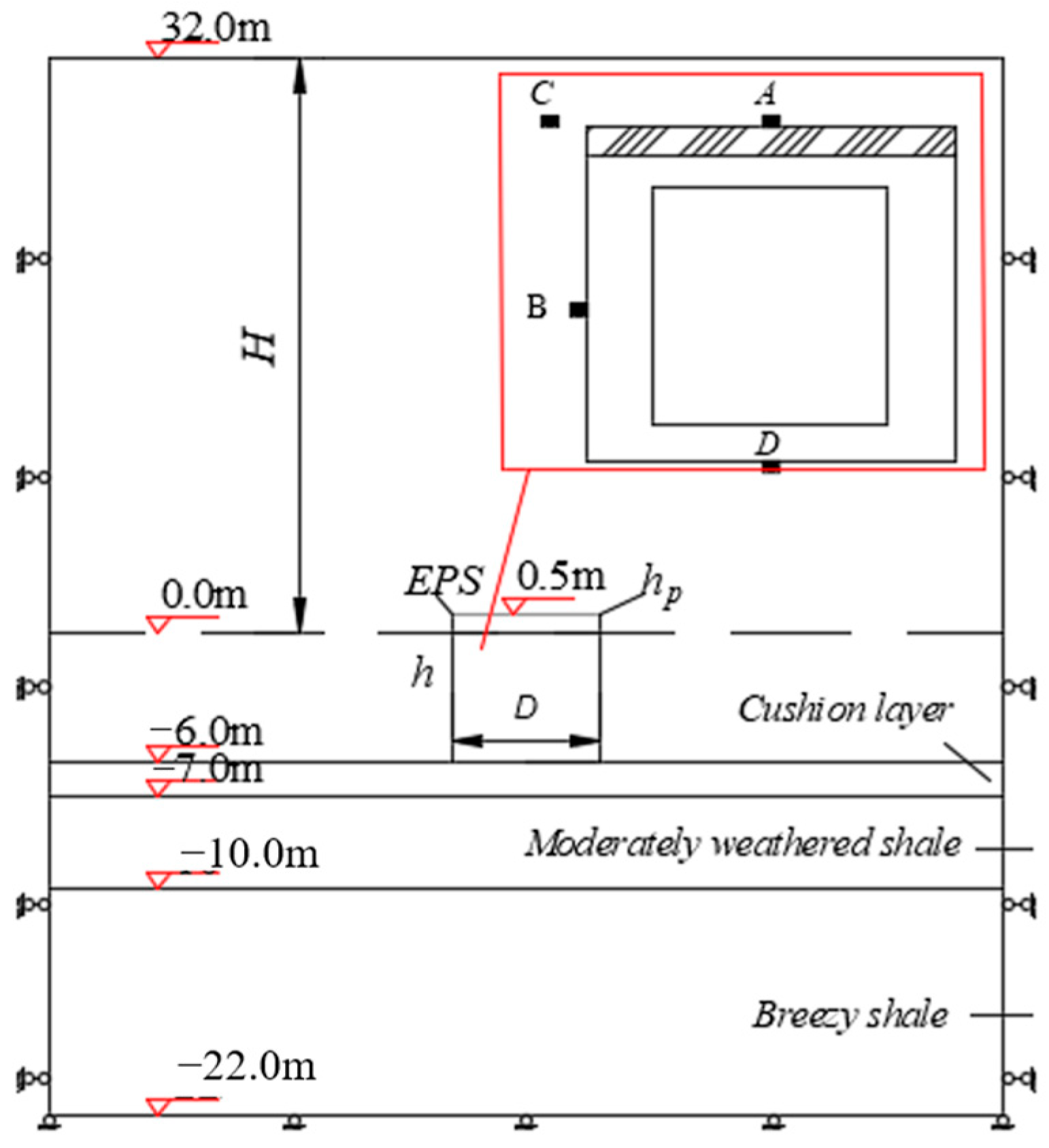
3.1. Establishment of the Numerical Model

The 3D numerical models for the rigid culvert under high fill with and without EPS board (i.e., embankment installation culvert, EC; induced trench installation culvert, ITC) are established by using FLAC-3D (v6.0) software. The numerical models and the earth pressure monitoring points A, B, C, and D are illustrated in Figure 4. The distance from point C to the edge of the culvert is 0.5 m, and points A, B, and C are all in the middle position.
The horizontal displacement is constrained around the model, while the bottom and the top of the model are set as fixed and free boundaries, respectively. The groundwater conditions are not considered in this analysis since the high-fill culvert is an installation work over weathered rock. The model dimensions are 60 m in width, 20 m in length, and 54 m in height. The culvert dimensions include a width of D = 7 m, a height of h = 6 m, and a length of L = 20 m. The thicknesses of the culvert roof slab, bottom slab, and side walls are 0.75 m, 1 m, and 1.5 m, respectively. A cushion layer of sand and graded gravel with a thickness of 1.0 m was laid on the weathered rock to level the surface. The foundation soil includes mid-weathered rock and slightly weathered rock with thicknesses of 3 m and 12 m. The backfill of sandy soil with a maximum filling height of H = 32 m was installed step by step with a thickness of 1.0 m for each layer. For the condition with the EPS board, a thickness of hp = 0.5 m of EPS board is placed exactly on the culvert roof.

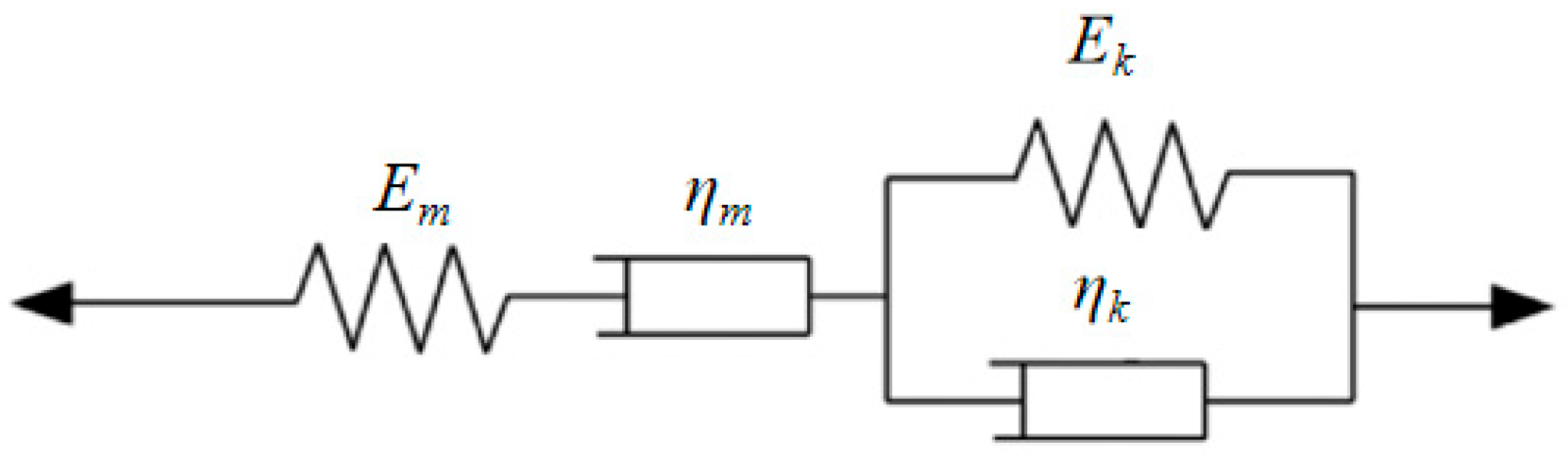
3.2. Material Parameters and Constitutive Model

In the numerical model, solid elements are employed for the EPS board, backfill, cushion, and foundation soils. While the culvert is represented by shell structural elements (Liner) to capture the interface behavior between the culvert and soil.
Different physical and mechanical properties of materials will lead to different results [29,30,31]. Material parameters specifying the properties of the materials are detailed in Table 1. Notably, the cushion and rock layers under the culvert are characterized as elastoplastic materials utilizing the Mohr–Coulomb model. The culvert is treated as a linear elastic material. The friction coefficient of EPS–soil is taken as 0.73 [32]. The creep behaviors of the sandy soil and EPS board are modeled by the Burgers model. As indicated in Shi et al. [33] and Gao et al. [19], the Burgers model is employed to represent the creep behavior of both backfill and the EPS board, and the associated creep parameters can be fitted from test data [34,35]. Considering the negligible deformation of the rock foundation, the creep of foundation soil is also ignored. The specific creep parameters are detailed in Table 2.

4. Long-Term Stress Characteristics of Box Culverts

4.1. Vertical Earth Pressure on the Culvert Roof Plane

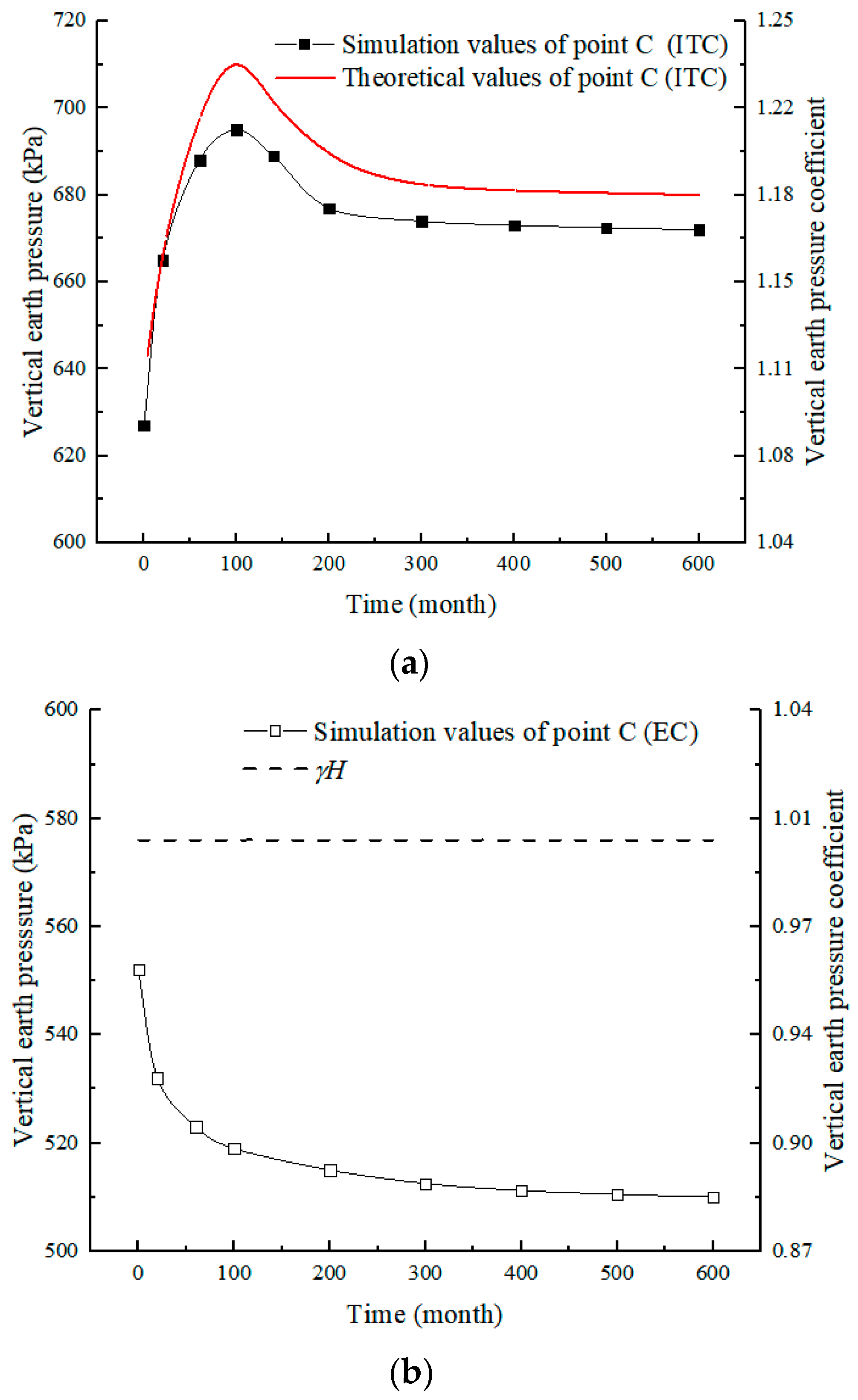
4.1.1. The Variation of VEP at the Midspan of the Top Slab with Time

The variation of VEP and the VEP coefficient with time are illustrated in Figure 5. The results demonstrate that the theoretical results are consistent with the numerical simulation results; the maximum difference is approximately 12%.
With EPS board, the VEP and VEP coefficient on the culvert roof slab initially decrease rapidly, then gradually increase with time, and reach an asymptotic value. Specifically, the earth pressure on the midspan of the top slab decreases from 305.2 kPa to 170.3 kPa in approximately 100 months, which is a 44% reduction compared to the initial post-construction pressure. Subsequently, it increases to 197.4 kPa around the 200th month. After 600 months, it gradually increases to 203.6 kPa, representing a 33% reduction from the completion of filling. The VEP coefficient ultimately decreases from 0.54 to 0.35.
For the without-EPS board condition, the VEP on the culvert roof slab initially increases rapidly, then gradually reaches a stable value. After 600 months, it gradually increases to 648.1 kPa, which is a 10% increase compared to the initial post-construction pressure. Simultaneously, the VEP coefficient at the midspan of the culvert roof increases from 1.02 to 1.13.
The study results reveal that the EPS boards significantly impact the VEP on the culvert roof. Compared to the condition without EPS board, the VEP on the culvert roof reduced by 46% after filling and eventually reduced by 65%.
Without EPS board, the culvert stiffness is significantly larger than those of the fill masses adjacent to the culvert. This discrepancy results in greater compression of the adjacent fills in comparison to the culvert. Differential settlement between the inner and the outside soil masses leads to the transfer of the VEP from the outside soil mass to the inner soil mass through the skin friction, which contributes to an increase in the VEP on the culvert roof. However, if the EPS board has adjusted the soil stiffness over the culvert, it is possible to alter the differential settlement between the central and surrounding soil masses over the culvert, which reverses the direction of the friction between the central and surrounding soil masses. Consequently, a portion of the earth pressure on the culvert roof is transferred to the surrounding soil masses through the friction.

4.1.2. The VEP on the Exterior of the Culvert Roof

Figure 6 illustrates the variation of VEP and the coefficient for the backfill outside the culvert roof. It is shown that the variation of the theoretical result is consistent with that of the numerical simulation; the maximum difference is about 15%.
With EPS conditions, the VEP and coefficient outside the culvert roof rapidly increase at the beginning of post-construction, then gradually decrease and reach a stable value. Specifically, the VEP outside the culvert roof rises from 627.5 kPa to 690.1 kPa in 100 months after backfilling, which is an increase of 10% compared to the completion of filling. The VEP coefficient increases from 1.08 to 1.17 during the post-construction. Conversely, for without-EPS conditions, the VEP and coefficient outside the culvert roof decrease nonlinearly and reach asymptotic values. Specifically, the VEP outside the culvert roof decreases from 552.3 kPa at the end of backfilling to 519 kPa after 100 months; the decrement is about 6%, then gradually decreases to 510 kPa after 600 months. Correspondingly, the VEP coefficient outside the culvert roof decreases from 0.96 to 0.88.
It is affirmed that the VEP at the culvert roof, mitigated by load reduction measures with EPS boards, is transferred to the culvert side. In comparison to the condition without EPS, the VEP at the culvert side increases by 14% after the backfilling and increases by 32% of 600 months after construction.

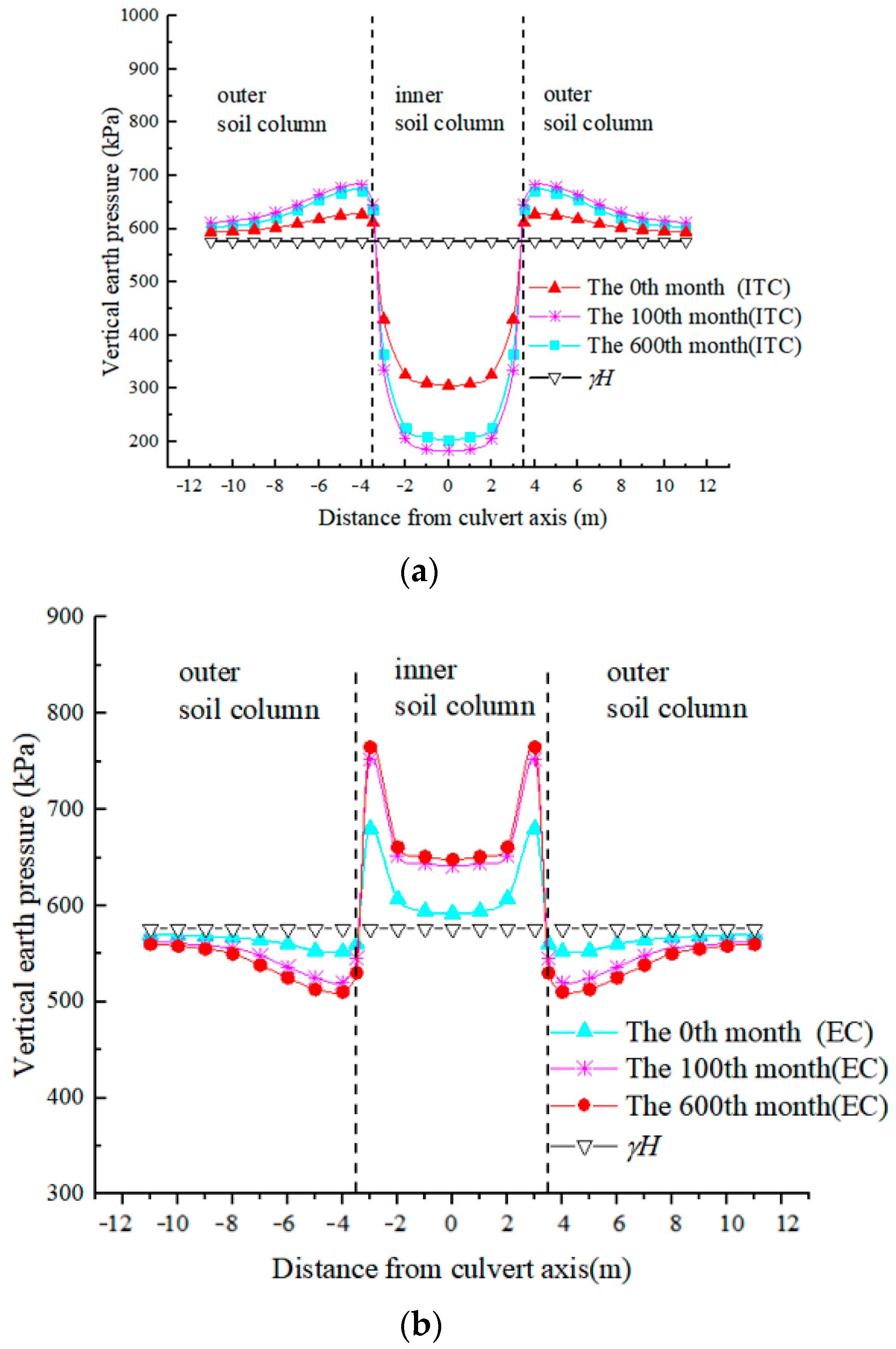
4.1.3. Distribution of VEP on the Culvert Roof Plane

Figure 7 illustrates the distribution of VEP on the culvert roof plane. For the condition with EPS, the VEP acting on the culvert roof slab is less than the backfill overburden pressure; it nonlinearly decreases with time. While the VEP on both sides at the culvert roof plane is larger than the backfill overburden pressure, it increases nonlinearly with time due to the compressible EPS board on the culvert roof, resulting in differential settlement between the central and surrounding soil mass; consequently, partial earth pressure on the culvert roof slab is transferred to the surrounding soil mass.
However, for the condition without EPS, the VEP on the culvert roof slab is larger than the backfill overburden pressure; it increases nonlinearly with time. While the VEP on both sides at the culvert roof plane is less than the backfill overburden pressure, it decreases nonlinearly with time because the culvert stiffness is larger than the adjacent soil. The distributions of VEP without EPS are the reverse of those with EPS.

4.2. Horizontal Earth Pressure on the Culvert Sidewall

4.2.1. Variation of HEP at the Midpoint of the Sidewall with Time

Figure 8 illustrates the variation of HEP at the midpoint of the sidewall with time. The results reveal consistent patterns between the theoretical method and numerical simulation, with a maximum error of 10%. For the condition with EPS, the HEP on the culvert sidewall rapidly increases from 233.2 kPa to 283.4 kPa in the first 100 months of post-construction, representing a 21.5% increment compared to the initial value of post-construction. Subsequently, it gradually decreases to 276.1 kPa after 600 months, approximately 18.4% higher than the initial value. For the condition without EPS, the HEP on the culvert sidewall nonlinearly decreases with time and tends towards an asymptotic value, which is significantly different from that of the condition with EPS. In comparison to without EPS, the HEP on the culvert sidewall increases by approximately 37.3% after 600 months.

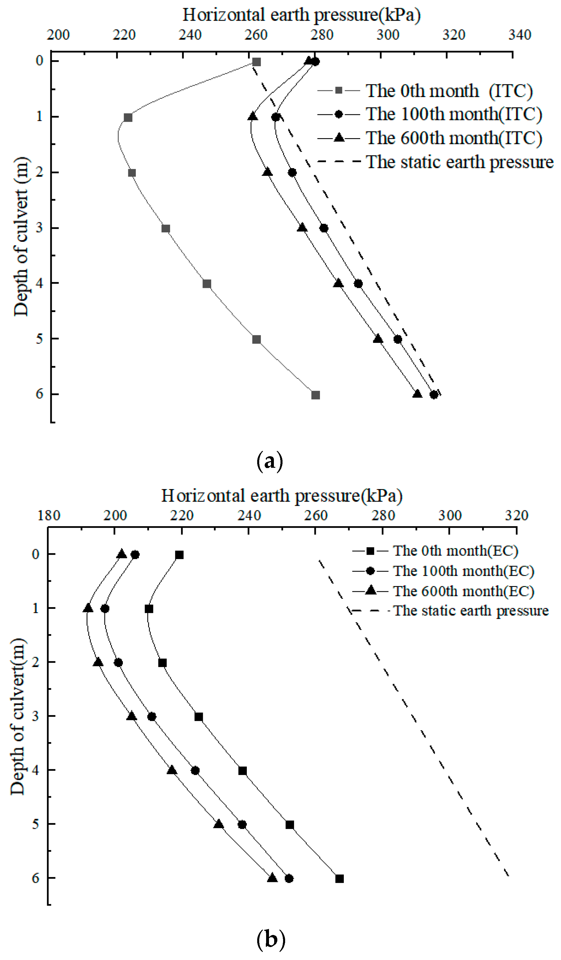
4.2.2. Distribution of HEP Along the Culvert Sidewall

Figure 9 displays the nonlinear distribution of HEP along the culvert sidewall for the conditions with and without the EPS board. This nonlinearity arises due to the substantial increase in lateral stiffness at the top and bottom slabs, in contrast to the comparatively lower stiffness in the middle of the sidewall. The action of HEP induces a bending deformation at the middle of the sidewall, resulting in a decrease in HEP.
For the with-EPS condition, the HEP along the sidewall increases nonlinearly with time and then gradually approaches a stable value. Overall, the HEP along the culvert sidewall is lower than the static earth pressure, despite the additional earth pressure over the culvert roof slab transferred to the surrounding soil mass increasing the HEP; the bending deformation of the sidewall counteracts this load. Conversely, for the without-EPS condition, the HEP along the sidewall decreases with time. Comparative analysis demonstrates that, although EPS boards effectively reduce the VEP on the top slab, they concurrently enhance the HEP on the sidewall.

4.3. Foundation Contact Pressure on the Culvert Bottom

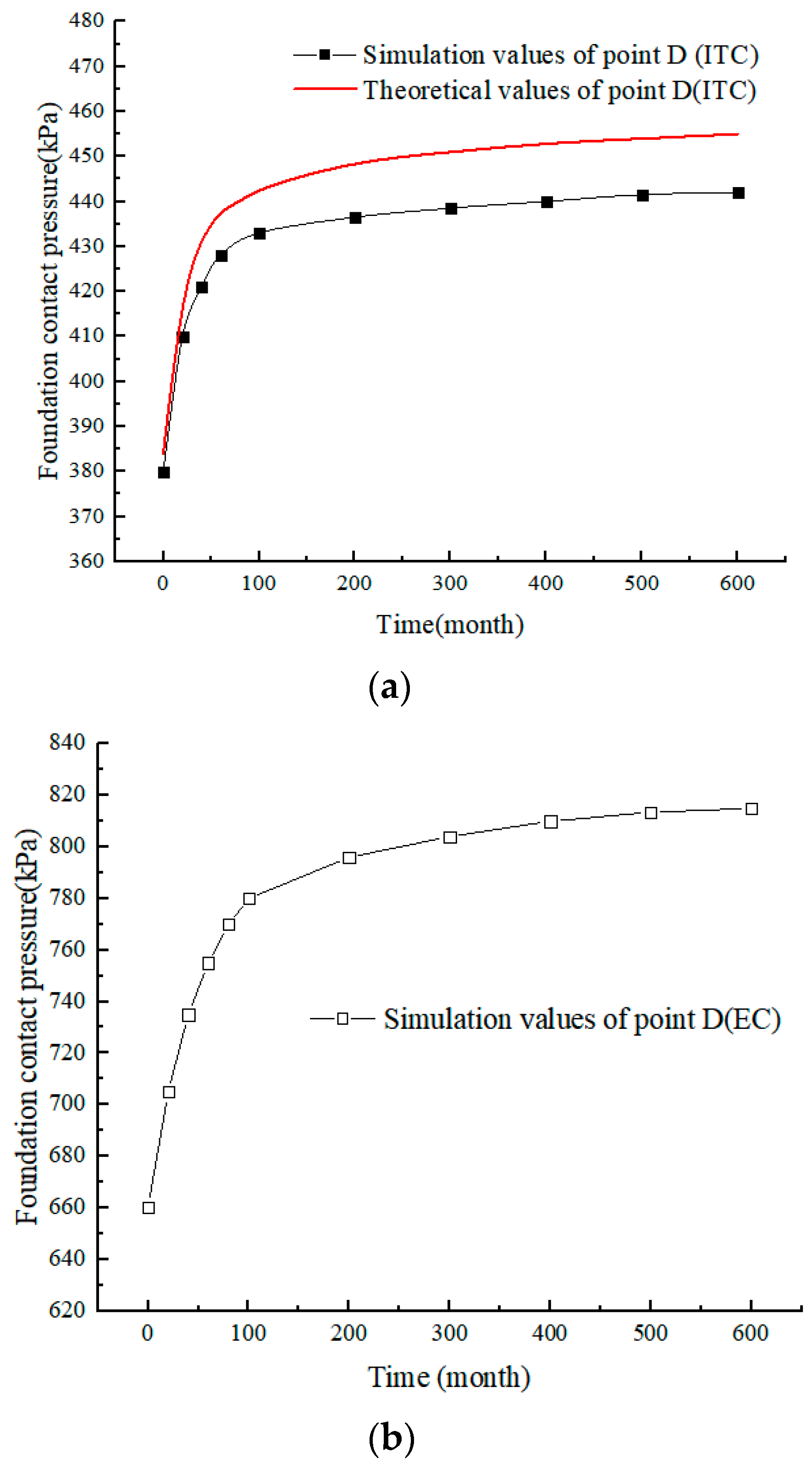
4.3.1. Variation of FCP at Midpoint of Bottom Slab with Time

The variations of FCP at the midpoint of the culvert bottom slab with time are illustrated in Figure 10. It is shown that the theoretical method result is consistent with that of the numerical simulation, with a maximum error of 5%.
For the with-EPS condition, the pressure at the midpoint of the bottom slab nonlinearly increases with time and approaches an asymptotic value eventually. Specifically, the midpoint pressure increases by 15.8% compared to the initial post-construction. This variation is similar to that of the without-EPS condition, characterized by an initial rapid increase, then gradually approaching a stable value. For the without-EPS condition, the FCP at the midpoint of the bottom slab increases by 24.2% compared to the initial post-construction. Comparison results reveal that the FCP for the with-EPS condition is less than that for the without-EPS condition; the decrements are approximately 42.4% at the end of construction and 46.0% after 600 months.

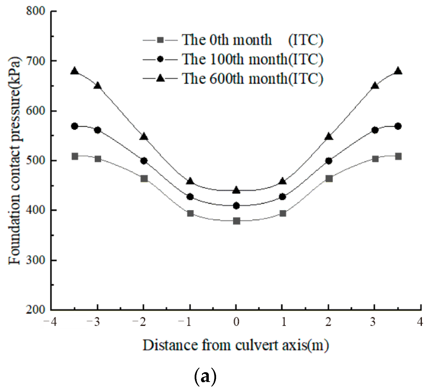
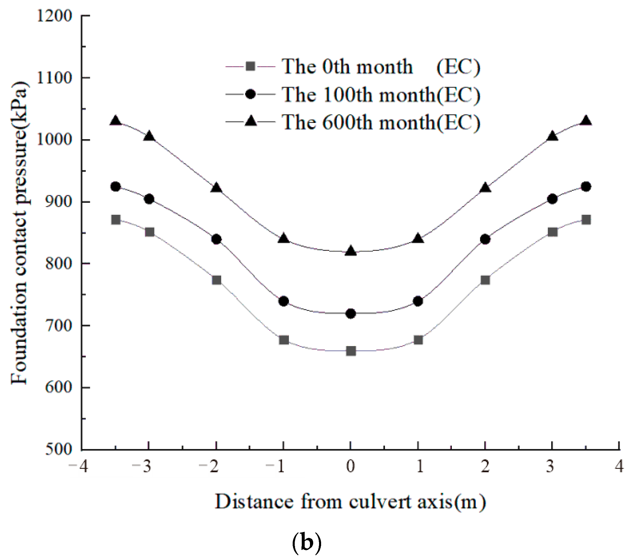
4.3.2. Distribution of Foundation Contact Pressure

The FCP consists of three parts, i.e., the VEP at the culvert roof, the self-gravity of the culvert, and the friction forces along the culvert sidewalls. The distributions of FCP are shown in Figure 11. The results reveal that the FCP exhibits an approximately U-shaped distribution along the bottom slab; it increases nonlinearly with time for both conditions, with and without the EPS board.

4.4. Discussion

The relevant literature [18,36] adopting the EPS load reduction technology was summarized and analyzed, and the coefficients of earth pressure acting on the culvert roof after the completion of filling were extracted. The earth pressure coefficients with EPS board load reduction in this paper were compared to those that explore the load reduction effect of EPS boards. After setting the EPS board on box culverts, the vertical earth pressure coefficients acting on the culvert roof are less than 1.0, which are 0.30 and 0.33, with the filling heights of 24 m and 32 m, respectively [18,36]. The final earth pressure coefficient acting on the culvert roof in this analysis is 0.34 with a filling height of 32 m. The rationality of the theoretical calculation and numerical model in this paper has been further verified.
Furthermore, through comparative analysis, it is found that although the vertical earth pressure acting on the culvert roof was reduced by setting the soft layer on the culvert roof, partial earth pressure on the culvert top slab is transferred to the surrounding soil mass through friction, resulting in an increase in the horizontal earth pressure acting on the culvert sidewall. This was consistent with the research results of this article.

5. Conclusions and Recommendations

The coupling creep of the EPS board and soil induces the variation of the culvert–soil stress states over time under high fill. This paper has established a mechanical model for the work performance of the “backfill–culvert” system with or without an EPS board. The formulas for calculating the earth pressures around the culvert have been proposed. The long-term stress characteristics of the box culvert with EPS board are obtained, and the accuracy of the theoretical approaches is validated by numerical simulations. Main findings and conclusions are summarized as follows:
(1)
The earth pressure acting on the top slab of the box culvert first decreases rapidly, then increases gradually with time; the stable value decreases by 33% compared to the end of the construction period. Concurrently, the VEP at the outer side of the culvert roof first increases rapidly, then decreases and gradually approaches an asymptotic value, which increases by 7% compared to that of the initial stage of post-construction.
(2)
The HEP on the sidewall of the box culvert first nonlinearly increases and then gradually decreases with time. The final value increases by 18.4% compared to that of the end of construction.
(3)
The FCP of the box culvert increases nonlinearly with time and approaches a stable value, which increases by 15.8% compared to that of the initial stage of the post-construction.
(4)
Although the EPS board reduces the earth pressure on the culvert roof, the frictional force on the culvert sidewall still leads to an increase in the FCP. Furthermore, the HEP and FCP of the box culvert show increments of about 37.3% and 46.0%, respectively, compared to the condition without the EPS board. The creep effect of EPS board and fill should be considered to avoid structural diseases in the design of box culverts with EPS board.
(5)
This analysis is only the preliminary theoretical basis for the long-term stress characteristics of high-fill culverts under load reduction conditions. Due to the lack of long-term field monitoring data, the theoretical results of this analysis were validated using numerical results. For future research, long-term field monitoring should be carried out to further verify the theoretical results, for example, by integrating field monitoring of actual culvert systems to verify that the predicted stress evolution matches reality.

Author Contributions

Conceptualization, Z.J. and B.C.; methodology, Z.J.; investigation, Z.J. and B.C.; resources, B.C.; data curation, Z.J.; writing—original draft, Z.J., B.C. and G.R.; writing—review and editing, Z.J., B.C., G.R., R.L. and L.D.; visualization, Z.J.; funding acquisition, B.C. All authors have read and agreed to the published version of the manuscript.

Funding

This work was supported by the National Natural Science Foundation of China (Grant No. 52178370).

Data Availability Statement

The original contributions presented in this study are included in the article. Further inquiries can be directed to the corresponding author.

Acknowledgments

The authors would like to express gratitude to the China University of Geosciences (Wuhan) for their valuable support during this study. The authors have reviewed and edited the output and take full responsibility for the content of this publication.

Conflicts of Interest

Author Ruiping Luo was employed by Hubei Provincial Academy of Building Research and Design Co., Ltd. The remaining authors declare that the research was conducted in the absence of any commercial or financial relationships that could be construed as a potential conflict of interest.

References

  1. Chen, B.G.; Sun, L. Performance of a reinforced concrete box culvert installed in trapezoidal trenches. J. Bridge Eng. 2014, 19, 120–130. [Google Scholar] [CrossRef]
  2. Marston, A. The theory of external loads on closed conduits in the light of the latest experiments. Highw. Res. Board Proc. 1930, 9, 138–170. [Google Scholar]
  3. Brown, C.B. Forces on rigid culverts under high fills. J. Struct. Div. ASCE 1967, 93, 195–215. [Google Scholar] [CrossRef]
  4. Spangler, M.G. A theory of loads on negative projecting conduits. Highw. Res. Board Proc. 1950, 30, 153–161. [Google Scholar]
  5. Vaslestad, J. Load reduction on buried rigid pipes. In Proceedings of the Pipeline Crossings, Specialty Conference, Denver, CO, USA, 25—27 March 1991. [Google Scholar]
  6. McGuigan, B.L.; Valsangkar, A.J. Centrifuge testing and numerical analysis of box culverts installed in induced trenches. Can. Geotech. J. 2010, 47, 147–163. [Google Scholar] [CrossRef]
  7. Ahmed, M.R. Experimental Investigations into the Role of Geosynthetic Inclusions on the Earth Pressure Acting on Buried Structures. Ph.D. Thesis, McGill University, Montreal, QC, Canada, 2016. [Google Scholar]
  8. Meguid, M.A.; Youssef, T.A. Experimental investigation of the earth pressure distribution on buried pipes backfilled with tire-derived aggregate. Transp. Geotech. 2018, 14, 117–125. [Google Scholar] [CrossRef]
  9. Zhang, C.G.; Wu, K.; Kang, L.H.; Li, H.X. VEP against an induced trench installation culvert in unsaturated soils. J. Harbin Inst. Technol. 2023, 55, 80–87. (In Chinese) [Google Scholar]
  10. Qin, X.; Ni, P.; Zhou, M. Improved analytical solution of vertical pressure on top of induced trench rigid culverts. Geosynth. Int. 2017, 24, 615–624. [Google Scholar] [CrossRef]
  11. Beju, Y.Z.; Mandal, J.N. Compression creep test on expanded polystyrene (EPS) geofoam. Int. J. Geotech. Eng. 2016, 10, 401–408. [Google Scholar] [CrossRef]
  12. Sun, L.; Hopkins, T.C.; Beckham, T.L. Long-term monitoring of culvert load reduction using an imperfect ditch backfilled with geofoam. Transp. Res. Rec. 2018, 2212, 56–64. [Google Scholar] [CrossRef]
  13. Gnip, I.Y.; Vaitkus, S.; Keršulis, V.; Vėjelis, S. Long-term prediction of compressive creep development in expanded polystyrene. Polym. Test. 2008, 27, 378–391. [Google Scholar] [CrossRef]
  14. Gnip, I.Y.; Vaitkus, S.; Keršulis, V.; Vėjelis, S. Analytical description of the creep of expanded polystyrene (EPS) under long-term compressive loading. Polym. Test. 2011, 30, 493–500. [Google Scholar] [CrossRef]
  15. Vaslestad, J.; Johansen, T.H.; Holm, W. Load reduction on rigid culverts beneath high fills: Long-term behavior. In Transportation Research Record; National Academy Press: Washington, DC, USA, 1993; pp. 58–68. [Google Scholar]
  16. Hou, H.B.; Li, S.; You, Z.G.; He, Y.Z. Analysis of consolidation creep of backfill soil for unloaded high-filled cut-and-cover tunnel based on the, P.F.C.2.D. Sci. Technol. Eng. 2022, 22, 14360–14369. (In Chinese) [Google Scholar]
  17. Li, S.; Jianie, Y.C.; Ho, I.H.; Ma, L.; Yu, B.; Wang, C. Evolution of load reduction for high-filled cut-and-cover tunnels subjected to soil creep. Int. J. Geomech. 2021, 21, 04021172-1. [Google Scholar] [CrossRef]
  18. Chen, B.G.; Song, D.B.; Wang, C.; He, Y.H. Long-term behavior of load reduction culvert under high fills. J. Hydraul. Eng. 2015, 46, 117–123. (In Chinese) [Google Scholar]
  19. Gao, Q.; Chen, B.G.; Wu, S.; Yuan, S.; Sun, M.Y. Long-term stress characteristics and load reduction effect of high-fill box culverts with EPS slabs. Rock Soil Mech. 2023, 44, 2151–2160. (In Chinese) [Google Scholar]
  20. Birgul, R.; Al-shammari, F.M.W.; Yaman, I.O.; Aktan, M.H. Acoustic emission evaluation of concrete culverts. Res. Nondestruct. Eval. 2005, 15, 191–208. [Google Scholar] [CrossRef]
  21. Melchiorre, J.; D’Amato, L.; Agostini, F.; Rizzo, A.M. Acoustic emission onset time detection for structural monitoring with u-net neural network architecture. Dev. Built Environ. 2024, 18, 100449. [Google Scholar] [CrossRef]
  22. Gong, Y.; Lin, S.; He, F.; He, Y.; Song, J. Damage identification of prefabricated reinforced concrete box culvert based on improved fuzzy clustering algorithm and acoustic emission parameters. Adv. Mater. Sci. Eng. 2021, 2021, 6660915. [Google Scholar] [CrossRef]
  23. Melchiorre, J.; Bertetto, A.M.; Rosso, M.M.; Marano, G.C. Acoustic emission and artificial intelligence procedure for crack source localization. Sensors 2023, 23, 693. [Google Scholar] [CrossRef]
  24. Xu, Z.L. A Concise Course in Elasticity; Higher Education Press: Beijing, China, 2018. [Google Scholar]
  25. Wang, F.; Miao, L.C.; Zhang, Y.J. A simplified method to predict creep behavior of the Yangtze River sand. Bull. Eng. Geol. Environ. 2012, 71, 317–324. [Google Scholar] [CrossRef]
  26. Wang, Y.H.; Lau, Y.M.; Gao, Y. Examining the mechanisms of sand creep using DEM simulations. Granul. Matter 2014, 16, 733–750. [Google Scholar] [CrossRef]
  27. Taylor, S.B.; Manbeck, H.B.; Janowiak, J.J. Modeling structural insulated panel (SIP) flexural creep deflection. J. Struct. Eng. 1997, 123, 1555–1697. [Google Scholar] [CrossRef]
  28. Yong, Z.; Chin, J.L.; Henry, W. Time dependent viscoelastic behaviour of EPS geofoam. Appl. Mech. Mater. 2013, 330, 1095–1099. [Google Scholar]
  29. Wu, Y.; Li, N.; Wang, X.; Cui, J.; Chen, Y.; Wu, Y.; Yamamoto, H. Experimental investigation on mechanical behavior and particle crushing of calcareous sand retrieved from South China Sea. Eng. Geol. 2021, 280, 105932. [Google Scholar] [CrossRef]
  30. Wu, Y.; Yamamoto, H.; Cui, J.; Cheng, H. Influence of Load Mode on Particle Crushing Characteristics of Silica Sand at High Stresses. Int. J. Geomech. 2020, 20, 04019194. [Google Scholar] [CrossRef]
  31. Wu, Y.; Cui, J.; Huang, J.; Zhang, W.; Yoshimoto, N.; Wen, L. Correlation of critical state strength properties with particle shape and surface fractal dimension of clinker ash. Int. J. Geomech. 2021, 21, 04021071. [Google Scholar] [CrossRef]
  32. Chrysikos, D.; Atmatzidis, D.; Missirlis, E. EPS geofoam surface shear resistance. In Proceedings of the 8th IGS (International Geotechnical Symposium on Disaster Mitigation), Yokohama, Japan, 26–28 May 2006; Millpress: Rotterdam, The Netherlands, 2006; pp. 1647–1650. [Google Scholar]
  33. Shi, X.Q.; Xue, Y.Q.; Wu, J.C.; Zhang, Y.; Ye, S.; Yu, J. Uniaxial compression tests for creep model of saturated sand in Changzhou. J. Eng. Geol. 2007, 15, 212–216. (In Chinese) [Google Scholar]
  34. Cai, G.J.; Chen, S.H.; Zhao, D.; Zhou, Y. Experimental study on creep characteristics of saturated sand and its influencing factors. J. Eng. Geol. 2019, 27, 1048–1055. [Google Scholar]
  35. Kang, Y.; Li, X.; Tan, J. Uniaxial tension and tensile creep behaviors of EPS. J. Cent. South Univ. Technol. 2010, 15, 202–205. [Google Scholar] [CrossRef]
  36. Zhang, Y.Q.; Chen, B.G.; Meng, Q.D.; Xu, X. Stress mechanism and foundation contact pressure of high fill culvert under load reduction condition. Rock Soil Mech. 2019, 40, 4813–4818+4847. [Google Scholar]
Figure 1. Soil–box culvert interaction model: (a) schematic diagram of high-fill box culvert and (b) with/without EPS board.
Buildings 15 01954 g001
Figure 2. Schematic of the theoretical model for long-term effects.
Buildings 15 01954 g002
Figure 3. The typical schematic of Burgers model.
Buildings 15 01954 g003
Figure 4. Layout of the numerical model and the monitoring points.
Buildings 15 01954 g004
Figure 5. The variation of VEP on the top slab with time: (a) with EPS board and (b) without EPS board.
Buildings 15 01954 g005
Figure 6. Variation of VEP outside the culvert roof with time: (a) with EPS board and (b) without EPS board.
Buildings 15 01954 g006
Figure 7. VEP on the culvert roof plane: (a) with EPS board and (b) without EPS board.
Buildings 15 01954 g007
Figure 8. Variation of HEP on the culvert sidewall with time: (a) with EPS board and (b) without EPS board.
Buildings 15 01954 g008
Figure 9. HEP along the culvert sidewall: (a) with EPS board and (b) without EPS board.
Buildings 15 01954 g009
Figure 10. Temporal evolution of the FCP: (a) with EPS board and (b) without EPS board.
Buildings 15 01954 g010
Figure 11. Distribution of FCP: (a) with EPS board and (b) without EPS board.
Buildings 15 01954 g011aBuildings 15 01954 g011b
Table 1. Material parameters.
MaterialElastic Modulus
/MPa
Density
/kg∙m−3
Poisson’s RatioPorosityFriction Angle
Cohesion
/kPa
Sandy soil3218000.2640%330
Culvert30,00025000.20---
EPS board3200.2094%--
Cushion layer30021500.25-345
Mid-weathered rock strata15,00026500.23-29600
Slight-weathered rock strata26,00027200.20-352000
Table 2. The Burgers model parameters.
MaterialEm/MPaEk/MPa η m /MPa∙h η k /MPa∙h
EPS board0.53.143.642 × 1046.727
Sandy soil3075.651.264 × 1043.315
Disclaimer/Publisher’s Note: The statements, opinions and data contained in all publications are solely those of the individual author(s) and contributor(s) and not of MDPI and/or the editor(s). MDPI and/or the editor(s) disclaim responsibility for any injury to people or property resulting from any ideas, methods, instructions or products referred to in the content.

