Article

NLFEA Behavior of Heat-Damaged Key Joints in Precast Concrete Segmental Bridge

by
Bara’a R. Alnemrawi
* and
Rajai Al-Rousan
Department of Civil Engineering, Engineering, Jordan University of Science and Technology, P.O. Box 3030, Irbid 22110, Jordan
*
Author to whom correspondence should be addressed.
Buildings 2025, 15(11), 1890; https://doi.org/10.3390/buildings15111890
Submission received: 16 April 2025 / Revised: 16 May 2025 / Accepted: 27 May 2025 / Published: 30 May 2025
(This article belongs to the Section Building Materials, and Repair & Renovation)

Abstract

The provided shear key joints are practically unreinforced due to their small size, and their performance directly affects the structural behavior of the segmental concrete bridge. In addition, these joints are usually dry and distributed over the contact region between the two connected bridge parts. The current research examines the effect of the lateral confinement pressure (1, 2, 3, 4, 5, and 6) MPa and the elevated temperature values (23, 200, 400, and 600) °C on the behavior of single dried shear key joints structural behavior tested under concentrated static loading using the Nonlinear Finite Element Analysis (NLFEA) procedure. The simulation models were first validated using experimental data from the literature and compared using the ultimate deflection, ultimate load, cracking propagation, and failure modes using ABAQUS software, where the available Concrete Damage Plasticity model was utilized. Twenty-four models were simulated using different combinations of the parameters included in the parametric study. Results were reported in terms of their load-deflection behavior, structural characteristics, cracking propagation within the shear key zone, and the final failure modes. It has been found that the initial stiffness, ultimate deflection, and ultimate strength values were all increased under increasing confinement pressure. Moreover, the situation is totally different when the exposure temperature exceeds 400 °C. Finally, a new formula was introduced for predicting the shear key capacity after being validated against numerical and experimental data sets, along with different design codes and standards. A very good agreement was reached for the new proposed mathematical equations.

1. Introduction

The construction of concrete bridges has widely increased in recent years as segments connected with shear keys distributed within the connected region’s length [1,2]. The different segments are also attached by applying the post-tensioned type’s prestressing force [3]. The construction of this type of bridge is found to be economical, safe, and fast while being environmentally sustainable [4,5]. However, the precast box girder type is usually used in this system and assembled together using prestressing forces, ensuring the fast construction process predicted from this bridge type [6]. The connection regions where the shear keys exist are considered loading discontinuous regions [7], where bending and shear forces are transmitted between the two parts. Therefore, the shear keys are provided to support the loading transfer mechanism. Many types of shear keys, such as epoxied or dried joints, could be installed. However, the low shear strength of the epoxied type and associated imperfections reduce their applicability, regardless of their durable characteristics. In addition, epoxy material takes much time to harden, limiting its utilization where fast construction is required. Besides, a brittle type of failure forms the final behavior of these joints, which is not favorable in the concrete design. Due to the mentioned disadvantages, the AASHTO standards for bridge construction prohibit using the epoxied joint type [8], and the utilization of the single dried shear key type is recommended.
Increasing the post-tensioning force increases the initiated lateral confinement pressure within the joint region, increasing the joint’s ultimate shear strength and stiffness. Moreover, the structural behavior of the shear key joints is highly dependent on the frictional forces between the attached areas. However, the shear flow mechanism across the contact regions of the dry shear keys could be easily addressed and carried out by the failure plane’s concrete compressive strength, bearing, and friction forces [9]. A major factor affecting the used joint’s structural behavior is its geometrical shape and numbers inserted at the connection length [10], where the transfer forces are increased by increasing the number of provided keys [11]. Concrete crushing and shearing-off are the major failure modes observed by the unreinforced single-shear key joints [12]. Li et al. [10] studied the transfer process under the effect of combined shear and bending stresses, where failure was associated with the opening of the connected parts and a new mathematical formula was introduced.
Exposing the structural system under investigation to an elevated temperature scenario resulted in affecting the microstructural components of their constitutive materials, such as concrete and steel. It was stated by Pulkit and Adhikary [13] that heat-induced evolution has a direct and significant influence on the material’s mechanical, thermal, and kinematic characteristics. In addition, the pore size of the affected concrete mixture was also affected along with the microcracking propagation process, especially within the hardened cement paste part. Moreover, the aggregates used within the mixture also experienced crystallization and disassociation of their components observed at temperature values higher than 400 °C. Chen et al. [14] investigated the behavior of steel material under elevated temperatures, including high-strength and mild types, using two examining methods (transient and steady-state). It was found that there was almost no difference between the mechanical properties (yield strength and elastic modulus) of the two types at temperatures less than 540 °C. The resulting observations were confirmed by other sources in the literature where further studies were carried out [15,16]. Finally, the bond behavior between the concrete and steel materials was a major area of investigation that is highly dependent on the exposure temperatures of the structural system [17].
The shear behavior of key joints has been investigated numerically and experimentally by different researchers in the literature under various concrete grades, frictional coefficients, shear key numbers, geometrical shapes, and confinement pressures. The effect of the prestressing tendons reinforcement arrangements in resisting the different types of structural loadings (axial, bending, shear, and torsion) was investigated by Algorafi et al. [18]. An analytical expression based on wide experimental and empirical observations was introduced by the AASHTO standards [8], where different parameters were included, such as the prestressing forces, the key geometry, and the concrete grade. Zhou et al. [6] evaluated the predictability of the AASHTO [8] equation and revealed that the shear capacities were underestimated due to the neglected cracking propagation process. A new empirical formula based on coupling the friction and shear forces was proposed by Rombach [1] using the numerical analysis procedure, and the predictions were observed to be dependent on the number of utilized shear keys. Different mathematical formulas [19,20,21] and code standards [8,22,23] proposed equations for predicting the shear strength capacity of the dried joints with different efficiencies, including different concrete compressive strengths [24].
The NLFEA method was carried out by different researchers in the literature. The ANSYS and ABAQUS software were used in the literature to analyze the structural behavior of simply supported post-tensioned segmental bridges [25,26,27,28]. Turmo et al. [19] avoid using a very fine mesh by the flat joint model to mitigate the high required computational time. Joints were simulated using interfacial elements with appropriate constitutive material and geometrical modeling using a macro modeling technique, but the stresses, strains, and cracking propagation could not be captured using this technique. Therefore, an NLFEA model that fulfills the requirements to capture the overall structural behavior and the associated cracking observations is required. A numerical model-based flat joint approach was carried out by Kim et al. [29], similar to the utilized one by Turmo et al. [19,30], where the nonlinear behavior of the simulated joints was defined using different testing results and constitutive material modeling. In addition, four types of shear key joints with different numbers up to seven were studied by Alcalde et al. [20], where the failure modes and cracking propagations process were detailed in terms of the average shear stress-induced. It has been stated that decreasing the number of used shear keys across the joint’s length increases the average shear stress value, and this confirmed what has been reported by Zhou et al. [6].
Concrete material’s physical, mechanical, and chemical characteristics are affected by being exposed to elevated temperatures [31,32]. The resulting degradation includes the strength and serviceability aspects, where the internal and external moisture are lost depending on the temperature level, and the internal chemical components are changed [33]. Besides, the steel reinforcement is also affected under temperature values of more than 500 °C, including its yield and ultimate strength [34]. Therefore, addressing the behavior of important structural members under a fire situation is essential due to their direct effect on the structural system brittleness and cracking propagation, besides the resulting degradation in their material properties. In addition, shear key joints are subjected to different confinement levels due to their location in the bridge system and their direct exposure to pressure effects at more than one location. Consequently, addressing the combined effect of high temperature and pressure confinement on the shear behavior of segmental key joints was not previously investigated in the literature.
This study investigated the shear behavior of key joints using the NLFEA method using ABAQUS software [35], where their performance was examined under the effect of different confinement levels and temperature values. The NLFEA models were tested until failure, including the contact behavior between the attached parts. The models were first validated using the experimental work by Zhou et al. [6], where the loading and cracking propagation behavior were compared. After that, a parametric study was carried out, including the effect of different temperatures (23, 200, 400, and 600) °C and confinement levels (1, 2, 3, 4, 5, and 6) Mpa. Finally, a new theoretical model was introduced to predict the shear capacity of the shear key joints. The prediction results were compared with experimental, analytical, and numerical results, where good accuracy was recorded.

2. Nonlinear Finite Element Analysis (NLFEA)

The NLFEA simulation was performed in this study using ABAQUS software [35], where the modeling of concrete material could be addressed using two main approaches: the Concrete Damage Plasticity Model (CDP) and the smeared crack approaches. The CDP model was used, and the associated defined parameters are as follows (0.1, 0.0005, 36, 1.16, and 0.667) for the eccentricity, viscosity, dilation, concrete stress ratio, and invariant ratio, as proposed by Kmiecik and Kamiński [36]. However, many assumptions were adopted in this study based on experimental observations introduced by Zhou et al. [6], such as the bond behavior between the interfacial components (loading and confining pressures plates with concrete blocks) and boundary conditions. The results of this study are only applicable to this type of bridge key joints (segmental) with similar confining and loading conditions. In addition, the materials and geometrical properties are illustrated in the following sections:

2.1. General Overview

The NLFEA modeling conducted in this research is obtained from Zhou et al. [6] and simulated using ABAQUS software [35], as shown in Figure 1. The model has a 500 mm width, 620 mm height, and 250 mm total depth. The joints were reinforced with two 12 mm diameter rebars at each section, as per Figure 1. Loading was applied at the top of the joints using a displacement-controlled procedure directly applied at the top of a steel plate positioned at the loading location to mitigate any stress concentration possibility. In addition, the joints were supported at their bottom, where movement and rotations were prohibited in all directions (fixation). Moreover, pressure was applied at the right and left sides of the middle height of the joints to provide the confinement effect, as per Zhou’s experimental working procedure [6].
The problem was simulated as a plane stress problem where the out-of-plane effect is ignored, and the computational complexity and required time are significantly reduced [37]. However, ignoring the out-of-plane stresses has no effect due to the small thickness of the key joints, as adopted and confirmed by previous research in the literature [38]. Loading was applied at the top of the simulated single dry shear key joints. Cracking was first developed within the shear plane. After a mesh convergence study, the simulated models were meshed with two mesh sizes: 2.5 mm for the stress-concentration regions at the interfacial zone between the two connected parts and 20 mm for the remaining regions. The adopted geometrical modeling of the key joint is illustrated in Figure 1, as per the experimental specimens of Zhou et al. [6]. In addition, the finite element modeling adopts finer meshes within the regions of stress concentration that have a direct effect on the simulation results and were examined in Table 1 to choose the optimum geometrical representation.

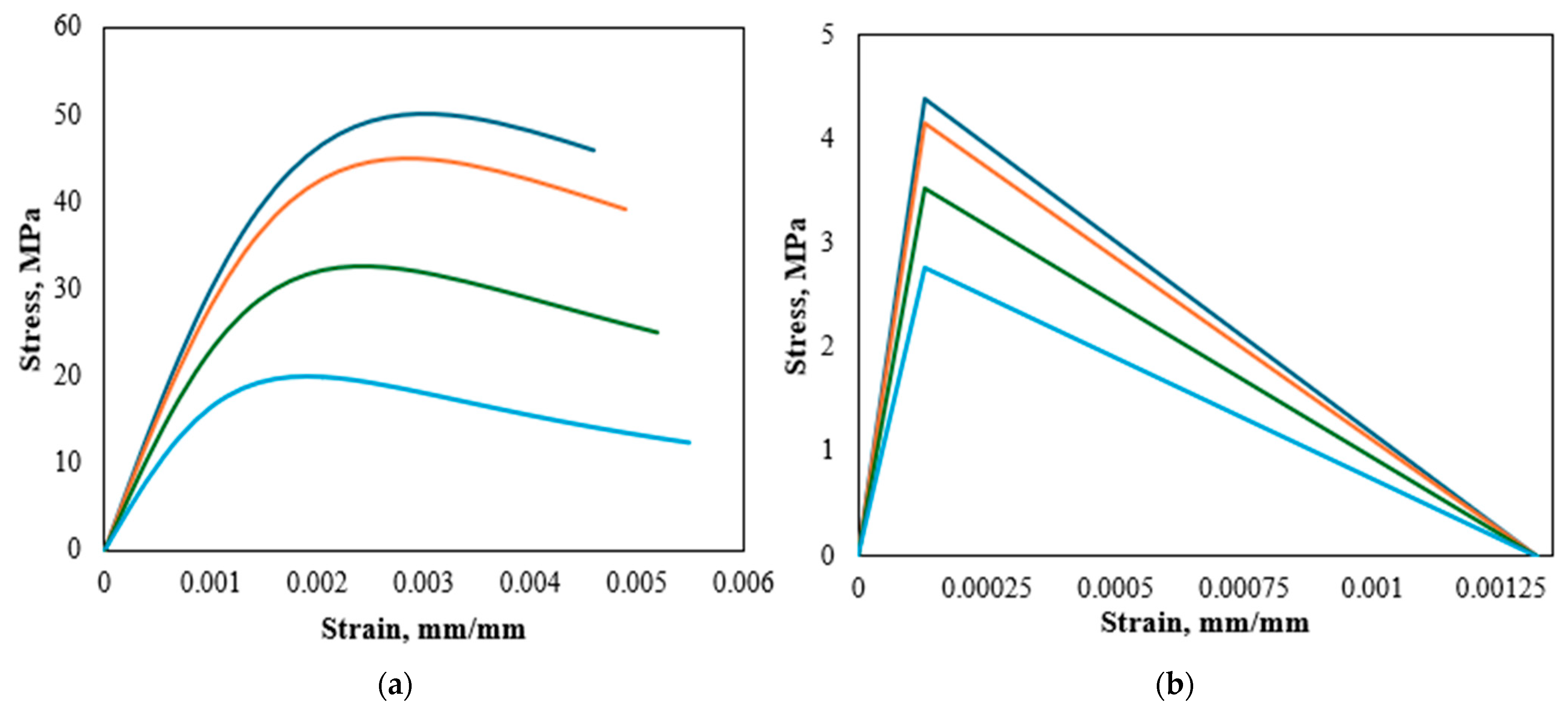
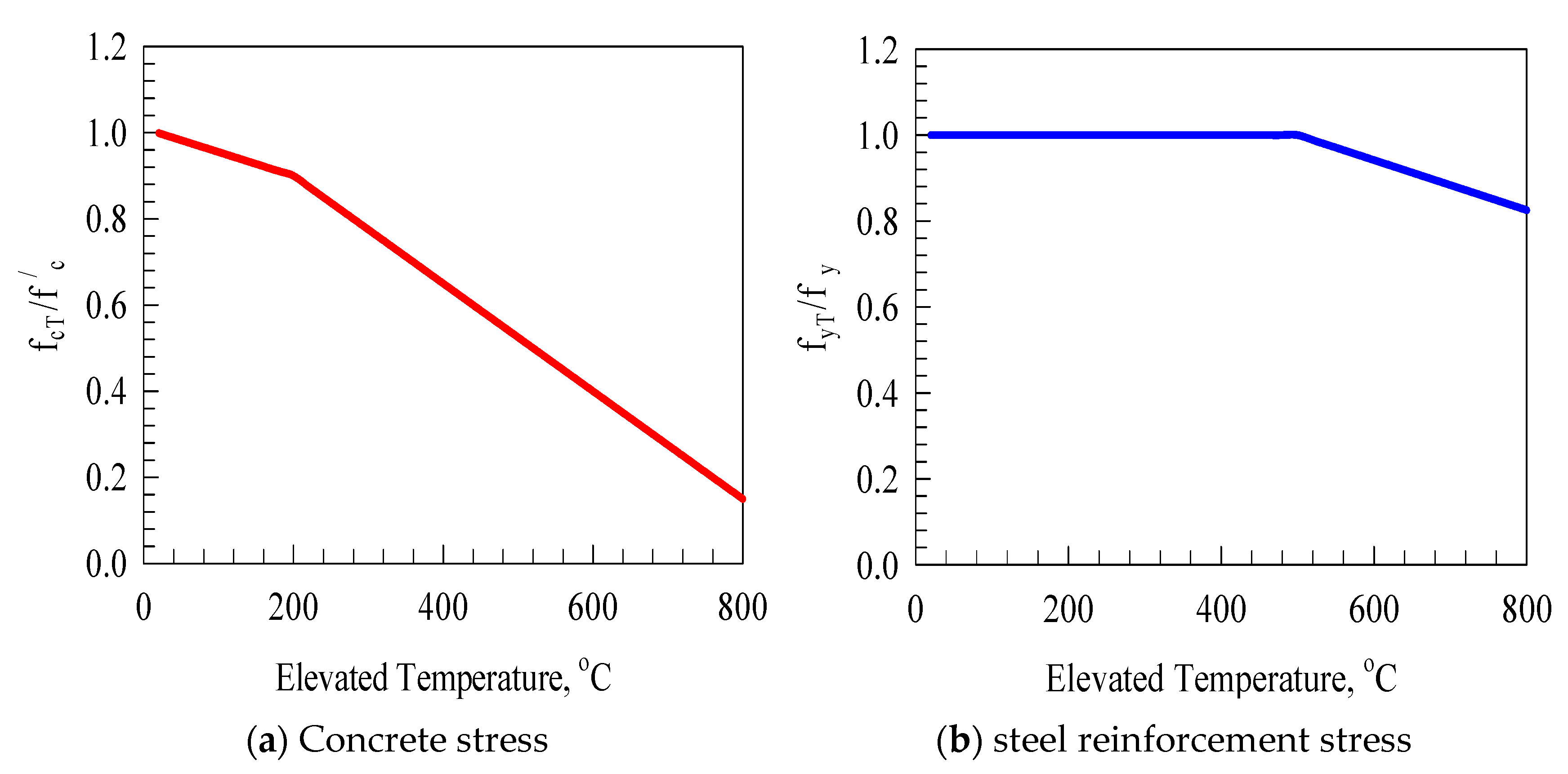
2.2. Material Modeling and Element Types

The concrete compression behavior was defined using the Eurocode 2 (EC2) [23], where the overall stress-strain curve could be fully plotted using the proposed theoretical equations. The concrete modules of elasticity ( E c m ) , and the Poisson’s ratio ( υ ) were also defined. Mentioning that the concrete compressive strength ( f c m ) depends on the test temperature. The EC2 code equations are illustrated in Equations (1)–(5) [23].
σ c = [ k η η 2 1 + ( k 2 ) η ] f c m
η = ε c ε c 1
k = 1.05   E c m ε c 1 f c m
ε c 1 ( ) = 0.7 ( f c m ) 0.31 2.8
E c m = 22 ( 0.1 f c m ) 0.3
The behavior of concrete material under compression forces is illustrated in Figure 2a, where ( ε c 1 ) and ( ε c u 1 ) are the strain values corresponding to the ultimate and fracture strengths, respectively. The stress-strain curve starts with linear elastic behavior until the stress is 40% of the ultimate strength capacity. In addition, the concrete behavior under tensile stresses is linear elastic with increasing behavior until the cracking strain is reached ( ε c r ) . After that, the tensile strength decreases until no tensile strength can be carried by concrete, equal to ten times the cracking strain, as shown in Figure 2b. Concrete was modeled using the bilinear plane stress element with four nodes and full integration elements having two degrees of freedom at each node. Furthermore, concrete compressive strength is reduced under elevated temperatures and simulated as given by Chang et al. [31], as shown in Figure 3a.
Steel material was modeled using the T2D2 truss element with two-dimensional only, with each node having two degrees of freedom. In addition, it has been mentioned that the shear key is very small, so no reinforcement could be provided. However, reinforcement is required for the two connected parts in the segmental bridge. Steel rebars with 12 mm diameter were used to ensure the failure occurrence within the key itself [39]. An elastic perfectly plastic behavior was assumed with 210 GPa elastic modulus, 400 MPa yield strength, and 0.3 Poisson’s ratio. The reduction in the steel reinforcement rebar characteristics was adopted from Tao et al. [40], as shown in Figure 3b.

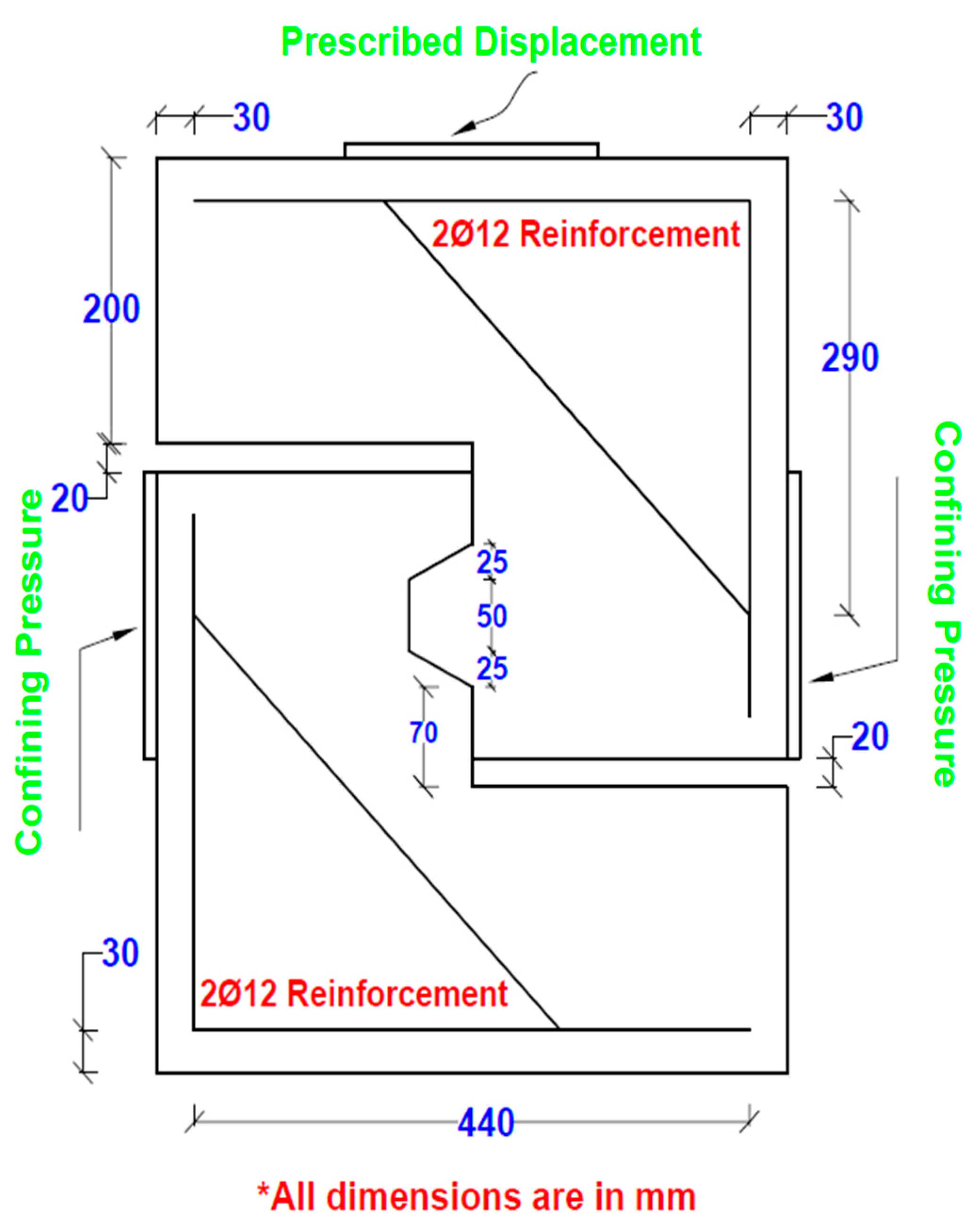
2.3. Constraints, Boundary, and Loading Conditions

The plane shear region was modeled using the node-to-surface contact available in the ABAQUS library with a small sliding option representing the relative displacement between the two parts with a hard contact option to minimize the computational time as much as possible. The friction coefficient at the hard contact plane was taken as 0.72, as proposed by Zhou et al. [6]. In addition, an embedded constraint was also assumed between the concrete and steel reinforcements where the two materials share the same node and move with the same magnitude and direction [41]. In addition, models were fully restrained against all rotational and translational movements. ABAQUS modeling introduced two main steps, including the initial conditions and the lateral confinement pressure steps generated by the post-tensioning application. Finally, damping factor loading is applied as a displacement control at the top of the specimens with 0.0002. A mesh convergence study was carried out for the M1-D-K1-1, where the load strength and stiffness predictions were compared, as appeared in Table 1. Three meshes were selected representing coarse, medium, and fine mesh sizes introduced in Table 1 using the number of resulting elements. The optimum mesh was chosen based on the minimum error percentages for the load and stiffness values.

2.4. Parametric Study and the Investigated Parameters
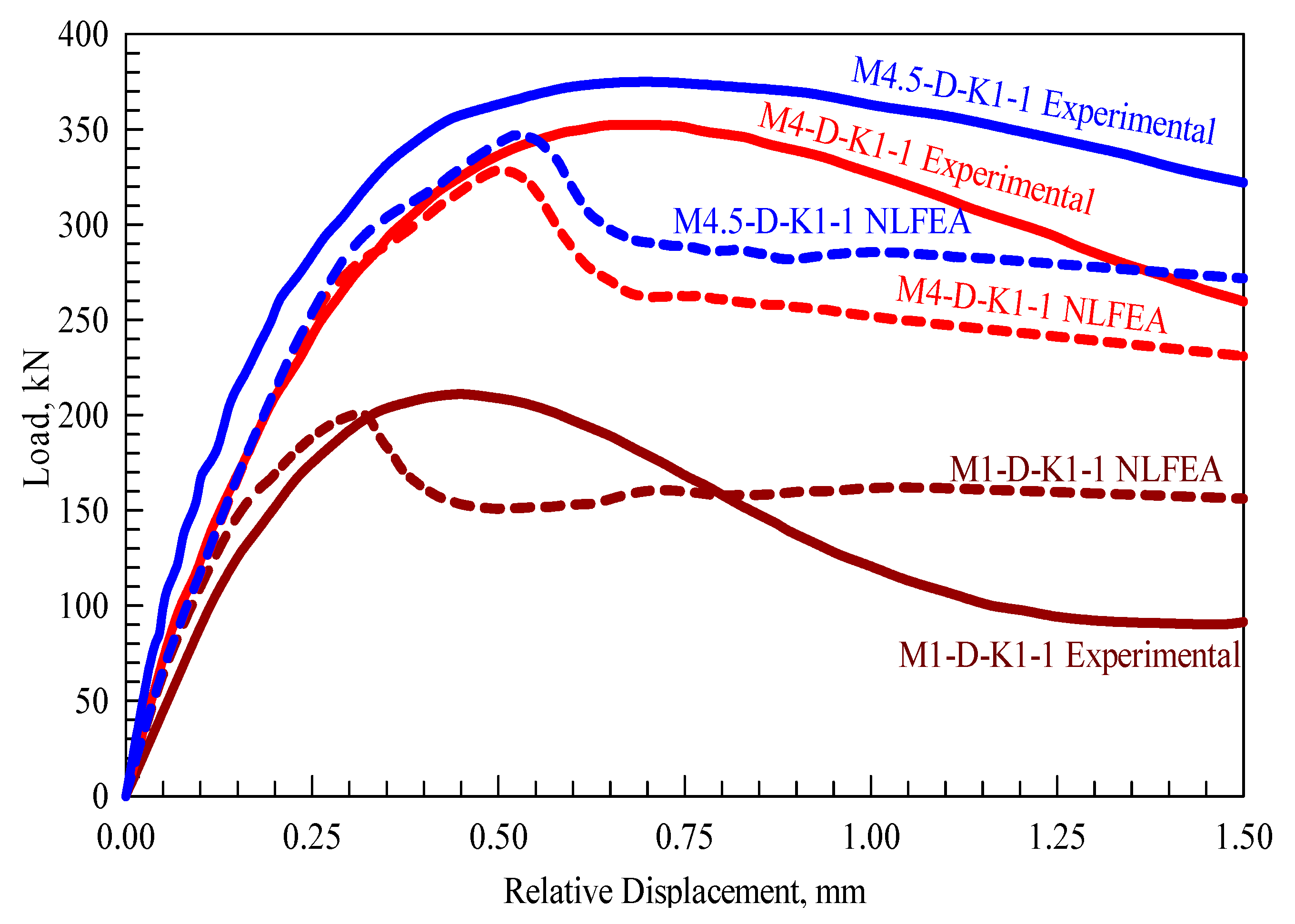
The effect of the lateral confinement pressure and the temperature values were studied during the parametric study stage. Six confinement levels (1, 2, 3, 4, 5, and 6) MPa and four temperatures (23, 200, 400, and 600) °C were examined using twenty-four NLFEA models illustrated in Table 2. Results were reported in terms of failure modes, cracking propagation, and load-deflection characteristics. Specimens’ designation has the first letter “M” representing the monotonic loading, the second letter KJ representing the key joints, the third one with its following number represents the test temperature, and the final one with the following number stands for the confinement pressure value in MPa (M-KJ-T23-C1).
The parameters investigated and their associated values were selected based on their expected influence on the structural system and their contribution toward the shear capacity of the segmental joints. The chosen temperature values include normal and high values (23, 200, 400, and 600) °C. The ambient temperature ( 23   ° C ) was included as a reference to highlight the high-temperature effect on the joint’s performance. In addition, the inclusion of the ( 200   ° C ) was to address the minor concrete degradation effect while the ( 400   ° C ) was to address the high concrete degradation. Finally, the ( 600   ° C ) was included to highlight the combined concrete and steel degradation upon the high-temperature exposure. Moreover, the confinement levels were also selected to have high- and low-pressure effects.

2.5. Validation

The validation stage for the NLFEA models was performed by comparing the cracking propagation, cracking load, failure modes, ultimate strength, and their corresponding deflection values between the simulated and the experimental values, where minor differences of between 1% and 10% minimum and maximum values were recorded. In addition, the cracking patterns and the final % failure modes agreed with each other. Three main types of cracks appear, confirming what has been stated by Kaneko et al. [42]. The first one is the S crack initiated within the shear key itself, the second where the S crack extends toward the upper portion of the joint and forms multiple cracks, and the final one is the M crack, which consists of multiple diagonal ones. However, the final failure modes follow the propagation of the three cracking types and end up with concrete crushing, as reported by Jiang et al. [39]. Moreover, validation was performed on the load-deflection curves, as appears in Figure 4. However, fluctuations (up and down) between experimental and NLFEA observed in Figure 4 that could be related to the residual strength existed within the segmental key joints that were observed earlier within the M1-D-K1-1 model compared to the other models that have the residual strength appeared at larger displacement values.

3. NLFEA Results and Discussion

The parametric study used the ABAQUS software based on the validation results and the accuracy in predicting shear key joint behavior. Structural performance characteristics were reported, including the overall load-deflection behavior under different temperature and confinement values. The results have been revealed to confirm what has been reported in the literature.

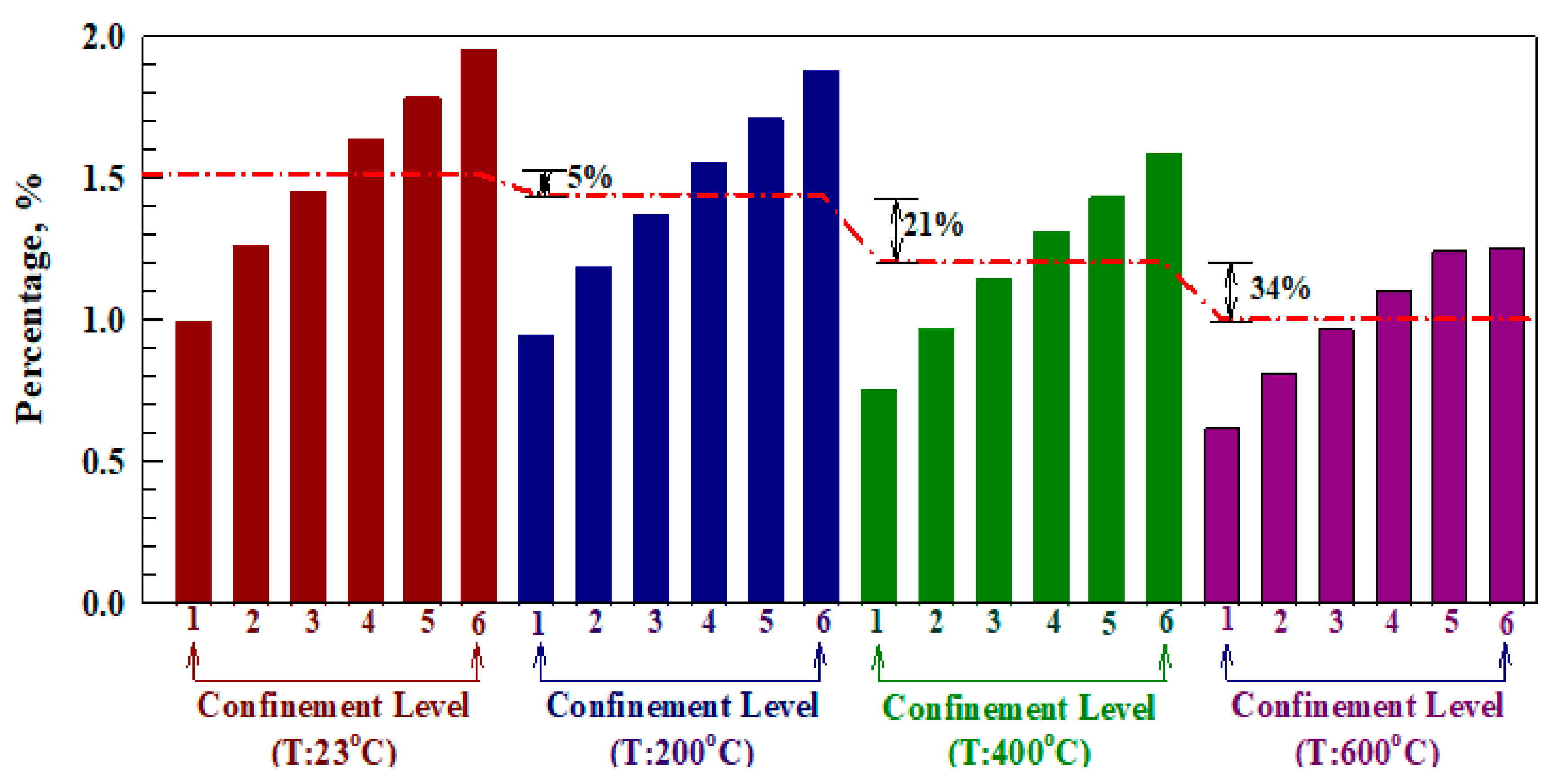
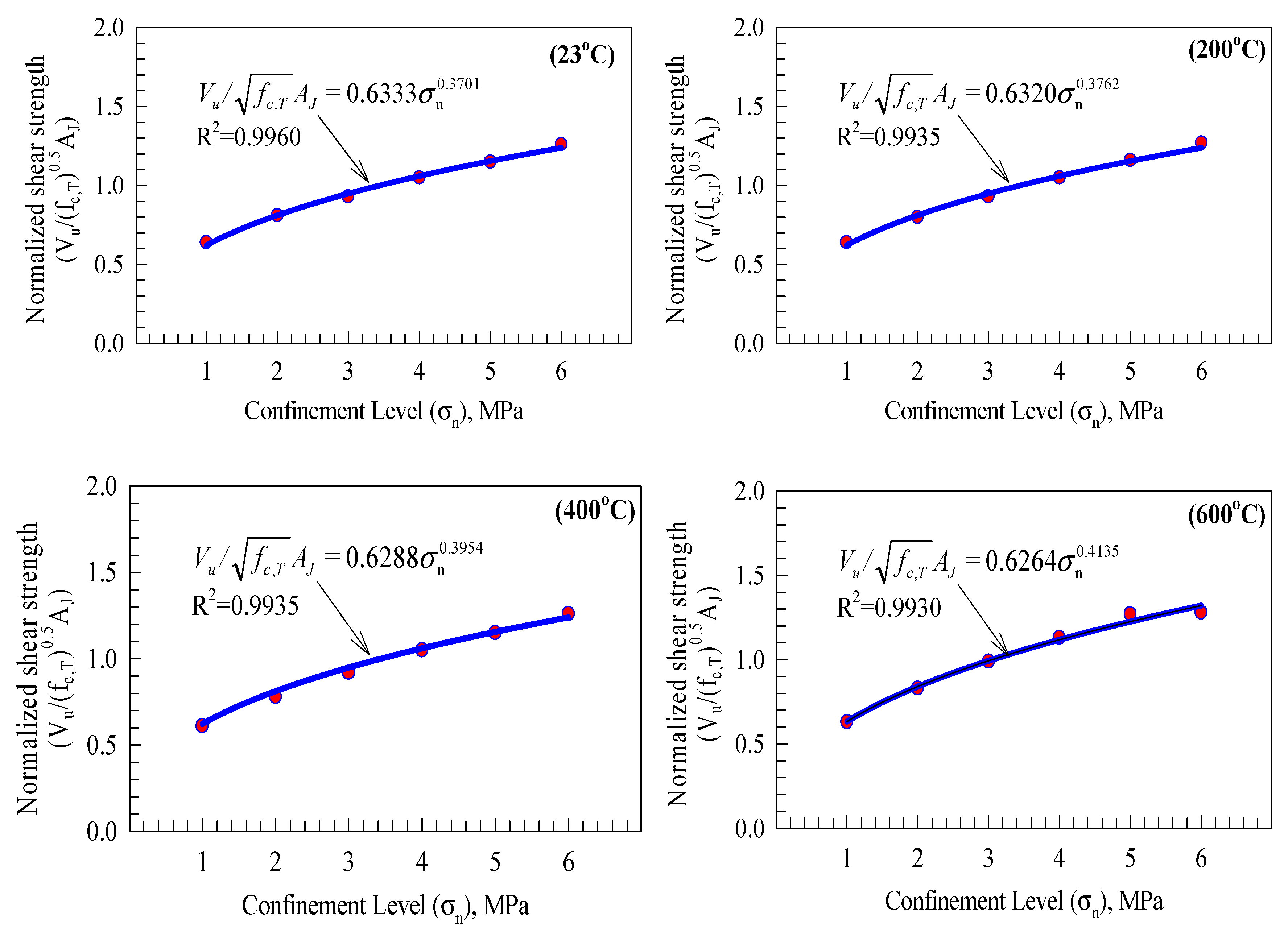
3.1. Shear Strength Capacity

It has been previously stated that the shear strength of the key joint is mainly related to the utilized concrete grade and the applied confinement pressure. The shear strength behavior at the ultimate stage was plotted against the different temperature and confinement pressure values, as shown in Figure 5 for the results presented in Table 2. Results were normalized with respect to a shear key joint tested at ambient temperature with 1 MPa confinement pressure. The ultimate capacity was increased by (26, 45, 64, 78, and 95) % for specimens with confinement pressure values of (2, 3, 4, 5, and 6) MPa, respectively, at ambient temperature. However, increasing the temperature value to 200 °C reduces the ultimate capacity by 5% for 1 MPa confinement compared to the one tested at ambient temperature.
In contrast, increasing the confinement level to (2, 3, 4, 5, and 6) MPa increases the shear strength by (19, 56, 71, and 88) %, respectively, revealing that a minimum confinement pressure of 2 MPa should be provided to maintain the structural behavior at 200 °C. Moreover, increasing the temperature to 400 °C reduces the capacity at 1 and 2 MPa confinement by (24 and 3) %, while the capacity was reduced by (38, 19, and 3) % at confinement pressures of (1, 2, and 3) MPa for joints exposed to 600 ° C temperature. This revealed that a minimum of 3 and 4 MPa confinement pressure is required to maintain the joint behavior after exposure to 400 °C and 600 °C, respectively. In contrast, the capacity was increased by (15, 31, 44, and 59) % under 400 °C for pressure values of (3, 4, 5, and 6) MPa, compared to (11, 25, and 26) % at 600 °C for confinement pressure values of (4, 5, and 6) MPa, respectively. Finally, it could be concluded that the resulting average reduction in the joint’s ultimate shear strength is (5, 21, and 34) % for temperature values of (200, 400, and 600) °C, respectively, compared to ambient temperature.
The associated enhancement in the shear capacity under increasing the confinement pressure was significantly decreased under high temperatures, interpreted by exceeding the material strength by the applied loading at certain levels where no effect is further recorded for increasing the confinement pressure. Shear stress values were normalized with respect to the different concrete compressive strengths by dividing them by the square root of their compressive strength to mitigate their influence on the ultimate shear conclusions, as shown in Figure 6, benefiting from the introduced method in both the AASHTO and the ACI 318-19 codes [8,44]. The results of Figure 6 were introduced at different temperature levels (23, 200, 400, and 600) °C that have a direct effect on the relationships obtained. Observing Figure 6 shows that exponential expressions were obtained in the form of A σ n B . The values for the A parameter were equal to (0.6333, 0.6320, 0.6288, and 0.6264) for temperature values of (23, 200, 400, and 600) °C, respectively, compared to (0.3701, 0.3762, 0.3954, and 0.4135) for the B parameter, respectively. The fitted exponential relationships have R 2 values of (0.9960, 0.9935, 0.9935, and 0.9930), for the four temperature values, respectively, which reveal a very high accuracy level for the expression obtained.

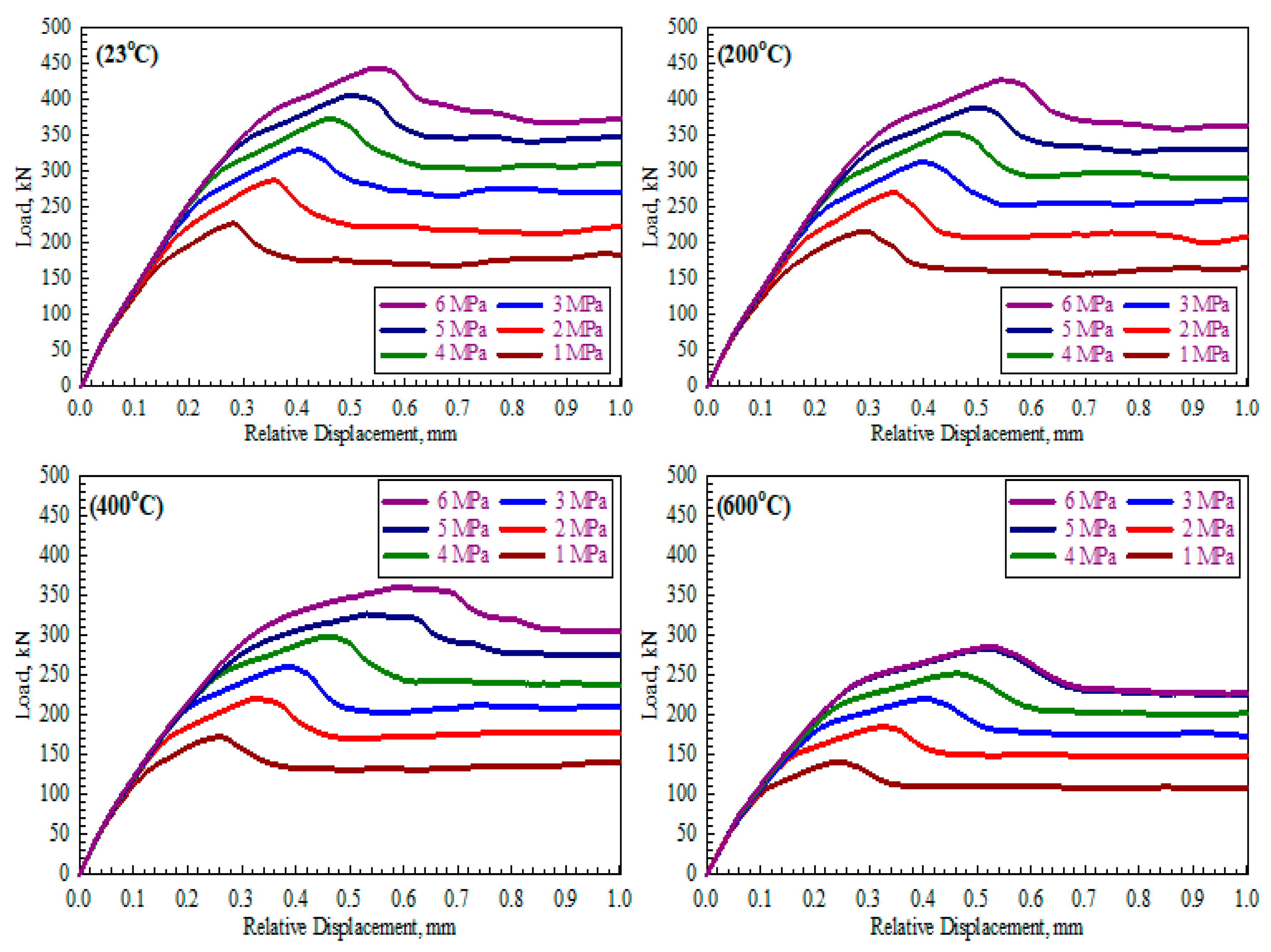
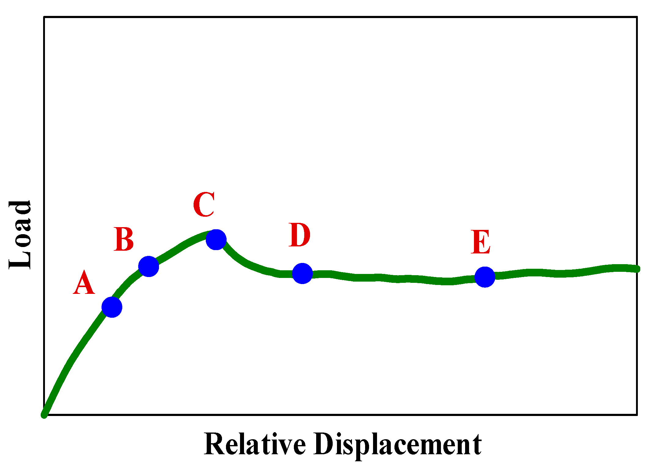
3.2. Load-Displacement Relationship

The load versus the deflection values were plotted for all specimens, as illustrated in Figure 7. Two main load-transferring mechanisms exist within the shear key joints: bearing and friction. However, the separation of the two connected parts might occur once the ultimate strength capacity is reached, where the separation initiates from the joint’s lower corner and extends toward the upper regions, forming the well-known shearing-off phenomenon. At this point, a sudden reduction in the sustained load appears as a drop in the load-deflection curves, and the residual strength that comes from the tangential frictional forces is the only one responsible for the amount of load sustained post-failure and increases as the confinement pressure is increased [12].
Generally, increasing the applied confinement pressure increases the shear strength capacity of the simulated joint while increasing the temperature value reduces the ultimate strength value. Increasing the confinement pressure from 1 MPa to 6 MPa increases the residual strength but depends mainly on the concrete compressive strength. In addition, the ultimate deflection is decreased by increasing the confinement pressure, while the initial stiffness is increased, as per Figure 7, confirmed by Buyukozturk et al. [45] conclusions.

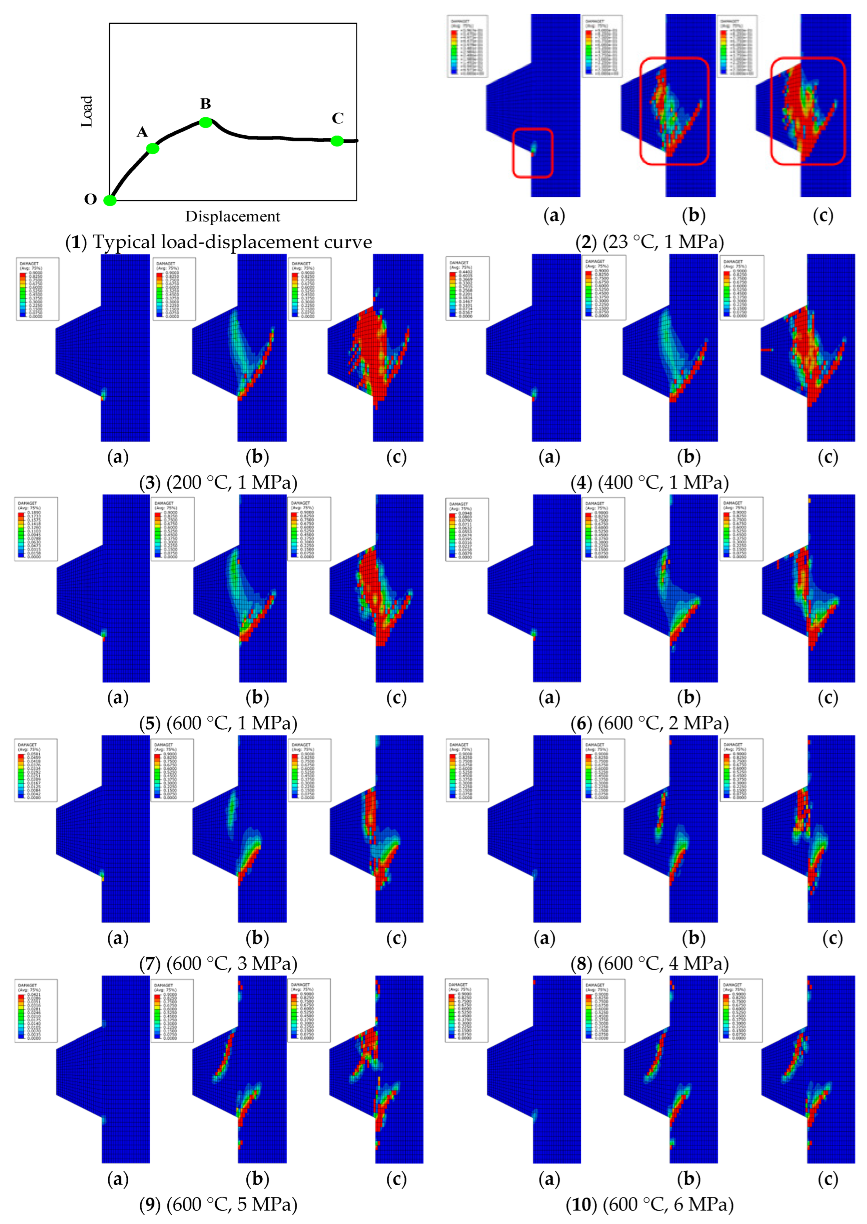
3.3. NLFEA Cracking and Concrete Damage Behavior

The load-deflection curve behavior could be mainly divided into three main stages, as per Figure 8(1). The first one is the linear elastic part that extends between the O and A points and ends with the concrete material cracking (Figure 8(2a)), where the nonlinear behavior appears within the second stage up to point B associated with the propagation of the tensile damage toward the upper regions (Figure 8(2b)). The final stage is between the B and C points, where no load can be sustained, and the joint reaches the maximum capacity, forming a diagonal inclined crack that extends along the shear plane at approximately 45 degrees, as per (Figure 8(2c)). In addition, the final failure damage patterns decreased with increasing confinement level pressures. The resulting NLFEA cracking behavior agrees with the experimentally tested ones, revealing the reliability and predictability of the simulated models in providing the actual structural behavior of the shear key joints.

3.4. Crack Pattern

The detailed cracking propagation with their corresponding parts from the load-deflection curve is presented in Figure 9. Cracking is initiated once the concrete principal tensile strain values exceed the cracking strain for the utilized concrete material, depending on its grade, and failure occurs once the strain exceeds the failure or fracture strain value, given by the EC2 code [23] as 0.0035 and approximately equals to ten times the cracking strain value. The NLFEA and experimental cracking propagation stages look similar, revealing the simulation models’ reliability and accuracy in capturing the exact behavior of shear key joints. Cracking begins within the joint’s lower corner and extends diagonally at 45 degrees until the upper parts of the joint are reached, where the S cracks appear, corresponding to about 70% of the joint’s ultimate shear capacity, that is completely formed once the maximum capacity is reached, followed by the appearance of multiple M cracks. After that, the multiple cracks are interconnected and form one large vertical crack within the shear key failure plane, which ends with separating the connected parts by the shearing-off phenomenon, confirmed by the observed concrete spalling behavior in the experimental work of Zhou et al. [6].

4. New Theoretical Punching Shear Model

The shear strength capacity is related to the concrete compressive strength ( f c ) , as stated by Buyukozturk et al. [45], besides the prestressing force ( σ n ) and the join’s area ( A j ) , as illustrated in Equation (6). However, it has been stated in the literature that the AASHTO [8] equation given by Equation (7) results in very conservative results in terms of the joint’s bearing and smooth contact area ( A k   and   A s m ) . In addition, the ATEP Spanish code for designing concrete structures proposes a formula that appears in Equation (8), including the effect of the concrete strength under compressive stresses, the total area of the contact joint, and the applied prestressing stress ( f c d ,     A j ,   and   σ n ) :
V u = A j ( 0.647 f c + 1.36 σ n )  
V u = A k f c ( 0.205 σ n + 0.996 ) + 0.6 A s m σ n
V u = A j ( 0.0564 f c d + 1.41 σ n )
The AASHTO [8] equation was revised by Turmo et al. [19] and updated the concrete-related tensile strength term based on wide experimental data, as given in Equations (9) and (10). Moreover, Rombach [1] proposed an equation that considered the effect of friction forces ( μ ) and introduced a 0.2 safety factor ( γ F ) , as per Equation (11).
V u = A k f c k 2 / 3 ( 0.07 σ n + 0.33 ) + 0.6 σ n A s m     f c k 50   MPa
V u = A k   l n ( 1 + 0.1 f c m ) ( 0.49 σ n + 0.233 ) + 0.6 σ n A s m     f c k > 50   MPa
V u = ( μ σ n A j + 0.14 f c A k ) / γ F
From the previously mentioned literature models, it could be stated that different factors affect the shear strength of the shear key joint, including its material and geometrical properties. However, the accurate contribution of each factor has not been properly understood until now, and more investigations are required. It has been mentioned previously that the concrete compressive strength is highly reduced depending on the exposed temperature (T) and given by the term ( f c , T ) proposed by Chang et al. [31], as shown in Equation (12). The concrete confinement level and strength were plotted in Figure 6 against the simulation results to determine these parameters’ effect on the overall shear strength capacity. Moreover, it has been revealed by Hou et al. [21] that the geometrical properties of the shear key do not influence the joint’s shear strength if the friction coefficient is larger than 0.35 and the concrete material properties are the dominant factors. Therefore, the concrete contribution is included within the average normalized shear factor, as shown in Equation (13).
f c , T = { ( 1.01 0.00055 T ) f c m 20   ° C T 200   ° C ( 1.15 0.00125 T ) f c m 200   ° C T 800   ° C }
V u / f c , T A J = α σ n β
Two regression factors were introduced ( α   and   β ) and obtained using the numerical data, as shown in Figure 10. However, after substituting the obtained values, the ultimate shear capacity is calculated as in Equation (14), and the final expression is shown in Equation (15).
V u = ( ( 0.0002 f c , T + 0.6216 ) σ n 0.4459 e 0.004 f c , T ) f c , T A J
V u = { ( ( 0.0002 [ ( 1.01 0.00055 T ) f c m ] + 0.6216 ) σ n 0.4459 e 0.004 f c , T ) f c , T A J   20   ° C T 200   ° C ( ( 0.0002 [ ( 1.15 0.00125 T ) f c m ] + 0.6216 ) σ n 0.4459 e 0.004 f c , T ) f c , T A J 200   ° C T 800   ° C }

4.1. Model Verification Against ABAQUS Results and Existing Formulas

The model accuracy was examined by comparing the predicted values against the numerically obtained ABAQUS results. The results of twenty-four models were compared in Table 3 after normalizing the shear values to exclude the effect of the concrete compressive strength, and the only results were in terms of the lateral confinement pressure. Results were very close, with an average difference percentage of 5%. In addition, the simulated specimen’s shear strength capacity was compared with the other formulas from the literature, as shown in Table 4. However, it has been revealed that increasing the confinement level increases the predicted shear strength by linear relationship for all formulas. The most acceptable predictions were observed by the ATEP and the AASHTO codes [8,22] for confinement pressure values of more than 3 MPa. Finally, the new model resulted in good prediction against the experimentally obtained data by Zhou et al. [6].

4.2. Model Verification Against Experimental Data

Different experimental and numerical data were collected in the literature to comprehensively understand the shear key joints’ behavior [9,45,46,47]. Many factors contributed to the shear strength, making the availability to compare the effect of one parameter very difficult. The experimental selected data were also compared with the AASHTO code prediction [8], as illustrated in Table 5. Good agreement was recorded for the new model and the AASHTO code, with differences between ( 30 %   to + 25 % ) .

5. Conclusions

The effect of the lateral confinement pressure and the temperature value were studied on the structural behavior of single dried shear keys installed within a segmental bridge construction using the NLFEA method by ABAQUS software. A total of twenty-four NLFEA models were built using different material models and properties with proper assumptions. Based on the simulation results, the following could be concluded:
  • The shear strength capacity of the shear key joints is reduced by (5, 21, and 34)% for temperature values of (200, 400, and 600) °C, compared to the specimen’s behavior at ambient temperature.
  • Two main load transfer mechanisms contributed to the shear strength of the key joints: friction and bearing. In addition, the connected regions within the segmental concrete bridges are the concrete cracking and crushing, forming the final failure of the specimens.
  • The cracking load is very high in single-shear key joints, where the final failure occurs after a short time from initiating the first crack. However, the cracking load value is approximately (60–80)% of the specimen’s ultimate capacity.
  • Increasing the lateral confinement pressure reduces the simulated specimens’ stiffness and deflection and increases their ultimate loading capacity at ambient temperature. In contrast, the improvement is limited by the concrete compressive strength, which is significantly degraded at elevated temperatures.
  • The lateral confinement level directly affects the cracking propagation process, where cracks are decreased in length, width, and number until they become invisible at high confinement values.
  • The shear strength capacity predictions of the single shear keys were predicted using different theoretical formulations in the literature based on a wide set of experimental and numerical data along with a new proposed formula, and high accuracy was reached.
  • The proposed shear formula can efficiently predict shear keys’ shear capacity at ambient and elevated temperatures.

Author Contributions

Conceptualization, B.R.A. and R.A.-R.; methodology, B.R.A. and R.A.-R.; formal analysis, B.R.A. and R.A.-R.; investigation, B.R.A. and R.A.-R.; resources, B.R.A. and R.A.-R.; data curation, B.R.A. and R.A.-R.; writing—original draft preparation, B.R.A. and R.A.-R.; writing—review and editing, B.R.A.; visualization, B.R.A. and R.A.-R.; supervision, B.R.A. and R.A.-R.; project administration, B.R.A. and R.A.-R. All authors have read and agreed to the published version of the manuscript.

Funding

This research received no external funding.

Data Availability Statement

The original contributions presented in the study are included in the article, further inquiries can be directed to the corresponding author.

Acknowledgments

This work was fully supported by Jordan University of Science and this support is gratefully acknowledged.

Conflicts of Interest

The authors declare no conflicts of interest.

References

  1. Rombach, G. Precast segmental box girder bridges with external prestressing-design and construction. Segmental Bridges INSA Rennes 2002, 19, 1–15. [Google Scholar]
  2. Al-Rousan, R.Z.; Alnemrawi, B.R. Interaction diagram of rectangular RC columns confined with CFRP composite under biaxial bending. Structures 2025, 75, 108833. [Google Scholar] [CrossRef]
  3. Issa, M.A.; Abdalla, H.A. Structural Behavior of Single Key Joints in Precast Concrete Segmental Bridges. J. Bridge Eng. 2007, 12, 315–324. [Google Scholar] [CrossRef]
  4. Zou, Y.; Xu, D. Mechanical Characteristics of Steel Shear Keyed Joints in the Construction and Finished States. Adv. Civ. Eng. 2021, 2021, 7252122. [Google Scholar] [CrossRef]
  5. Al-Rousan, R.; Alnemrawi, B.R. NLFEA of the Behavior of Polypropylene-Fiber-Reinforced Concrete Slabs with Square Opening. Buildings 2024, 14, 480. [Google Scholar] [CrossRef]
  6. Zhou, X.; Mickleborough, N.; Li, Z. Shear Strength of Joints in Precast Concrete Segmental Bridges. ACI Struct. J. 2005, 102, 3–11. [Google Scholar] [CrossRef]
  7. Alnemrawi, B.R.; Al-Rousan, R. The Detailed Axial Compression Behavior of CFST Columns Infilled by Lightweight Concrete. Buildings 2024, 14, 2844. [Google Scholar] [CrossRef]
  8. AASHTO. Guide Specifications for Design and Construction of Segmental Concrete Bridges 1999; Transportation Officials: Washington, DC, USA, 1999. [Google Scholar]
  9. Yang, I.-H.; Kim, K.-C.; Kim, Y.-J. Shear strength of dry joints in precast concrete modules. In Proceedings of the Thirteenth East Asia-Pacific Conference on Structural Engineering and Construction (EASEC-13), Sapporo, Japan, 11–13 September 2013; pp. 1–5. [Google Scholar]
  10. Li, G.; Yang, D.; Lei, Y. Combined Shear and Bending Behavior of Joints in Precast Concrete Segmental Beams with External Tendons. J. Bridge Eng. 2013, 18, 1042–1052. [Google Scholar] [CrossRef]
  11. Ahmed, G.H.; Aziz, O.Q. Shear strength of joints in precast posttensioned segmental bridges during 1959–2019, review and analysis. Structures 2019, 20, 527–542. [Google Scholar] [CrossRef]
  12. Ahmed, G.H.; Aziz, O.Q. Stresses, deformations and damages of various joints in precast concrete segmental box girder bridges subjected to direct shear loading. Eng. Struct. 2020, 206, 110151. [Google Scholar] [CrossRef]
  13. Pulkit, U.; Adhikary, S.D. Effect of micro-structural changes on concrete properties at elevated temperature: Current knowledge and outlook. Struct. Concr. 2022, 23, 1995–2014. [Google Scholar] [CrossRef]
  14. Chen, J.; Young, B.; Uy, B. Behavior of High Strength Structural Steel at Elevated Temperatures. J. Struct. Eng. 2006, 132, 1948–1954. [Google Scholar] [CrossRef]
  15. Elghazouli, A.Y.; Cashell, K.A.; Izzuddin, B.A. Experimental evaluation of the mechanical properties of steel reinforcement at elevated temperature. Fire Saf. J. 2009, 44, 909–919. [Google Scholar] [CrossRef]
  16. Babalola, O.E.; Awoyera, P.O.; Le, D.H.; Bendezú Romero, L.M. A review of residual strength properties of normal and high strength concrete exposed to elevated temperatures: Impact of materials modification on behaviour of concrete composite. Constr. Build. Mater. 2021, 296, 123448. [Google Scholar] [CrossRef]
  17. Zhao, J.; Jiang, Y.; Li, X. Flexural behavior of concrete beams reinforced with high-strength steel bars after exposure to elevated temperatures. Constr. Build. Mater. 2023, 382, 131317. [Google Scholar] [CrossRef]
  18. Algorafi, M.A.; Ali, A.A.A.; Othman, I.; Jaafar, M.S.; Anwar, M.P. Experimental study of externally prestressed segmental beam under torsion. Eng. Struct. 2010, 32, 3528–3538. [Google Scholar] [CrossRef]
  19. Turmo, J.; Ramos, G.; Aparicio, A.C. Shear strength of dry joints of concrete panels with and without steel fibres: Application to precast segmental bridges. Eng. Struct. 2006, 28, 23–33. [Google Scholar] [CrossRef]
  20. Alcalde, M.; Cifuentes, H.; Medina, F. Influence of the number of keys on the shear strength of post-tensioned dry joints. Mater. Construcción 2013, 63, 297–307. [Google Scholar] [CrossRef]
  21. Hou, W.; Peng, M.; Jin, B.; Tao, Y.; Guo, W.; Zhou, L. Influencing Factors and Shear Capacity Formula of Single-Keyed Dry Joints in Segmental Precast Bridges under Direct Shear Loading. Appl. Sci. 2020, 10, 6304. [Google Scholar] [CrossRef]
  22. del Pozo Vindel, F.J. Información sobre ATEP (Asociación Técnica Española del Pretensado), GEHO (Grupo Español del Hormigón), FIP (Federación Internacional del Pretensado) y CEB (Comité Eurointernacional del Hormigón). Hormigón Y Acero 1996, 202, 9–12. [Google Scholar]
  23. EC2. Eurocode 2: Design of Concrete Structures—Part 1-1: General Rules and Rules for Buildings; British Standard Institution: London, UK, 2004. [Google Scholar]
  24. Liu, T.; Wang, Z.; Guo, J.; Wang, J. Shear Strength of Dry Joints in Precast UHPC Segmental Bridges: Experimental and Theoretical Research. J. Bridge Eng. 2019, 24, 04018100. [Google Scholar] [CrossRef]
  25. Al-Rousan, R.Z.; Alnemrawi, B.R. Empirical and precise finite element modelling of bond-slip contact behavior between heat-damaged concrete and anchored CFRP composites with groove. Eng. Struct. 2025, 332, 120042. [Google Scholar] [CrossRef]
  26. Alnemrawi, B.R.; Al-Rousan, R.Z. Finite-element based-prediction of the cracking-torsional behavior of prestressed concrete beams with hollow cross-sections. Results Eng. 2025, 25, 103712. [Google Scholar] [CrossRef]
  27. Alnemrawi, B.R.; Al-Rousan, R.Z. Flexural performance of NSM and PNSM beams maintaining the ACI440 bar diameter to groove size limitation. Results Eng. 2025, 25, 104570. [Google Scholar] [CrossRef]
  28. Al-Rousan, R.Z.; Alnemrawi, B.R. Impact of the size effect and CFRP ratio on NLFEA shear behavior of CFRP-strengthened RC deep beams without stirrups. Constr. Build. Mater. 2025, 458, 139777. [Google Scholar] [CrossRef]
  29. Kim, T.-H.; Kim, Y.-J.; Jin, B.-M.; Shin, H.-M. Numerical study on the joints between precast post-tensioned segments. Int. J. Concr. Struct. Mater. 2007, 19, 3–9. [Google Scholar] [CrossRef]
  30. Turmo, J.; Ramos, G.; Aparicio, A. Towards a model of dry shear keyed joints: Modelling of panel tests. Comput. Concr. 2012, 10, 469–487. [Google Scholar] [CrossRef]
  31. Chang, Y.F.; Chen, Y.H.; Sheu, M.S.; Yao, G.C. Residual stress–strain relationship for concrete after exposure to high temperatures. Cem. Concr. Res. 2006, 36, 1999–2005. [Google Scholar] [CrossRef]
  32. Manica, G.C.; Bolina, F.L.; Tutikian, B.F.; Oliveira, M.; Moreira, M.A. Influence of curing time on the fire performance of solid reinforced concrete plates. J. Mater. Res. Technol. 2020, 9, 2506–2512. [Google Scholar] [CrossRef]
  33. Nielsen, M.P.; Hoang, L.C. Limit Analysis and Concrete Plasticity; CRC Press: Boca Raton, FL, USA, 2016. [Google Scholar]
  34. Hsu, J.-H.; Lin, C.-S. Effect of Fire on the Residual Mechanical Properties and Structural Performance of Reinforced Concrete Beams. J. Fire Prot. Eng. 2008, 18, 245–274. [Google Scholar] [CrossRef]
  35. ABAQUS. ABAQUS Analysis User’s Guide, Version 6.14; Dassault Systemes Simulia Corp.: Cleveland, OH, USA, 2014. [Google Scholar]
  36. Kmiecik, P.; KamiŃSki, M. Modelling of reinforced concrete structures and composite structures with concrete strength degradation taken into consideration. Arch. Civ. Mech. Eng. 2011, 11, 623–636. [Google Scholar] [CrossRef]
  37. Wai, C.; Rivai, A.; Bapokutty, O. Modelling optimization involving different types of elements in finite element analysis. IOP Conf. Ser. Mater. Sci. Eng. 2013, 50, 012036. [Google Scholar] [CrossRef]
  38. Shamass, R.; Zhou, X.; Alfano, G. Finite-Element Analysis of Shear-Off Failure of Keyed Dry Joints in Precast Concrete Segmental Bridges. J. Bridge Eng. 2015, 20, 04014084. [Google Scholar] [CrossRef]
  39. Jiang, H.; Chen, L.; Ma, Z.J.; Feng, W. Shear Behavior of Dry Joints with Castellated Keys in Precast Concrete Segmental Bridges. J. Bridge Eng. 2015, 20, 04014062. [Google Scholar] [CrossRef]
  40. Tao, Z.; Wang, X.-Q.; Uy, B. Stress-Strain Curves of Structural and Reinforcing Steels after Exposure to Elevated Temperatures. J. Mater. Civ. Eng. 2013, 25, 1306–1316. [Google Scholar] [CrossRef]
  41. Garg, A.K.; Abolmaali, A. Finite-Element Modeling and Analysis of Reinforced Concrete Box Culverts. J. Transp. Eng. 2009, 135, 121–128. [Google Scholar] [CrossRef]
  42. Kaneko, Y.; Connor, J.J.; Triantafillou, T.C.; Leung, C.K. Fracture Mechanics Approach for Failure of Concrete Shear Key. I: Theory. J. Eng. Mech. 1993, 119, 681–700. [Google Scholar] [CrossRef]
  43. Al-Rousan, R.Z.; Qudaisat, M.S. Single keyed joints behaviour and capacity formulation under direct shear using non-linear finite-element analysis. Structures 2023, 47, 911–924. [Google Scholar] [CrossRef]
  44. Committee, A. Building Code Requirements for Reinforced Concrete and Commentary; American Concrete Institute: Farmington Hills, MI, USA, 2019. [Google Scholar]
  45. Buyukozturk, O.; Bakhoum, M.M.; Beattie, S.M. Shear Behavior of Joints in Precast Concrete Segmental Bridges. J. Struct. Eng. 1990, 116, 3380–3401. [Google Scholar] [CrossRef]
  46. Jiang, H.; Wei, R.; Ma, Z.J.; Li, Y.; Jing, Y. Shear Strength of Steel Fiber-Reinforced Concrete Dry Joints in Precast Segmental Bridges. J. Bridge Eng. 2016, 21, 04016085. [Google Scholar] [CrossRef]
  47. Jiang, H.; Li, Y.; Liu, A.; Ma, Z.J.; Chen, L.; Chen, Y. Shear Behavior of Precast Concrete Segmental Beams with External Tendons. J. Bridge Eng. 2018, 23, 04018049. [Google Scholar] [CrossRef]
Figure 1. Single dry keyed joint [6].
Buildings 15 01890 g001
Figure 2. (a) Concrete stress-strain diagram in compression [23], (b) Linear stress-strain curve of concrete in tension [23].
Buildings 15 01890 g002
Figure 3. Concrete stress and steel reinforcement stress [31].
Buildings 15 01890 g003
Figure 4. Experimental and numerical load-displacement curves [43].
Buildings 15 01890 g004
Figure 5. Ultimate load percentages versus investigated parameters.
Buildings 15 01890 g005
Figure 6. Normalized shear strength versus confinement from numerical analysis.
Buildings 15 01890 g006
Figure 7. Applied load versus relative vertical displacement.
Buildings 15 01890 g007
Figure 8. Failure modes propagation (a) (O to A) points; (b) (A to B) points; (c) (B to C) points.
Buildings 15 01890 g008
Figure 9. Tensile Strain Development in Concrete [43].
Buildings 15 01890 g009
Figure 10. Regression analysis coefficients (α and β).
Buildings 15 01890 g010
Table 1. Mesh convergence results for the M1-D-K1-1 model.
Number of ElementsLoad, kN | E r r o r   % | Stiffness, kN/mm | E r r o r   % |
20,872200.594.93923.543.78
12,433235.7811.741006.5213.09
74,225274.1129.901254.2640.93
Table 2. Keyed joint details.
Keyed Joint DesignationTemperature, °CConfinement Level, MPaConcrete Compressive Strength, MPaUltimate Load, kNUltimate Stress (σu), MPa τ u / f c , T
KJ-T23-C123150.0226.964.540.64
KJ-T23-C2250.0287.055.740.81
KJ-T23-C3350.0329.796.600.93
KJ-T23-C4450.0372.457.451.05
KJ-T23-C5550.0405.028.101.15
KJ-T23-C6650.0443.608.871.25
KJ-T200-C1200145.0216.184.320.64
KJ-T200-C2245.0270.005.400.80
KJ-T200-C3345.0312.546.250.93
KJ-T200-C4445.0353.697.071.05
KJ-T200-C5545.0388.097.761.16
KJ-T200-C6645.0426.298.531.27
KJ-T400-C1400132.5172.593.450.61
KJ-T400-C2232.5220.924.420.78
KJ-T400-C3332.5260.995.220.92
KJ-T400-C4432.5298.265.971.05
KJ-T400-C5532.5326.586.531.15
KJ-T400-C6632.5360.487.211.26
KJ-T600-C1600120.0141.002.820.63
KJ-T600-C2220.0184.723.690.83
KJ-T600-C3320.0220.434.410.99
KJ-T600-C4420.0252.145.041.13
KJ-T600-C5520.0283.145.661.27
KJ-T600-C6620.0285.245.701.28
Table 3. Numerical versus the proposed equation (Equation (15)) results.
Keyed Joint DesignationTemperature, °CConfinement Level, MPaConcrete Compressive Strength (fcT), MpaNLFEA Ultimate Load,
Vu, kN
Equation (15) Ultimate Load,
Vu, kN
| E r r o r   % |
KJ-T23-C123150.0226.96223.001.8
KJ-T23-C2250.0287.05287.250.1
KJ-T23-C3350.0329.79333.101.0
KJ-T23-C4450.0372.45370.010.7
KJ-T23-C5550.0405.02401.430.9
KJ-T23-C6650.0443.60429.083.4
KJ-T200-C1200145.0216.18211.512.2
KJ-T200-C2245.0270.00273.811.4
KJ-T200-C3345.0312.54318.441.9
KJ-T200-C4445.0353.69354.460.2
KJ-T200-C5545.0388.09385.180.8
KJ-T200-C6645.0426.29412.243.4
KJ-T400-C1400132.5172.59179.043.6
KJ-T400-C2232.5220.92234.865.9
KJ-T400-C3332.5260.99275.275.2
KJ-T400-C4432.5298.26308.093.2
KJ-T400-C5532.5326.58336.222.9
KJ-T400-C6632.5360.48361.090.2
KJ-T600-C1600120.0141.00139.890.8
KJ-T600-C2220.0184.72186.080.7
KJ-T600-C3320.0220.43219.870.3
KJ-T600-C4420.0252.14247.511.9
KJ-T600-C5520.0283.14271.334.4
KJ-T600-C6620.0285.24292.472.5
Table 4. Shear strength predictions.
Designation [6] Shear   Strength   Prediction   | E r r o r   % |
(Equation (15))BuyukozturkAASHTORombachTurmoATEP
M1-D -K1-11961.5339.3812.9549.616.74
M1-D -K1-22235.3840.761.4239.740.47
M3-D -K1-23309.0919.4425.5660.003.06
M4-D -K1-13268.5932.4926.5553.919.32
M4.5-D-K13449.0134.6725.8750.6013.07
Average value6.7233.3518.4750.776.53
Table 5. Experimental and predicted shear strength of dry single-keyed joints.
ReferenceSpecimenConcrete Strength
(MPa)
Confinement
(MPa)
Shear Plane Area
(AJ) (mm2)
ExperimentalEquation (15)AASHTO
V u ( E x p )
(kN)
V u ( E q n ) (kN) V u ( E q n ) V u ( E x p ) V u ( A A S H ) (kN) V U ( A A S H ) V u ( E x p )
[45]Keyed Dry-0.69 MPa48.40.6919,35565.580.61.2365.30.99
Keyed Dry-2.07 MPa47.62.0719,35584.2105.61.2584.20.99
Keyed Dry-3.45 MPa49.43.4519,355111.0133.91.21116.41.05
[10]S60-H10-P164.01.0017,00075.587.31.1670.60.94
S60-H10-P264.02.0017,000105.0106.21.0187.70.84
S60-H10-P364.03.0017,000130.9125.20.96104.70.80
S70-H10-P164.01.0017,00086.387.31.0170.60.82
S70-H10-P264.02.0017,000107.9106.20.9887.70.81
S70-H10-P364.03.0017,000135.0125.20.93104.70.78
S70-H20-P164.01.0017,00086.587.31.0170.60.82
S70-H20-P364.03.0017,000111.8125.21.12104.70.94
[46]K1-N7-F-0.558.30.5020,000117.687.40.7486.30.73
K1-N7-F-1.058.31.0020,000138.798.10.7197.10.70
K1-N7-F-2.058.32.0020,000167.3119.40.71118.60.71
[47]K1-0141.51.0020,00089.782.70.9296.91.08
K1-0241.52.0020,000113.9100.70.88126.41.11
K1-0340.81.0020,00090.882.00.9089.00.98
K1-0440.81.0020,00094.582.00.87107.71.14
Disclaimer/Publisher’s Note: The statements, opinions and data contained in all publications are solely those of the individual author(s) and contributor(s) and not of MDPI and/or the editor(s). MDPI and/or the editor(s) disclaim responsibility for any injury to people or property resulting from any ideas, methods, instructions or products referred to in the content.

