1. Introduction
Chilled water systems are widely used in large-scale air conditioning projects around the world. Pumps circulating chilled water are major energy consumers, responsible for about 15–30% of the system’s energy consumption [
1]. A chilled water system is an all-water system. The chilled water is produced in the central plant and flows through the fan coil unit (FCU), where it absorbs sensible and latent heat from the passing air. The air is cooled and dehumidified after the heat transfer [
2]. The FCUs comprise a finned-tube coil, an insulated drain pan under the coil to collect condensate, a fan to move air through the coil, filters, and a cabinet to house these components. An additional air distribution system may also be employed to distribute only fresh air to meet fresh air requirements [
3].
Past investigations have identified phase change emulsions (PCMEs) as potential working fluids that could be used to reduce energy consumption in HVAC systems [
4,
5,
6,
7]. PCME is a colloidal system in which paraffin is directly dispersed in water by a surfactant, which uses the latent heat capacity of paraffin, as well as the sensible heat capacities of water and PCM, to store thermal energy. PCMEs do not lose fluidity during phase transitions due to the carrier fluid. Hence, PCMEs can be directly used in both storage systems and pumped systems, such as a cold supply network. What is more, without additional coating or supporting materials, a PCME is cheaper to produce and would have a lower viscosity. Integrated PCME/air conditioning systems could take advantage of their high heat capacities to reduce the flow rate, saving pumping power whilst delivering the same cooling effect. PCMEs can also simultaneously act as cold storage materials to shift peak load to off-peak times, improving the COP of systems.
The proposed air conditioning system operates with a chilled-phase change emulsion at a temperature of approximately 7–12 °C. During working hours, the phase change emulsion is directly circulated through a room’s fan coil units by a centrifugal pump, and it completes the phase change process from solid to liquid and extracts heat from the room before returning to the central plant.
In order to model the performance of the proposed system, a modular analysis software, the Transient System Simulation Program 17th (TRNSYS 17th), was applied. The TRNSYS is widely used in central air conditioning system simulation [
8,
9,
10,
11], as well as PCMs [
12,
13,
14]. However, the TRNSYS modules for fan coil units working with PCMEs are not yet mature enough. Therefore, in this paper, a TRNSYS module of a PCME-integrated fan coil unit will be developed and validated first. Then the air conditioning system of an office in Ningbo is simulated based on TRNSYS software.
2. Development of a TRNSYS Model of a Fan Coil Unit Working with a Phase Change Material Emulsion
The key to simulating the effectiveness of the PCME in central air conditioning systems in the TRNSYS is to simulate the heat exchange process between the PCME and air. Therefore, a new TRNSYS component model of a fan coil unit with a PCME as the working fluid was developed and validated first.
2.1. Mathematical Model
A numerical model was used to model fan coil units with phase change emulsions (PCMEs) as the working fluid. The PCME flows through the finned coil and exchanges heat with the air, and the resulting heat exchange process is mainly forced convection.
The fan coil units comprise a finned-tube coil, an insulated drain pan under the coil to collect condensed water vapor, a fan to move air through the coil, filters, and a cabinet to house these components. Therefore, it was modeled as a single equivalent unit made up of the cooling coil (a custom Type 850d component), a variable speed pump (Type 741), and a variable speed fan (Type 662).
Pumps and fans can be modeled using standard components that have already been developed by the TRNSYS Company. However, for all available heat exchangers in the model library, the specific heat capacities of hot-side and cold-side fluids are set as constant parameters. It is not designed to model the phase change effect. Therefore, a custom Type850d component was built to simulate heat exchange with variable heat capacities. Incorporating a forced function block and an effectiveness-NTU method, this component can then be used to model the performance of cross-flow heat exchangers integrated with fluids of variable heat capacities, such as the phase change emulsion.
2.2. Modeling of Heat Exchange
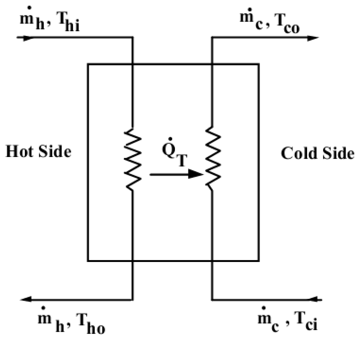
The effective minimum heat capacity rate approach was adopted to model heat exchangers (
Figure 1). In this approach, the heat exchanger’s overall heat transfer coefficient, U, the heat transfer area, A, and inlet conditions shall be provided. The model then determines whether the cold (load) or the hot (source) side is the minimum heat capacity rate side and calculates the effectiveness based on the specified flow configuration and UA.
The effectiveness and outlet conditions of the cross-flow heat exchanger are then computed at each time step using the following equations [
15].
If C
h < C
c, then, C
min = C
h and C
max = C
cIf C
h > C
c, then, C
max = C
h and C
min = Cc,
where
Mc = mass flow rate of the cold side;
Mh = mass flow rate of the hot side;
U = overall heat transfer coefficient;
A = heat transfer area;
Ch = heat capacity rate of the hot side;
Cc = heat capacity rate of the cold side;
ε = effectiveness;
Cmax = maximum value of Ch and CC;
Cmin = minimum value of Ch and CC.
The energy transfer in the coil and outlet temperatures of the hot and cold fluids are as follows:
where subscripts h, c, o, and i represent the hot side, cold side, outlet, and inlet, respectively.
2.3. Modeling the Phase Change Effect
To account for the phase change effect, the effective heat capacity approach was used. It is an approach first introduced by Alisetti et al. [
16], and its accuracy has been validated by other previous theoretical results, as well as experimental data [
17,
18].
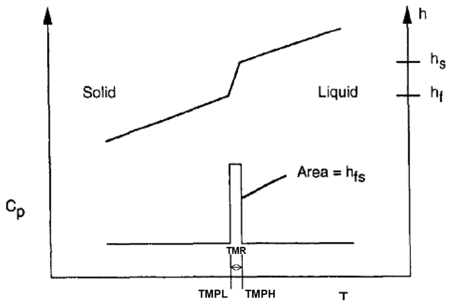
This approach is built on the assumption that the PCM melts over a temperature range, called the phase change temperature range (TMR), so that the phase change effect can be directly incorporated into the energy equation by assuming that the specific heat capacity of the phase change material is a function of the temperature, as
Figure 2 shows. The temperature at which the PCM starts to melt is called the onset-phase change temperature (TMPL), and the temperature at which the PCM starts to solidify is called the end-phase change temperature (TMPH). This avoids complicated terms or special analytical techniques and could easily be applied to the TRNSYS program. The specific heat of the PCM is given according to the temperature based on Equation (9) [
16].
where
Cpm,eff = the effective specific heat of the PCME;
Cp,PCM = the specific heat of paraffin in the solid state;
Δh = the latent heat of fusion;
TMPL = the onset-phase change temperature;
TMPH = the end-phase change temperature.
As the equation shows, outside of the phase change range, the PCM’s specific heat capacity does not vary significantly with temperature, so it can be assumed as a constant. In the phase change range (TMPL < T < TMPH), the specific heat is related to the latent heat of the PCM, which can be measured with suitable analytical tests, such as differential scanning calorimetry (DSC). Though the effective specific heat of the phase change material may vary in the melt temperature range, the shape of the specific heat capacity–temperature curve has little effect on the heat transfer process [
19]. As a result, it is also possible to assume that the specific heat capacity of the PCM remains constant during the phase change process, as
Figure 2 shows.
However, the PCME is a mixture of the PCM and water, so Equation (9) needs to be modified to account for the impact of water. Based on Chen’s research [
20], the specific heat of the emulsion is the mass-averaged specific heat of its constituents. Therefore, the final effective specific heat of the PCME can be described as follows:
where X
PCM is the weight fraction of the PCM.
2.4. Validation of the Developed Model
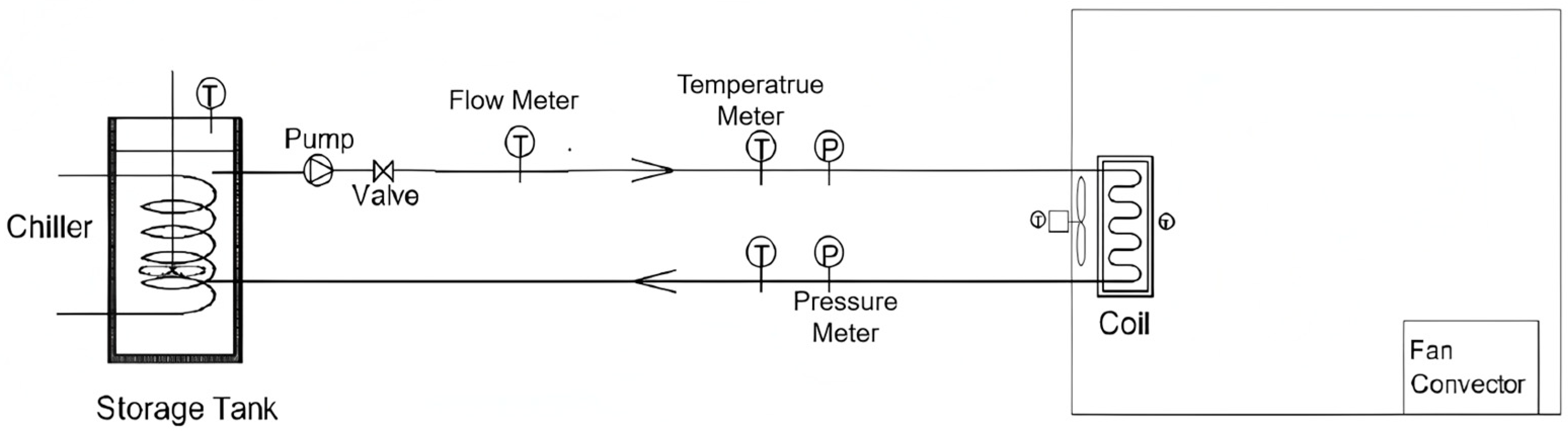
In order to validate the developed mathematical model for the PCME-integrated fan coil units, experimental studies were carried out. A small test rig was constructed in a controlled lab (
Figure 3).
The rig is designed to reproduce a typical FCU installation in an office building. The model space is housed inside a controlled lab, which acts as a buffer to control heat loss and gain through the fabric. The air flow velocity is controlled by adjusting the speed of the fan. Energy is introduced into the test facility using a 500 W heat convector that simulates internal heat gains (people and electrical equipment). The volume flow rate of the PCME was measured at the inlet of the FCU with an accuracy of ±0.1%. The PCME’s temperature and the temperature at the inlet and outlet cross-sections of the air flow were also measured at the coil inlet and outlet by K-type thermocouples with an accuracy of ±0.07%. The pressure drop was measured by two pressure sensors with an accuracy of ±1.5%. The air velocity was measured at the inlet and outlet flow cross-sections with a TESTO anemometer 410-1, whose accuracy is ±2%. A standard FP-34 fan coil unit was used, and its specifications were measured on-site before the experiment, as listed in
Table 1.
During the experiment, the air flow velocity was set at 1 m/s. The temperature of the box was allowed to float between 25–28 °C. The PCME was fabricated according to published work [
20]. The developed phase change emulsion, PCE-10, has a specific heat capacity of 3.8 kJ/(kg·K). During the phase change (TMPL = 4 °C, and TMPH = 11 °C), the specific heat capacity increases to 8.12 kJ/(kg
·K).
The measured results are listed in
Table 2. In
Table 2, the cooling capacity is the average of the air-side and fluid-side capacities [
8], as shown in Equation (11).
This is considered reliable only if the difference between the air- and water-side capacities is less than 5%, as Equation (12) states.
The experimental results are listed in
Table 3. It can be seen from this table that the cooling media flow rate for water is 304 kg/h, while for the PCME, it is 130 kg/h; however, the cooling capacity remains comparable. This result is promising and relates to the contribution of the PCME’s latent heat storage.
To validate the accuracy of the developed model, initial conditions (
Table 3) were defined in the TRNSYS and were the same as experimental setups. Generally speaking, the numerical modeling results were in good agreement with the experimental data. The simulation results of the inlet and outlet fluid temperatures had an average error of 3.7%.
Figure 4 compares the recorded and simulated results of temperature variations. The mean difference was within 0.2 °C. The biggest difference occurred in the early stage of cooling. It actually took a longer time for temperature differences to be stabilized than in the prediction. Regarding the cooling capacities, based on the simulation results, the cooling capacities for the PCME and water were 1.65 kW and 1.61 kW, which are both within a 3% difference.
3. Case Study
After validating the developed PCME-integrated fan coil unit, a case study was carried out to evaluate the potential of PCMEs as a cooling media.
3.1. Physical Model Setup
In order to evaluate the performance of the PCE-10 integrated air conditioning system, a typical office building in a south-facing high-rise building in Ningbo, China (N 29°49′19″ E 121°31′15″) was simulated. The reference year weather data for Ningbo was based on a 1982–1997 period of record obtained from the Chinese National Climatic Data Centre [
21,
22].
The simulated office room is a lightweight construction measuring 4.5 m high by 4.5 m wide and 3.6 m deep, with only one external façade composed of 70% glazing. The construction and physical properties of the building components are specified in
Table 4. Windows are single-glazed (facing south), and the U-values follow those set by the design standard for the region [
22] for Type B (total floor area < 2000 m
2).
The building thermal capacitance describes the ability of building components to store heat, providing inertia against temperature fluctuations. The building thermal capacitance includes the capacitance of building materials and furnishings. In accordance with the HVAC system design manual [
23], the average internal thermal capacitance for the office building is 4.2 Wh/m
2K, and the total heat storage capacity of the studied office room is 400 Wh/K.
The building is occupied daily from 07:00 to 18:00. The cooling load equals the sum of internal gains, such as lighting, equipment and occupants, and solar radiation. For simplification, the cooling load was estimated by using the cooling load index for Chinese office buildings [
24]. For normal office buildings, the cooling load per square meter is 125 W. The average cooling load is 2 kW.
3.2. Modeling the HVAC System
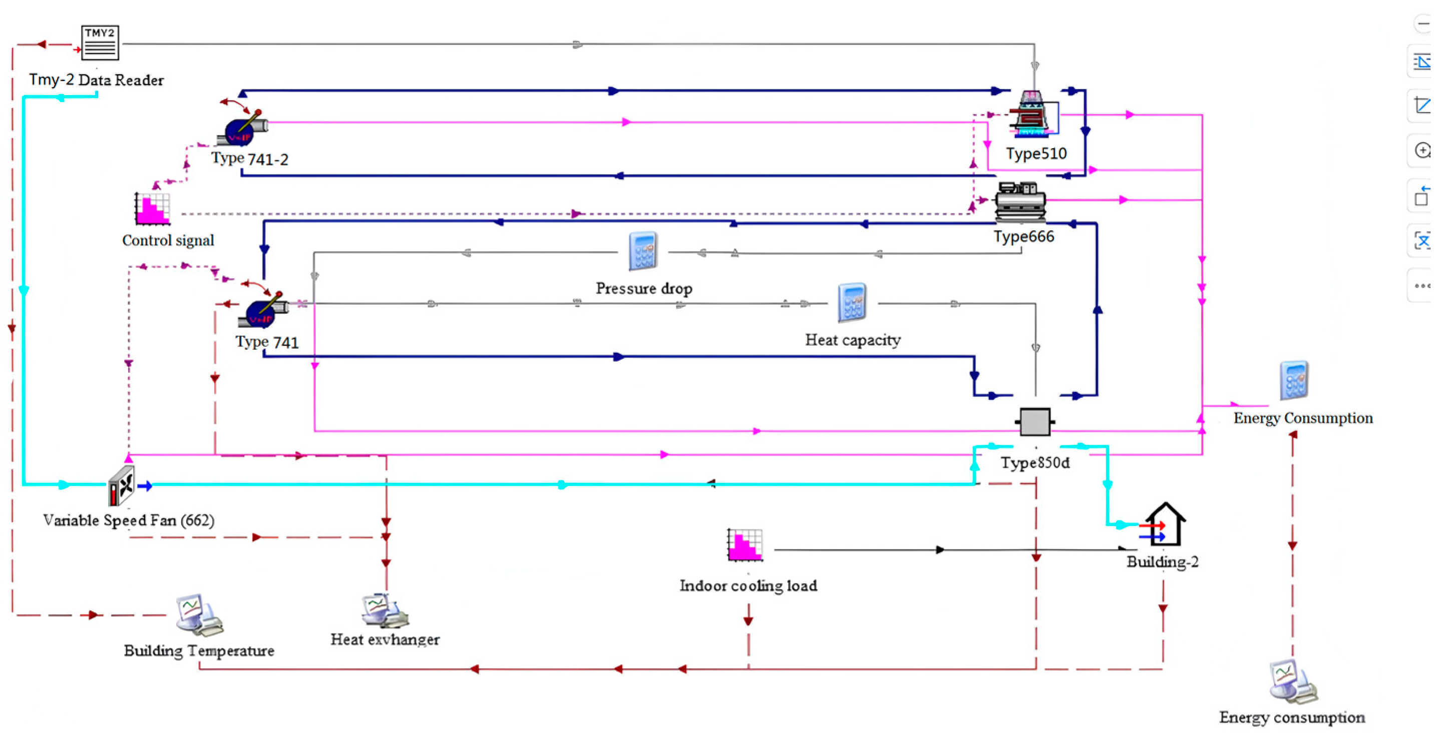
The entirety of the cooling load was covered by a central air conditioning system. The central air conditioning system was switched on from 06:00 to 18:00 in the summer months (June to August). The complete TRNSYS system model is shown graphically in
Figure 5.
The developed custom Type 850d component was used to describe the fan coil units, and the following generic types were used for all other components:
Building: energy rate control building (Type690);
Chiller: a vapor compression-style water-cooled chiller (Type666);
The data files were constructed from the performance data for the ElectricEIRChiller Carrier 19XR 742kW/5.42COP/VSD;
Cooling Tower: closed-circuit cooling tower (Type 510);
Fan: variable speed fan (Type 662);
Pump: variable speed pump (Type741);
Other component model: weather data processor; main equation block.
3.3. Simulation Setup
Two separate cases were simulated in this study. Case 1, as the control group, simulated a conventional air conditioning system with water as a cooling medium. In Case 2, the structure of the system was kept the same as in Case 1, but the phase change material emulsion PCE-10 was used as the cooling medium instead of water.
With the aim of approaching reality, the designs of the two air conditioning systems were based on the guidelines in the Practical Heating and Air Conditioning System Design Manual [
25].
Determination of cooling load: The design cooling load is 2000 W.
Determination of air flow rate: In the office building, the room area requirement is 4 m2/person, and a minimum of 30 m3/h/person of air supply is required. In a 4.5 × 3.6 m office room, the number of occupants is four persons, and it will need 120 m3/h (154.8 kg/h) of fresh air.
Determining the number of air handling units: The technical data of the self-assembled air handling unit were used for this study. The number of fan coil units is related to the cooling load and cooling capacity of fan coil units at a medium level. Thus, the number of fan coil units required is as follows:
Therefore, two air handling units can supply 690 kg/h of fresh air in total, which meets the required fresh air supply without the need for an additional ventilation system.
Determining the size of other primary equipment: Based on the cooling load and number of fan coil units, the following primary equipment was selected accordingly. The technical data are listed in
Table 5.
4. Results and Discussion
4.1. Cooling Performance
The performances of two air handling units have been simulated based on weather data for 31 July (the hottest day).
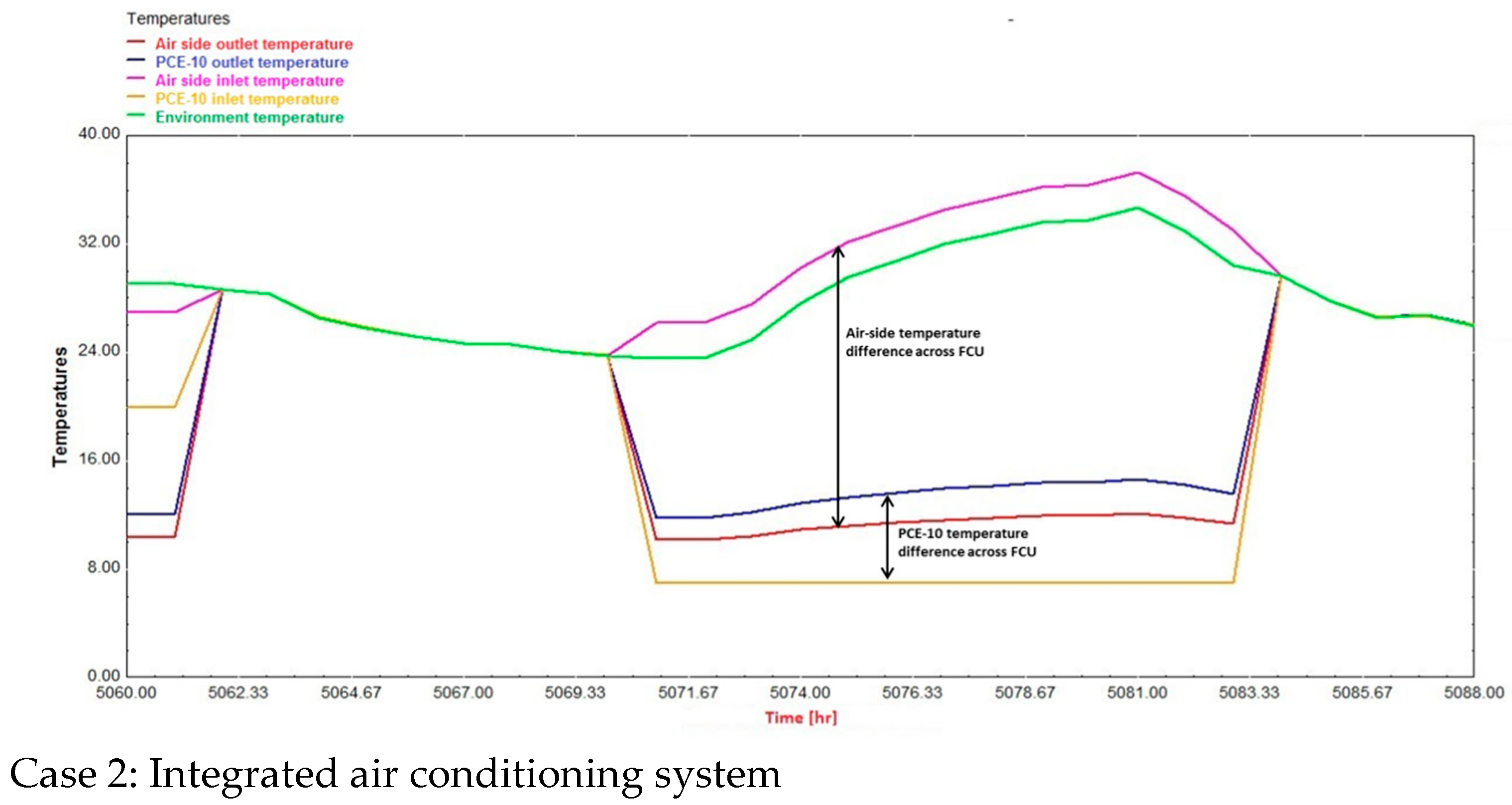
Figure 6 shows the performances of Case 1 and Case 2. The air conditioning system started working at 6am (5070 h). The performances of the two systems were fairly similar. The temperatures of the inlet air and fluid increased by 2 °C and 0.2 °C before entering the FCUs due to rejected heat from the fan and pump. Fluid-side temperatures increased by roughly 4.8 °C and 5.1 °C in Case 2 and Case 1, respectively. The air was effectively cooled from 30 °C to 13.6 °C and 13.8 °C for Case 2 and Case 1, respectively. It was noticed that the two systems achieved similar cooling performances, yet the average effectiveness of the phase change emulsion-integrated air conditioning system (0.83) was slightly lower than that of the normal air conditioning system (0.87), probably because of the variation of the PCME’s heat capacity. During peak load hours, the outlet temperature of the PCME was around 13.5 °C, at which temperature the heat capacity dropped to 3.8 kJ/kgK and the effectiveness changed to approximately 0.91.
The performances of two complete systems are presented in the form of a comparison between an office room equipped with a chilled water system (Case 1) and another with a chilled PCE-10 air conditioning system (Case 2).
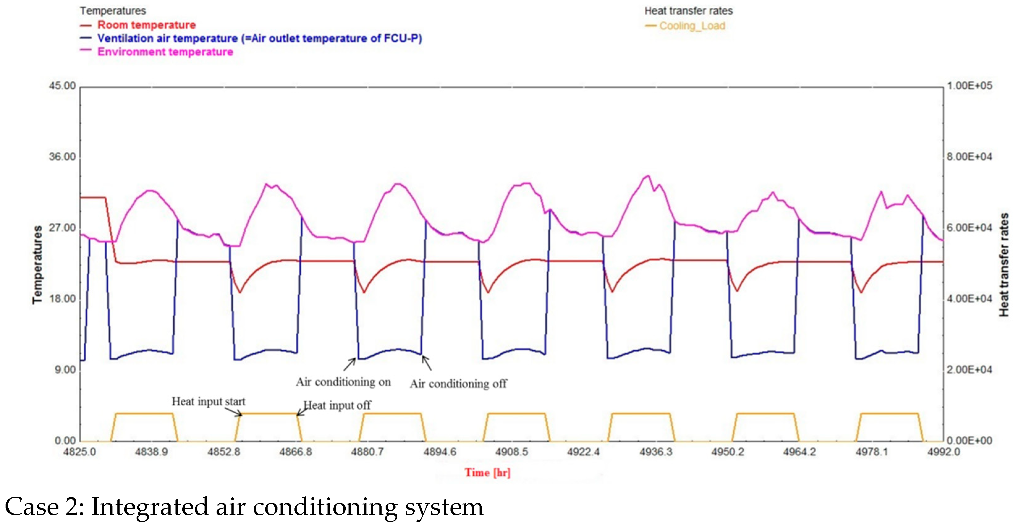
The comparisons of the hourly indoor air temperatures of Case 1 and Case 2 are presented in
Figure 7 for the hottest week (20–26 July). In both cases, the room temperature did not vary significantly with the outdoor temperature. As the air conditioning system started working 1 h earlier than the other equipment, the room temperature dropped to 18 °C. Then, it gradually rose to 20 °C due to heat input from the office equipment. At night, when the air conditioning system was off, the heat capacitance inside the office released heat and kept the temperature at 21 °C.
In Case 1, 608 kg/h of chilled water was used to keep the room temperature at 20 °C during the daytime when the air conditioning system was operating. In Case 2, it only took 260 kg/h to achieve the same cooling effect.
4.2. Energy Consumption
The energy consumption of Case 1 and Case 2 for the summer months (June to August) is broken down in
Figure 8. Case 1 consumed 4036 MWh of energy during its 3-month operation, among which 53% of energy was consumed by the chiller, followed by 26% by the refrigerant distribution system (i.e., pumps). Chilled water pump power alone was responsible for 6.5% of the total energy usage. In Case 2, the total energy consumption was 3751 MWh, which is a reduction of 7%, and the energy used by the chilled water pump was reduced significantly by roughly 50%.
5. Conclusions
In this paper, the idea of applying a phase change emulsion into an air conditioning system as a cooling medium was explored, and the performance of a phase change emulsion in an air conditioning system was evaluated with the transient system simulation program TRNSYS.
As the current TRNSYS components failed to model the performance of phase change emulsion in cooling coils, a new component was therefore developed. This custom component uses the effectiveness-NTU method to model the heat exchanger and the effective heat capacity method to incorporate this into the heat exchanger model by using a force function. It has been validated that this component could model the cooling effect of fan coil units with a PCME. Fan coil units with a PCME have a rated cooling capacity of 1.6 kW and a rated air flow rate of 516 kg/h. Compared with a normal FCU, it was found that fan coil units with a PCME could cut the amount of cooling media by 50% but still achieve the same cooling capacity.
By incorporating the technical data of an integrated PCME/fan coil unit into the TRNSYS system, the annual energy consumption of the integrated PCME/air conditioning system and the normal air conditioning system were analyzed based on a model room located in Ningbo, China. The simulation results showed that the PCME/air conditioning system could achieve the same cooling effect as the normal chilled water system with 50% less cooling media and a 7% reduction in the energy consumed by the air conditioning system. However, this study only focused on one field condition. For future studies, simulations and experiments using other field conditions and economic assessments should be carried out to assess the feasibility of a PCME/air conditioning system. In addition, the mass-averaged heat capacity used assumes thermal equilibrium at all times; therefore, other methods to better simulate the thermal delay are suggested.
Author Contributions
Conceptualization, J.D.; methodology, G.K. and J.S.; software, J.S.; validation, J.S.; writing—review and editing, Y.W. and J.S. All authors have read and agreed to the published version of the manuscript.
Funding
This research received no external funding.
Data Availability Statement
The data used to support the findings of this study are included in this study and also available from the corresponding author upon request.
Conflicts of Interest
The authors declare no conflicts of interest.
Abbreviations
The following abbreviations are used in this manuscript:
| QFCU | Cooling capacity of the fan coil unit, W |
| QW | Cooling capacity of the water side, W |
| Qair | Cooling capacity of the water side, W |
| Cc | Heat capacity rate of the cold side, kJ/(g·K |
| Ch | Heat capacity rate of the hot side, kJ/(g·K) |
| Cpc | Specific heat of the cold side, kJ/(kg·K) |
| Cph | Specific heat of the hot side, kJ/(kg·K) |
| Cp,PCM | Specific heat of paraffin in the solid state, kJ/(g·K) |
| Cp,W | Specific heat of water, kJ/(kg·K) |
| Cpm,eff | Effective specific heat of the PCME, kJ/(kg·K) |
| mc | Mass flow rate of the cold side, kg/s |
| mh | Mass flow rate of the hot side, kg/s |
| U | Overall heat transfer coefficient, W/(m2·K) |
| A | Heat transfer area, m2 |
| ε | Effectiveness |
| Cmax | Maximum value of Ch and CC |
| Cmin | Minimum value of Ch and CC |
| T | Temperature, °C |
| Th,o | Hot-side outlet temperature, °C |
| Th,i | Hot-side inlet temperature, °C |
| Tc,o | Cold-side outlet temperature, °C |
| Tc,i | Cold-side inlet temperature, °C |
| Qtotal | Total heat transferred, W |
| Qmax | Maximum amount of heat transferred, W |
| Δh | Latent heat of fusion, kJ/kg |
| TMPL | Onset melting temperature, °C |
| TMPH | End-phase change temperature, °C |
| XPCM | Weight fraction of the PCM, % |
| PCM | Phase change material |
| FCU | Fan coil unit |
| PCME | Phase change emulsion |
References
- Zhong, W. Building Air Conditioning Energy Consumption and Energy Saving Measures in China. Master’s Thesis, Environment Engineering, MSc Chongqing University, Chongqing, China, 2004. [Google Scholar]
- Bhatia, A. Centralized vs. Decentralized Air Conditioning Systems; Presented at the Course No: M05-012; Continuing Education and Development, Inc.: New York, NY, USA, 2011. [Google Scholar]
- CIBSE. CIBSE Guide B: Heating, Ventilating, Air Conditioning and Refrigeration; The Chartered Institution of Building Services Engineers: London, UK, 2005. [Google Scholar]
- Shao, J.; Darkwa, J.; Kokogiannakis, G. Review of phase change emulsions (PCMEs) and their applications in HVAC systems. Energy Build. 2015, 94, 200–217. [Google Scholar] [CrossRef]
- Youssef, Z.; Delahaye, A.; Huang, L.; Trinquet, F.; Fournaison, L.; Pollerberg, C.; Doetsch, C. State of the art on phase change material slurries. Energy Conv. Manag. 2013, 65, 120–132. [Google Scholar]
- Delgado, M.; Lázaro, A.; Mazo, J.; Zalba, B. Review on phase change material emulsions and microencapsulated phase change material slurries: Materials, heat transfer studies and applications. Renew. Sustain. Energy Rev. 2012, 16, 253–273. [Google Scholar] [CrossRef]
- Chen, B.; Wang, X.; Zhang, Y.; Xu, H.; Yang, R. Experimental research on laminar flow performance of phase change emulsion. Appl. Therm. Eng. 2006, 26, 1238–1245. [Google Scholar] [CrossRef]
- Li, Q.; Zheng, C.; Shirazi, A.; Mousa, O.B.; Moscia, F.; Scott, J.A.; Taylor, R.A. Design and analysis of a medium-temperature, concentrated solar thermal collector for airconditioning applications. Appl. Energy 2017, 190, 1159–1173. [Google Scholar] [CrossRef]
- Bouzenada, S.; McNevin, C.; Harrison, S.; Kaabi, A. Performance of a liquid desiccant air-conditioner driven by evacuated-tube, flat-plate, or hybrid solar thermal arrays. Energy Build. 2016, 117, 53–62. [Google Scholar] [CrossRef]
- Wang, M.; Hu, E.; Chen, L. Simulation of a radiation-enhanced thermal diode tank (RTDT) assisted refrigeration and air-conditioning (RAC) system using TRNSYS. J. Build. Eng. 2024, 82, 108168. [Google Scholar] [CrossRef]
- Kanan, S.; Dewsbury, J.; Lane-Serff, G.F.; Asim, M. The effect of ground conditions under a solar pond on the performance of a solar air-conditioning system. Energy Procedia 2016, 91, 777–784. [Google Scholar] [CrossRef]
- Abbassi, Y.; Baniasadi, E.; Ahmadiki, H. Transient energy storage in phase change materials, development and simulation of a new TRNSYS component. J. Build. Eng. 2022, 50, 104188. [Google Scholar] [CrossRef]
- Allouche, Y.; Varga, S.; Bouden, C.; Oliveira, A. A Trnsys simulation of a solar-driven ejector air conditioning system with an integrated PCM cold storage. In Proceedings of the International Conference on Technologies & Materials for Renewable Energy, Rangpo, India, 8–10 December 2017; AIP Publishing LLC: New York, UY, USA, 2017. [Google Scholar]
- Feng, G.; Liu, M.; Huang, K.; Qiang, X.; Chang, Q. Development of a math module of shell and tube phase-change energy storage system used in TRNSYS. Energy 2019, 183, 428–436. [Google Scholar] [CrossRef]
- Cengel, Y.A.; Boles, M.A. Thermodynamics: An Engineering Approach; 8. edition in SI units ed; McGraw-Hill Education: New York, NY, USA, 2015. [Google Scholar]
- Alisetti, E. Forced Convection Heat Transfer to Phase Change Material Slurries in Circular Ducts. Ph.D. Thesis, University of Miami, Coral Gables, FL, USA, 1998. [Google Scholar]
- Roy, S.K.; Avanic, B.L. Laminar forced convection heat transfer with phase change material suspensions. Int. Commun. Heat Mass. Transf. 2001, 28, 895–904. [Google Scholar] [CrossRef]
- Roy, S.K.; AVvanic, B.L. Turbulent heat transfer with phase change material suspensions. Int. J. Heat Mass. Transf. 2001, 44, 2277–2285. [Google Scholar] [CrossRef]
- Alisetti, E.; Roy, S.K. Forced convection heat transfer to phase change material slurries in circular ducts. Int. J. Thermophys. 2000, 14, 115–118. [Google Scholar] [CrossRef]
- Chen, K.; Chen, M.M. An analytical and experimental investigation of the convective heat transfer of phase change material suspension flow. In Proceedings of the International Symposium on Multiphase Flow (ii), Okinawa, Japan, May 1987; Volume 2, pp. 496–501. [Google Scholar]
- Shao, J.; Darkwa, J.; Kokogiannakis, G. Development of a novel phase change material emulsion for cooling systems. Renew. Energy 2016, 87, 509–516. [Google Scholar] [CrossRef]
- China Meteorological Bureau; Climate Information Center Climate Data Office; Tsinghua University. China Standard. In Weather Data for Analyzing Building Thermal Conditions; China Building Industry Publishing House: Beijing, China, 2005. [Google Scholar]
- The Architectural Design and Research Institute of Zhejiang University. Design Standard for Energy Efficiency of Public Buildings in the Zhejiang Province; China Planning Press: Beijing, China, 2018. [Google Scholar]
- Lu, Y. Practical Heating and Air Conditioning System, 2nd ed.; China Architecture & Building Press: Beijing, China, 2007. [Google Scholar]
- Lu, Y. Design Manual for Domestic Heating Cooling and Air Conditioning; China Building Industry Press: Beijing, China, 2007. [Google Scholar]
| Disclaimer/Publisher’s Note: The statements, opinions and data contained in all publications are solely those of the individual author(s) and contributor(s) and not of MDPI and/or the editor(s). MDPI and/or the editor(s) disclaim responsibility for any injury to people or property resulting from any ideas, methods, instructions or products referred to in the content. |
© 2025 by the authors. Licensee MDPI, Basel, Switzerland. This article is an open access article distributed under the terms and conditions of the Creative Commons Attribution (CC BY) license (https://creativecommons.org/licenses/by/4.0/).


