Article

Numerical Simulation-Based Study on Influence of Different Connection Configurations of Viscous Dampers on Seismic Performance

1
CCCC Second Highway Engineering Co., Ltd., Xi’an 710065, China
2
College of Civil Engineering and Architecture, Xinjiang University, Urumqi 830046, China
3
Xinjiang Key Laboratory of Building Structure and Earthquake Resistance, Xinjiang University, Urumqi 830046, China
*
Author to whom correspondence should be addressed.
Buildings 2025, 15(11), 1827; https://doi.org/10.3390/buildings15111827
Submission received: 21 April 2025 / Revised: 8 May 2025 / Accepted: 21 May 2025 / Published: 26 May 2025
(This article belongs to the Section Building Structures)

Abstract

To investigate the influence of different connection configurations of viscous dampers on seismic mitigation performance, this study conducts a numerical simulation analysis of a 10-story inpatient building in Bazhou People’s Hospital, comparing the energy dissipation efficacy of viscous dampers under three connection types: diagonal bracing, chevron bracing, and wall-mounted connections. The results demonstrate that both chevron and wall-mounted configurations exhibit superior seismic mitigation performance compared to diagonal bracing. Specifically, chevron bracing is more suitable for mid- to high-rise structures, while wall-mounted connections achieve marginally better performance in low-rise buildings. However, the latter’s efficacy diminishes in mid- to high-rise structures due to the influence of wall self-weight. This study provides practical insights for optimizing the arrangement and application of viscous dampers in engineering projects.

1. Introduction

With accelerating urbanization and increasingly complex building structures, concerns regarding structural dynamic responses and safety under seismic loads have intensified. As stipulated in China’s Classification Standard for Seismic Fortification of Buildings, critical medical facilities in tertiary hospitals—including outpatient, diagnostic, and inpatient units—are classified as special fortification structures, while similar facilities in secondary and tertiary hospitals are designated as priority fortification structures [1,2,3]. Traditional seismic design relies on structural strength and ductility for energy dissipation, yet such approaches risk severe damage or collapse under intense seismic events, failing to meet safety requirements for hospital buildings. Consequently, supplemental damping devices that dissipate seismic energy have emerged as a key strategy for enhancing structural resilience. Among these, viscous dampers are widely adopted in engineering practice due to their high energy dissipation capacity, minimal impact on structural stiffness, and stable force transmission. However, the connection configuration of viscous dampers critically influences their energy dissipation efficiency and overall seismic mitigation performance, necessitating further research into optimal placement strategies. This study evaluates the seismic mitigation efficacy of different connection configurations, particularly brace-type and wall-mounted systems, through a case study of a 10-story frame structure at Bazhou People’s Hospital in Korla City.
Recent research has extensively explored the seismic mitigation mechanisms, connection configurations, and engineering applications of viscous dampers. Michael C. Constantinou [4] compared diagonal, chevron, and toggle-brace connections, highlighting the superior energy dissipation of toggle-brace systems via geometric amplification effects, validated through engineering case studies. Abdalla Mahamad Affan Alhamdany [5] introduced energy dissipation techniques using viscous dampers in school buildings. Mohammed Samier Sebaq [6] investigated damage indices for viscous dampers under low-intensity earthquakes through experiments and simulations, though their findings were limited to steel structures and excluded complex systems like frame shear wall structures. Li Yi et al. [7] studied the influence of different damper connection modes on the seismic reduction performance of a teaching building through numerical simulation, with a particular focus on the working state of the lasso structure. Wang and Huang et al. [8] systematically and comprehensively investigated the seismic performance of a 14-story-frame shear wall structure under two different connection modes by organically combining multiple platforms, such as ETABS, adopting the response spectrum method, the elastic time–history analysis method, and the elastoplastic time–history analysis method. Hua Chenglong et al. [9] studied the relationship between different connection modes and damping coefficients by studying the mechanical properties of different connection modes of viscous dampers in a steel frame model. Xu Xiao et al. [10] conducted numerical simulations to study the influence of different connection modes on the seismic performance of reinforced concrete frame structures and carried out time–history analysis under rare earthquakes. Zhu Lin et al. [11] proposed an objective function to compare the advantages and disadvantages of structural seismic performance under different connection modes and derived the optimal layout mode. Yang Xiaofeng et al. [12] studied the frame structure of bottom-story buildings, adopted different types of damper layout modes, compared the displacement, inter-story displacement, and acceleration of the structure in two principal axis directions, and verified the seismic performance of energy-dissipating and shock-absorbing structures equipped with viscous dampers. Song Lixun et al. [13] studied the influence of different connection modes on the mechanical properties of long-span cable-stayed bridges through numerical analysis. Wang Runze et al. [14] investigated the influence of different connection modes on the seismic performance of steel structure frame factories using ETABS 22.0.0. Lu Mingkuan et al. [15] identified the optimal installation positions of dampers by comparing the layout modes of damper systems in super high-rise buildings. This paper systematically investigates the influence of different connection modes on the shock absorption performance based on the ETABS platform and a practical engineering model. Taking the maximum inter-story displacement and hysteretic curves of viscous dampers under different connection modes as the judgment basis, we can obtain the general rules between connection modes and seismic performance, providing more universal design bases for engineering practice.

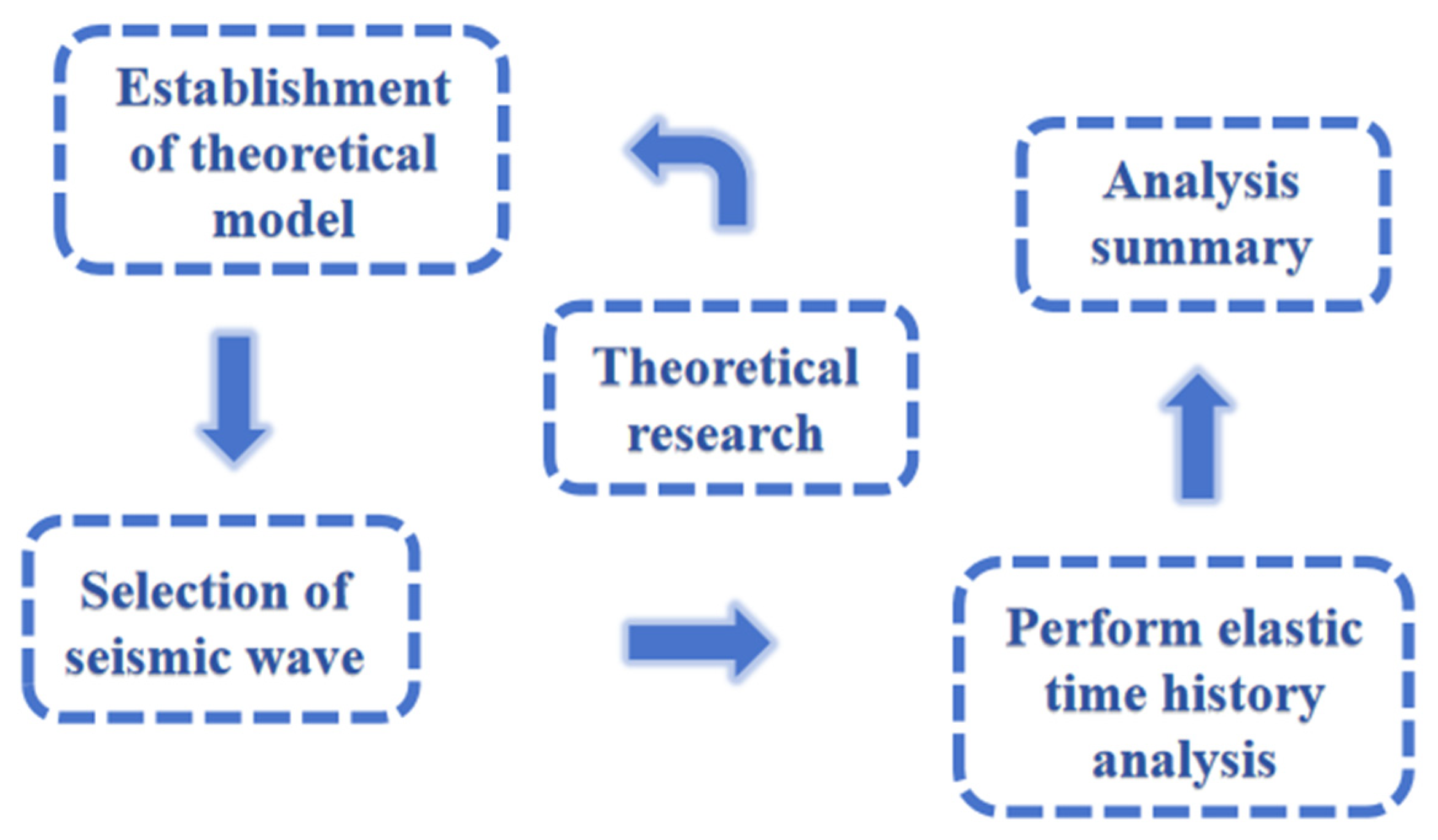
2. Research Methodology

Due to the complexity of seismic research and significant limitations imposed by physical experimental constraints, this study employs numerical simulation analysis using ETABS 22.0.0. Theoretical models are established within the platform to simulate the operational states of different viscous dampers during seismic events. The fast time–history analysis method is utilized to obtain response data for the building models, which are subsequently analyzed and synthesized to derive deeper insights or patterns. The specific research methodology is illustrated in Figure 1.

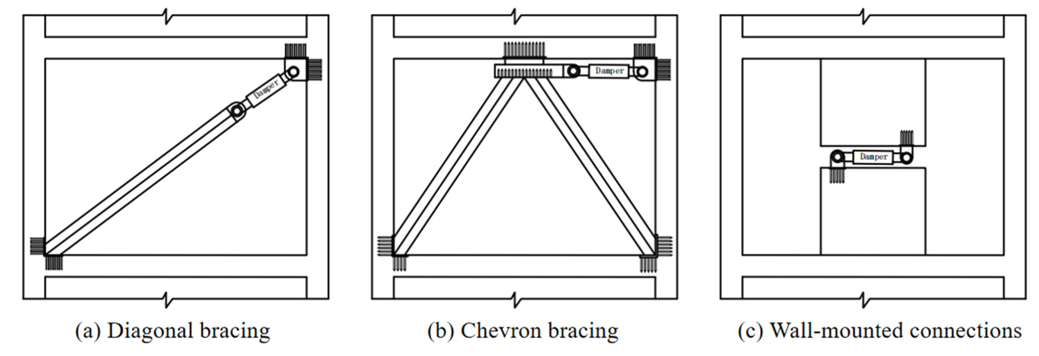
3. Working Mechanism of Viscous Damper Connection Configurations

Walls were used to form damper systems. Common configurations include inclined rod, herringbone, and wall-mounted connections. Under seismic loading, the lateral displacement of the structure induces inter-story shear deformation, driving relative motion at the ends of steel braces or between walls. This forces the damper to undergo compression or extension along its piston axis, generating diagonal or horizontal damping forces opposing structural displacement, thereby dissipating seismic energy.
The working mechanism is expressed as follows [4]:
u = f u F
Here, u = relative displacement at both ends of the damper; f = displacement amplification coefficient; and u F = inter-story displacement of the floor where the damper is installed.
For inclined rod connections (Figure 2a), the relative displacement between the two ends of the damper is less than the inter-story displacement of the floor where it is located;
For Chevron bracings (Figure 2b) and wall-mounted connections (Figure 2c), the relative displacement given by the two ends of the damper is equal to the inter-story displacement of the floor where it is located.

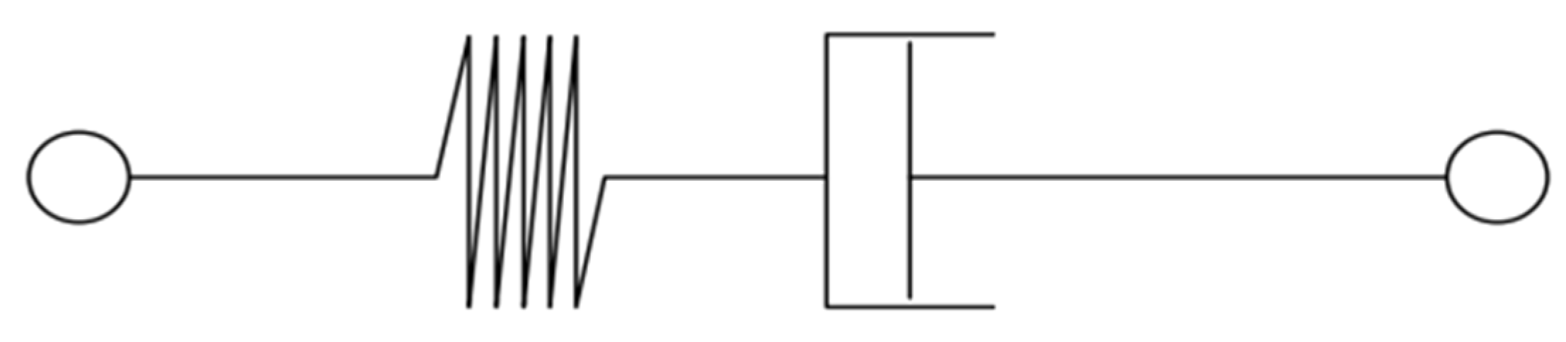
4. Seismic Mitigation Mechanism of Viscous Dampers

A viscous damper is a velocity-dependent energy dissipation device based on fluid dynamics principles. It exhibits negligible inherent stiffness, with damping forces solely proportional to velocity. The device demonstrates a well-defined elliptical hysteresis loop, and its mechanical behavior can be mathematically represented by a first-order Maxwell model [16]:
F d + λ F d = C 0 u
Here, F d = damping force; λ = relaxation time coefficient; C 0 = generalized damping coefficient; and u = relative velocity at both ends of the damper.
A comparison between experimental and theoretical values derived from the Maxwell model reveals that the λ F d term can be neglected when the frequency is below 4 Hz [17]. Since most engineering structures subjected to wind or seismic loads exhibit vibrations below 4 Hz (i.e., low-frequency vibrations), Equation (1) can be simplified as follows:
F d = C 0 u
Building on this, Taylor Devices Inc. optimized the mechanical model expression for viscous dampers. For horizontally installed viscous dampers, the following is used [18]:
F d = C 0 | u | α s i g n ( u )
For inclined installations, the following is used:
F d = C 0 | u | α s i g n ( u )
Here, θ = angle between the damper and the horizontal plane; C 0 = generalized damping coefficient; u = relative velocity at both ends of the damper; and α = velocity exponent, typically ranging from 0.3 to 1.0 in practical engineering.
When α = 1.0, the damper exhibits linear behavior. For α < 1.0, the damper becomes nonlinear, with damping force increasing rapidly at low velocities and decelerating as velocity rises.

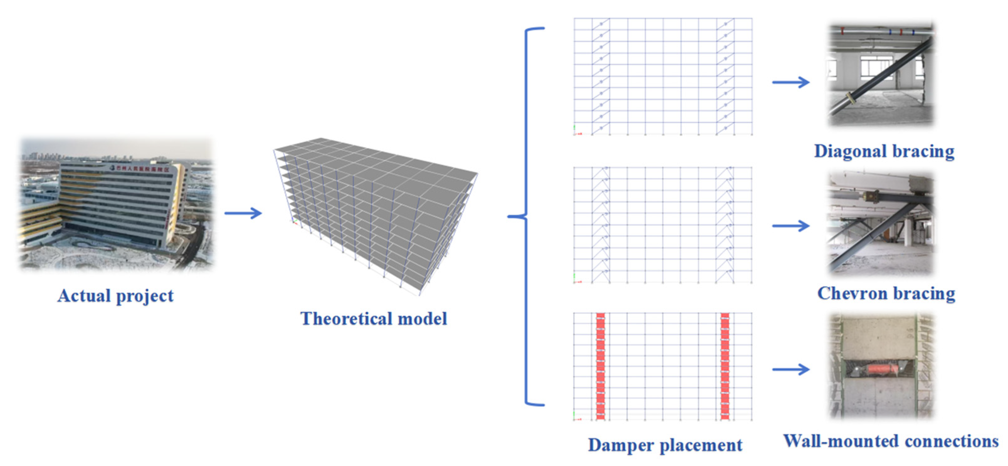
5. Engineering Case Study

5.1. Project Overview

This case study focuses on an inpatient building at Bazhou People’s Hospital in Korla City, the capital of Bazhou Prefecture. The structure comprises a 10-story reinforced concrete frame system with a total height of 43.8 m. The site is classified as having a seismic fortification intensity of 8 degrees (peak ground acceleration 0.2 g), belonging to design earthquake group II and site class II, with a characteristic period (Tg) of 0.40 s. The structure is categorized as a priority fortification facility (Class B). Seismic actions were calculated for an 8-degree intensity (0.2 g PGA), while seismic detailing adhered to 9-degree requirements. To systematically evaluate the influence of connection configurations on the seismic mitigation performance of viscous dampers, this case study employs elastic time–history analysis, focusing exclusively on the structural response along the X-direction under frequent earthquake levels. The maximum inter-story drift ratio is selected as the primary evaluation metric. The specific research process are shown in Figure 3.

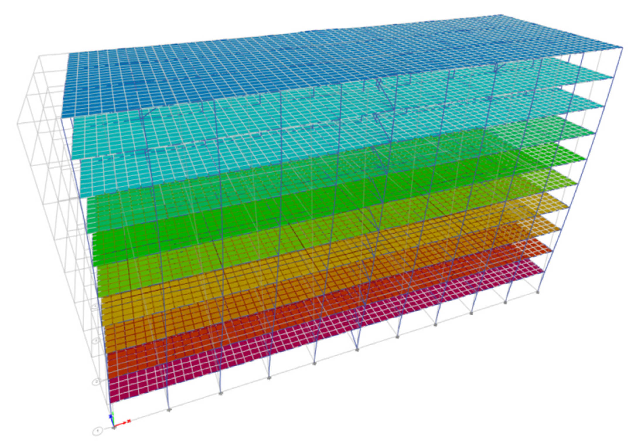
5.2. Model Development

Numerical simulations were conducted using structural elements native to the analysis software used. The key material parameters are summarized in Table 1. Permanent floor loads were set at 3.5 kN/m2, and live loads at 2.0 kN/m2, with fully fixed base supports applied. The viscous dampers are modeled using spring–damper elements based on the Maxwell model (the specific theoretical derivation of this model can be found in Section 4), a classical viscoelastic constitutive model designed to describe the mechanical behavior of materials exhibiting both elastic and viscous properties. This model is composed of a spring element and a damper element connected in series (See Figure 4 for the specific model), and it is widely used to simulate the dynamic responses of fluids, polymeric materials, and dampers in engineering structures. Notably, the stiffness of the dampers is neglected in the calculations. The arrangement positions and parameters of the dampers in the three connection configurations are identical, with the specific damper parameters as reported in Reference [19], as presented in Table 2.

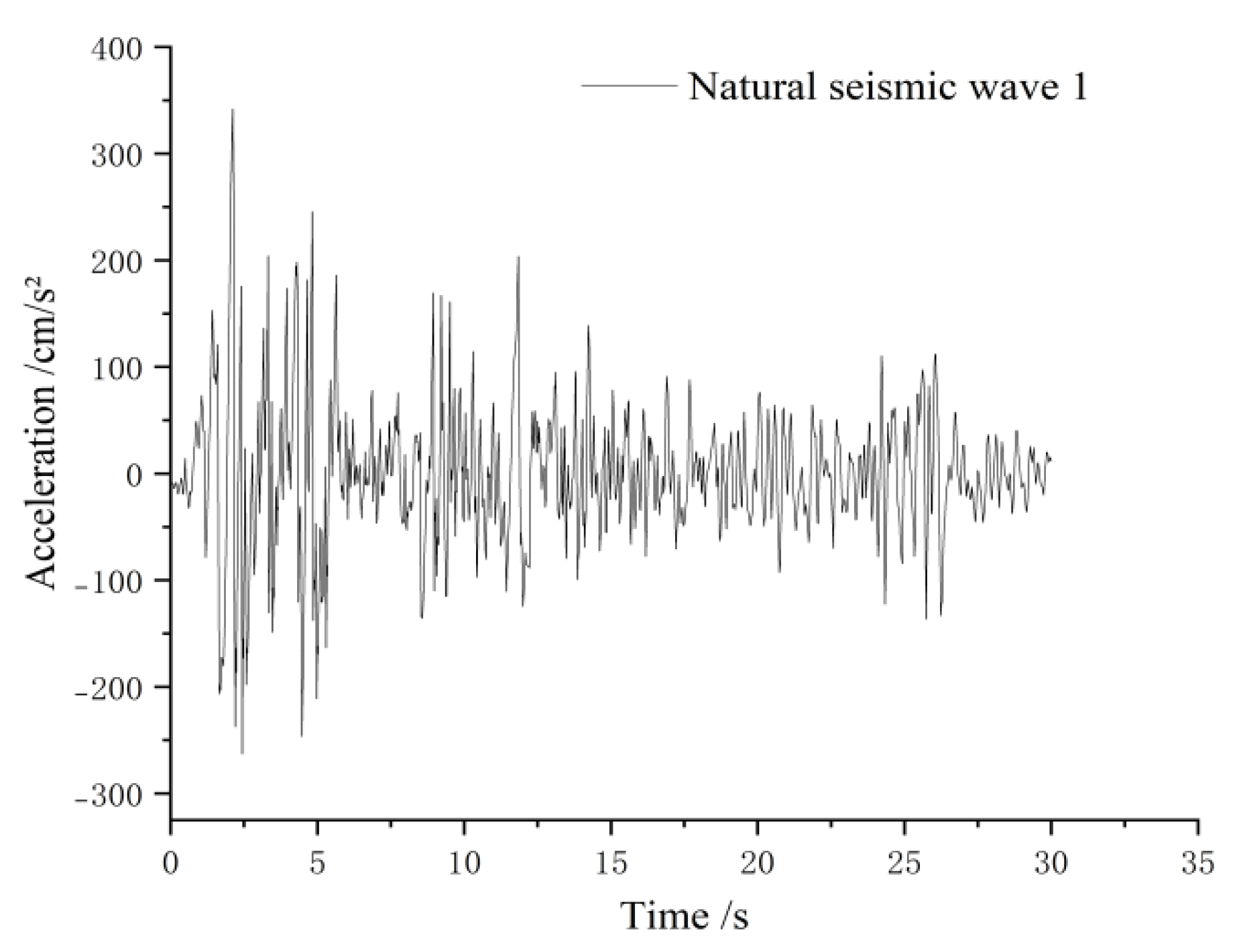
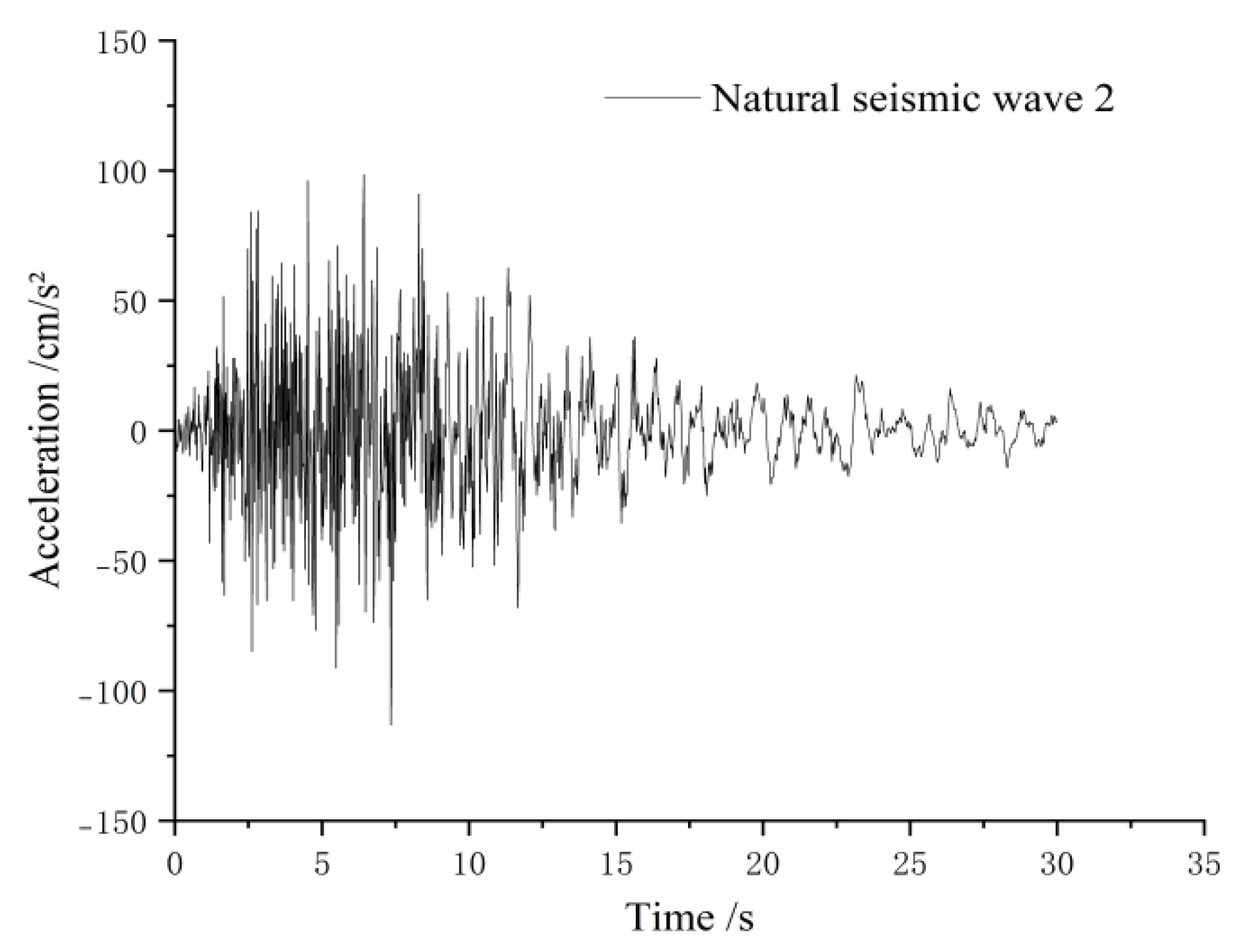
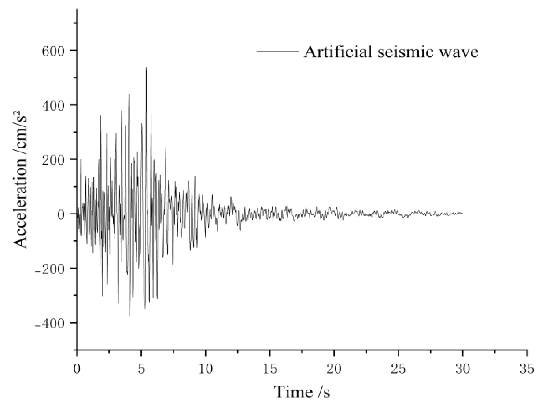
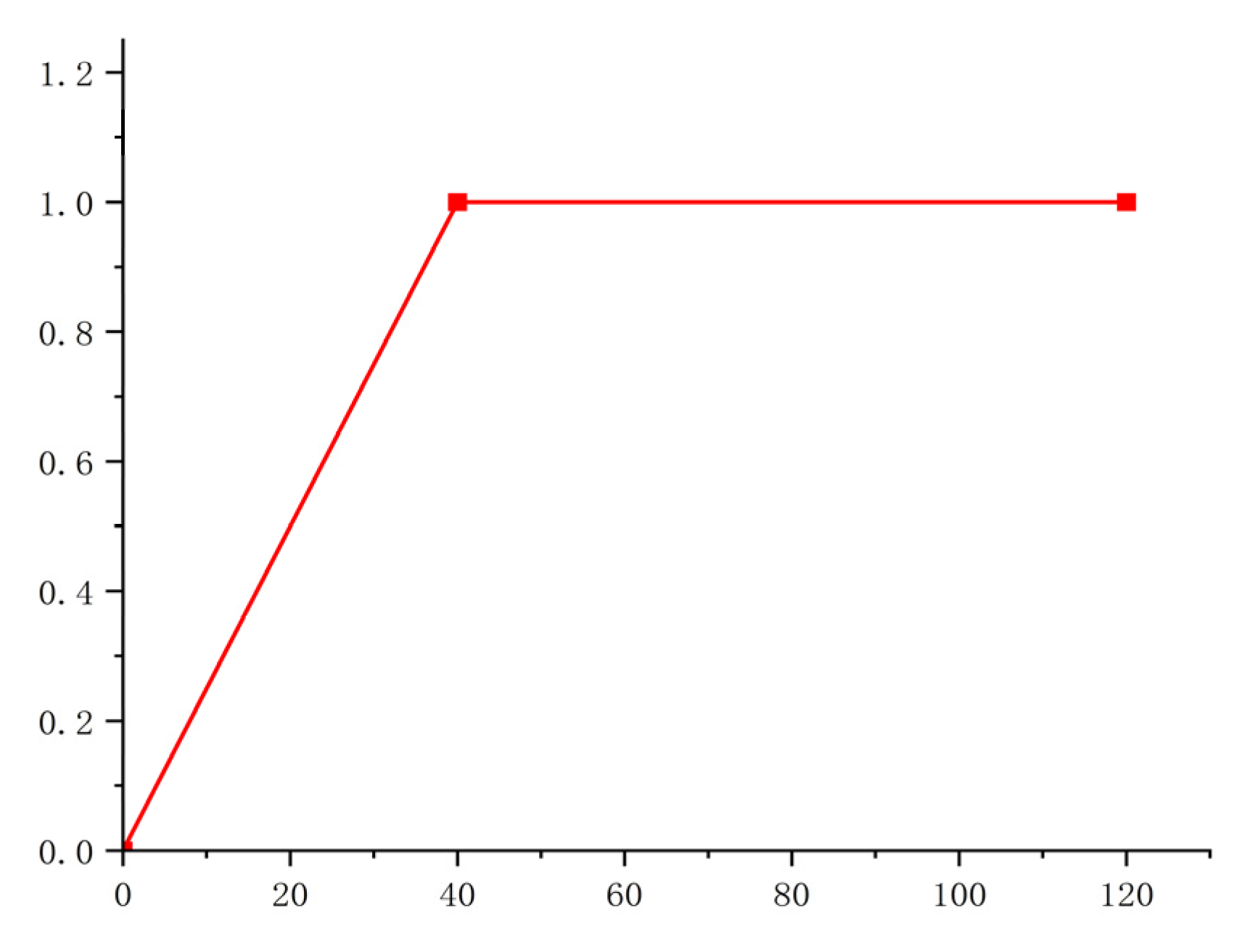
5.3. Selection of Seismic Waves

To ensure a rational investigation of the structural model, appropriate seismic waves must be selected as inputs for elastic time–history analysis. This study focuses on verifying and validating the seismic performance of designed or existing structures in practical engineering. To reduce computational effort while aligning with code-based design objectives, a seismic wave selection method grounded in the design response spectrum was adopted [20,21,22]. The selected seismic waves, comprising two natural waves and one artificial wave, were sourced from the National Seismic Network and the ETABS platform database. These waves were chosen in compliance with code requirements [23], considering engineering practicality and representativeness, to perform elastic time–history analysis under frequent earthquake conditions. The specific waveform is shown in Figure 5, Figure 6 and Figure 7.

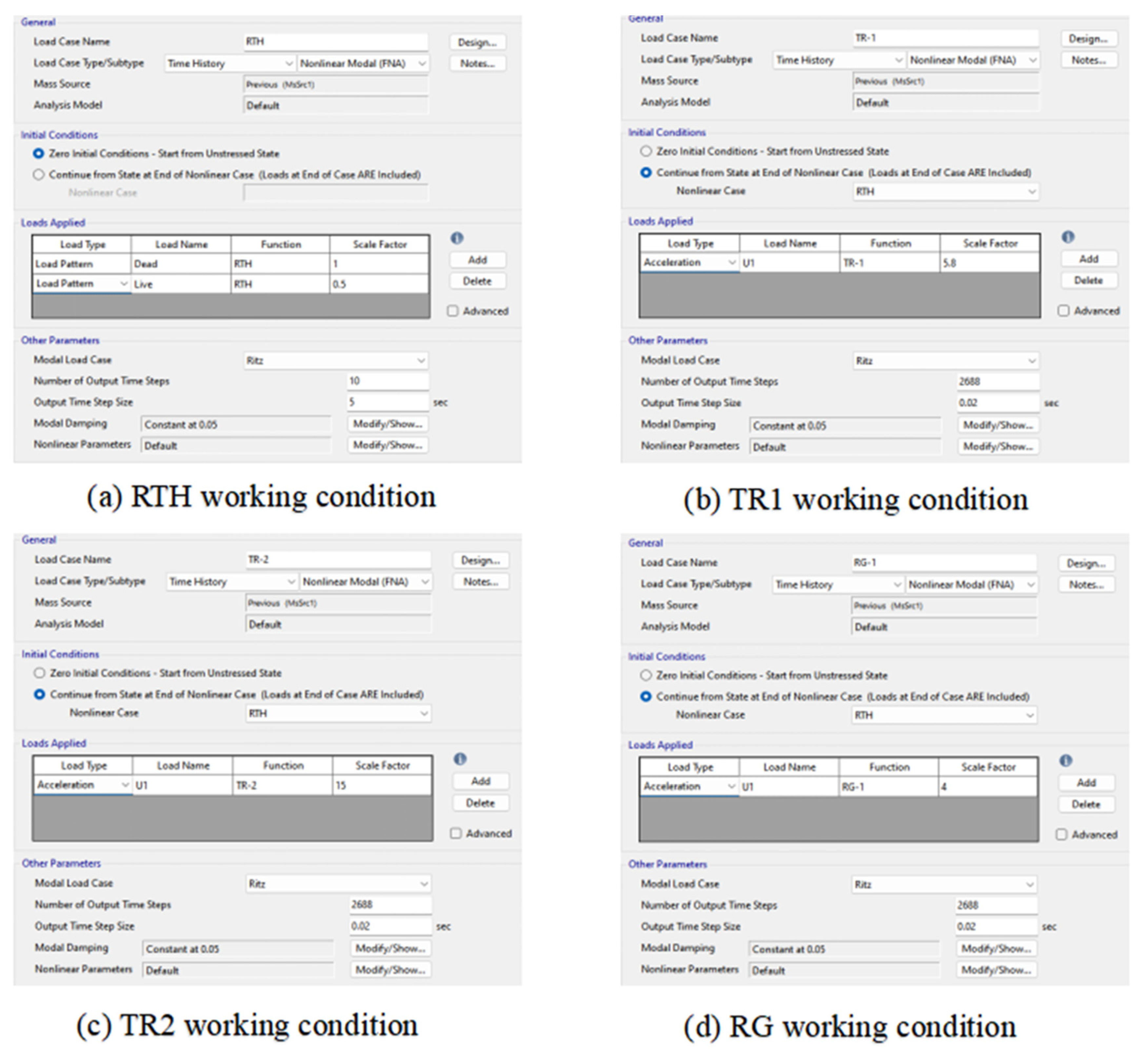
5.4. Elastic Time–History Analysis

After inputting the seismic time–history functions into the software, the load cases for elastic time–history analysis were defined. To balance research objectives and computational efficiency, the Ritz vector method [24] was employed for modal analysis due to its rapid iteration and computational convenience. The applied load types included acceleration and link loads, with the maximum number of modes determined as 60 through trial calculations to ensure that the cumulative modal participation mass reached at least 90% of the total structural mass.
To simplify the analysis and enhance computational speed, the Fast Nonlinear Analysis (FNA) method was utilized in defining the time–history module [25,26]. Four load cases—FNA-RTH, FNA-TR1, FNA-TR2, and FNA-RG—were established. The FNA-RTH case employed the slope function shown in Figure 8 as its time–history curve, serving as a precursor to simulate the force–displacement relationships and restore force characteristics of nonlinear connection elements. The remaining three seismic load cases were derived based on this precursor. During the definition of these seismic load cases, scaling coefficients were applied to adjust the amplitude of the seismic time–history functions [27], ensuring that the peak accelerations of the waves did not exceed the maximum limits specified for frequent earthquakes in the codes. Detailed parameter definitions are illustrated in Figure 9 and Figure 10.

6. Results Analysis

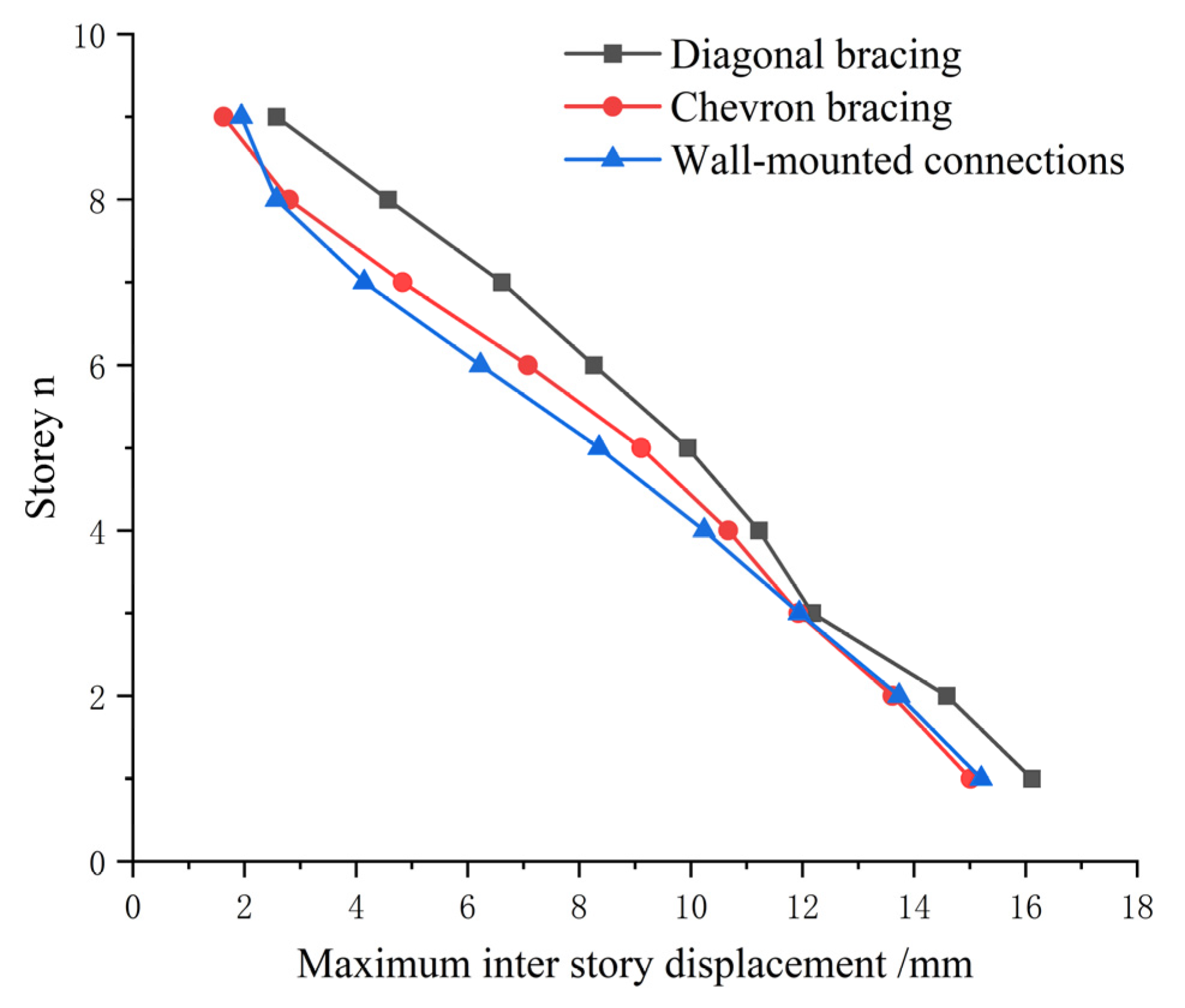
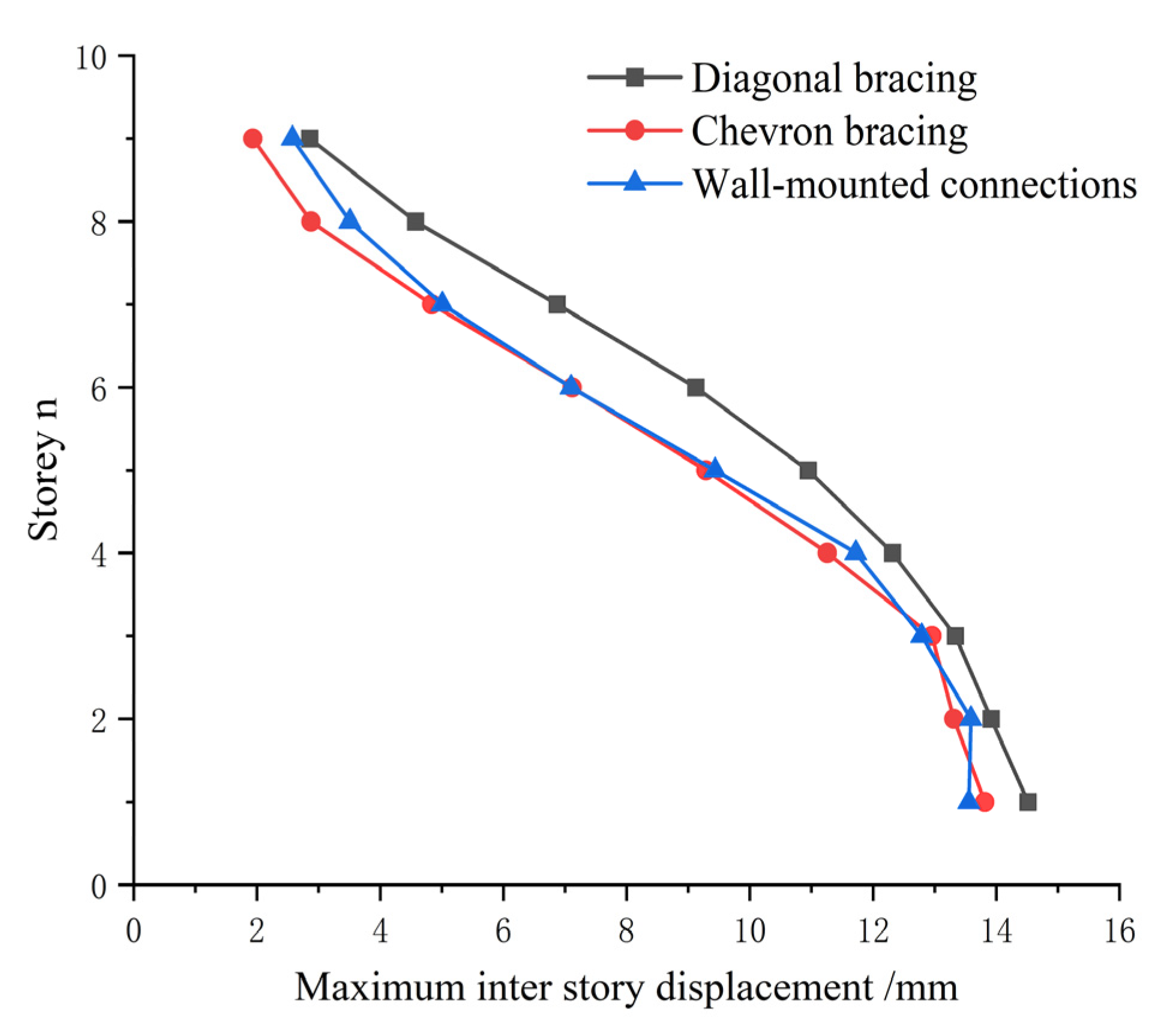
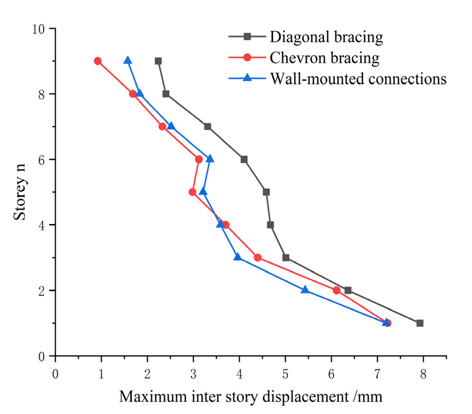
6.1. Maximum Inter-Story Drift

By comparing the analysis results and extracting the stress cloud diagram of the most typical building model (see Figure 11 for details), it can be concluded that the building model undergoes significant deformation under the action of seismic waves, and the viscous dampers undergo relative displacement, fully entering the working state. The stress state of the model shows a significant change with the change in floors, and the closer it is to the bottom, the greater the degree of deformation.
The damping analysis results for the maximum inter-story drifts of the building model are summarized in Table 3, Table 4 and Table 5 and Figure 12, Figure 13 and Figure 14. Under the TR1 wave (X direction), the controlled structure with diagonal brace connections exhibited the largest maximum inter-story drift, peaking at 16.114 mm. The wall-type connections ranked second with a peak drift of 15.204 mm, while the chevron connections showed the smallest peak drift of 15.013 mm. Under the TR2 wave (X-direction), the diagonal brace connections again yielded the largest maximum drift (14.517 mm), followed by chevron connections (13.815 mm), and wall-type connections (13.555 mm). For the RG wave (X-direction), diagonal brace connections remained the least effective, with a peak drift of 7.924 mm, followed by chevron connections (7.223 mm) and wall-type connections (7.194 mm).
Thus, under identical damping conditions, the maximum inter-story drifts of floors equipped with chevron and wall-type connections were consistently smaller than those with diagonal brace connections. This indicates that chevron and wall-type connections generally outperform diagonal brace connections in terms of seismic energy dissipation effectiveness. Analysis of the curve trends in the figures reveals that the maximum inter-story drift values and damping performance of chevron and wall-type connections vary across different floors and seismic load cases, demonstrating context-dependent advantages under the three earthquake scenarios.

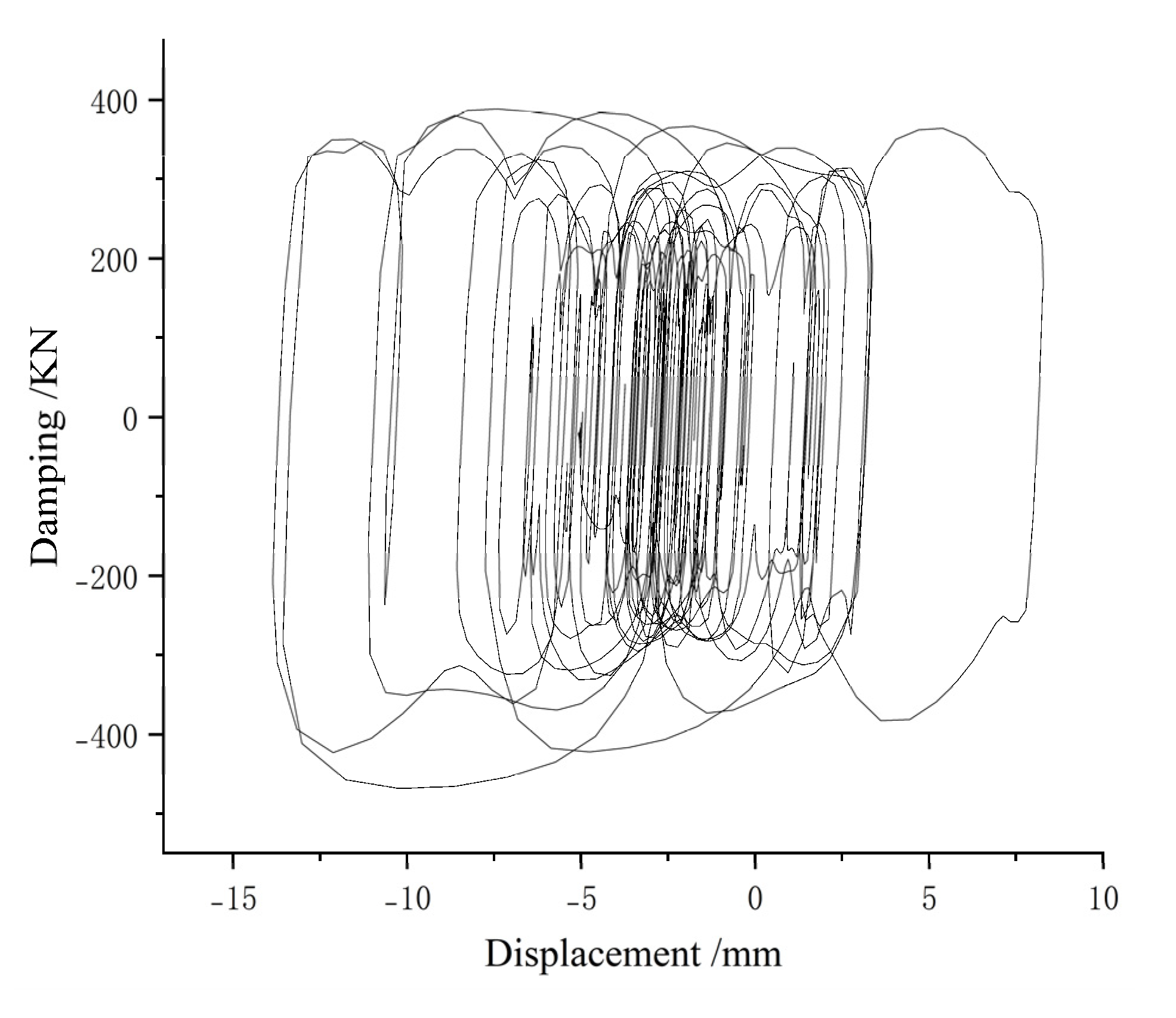
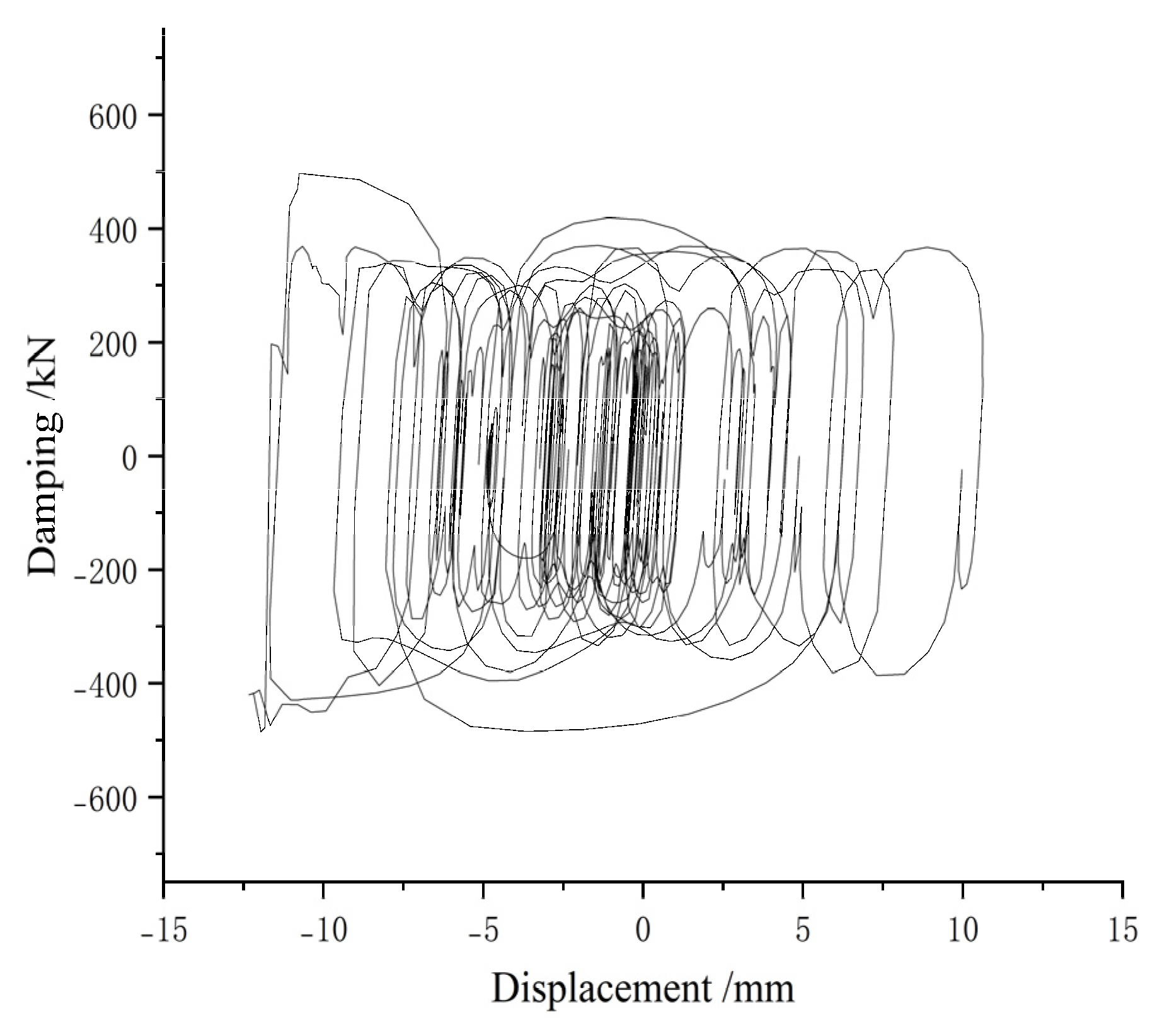
6.2. Energy Dissipation Characteristics of Viscous Dampers

During earthquakes, seismic energy is transferred through structural connections to viscous dampers, where it is absorbed and dissipated. This mechanism achieves the seismic design objectives of “economical performance under minor earthquakes, operational integrity under moderate earthquakes, and repairability under major earthquakes.” The energy dissipation mechanism of viscous dampers can be summarized through their energy distribution characteristics.
E T = E S + E C + E P + E D
Here, E T = total seismic input energy; E S = mechanical energy of structural vibration; E C = energy dissipated by structural damping; E P = energy dissipated by structural inelastic deformation; and E D = energy dissipated by viscous dampers.
To illustrate the energy dissipation efficacy of viscous dampers, hysteretic curves under different connection configurations were randomly selected. Figure 15, Figure 16 and Figure 17 show the hysteretic curves of viscous dampers in the X direction under seismic loading. These curves exhibit a typical velocity-dependent energy dissipation process, characterized by irregular elliptical shapes with full hysteresis loops. This indicates that the dampers effectively dissipate energy, significantly attenuating the total seismic input energy and achieving robust vibration mitigation.

7. Discussion

Numerical simulations reveal that, in practical engineering applications, both herringbone and wall-mounted connections demonstrate superior seismic mitigation performance compared to diagonal bracings. However, these two connection types exhibit distinct characteristics. The chevron bracing, installed between upper- and lower-frame beams and connected to columns via steel braces, offers lightweight construction and excellent energy dissipation. In contrast, the wall-mounted connections employ two concrete walls with embedded steel plates and anchor bolts between frame beams, with viscous dampers installed in the pre-reserved mid-wall space. While this method provides convenient installation and effective energy dissipation, the self-weight of concrete walls in mid- to high-rise buildings introduces additional structural loads, adversely affecting seismic resistance.
A comparative analysis of the maximum inter-story drift values across different floors (Table 6, Figure 18 and Figure 19) shows that for low-rise structures, wall-mounted connections yield slightly smaller drift values than chevron bracings, indicating marginally better performance. However, in mid- to high-rise buildings, chevron bracings exhibit significantly smaller drift values than floor height increases. This trend highlights the diminishing effectiveness of wall-mounted connections due to self-weight impacts, whereas chevron bracings demonstrate enhanced adaptability and superior energy dissipation in taller structures.

8. Conclusions

A numerical simulation study on the seismic mitigation performance of viscous dampers in a hospital building in Bazhou was conducted, analyzing three connection types: inclined rod, herringbone, and wall-mounted connections. The key conclusions are as follows:
(1)
Under identical seismic mitigation conditions, for frame structures similar to the hospital structure, both the herringbone and wall-mounted connections exhibit superior seismic reduction performance compared to the diagonal bracings. This is evidenced by the fact that under different seismic loads, the maximum inter-story drifts of structures employing herringbone and wall-mounted connections are consistently smaller than those using diagonal bracing connections.
(2)
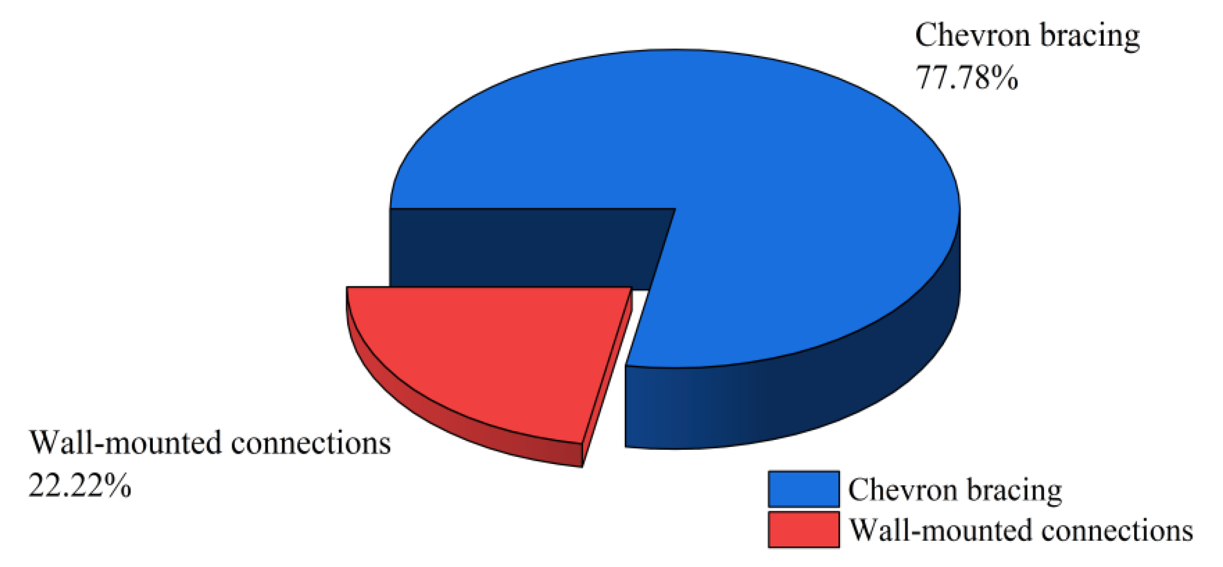
In terms of the applicability of connection types, the chevron bracings are suitable for medium-to-high-rise frame structures similar to the hospital structure, where its seismic reduction effect is more pronounced. While the wall-mounted connections demonstrate slightly better seismic performance than the chevron connection in low-rise frame structures of a similar type, their effectiveness is diminished in medium- to high-rise frame structures due to the influence of wall self-weight, resulting in less optimal seismic reduction compared to chevron bracings.
(3)
Energy Dissipation Mechanism: Viscous dampers effectively dissipate seismic energy, as evidenced by their velocity-dependent hysteretic curves. The hysteretic curves confirm robust energy absorption, validating their role in seismic mitigation.
In engineering practice, the selection of viscous damper connection types should consider building height and structural characteristics to optimize seismic performance. Numerical simulations reveal that, in practical engineering applications, both herringbone and wall-mounted connections demonstrate superior seismic mitigation performance.

Author Contributions

Conceptualization, X.Z. and A.J.; Methodology, A.J.; Validation, S.Z. and Q.L.; Formal analysis, X.Z.; Investigation, Q.L.; Resources, A.J.; Data curation, X.Z. and S.Z.; Writing—original draft, X.Z.; Writing—review & editing, A.J.; Visualization, S.Z.; Supervision, A.J.; Project administration, A.J.; Funding acquisition, A.J. All authors have read and agreed to the published version of the manuscript.

Funding

This work was supported by the National Natural Science Foundation of China (grant No. 52368051), the Natural Science Foundation of Xinjiang Uygur Autonomous (grant No. 2022D01C685) and the Research and Development of Key Construction Technologies for the Bazhou People’s Hospital Project Industry-University-Research Cooperation Agreement (grant No. 202409140034). The above-mentioned funders and their support are gratefully acknowledged.

Data Availability Statement

The original contributions presented in the study are included in the article, further inquiries can be directed to the corresponding author.

Conflicts of Interest

Author Xiaojian Zhang was employed by the company CCCC Second Highway Engineering Co., Ltd. The remaining authors declare that the research was conducted in the absence of any commercial or financial relationships that could be construed as a potential conflict of interest.

References

  1. GB 50223-1995; Classification standard for seismic fortification of buildings. Ministry of Construction of the People’s Republic of China: Beijing, China, 1995.
  2. GB 50223-2008; Classification Standard for Seismic Fortification of Building Engineering. SBTS: Louisville, KY, USA, 2008.
  3. GB 50223-2004; Standard for Classification of Seismic Fortification of Building Engineering (with article description). SBTS: Louisville, KY, USA, 2004.
  4. Constantinou, M.C.; Tsopelas, P.; Hammel, W.; Sigaher, A.N. Toggle-Brace-Damper Seismic Energy Dissipation Systems. J. Struct. Eng. 2001, 127, 105–112. [Google Scholar] [CrossRef]
  5. Alhamdany, A.M.A.; Dilsiz, A. Comparative evaluation of shear walls and fluid viscous dampers in seismic retrofitting of RC public school buildings. Structures 2025, 72, 108231. [Google Scholar] [CrossRef]
  6. Sebaq, M.S.; Xiao, Y.; Song, G. Damage indices of steel moment-resisting frames equipped with fluid viscous dampers. J. Asian Archit. Build. Eng. 2023, 22, 3496–3515. [Google Scholar] [CrossRef]
  7. Yi, L.; Haiwen, T.; Da, H. Research on seismic performance of viscous dampers with different connection modes. Eng. Seism. Resist. Reinf. 2008, 6, 60. [Google Scholar]
  8. Chengzhi, W.; Zhen, H.; Kangan, L. Energy dissipation and vibration reduction design using viscous dampers in a certain hospital. Archit. Struct. 2012, 201, 473–477. [Google Scholar]
  9. Chenglong, H. Study on the Similarity Relationship of Shaking Table Test of Steel Frame Model with Additional Viscous Damper; Xi’an University of Architecture and Technology: Xi’an, China, 2022. [Google Scholar]
  10. Xiao, X. Study on the Influence of Viscous Damper on Seismic Performance of Reinforced Concrete Frame Structure; Shandong Jianzhu University: Jinan, China, 2023. [Google Scholar]
  11. Zhu, L. Research on the Application of Viscous Damper in Energy Dissipation and Shock Absorption in Frame Structure; Xiamen University: Xiamen, China, 2020. [Google Scholar]
  12. Yang, X. Seismic Optimization Design of Low-Rise Buildings Based on Viscous Dampers; Dalian University of Technology: Dalian, China, 2015. [Google Scholar]
  13. Song, L. Research on Shock Absorption of Cable-Stayed Bridges Based on Viscous Dampers; Beijing Jiaotong University: Beijing, China, 2012. [Google Scholar]
  14. Wang, R. Design and Analysis of Shock Absorption Performance of Multi-Story Steel Structure Factory Buildings; North China University of Water Resources and Electric Power: Zhengzhou, China, 2023. [Google Scholar]
  15. Lu, M. Application of Boom Truss-Damper System in Wind Resistance and Vibration Reduction of Super High-Rise Buildings; Yanshan University: Qinhuangdao, China, 2023. [Google Scholar]
  16. Jia, B.; Luo, X.; Ding, J.; Zhang, Q. Research on seismic reduction effect of viscous dampers on space truss structures. Vib. Shock. 2014, 33, 124–130. [Google Scholar]
  17. Gattulli, V. Passive Energy Dissipation Systems in Structural Engineering T.T. Soong and G.F. Dargush John Wiley & Sons, Chichester. Meccanica 1999, 34, 65–66. [Google Scholar]
  18. Tiwari, P.; Badal, P.; Suwal, R. Effectiveness of fluid viscous dampers in the seismic performance enhancement of RC buildings. Asian J. Civ. Eng. 2023, 24, 309–318. [Google Scholar] [CrossRef]
  19. Gu, J.; Ma, Z.-D.; Hulbert, G.M. A new load-dependent Ritz vector method for structural dynamics analyses: Quasi-static Ritz vectors. Finite Elem. Anal. Des. 2000, 36, 261–278. [Google Scholar] [CrossRef]
  20. Ras, A. Far-field earthquake response examination of RC buildings equipped with fluid viscous dampers. Asian J. Civ. Eng. 2025, 26, 357–371. [Google Scholar] [CrossRef]
  21. Pu, Y.; Yingmin, L.; Ming, L. Selection control index of input seismic wave in structural time history analysis method. J. Civ. Eng. 2000, 33, 33–37. [Google Scholar]
  22. Zhe, Q.; Lieping, Y.; Peng, P. Comparative study on selection methods of ground motion records in elastoplastic time history analysis of building structures. J. Civ. Eng. 2011, 44, 10–21. [Google Scholar]
  23. GB 50011-2001; Code for Seismic Design of Buildings. SBTS: Louisville, KY, USA, 2001.
  24. Gong, Y.; Zhou, H.; Chen, P.; Yuan, M. Comparison of fast subspace iteration method, iterative Ritz vector method and iterative Lanczos method. J. Vib. Eng. 2005, 18, 227–232. [Google Scholar]
  25. Li, X.; Li, X. Peak adjustment method of input seismic wave in time history analysis of long-span cable-stayed bridge. Adv. Earthq. Sci. 2023, 53, 11–20. [Google Scholar]
  26. Patil, R.A.; Salgar, P.B. An investigation for enhancing seismic performance of high-rise buildings using fluid viscous damper (FVD). Asian J. Civ. Eng. 2024, 25, 4803–4817. [Google Scholar] [CrossRef]
  27. Shi, M.; Wang, P.; Xu, X.; Choi, Y. Nonlinear Time History Analysis for the Different Column Orientations under Seismic Wave Synthetic Approach. World J. Eng. Technol. 2024, 3, 587–616. [Google Scholar] [CrossRef]
Figure 1. Research methodology.
Buildings 15 01827 g001
Figure 2. Several connection modes of viscous dampers.
Buildings 15 01827 g002
Figure 3. Building model establishment process.
Buildings 15 01827 g003
Figure 4. Maxwell model.
Buildings 15 01827 g004
Figure 5. Natural seismic wave 1.
Buildings 15 01827 g005
Figure 6. Natural seismic wave 2.
Buildings 15 01827 g006
Figure 7. Artificial seismic wave.
Buildings 15 01827 g007
Figure 8. Definition of modal parameters.
Buildings 15 01827 g008
Figure 9. Slope function.
Buildings 15 01827 g009
Figure 10. Working condition definition interface.
Buildings 15 01827 g010
Figure 11. Deformation drawing of building model.
Buildings 15 01827 g011
Figure 12. Comparison of maximum interlayer displacement under TR1 action.
Buildings 15 01827 g012
Figure 13. Comparison of maximum interlayer displacement under TR2 action.
Buildings 15 01827 g013
Figure 14. Comparison of maximum interlayer displacement under RG action.
Buildings 15 01827 g014
Figure 15. Hysteretic curve of diagonal bracing.
Buildings 15 01827 g015
Figure 16. Hysteretic curve of chevron bracing.
Buildings 15 01827 g016
Figure 17. Hysteretic curve of wall-mounted connections.
Buildings 15 01827 g017
Figure 18. Statistics of minimum value of maximum inter-story displacement of stories 1–7.
Buildings 15 01827 g018
Figure 19. Statistics of minimum value of maximum inter-story displacement of stories 8–10.
Buildings 15 01827 g019
Table 1. Material parameters.
Unit TypeMaterialDimension (mm)
BeamC30500 × 300
ColumnC40500 × 500
Table 2. Damper parameters.
Connection Unit TypeDamping IndexDamping Coefficient
(KN×(s/m))
Number of Dampers
Damper Exponential0.3100060
Table 3. Comparison of maximum interlayer displacement under TR1 action.
StoryDiagonal Bracing (mm)Chevron Bracing (mm)Wall-Mounted
Connections (mm)
1–216.11415.01315.204
2–314.58713.61213.732
3–412.17811.92711.941
4–511.22210.67110.239
5–69.9449.1108.354
6–78.2617.0796.228
7–86.6124.8334.143
8–94.5722.7982.574
9–102.5751.6251.946
Table 4. Comparison of maximum interlayer displacement under TR2 action.
StoryDiagonal Bracing (mm)Chevron Bracing (mm)Wall-Mounted
Connections (mm)
1–214.51713.81513.555
2–313.91713.31213.588
3–413.33712.95612.788
4–512.31611.25711.720
5–610.9479.2899.439
6–79.1237.1177.099
7–86.8734.8385.008
8–94.5762.8763.508
9–102.8581.9332.574
Table 5. Comparison of maximum interlayer displacement under RG action.
StoryDiagonal Bracing (mm)Chevron Bracing (mm)Wall-Mounted
Connections (mm)
1–27.9247.2237.194
2–36.3606.1155.428
3–45.0094.4003.966
4–54.6743.7043.590
5–64.5862.9803.211
6–74.1023.1213.360
7–83.3102.3272.518
8–92.4031.6851.834
9–102.2370.9231.574
Table 6. Statistics of minimum value of maximum interlayer displacement.
StoreyChevron BracingWall-Mounted Connections
1–744.44%55.56%
8–1077.78%22.22%
Disclaimer/Publisher’s Note: The statements, opinions and data contained in all publications are solely those of the individual author(s) and contributor(s) and not of MDPI and/or the editor(s). MDPI and/or the editor(s) disclaim responsibility for any injury to people or property resulting from any ideas, methods, instructions or products referred to in the content.

