Article

Vibration Characteristics of Double-Shield TBM Cutterhead Under Rock–Machine Interaction Excitation

1
Key Laboratory of Urban Security and Disaster Engineering of Ministry of Education, Beijing University of Technology, Beijing 100124, China
2
Power China, Sinohydro Bureau 3 Co., Ltd., Xi’an 710024, China
*
Author to whom correspondence should be addressed.
Buildings 2025, 15(11), 1824; https://doi.org/10.3390/buildings15111824
Submission received: 28 March 2025 / Revised: 9 May 2025 / Accepted: 19 May 2025 / Published: 26 May 2025

Abstract

During the tunneling process of a double-shield TBM, vibrations generated by rock–machine interaction can affect its safe, efficient, and stable operation. This study was based on the Eping Water Diversion TBM Project. By deploying a vibration monitoring system, the original vibration signals of the double-shield TBM were acquired. A denoising method combining Improved Complete Ensemble Empirical Mode Decomposition with Adaptive Noise (ICEEMDAN) and Multi-scale Permutation Entropy (MPE) was applied for signals reconstruct. The time-domain and frequency-domain characteristics of the reconstructed signals were extracted, and the three-directional vibration characteristics of the cutterhead were analyzed. The influence of surrounding rock classes and tunneling parameters on the vibration characteristics of the double-shield TBM cutterhead was investigated. The results indicate that cutterhead vibration exhibits anisotropy, with the tangential vibration amplitude being the largest, followed by the axial and radial components. The vibration energy is primarily concentrated in the high-frequency range. As the surrounding rock changes from Class II to Class V, the vibration intensity gradually decreases. During the transition from Class II to Class IV rock, the axial vibration frequency decreases while the tangential vibration frequency increases due to changes in rock-breaking patterns. In Class V rock, lower thrust leads to uneven load distribution at the cutterhead-fragmented rock interface, which increases axial vibration frequency. Meanwhile, lower rotational speed results in smoother cutting and reduces tangential vibration frequency. Increasing cutterhead rotational speed or thrust amplifies vibration intensity. Higher rotational speed shifts vibration energy toward lower frequencies, whereas increased thrust introduces more high-frequency components. The findings of this study provide valuable insights for the structural design, tunneling parameter optimization, geological condition perception, fault diagnosis and prediction of double-shield TBMs, thereby promoting green and intelligent tunneling construction.

1. Introduction

Full-face hard rock Tunnel Boring Machine (TBMs) have been widely adopted in tunnel engineering due to their advantages in operational safety, high efficiency, and superior tunnel quality [1]. However, during the tunneling process, TBMs are subjected to complex loads with stochastic variations, including high thrust forces and large torques, which can induce severe vibration responses in the cutterhead. These vibrations adversely affect the safety, stability, and efficiency of TBM operations. Therefore, investigating the vibration characteristics of TBM cutterhead under rock–machine interaction excitations is of significant importance.
Scholars worldwide have studied TBM vibration characteristics primarily through numerical simulations and field monitoring. In numerical simulation research, Zhang et al. [2] established a computational model of the TBM cutterhead to investigate the influence of front and rear plate thickness and spacing on vibration under multi-point excitations. Ling et al. [3] and Huo et al. [4] developed dynamic models of TBM cutterhead using simulation platforms, analyzing the effects of segmented mass, rotational speed, gear arrangement, and front support on vibration characteristics. Sun et al. [5] proposed a dynamic cutting force model for disc cutters based on cavity expansion theory and discretization methods, deriving the natural frequencies, mode shapes, deformations, and forced vibration characteristics of the cutterhead. Building upon these studies, Zou et al. [6] established a rigid-flexible coupled dynamic model to examine the coupling behavior between the cutterhead and main beam in vibrational directions. Xia et al. [7,8] developed a dynamic model of open-type TBM host systems using ANSYS software, studying the dynamic characteristics of the host system and the influence of main beam structural parameters. Their findings indicated that higher rock strength and thrust forces lead to increased vibration amplitudes. In field monitoring studies, Zou et al. [9] conducted vibration tests on open-type TBMs, revealing that the axial vibration acceleration of the cutterhead was most pronounced in Class IIIb granite formations. Liu et al. [10] performed field tunneling experiments and demonstrated that peak factors and frequency standard deviations in cutterhead vibration signatures could reflect variations in thrust and rotational speed. Duan et al. [11] investigated the impact of different design conditions, surrounding rock classes, and tunneling parameters on cutterhead vibrations in open-type TBMs. Their results showed that vibration intensity and dominant frequencies were higher in curved tunnel sections compared to straight sections, with a nonlinear positive correlation between vibration intensity and thrust/rotational speed. Yang et al. [12] examined the vibration characteristics of open-type TBM main beams under varying geological conditions and tunneling parameters, concluding that better rock integrity and higher strength led to increased vibration intensity, also exhibiting a nonlinear positive correlation with thrust and rotational speed. Wu et al. [13] developed a cutterhead vibration monitoring system for field tests, analyzing triaxial vibration amplitudes and frequency characteristics. Their study revealed a nonlinear growth relationship between vibration amplitude and thrust, while rotational speed exhibited a threshold effect—vibration amplitude initially increased with speed but stabilized beyond a critical threshold. Ugur et al. [14] and Liu et al. [15] analyzed field data from earth pressure balance shields, confirming that higher rock strength corresponds to greater cutterhead vibration intensity. Tang et al. [16] collected vibration signals using an on-board monitoring system on open-type TBMs, extracting time-domain statistical features, waveform characteristics, power spectral frequencies, nonlinear features, and time-frequency domain characteristics to study their relationship with surrounding rock classes. Although existing research has made significant progress in understanding TBM vibration characteristics and influencing factors, most studies have focused on open-type TBMs, with limited investigation into the correlation between double-shield TBM cutterhead vibrations and surrounding rock conditions or tunneling parameters. The main reasons are as follows: compared to open-type TBMs, double-shield TBMs have more complex structures and tunneling ground conditions. The equivalent simplifications in modeling and simulation calculations exhibit significant deviations from actual equipment and ground conditions, leading to discrepancies between calculation results and real-world situations. Moreover, the limited field-testing studies have only focused on single ground conditions or specific tunneling parameters, thus failing to provide comprehensive characterization of the vibration characteristics of double-shield TBMs.
During the tunneling process of a double-shield TBM, the vibration response of the cutterhead is the result of rock–machine interaction. It primarily stems from two sources: vibrations directly induced by rock-breaking tools on the cutterhead and vibrations caused by the collapse of rock fragments impacting structural components. These two types of vibrations interfere with each other, resulting in raw field data that is often contaminated with noise, significantly disrupting and adversely affecting vibration signal processing and analysis. To eliminate noise interference in vibration signals, researchers worldwide have conducted studies on vibration signal denoising. Ma et al. [17] proposed a denoising method based on Empirical Mode Decomposition (EMD). However, the EMD method suffers from mode mixing, leading to distortion in the denoised signal. To address this, Wu et al. [18] introduced Ensemble Empirical Mode Decomposition (EEMD), which suppresses mode mixing by adding white noise. Yeh et al. [19] further developed Complementary Ensemble Empirical Mode Decomposition (CEEMD), improving decomposition efficiency by adding paired positive and negative white noise. Torres et al. [20] proposed Complete Ensemble Empirical Mode Decomposition with Adaptive Noise (CEEMDAN), reducing the number of sifting iterations and residual reconstruction noise, but issues with residual noise and mode mixing persisted. To overcome these limitations, Colominas et al. [21] developed Improved Complete Ensemble Empirical Mode Decomposition with Adaptive Noise (ICEEMDAN), which further reduces noise and enhances the physical significance of decomposed components. The vibration signals generated by rock–machine interaction in double-shield TBMs are decomposed by the ICEEMDAN method into multiple Intrinsic Mode Function (IMF) components, which contain rich feature information related to rock-breaking vibration signals. However, due to the non-stationary and time-varying nature of rock-breaking vibration signals, their features are distributed across multi-scale time series, making single-scale permutation entropy insufficient for comprehensive feature extraction. Multi-scale Permutation Entropy (MPE) [22] performs multi-scale feature extraction on complex vibration signals, enabling a more comprehensive characterization of rock-breaking vibration signal features. Vibration signal features can be categorized into time-domain and frequency-domain features. In the selection of TBM vibration features, Duan et al. [11] chose the effective vibration value and dominant frequency to characterize the vibration features of the cutterhead. Yang et al. [12] selected the effective value of vibration acceleration and power spectral density to describe the vibration characteristics at different locations of the main beam in an open-type TBM. Based on field vibration data from open-type TBMs, Li et al. [23] screened eight rock-breaking vibration features from 26 candidates that effectively represent the rock–machine interaction relationship.
This study was based on the Eping Water Diversion TBM Project, where field vibration monitoring of a double-shield TBM was conducted, and raw vibration signals were collected during the tunneling process. A denoising method combining ICEEMDAN and MPE was applied to process the raw vibration signals, reconstructing the signals and extracting their time-domain and frequency-domain features. Based on these features, the vibration characteristics of the double-shield TBM cutterhead were analyzed, and the influence of surrounding rock classes and tunneling parameters on cutterhead vibration characteristics was investigated.

2. Project Overview and TBM Vibration Monitoring System Deployment

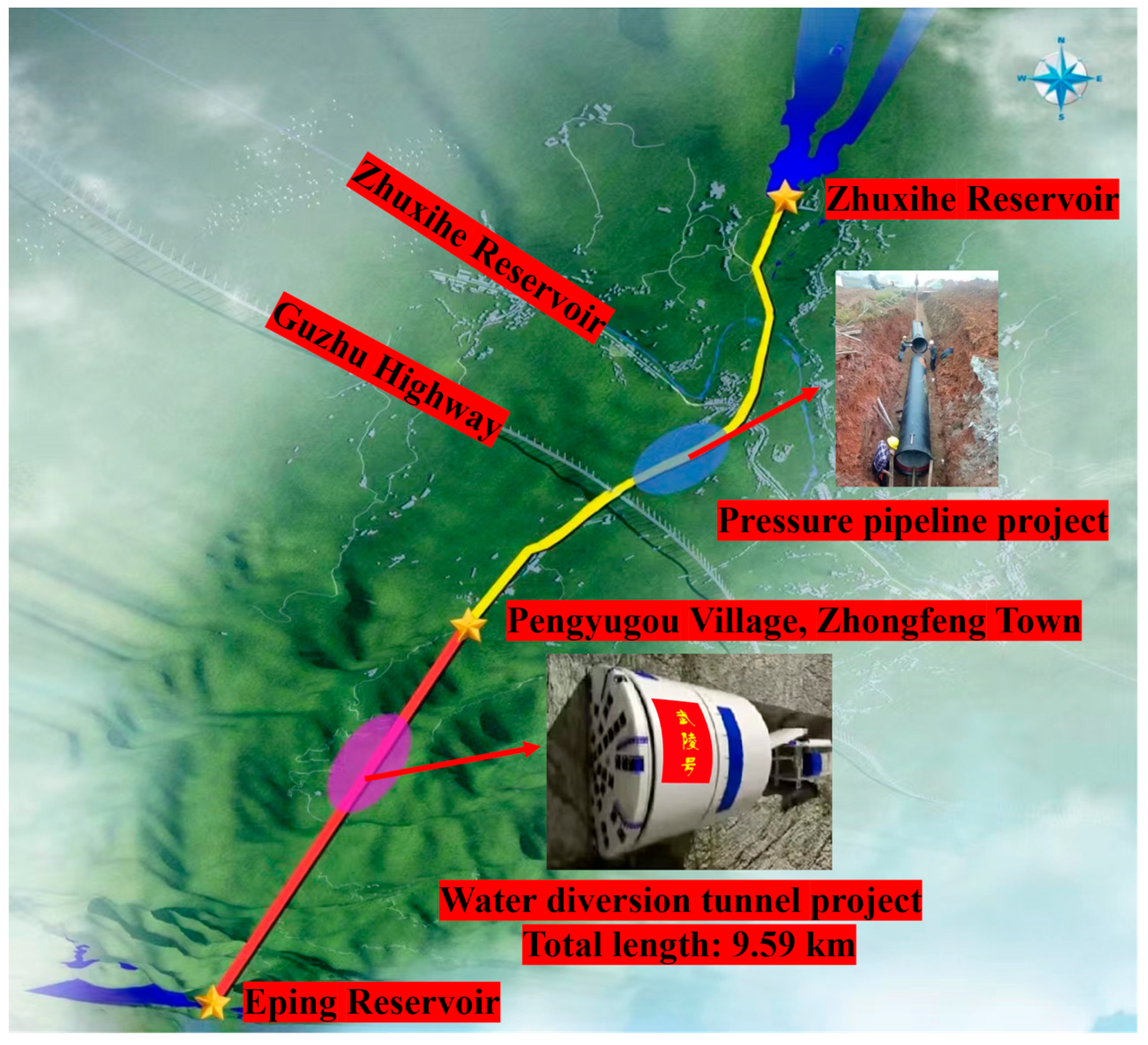
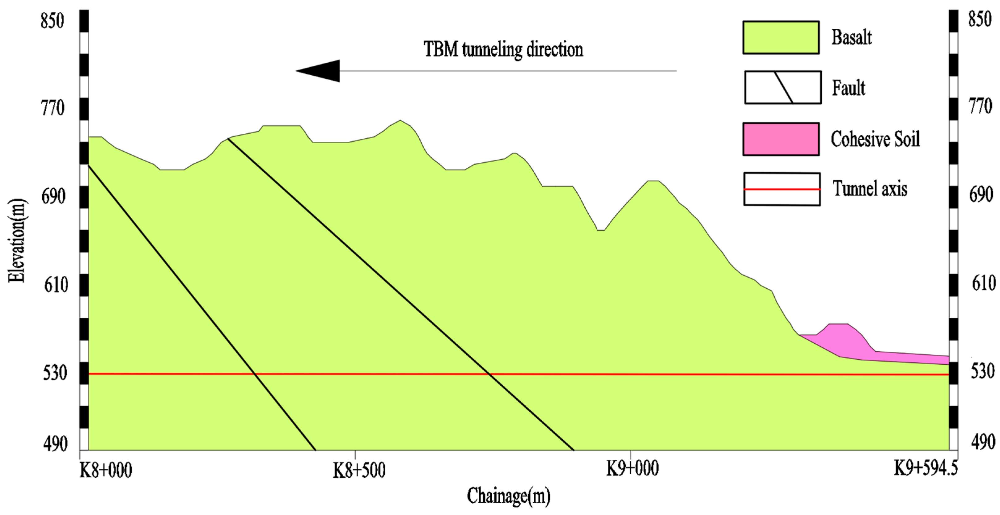
2.1. Project Overview

The Eping Water Diversion Project is located in Zhuxi County, Shiyan City, Hubei Province, with a total water diversion route length of approximately 14.26 km, as shown in Figure 1. Among this, the water diversion tunnel section spans approximately 9.59 km, with the TBM-constructed tunnel section being about 9.42 km long. The excavation diameter of the tunnel is 4.03 m, and the inner diameter after lining is 3.2 m, with a longitudinal slope ratio of 1:10,000. Based on the surrounding rock classes, three types of segments with different strengths-Type A, Type B, and Type C-were designed. The segments are diamond-shaped hexagons with a thickness of 0.3 m and a ring width of 1.2 m, as shown in Figure 2. Each ring consists of four segments, which are interlocked during assembly. The longitudinal and circumferential joints of the segments are staggered, ensuring good overall structural stability.
The water diversion tunnel passes through the Longwangya east–west ridge watershed, with elevations ranging from 1270 to 1497.7 m and a maximum tunnel burial depth of approximately 790 m. The tunnel crosses multiple fault zones, among which the larger ones include the Luohejie-Wangjiahe Fault. This fault runs east–west, extending from Longwangya through Wangjiahe to Luohejie in Shaanxi Province, where it turns northwest and intersects with the Shiziba Fault. The southern side of the fault has shifted westward, with a maximum displacement of 4.5 km and a fracture zone width of 0.5–1.0 km. The fault valley is well developed, and the topography is highly distinct. The lithology of the strata traversed by the tunnel is complex, with basalt being the predominant rock type exposed along the tunnel route.
The data for this study were obtained from the TBM tunneling section between chainage E9 + 559.9 m and E8 + 469.2 m, with a tunneling length of approximately 1.09 km. The engineering geological conditions of this section are shown in Figure 3. According to the HC method for rock mass classification [24], the tunneling section involves four classes of surrounding rock: Class II, Class III, Class IV, and Class V. Among these, Class II surrounding rock accounts for 52.10%, Class III for 22.79%, Class IV for 12.79%, and Class V for 12.33%.

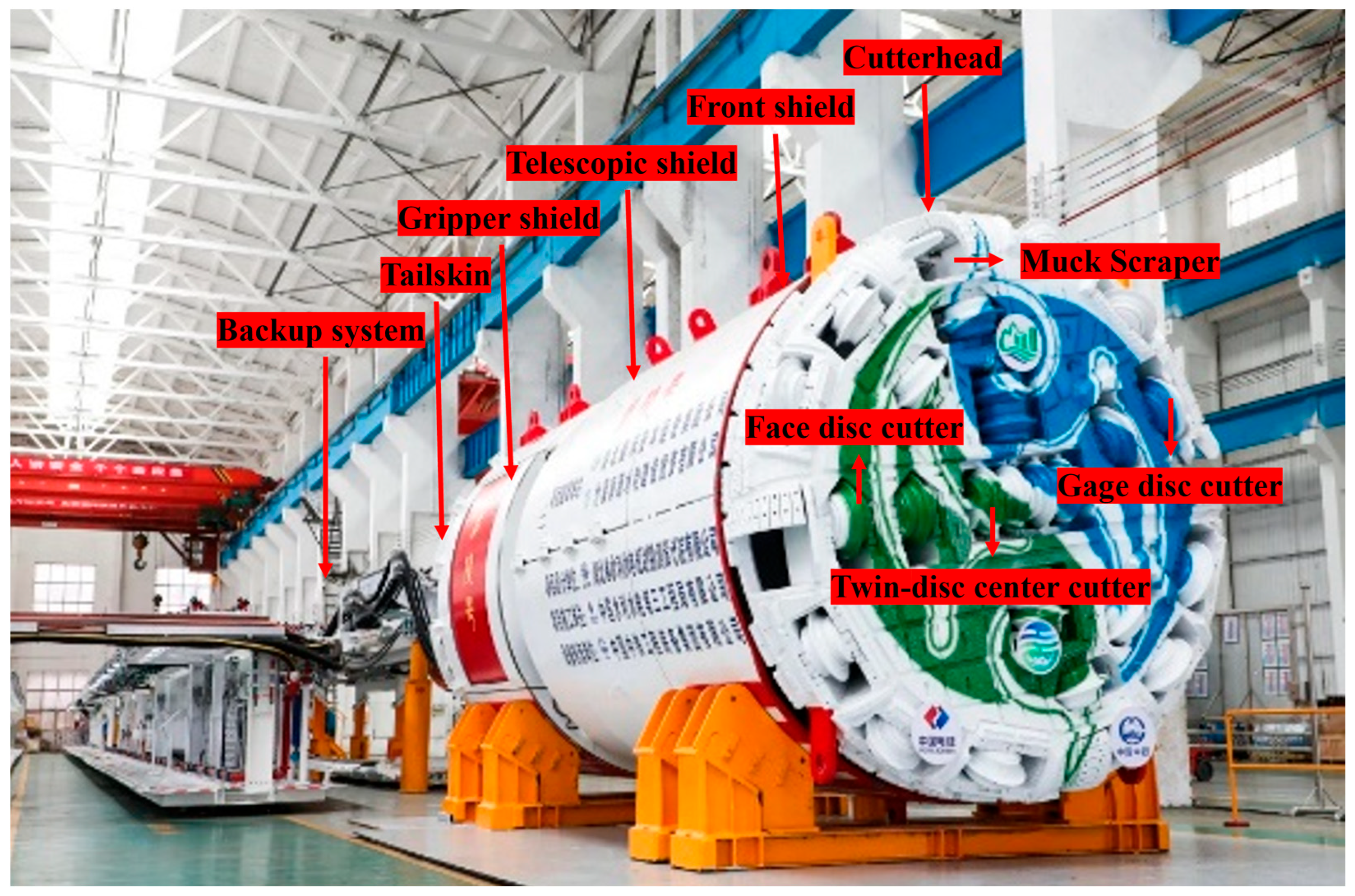
2.2. Double-Shield TBM

The water diversion tunnel was constructed using the “Wuling” double-shield TBM, jointly developed by China Railway Equipment and Sinohydro Bureau 3 Co., Ltd. (Xi’an, China). The “Wuling” double-shield TBM consists of a main machine and a rear support trolley, as shown in Figure 4. The main machine is approximately 10 m long, with a total machine length of about 428 m and a total weight of around 900 t. The minimum horizontal turning radius is 500 m. The excavation diameter of the equipment is 4.03 m. The shield adopts a stepped cylindrical design, with a front shield diameter of 3.96 m, a telescopic shield diameter of 3.95 m, and a gripper shield and tail shield diameter of 3.91 m. The thrust system of the double-shield TBM consists of a main thrust system and an auxiliary thrust system, with maximum total thrusts of 15,833 kN and 24,937 kN, respectively. The equipment has a rated torque of 2248 kN·m, a breakout torque of 3373 kN·m, a maximum rotation speed of 11.3 rpm, and a maximum tunneling speed of 120 mm/min.
The cutterhead of the “Wuling” double-shield TBM features a panel-type box structure, equipped with 25 back-loading cutters, 4 symmetrically distributed scrapers, and 6 cooling water spray nozzles, as shown in Figure 4. Among these, there are 4 double-edged center disc cutters (17 inches, numbered 1#–8#), 9 single-edged face disc cutters (19 inches, numbered 9#–17#), and 8 single-edged gauge disc cutters (19 inches, numbered 18#–25#). The disc cutters are arranged in a spiral pattern, with an average spacing of 80.6 mm and a maximum spacing of 101.6 mm.

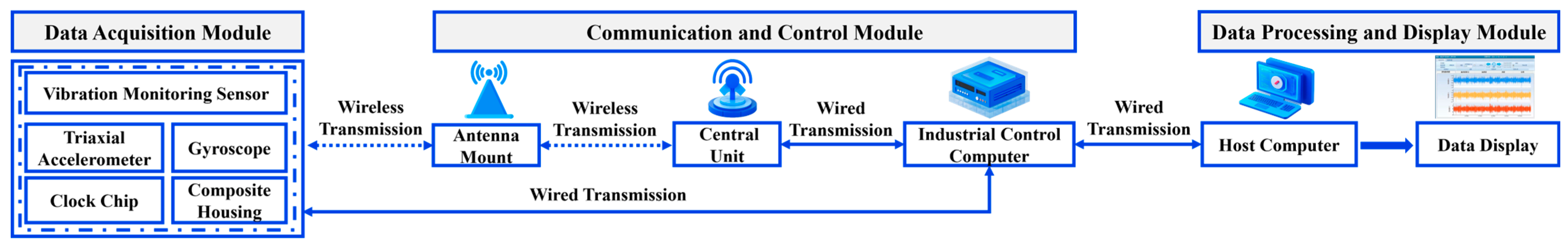
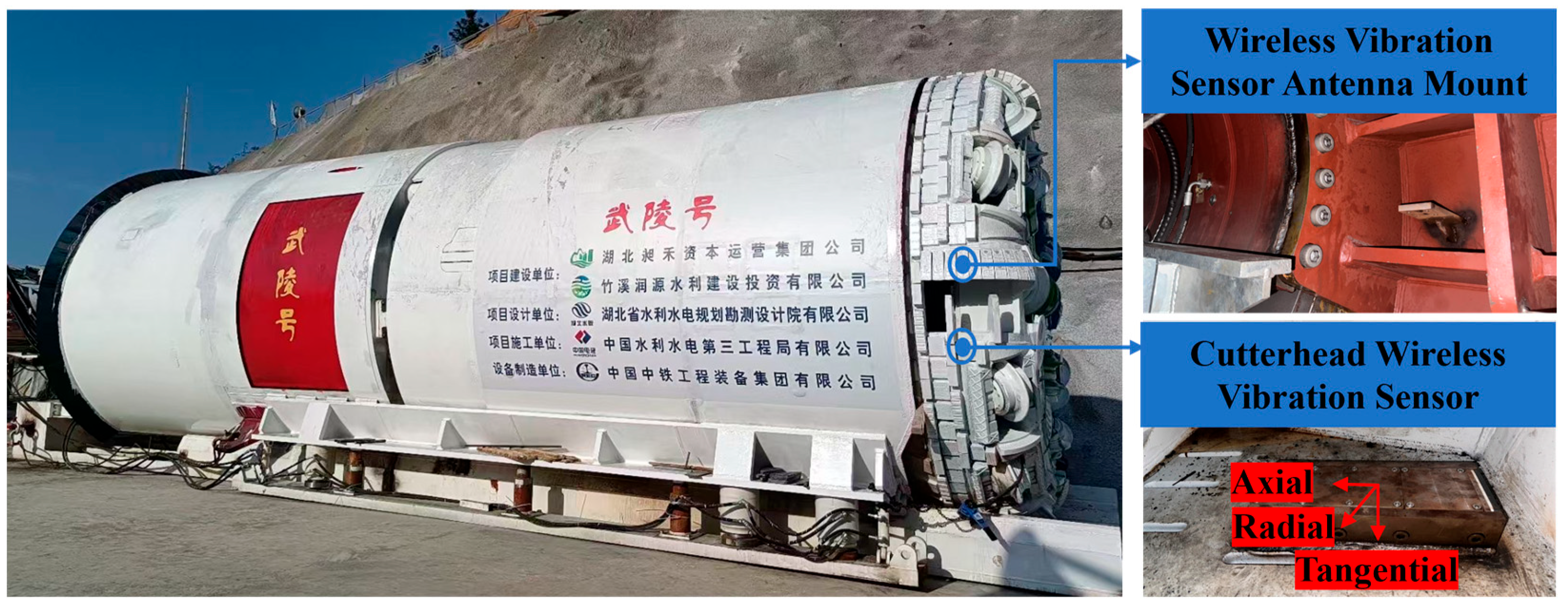
2.3. Deployment of the Double-Shield TBM Vibration Monitoring System

During the tunneling process of the TBM, the main machine generates vibration responses due to rock–machine interaction. To monitor the vibrations during the tunneling process of the double-shield TBM, a vibration monitoring system independently developed by Beijing University of Technology was employed [15]. This system primarily consists of a data acquisition module, a communication and control module, and a data processing and display module, as shown in Figure 5.
Based on the structural characteristics of the “Wuling” double-shield TBM, the sensors of the vibration monitoring system were mounted on the cutterhead through on-site welding to monitor its vibration responses. The technical specifications of the system are listed in Table 1, and the sensor installation layout is illustrated in Figure 6.

3. Vibration Signal Reconstruction and Feature Selection for Double-Shield TBM

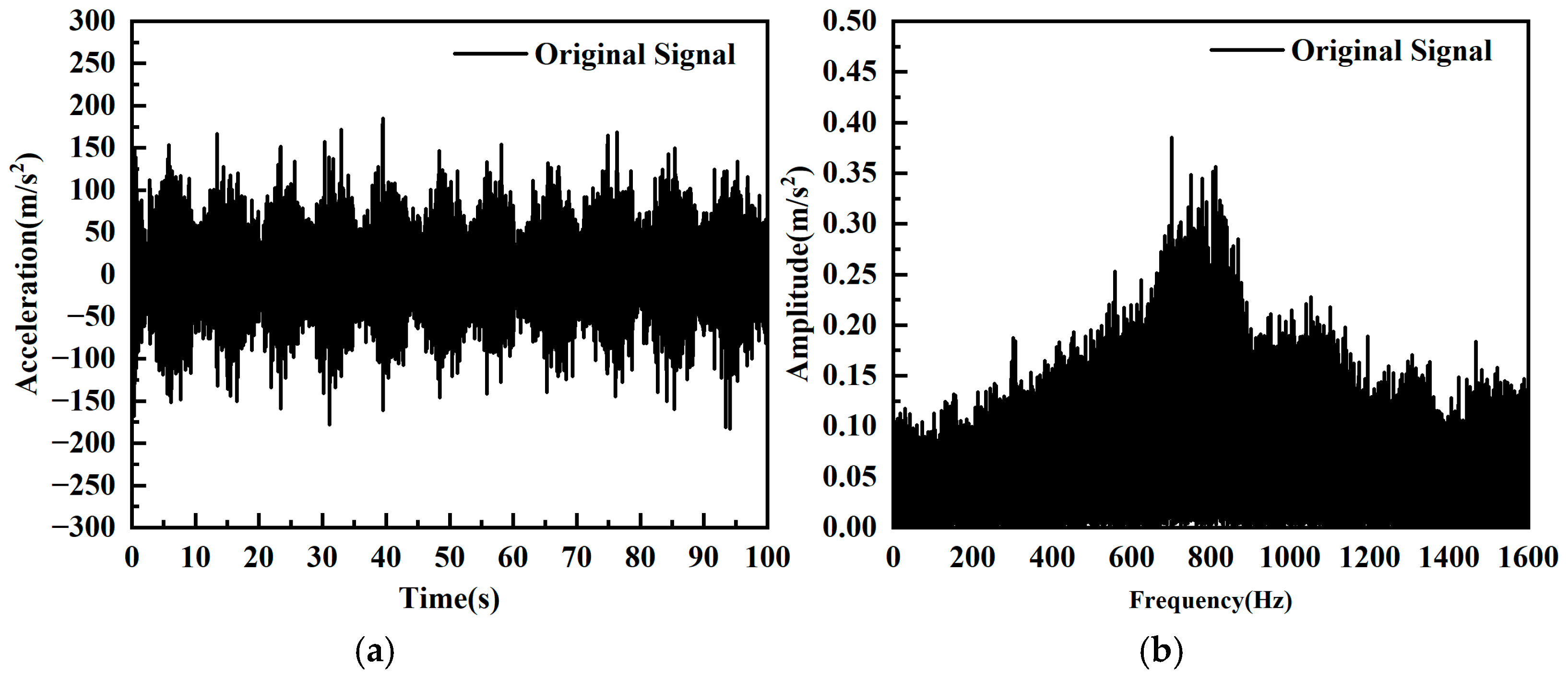
3.1. Acquisition of Vibration Signals

The data acquisition of the TBM vibration monitoring system operates in two modes: manual collection and automatic collection, which are employed during double-shield TBM tunneling tests and normal tunneling processes, respectively. In the studied tunneling section, the automatic collection mode was adopted, yielding 600 sets of cutterhead vibration monitoring data. These include 156 sets for Class II surrounding rock, 327 sets for Class III, 82 sets for Class IV, and 35 sets for Class V. The time-domain and frequency-domain characteristics of the original axial vibration signals from the double-shield TBM cutterhead are illustrated in Figure 7.

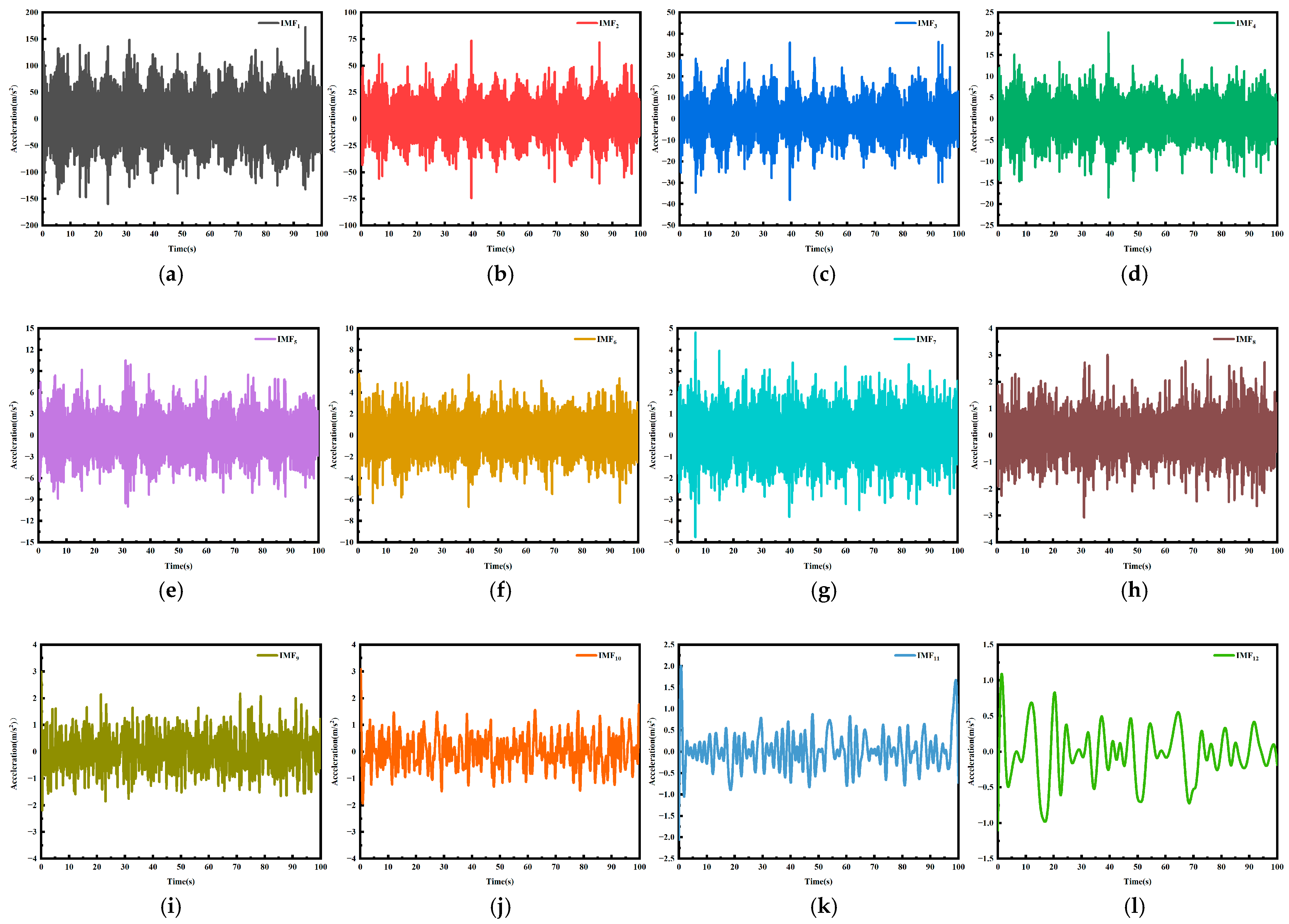
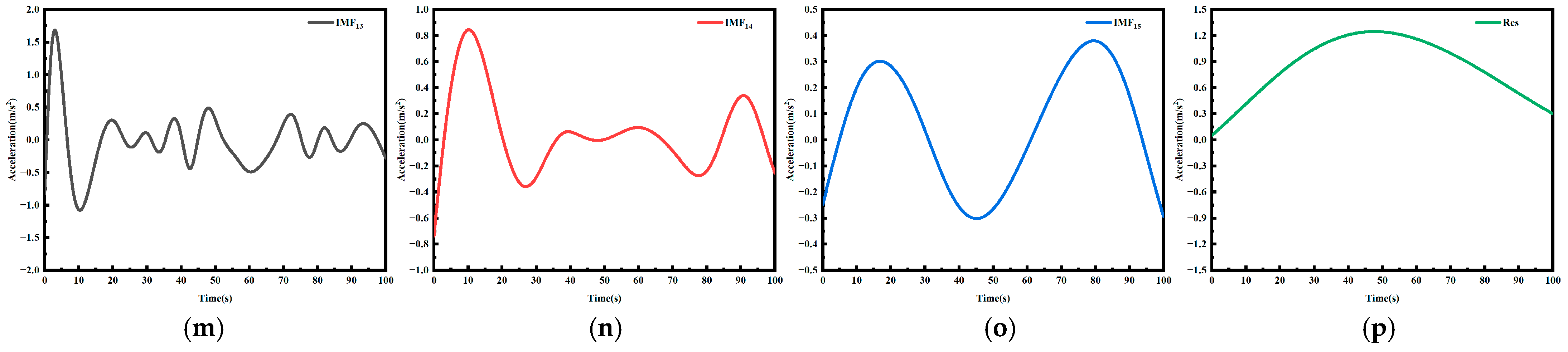
3.2. Empirical Mode Decomposition of Vibration Signals

The ICEEMDAN method [21] was employed to decompose the monitored vibration signals. Figure 7 displays the modal decomposition results obtained by applying the ICEEMDAN method to the original double-shield TBM cutterhead vibration signal presented in Figure 8.
The basic steps of the ICEEMDAN method for decomposing vibration signals are as follows:
(1) Let X(t) represent the original vibration signal, and introduce two operators, Ek(·) and M(·). Here, Ek(·) denotes the k-th Intrinsic Mode Function (IMF) component obtained by Empirical Mode Decomposition (EMD), and M(·) represents the local mean of the vibration signal.
(2) Add Gaussian white noise decomposed by EMD to the original vibration signal X(t), constructing the noise-added vibration signal Xi(t), expressed as:
X i ( t ) = X ( t ) + β 0 E 1 ( ω i ( t ) )
β0 is the standard deviation of Gaussian white noise during the first decomposition; ωi(t) is the Gaussian white noise added at the i-th iteration, with zero mean and variance; E1(·) is the function for calculating the first IMF component.
(3) Apply the EMD algorithm to decompose the noise-added vibration signal. For each Xi(t), compute the local mean and then average it to obtain the first-order residual, expressed as:
R 1 ( t ) = 1 N i = 1 N M ( X i ( t ) )
where N is the number of data points in the original signal X(t).
(4) Define k as the k-th mode generated by ICEEMDAN decomposition. When k = 1, compute the first-order IMF component IMF1 of the vibration signal, expressed as:
IMF 1 = X ( t )   -   R 1 ( t )
(5) When k = 2, compute the local mean of R1(t) after adding Gaussian white noise using EMD, obtaining the second-order residual:
R 2 ( t ) = 1 N i = 1 N M ( R 1 ( t ) + β 1 E 2 ω i ( t ) )
(6) Compute the difference between R1(t) and R2(t) to obtain the second IMF component IMF2, expressed as:
IMF 2 =   R 1 ( t )   -   R 2 ( t )
(7) For k = 3, 4, …, K, compute the k-th residual and the k-th IMF component as:
R k ( t ) = 1 N i = 1 N M ( R k - 1 ( t ) + β k - 1 E k ω i ( t ) )
IMF k = R k - 1 ( t )   -   R k ( t )
(8) Repeat step 7 until the remaining residual satisfies monotonicity, indicating the completion of decomposition.

3.3. Intrinsic Mode Function Screening and Processing

Real signals and noise-contaminated signals exhibit different behaviors in permutation entropy. Since noise increases the randomness of the signal, noise components tend to have higher permutation entropy. To screen out the key components of the vibration signal and eliminate the noise introduced by the vibration monitoring system’s sensors and the environment, the Multi-scale Permutation Entropy (MPE) method [22] was applied to each IMF component to calculate its entropy value, quantifying the extent of noise influence on the vibration signal. The specific steps of the MPE method are as follows:
(1) For a time series IMFk of length N, perform coarse-graining to obtain the coarse-grained sequence y(s)(j), expressed as:
y s ( j ) = 1 S i = j - 1 S + 1 jS IMF k ( i ) ,   j = 1 ,   2 ,   ,   [ N / S ]
where [N/S] denotes the floor division of N/S; S is the scale factor, set to 30; N is the length of the vibration signal time series.
(2) Reconstruct the phase space for the coarse-grained sequence y(s)(j), yielding:
Y s ( K ) = { y s ( K ) , y s ( K + τ ) , , y s ( K + ( m   -   1 ) τ ) }
where Y(s)(K) is the K-th reconstructed component, K = 1, 2, …, N − (m − 1)τ; τ is the time delay; m is the dimension of the reconstructed phase space.
(3) Sort each element in the reconstructed component in ascending order and extract the column indices of the element positions to form a position sequence:
S ( l ) = ( c 1 ,   c 2 ,   ,   c m )
where l = 1, 2, …, K, and lm!.
(4) There are m! possible permutation patterns for the position sequence S(l); Calculate the frequency P(S)(l) of each pattern in Y as its probability:
P S ( l ) = N l [ N / S ]   -   m + 1
(5) Based on the definition of information entropy, the permutation entropy HPK for the time series IMFk = {IMFk(i), i = 1, 2, …, N} is:
H P K = - i = 1 m ! P S ( l ) ln ( P S ( l ) )
(6) When P(S)(l) = 1/m!, HPK reaches its maximum value ln(m!); By normalizing the permutation entropy, the normalized permutation entropy HNPK at different scales is obtained as:
H NPK = H PK ln ( m ! )
The MPE method was used to calculate the entropy values of the modal components shown in Figure 8, and the results are presented in Table 2. Additionally, based on randomness detection [25], the MPE threshold was set to 0.6 to distinguish between noise-contaminated and noise-free signals. For IMF components identified as noise-contaminated, wavelet thresholding was applied for denoising, resulting in denoised IMF components. Figure 9 shows the time-domain plots of the denoised modal components (IMF1–IMF4).

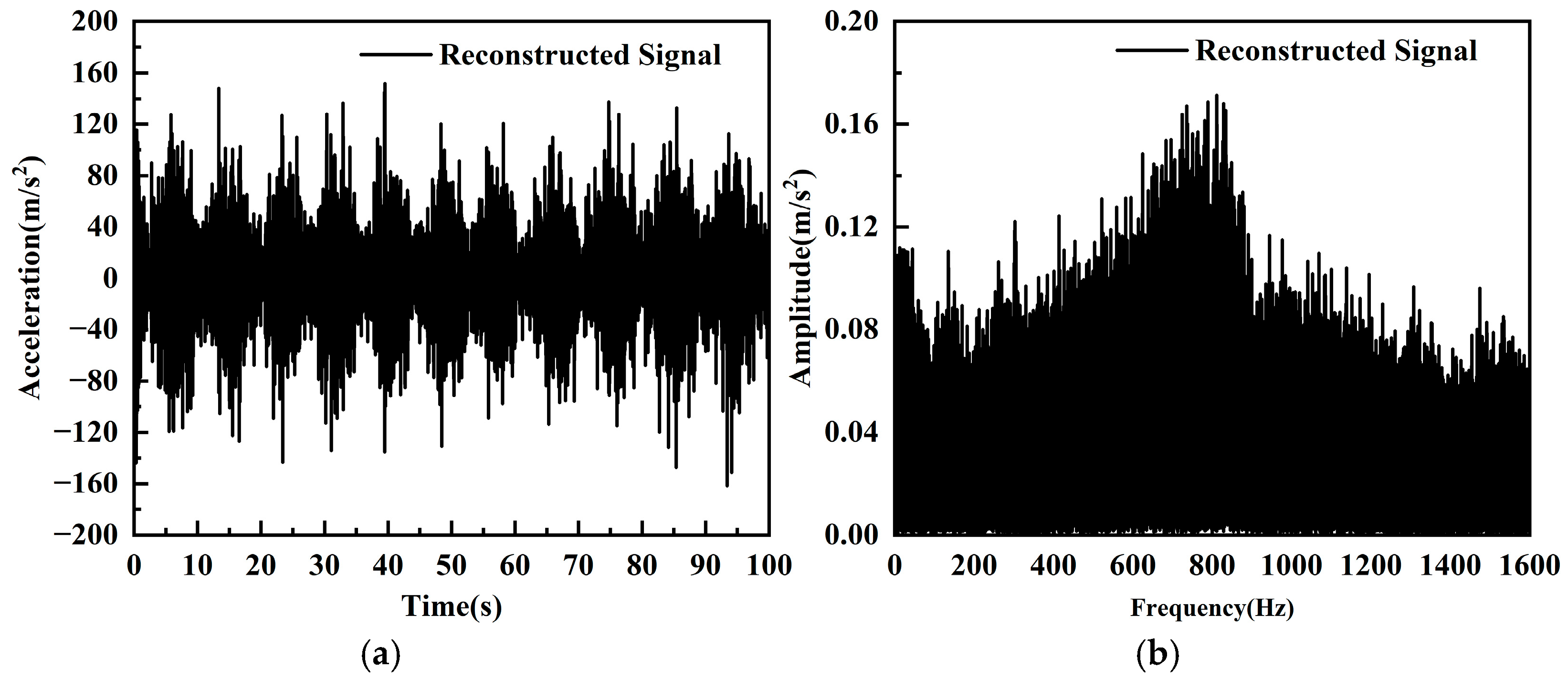
3.4. Vibration Signal Reconstruction and Feature Selection

By reconstructing the denoised IMF components, noise-free IMF components, and the residual variable Res, the denoised vibration signals during the tunneling process of the double-shield TBM were obtained. Figure 10 shows the time-domain and frequency-domain plots of the reconstructed signal corresponding to the original axial vibration signal of the cutterhead in Figure 7.
In the analysis of double-shield TBM vibration signals, six feature parameters were selected to quantitatively characterize the vibration signal properties: peak value (Xmax), rectified average value (Xrav), root mean square value (Xrms), kurtosis (Xkurt), centroid frequency (fcentroid), and root mean square frequency (frms).
Peak Value (Xmax): The maximum amplitude attainable in either positive or negative direction within a specific time period, which directly reflects the most severe vibration intensity and shows strong correlation with the generation of large rock fragments.
Rectified Average Value (Xrav): The average value of the absolute vibration signal, representing the overall amplitude characteristics without being affected by the vibration direction.
Root Mean Square Value (Xrms): The effective value of the vibration signal, stably reflecting the overall energy level of the vibration signal.
Kurtosis (Xkurt): A statistical measure quantifying the peakedness of vibration signal distribution, which serves as a sensitive indicator for identifying rock-breaking impacts in the vibration signatures.
Centroid Frequency (fcentroid): The frequency corresponding to the centroid of the vibration signal’s power spectrum, indicating the main frequency concentration area of vibration energy.
Root Mean Square Frequency (frms): Reflects the high-frequency components of the vibration signal energy, characterizing the bandwidth of energy distribution.
The calculations for the above vibration signal feature parameters are given by Equations (14)–(19):
X max = max x ( n )
X rav = 1 N n = 1 N x ( n )
X rms = n = 1 N ( x n ) 2 N
X kurt = n = 1 N ( x n   -   μ ) 4 ( N   -   1 ) σ 4
f centroid = 1 K ( k = 1 K ω k 2 f k   -   ( k = 1 K ω k f ( k ) ) 2 k = 1 K f ( k ) )
f rms = k = 1 K ω k 2 f ( k ) k = 1 K f ( k )
where x(n) is the vibration time series signal, n = 1, 2, …, N; N is the number of sample points; μ is the mean value of the vibration signal; σ represents the standard deviation of the vibration signal; f(k) is the power spectrum of x(n), k = 1, 2, 3, …, K; K is the number of spectral lines; ωk is the frequency value of the k-th spectral line.
These six vibration feature parameters comprehensively reflect the amplitude characteristics, energy distribution, and spectral distribution of the double-shield TBM vibration signals from both time-domain and frequency-domain perspectives. Among them, the four time-domain features-peak value, rectified average value, root mean square value, and kurtosis-intuitively reflect the amplitude characteristics, impact characteristics, and energy distribution of structural vibrations. The two frequency-domain features—centroid frequency and root mean square frequency—reveal the spectral structure of the vibration signals.
By calculating the feature parameters of the vibration signals in Figure 7 and Figure 10, it was found that the denoising method combining ICEEMDAN modal decomposition and multi-scale permutation entropy effectively reduces the noise intensity and energy of the double-shield TBM vibration signals, enhances the impact characteristics of the vibration signals, and optimizes the frequency-domain distribution of the vibration signals. The feature parameters of the cutterhead axial vibration signal before and after denoising are shown in Table 3.

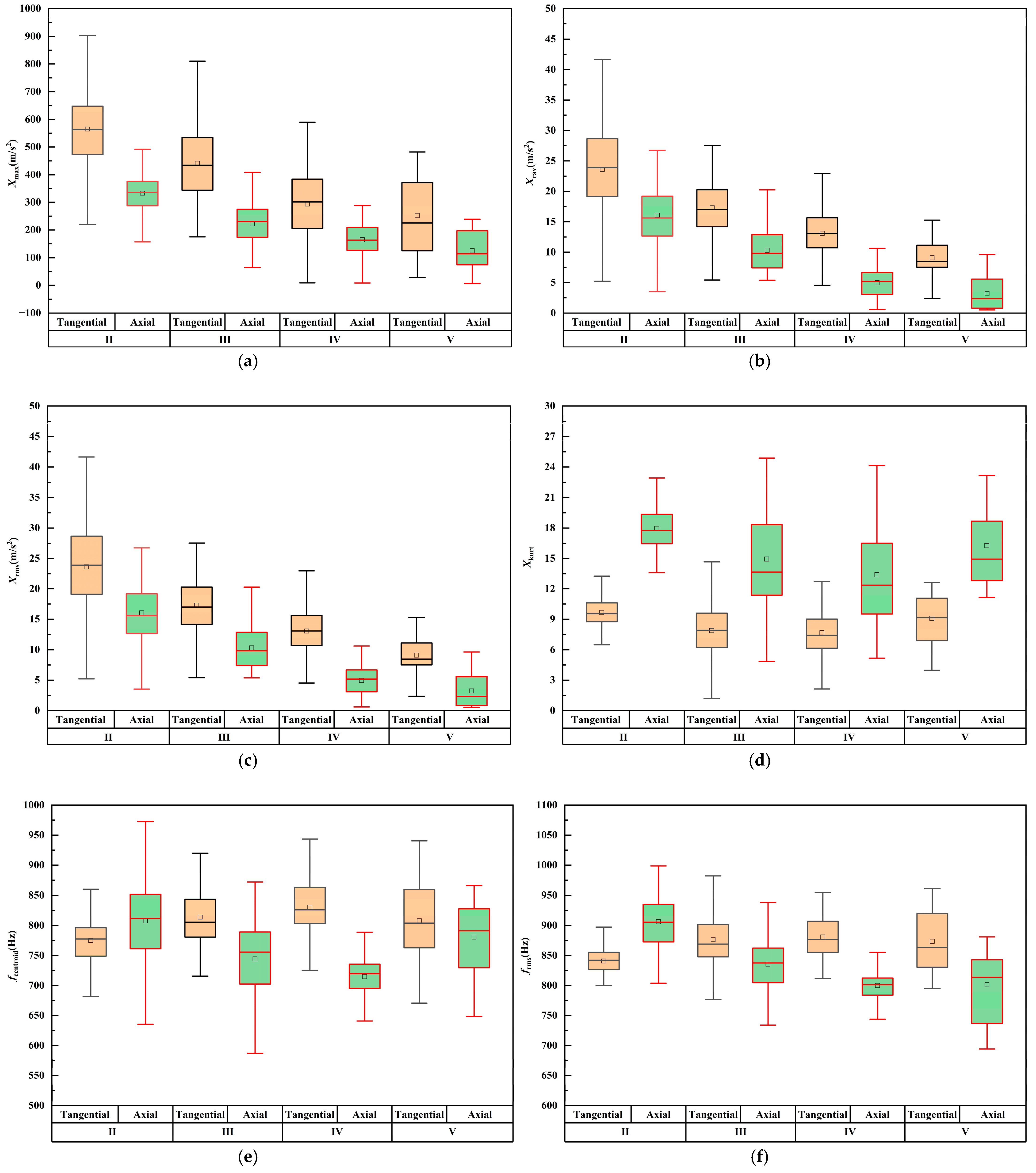
4. Vibration Characteristics of Double-Shield TBM Cutterhead

The axial, radial, and tangential directions of the vibration monitoring sensors on the double-shield TBM cutterhead correspond to the tunnel axis direction, cutterhead radial direction, and circumferential tangent direction at the monitoring point location, respectively. The reconstructed vibration signals of the double-shield TBM cutterhead were selected to calculate its vibration characteristic parameters. The distribution of tri-directional vibration characteristic parameters of the cutterhead is shown in Figure 11. By combining time-domain and frequency-domain characteristics of the signals, the tri-directional vibration characteristics of the double-shield TBM cutterhead were investigated.
From Figure 11, Based on the time-domain and frequency-domain analysis of the double-shield TBM cutterhead, the three-directional vibration characteristics exhibit significant anisotropy. The tangential vibration amplitude of the double-shield TBM cutterhead is the largest, followed by the axial, and the radial is the smallest. This is because, during the stable tunneling phase of the double-shield TBM, the cutting tools on the cutterhead mainly engage in rock cutting, and the tangential force generated by the rotational motion of the tools continuously overcomes the shear strength of the rock mass. When the rock mass undergoes shear failure, instantaneous stress release occurs at the tool-rock interface, inducing high-frequency impact vibrations. The asymmetric distribution of tools on the cutterhead panel, low integrity of surrounding rock, and heterogeneity of the rock mass all contribute to the high amplitude and strong dispersion characteristics of the tangential vibration of the cutterhead. The axial vibration of the double-shield TBM cutterhead is related to its main propulsion system. The thrust provided by the main propulsion system forms a dynamic pressure balance at the cutterhead-rock interface, and the root mean square value of its axial vibration reflects the vibration intensity. Notably, the kurtosis of the axial vibration of the cutterhead is significantly higher than that of the tangential and radial vibrations, indicating the presence of intermittent impact loads in the axial direction, which is closely related to the local fragmentation of the rock mass caused by tool intrusion. The radial vibration amplitude is the smallest due to the small lateral constraints and lateral loads on the tools. The vibration energy of the double-shield TBM cutterhead is mainly concentrated in the high-frequency range of 700–850 Hz, indicating that the cutterhead vibration is primarily influenced by the high-frequency impact between the tools on the cutterhead panel and the rock mass. Among them, the centroid frequency and root mean square frequency of the tangential vibration are higher than those of the axial and radial vibrations, fully demonstrating that the tangential vibration energy is more concentrated, which is related to the instantaneous energy release during rock fracture in the process of cutterhead rotation and rock cutting. In addition, the three-directional vibration frequencies of the cutterhead are significantly higher than the fundamental frequency of the cutterhead rotation, fully indicating that the vibration excitation of the cutterhead during stable tunneling of the double-shield TBM originates from the microscopic fragmentation process at the interface between the tools and the rock mass on the cutterhead, rather than macroscopic mechanical motion.

5. Analysis of Factors Influencing Vibration of Double-Shield TBM Cutterhead

5.1. Influence of Surrounding Rock Classes on Vibration of Double-Shield TBM Cutterhead

The rock–machine interaction mechanism of the double-shield TBM varies significantly across different surrounding rock classes, indicating a close relationship between the rock-breaking vibrations of the cutterhead and geological conditions. A total of 600 sets of reconstructed vibration signals of the double-shield TBM cutterhead under different surrounding rock classes were selected. By analyzing the time-domain and frequency-domain characteristics of these signals, the vibration characteristics of the cutterhead under various surrounding rock conditions were studied. Among these, 156 sets correspond to Class II surrounding rock, 327 sets to Class III, 82 sets to Class IV, and 35 sets to Class V. Considering that the axial and tangential vibrations of the double-shield TBM cutterhead are the most intense, the vibration characteristic parameters of the cutterhead were calculated, as shown in Figure 12.
From Figure 12, it can be observed that in terms of time-domain characteristics, as the surrounding rock class changes from Class II to Class V, the peak values, rectified average values, and root mean square values of the axial and tangential vibrations of the cutterhead during stable tunneling gradually decrease. This indicates that the higher the surrounding rock class, the lower the vibration intensity of the cutterhead. Additionally, within the same surrounding rock class, the vibration responses differ across directions. The peak values, rectified average values, and root mean square values of tangential vibrations are greater than those of axial vibrations, suggesting that tangential vibrations are more intense during the rotational rock-cutting process. Notably, the kurtosis of axial vibrations is the highest in Class II surrounding rock, primarily because Class II rock has higher strength and better integrity, leading to sudden load impacts during the rock-breaking process. In terms of frequency-domain characteristics, as the surrounding rock class changes from Class II to Class V, the centroid frequency and RMS frequency of the axial vibrations first decrease and then increase, while those of the tangential vibrations first increase and then decrease. This is because, from Class II to Class IV surrounding rock, the rock conditions deteriorate, and the rock-breaking mode transitions from intact rock breaking to joint-involved rock breaking. The cracks formed by tool intrusion connect with joint fractures, causing large rock fragments to spall from the tunnel face, resulting in an uneven face. In the axial direction, since most of the rock fragments spall in large blocks, the number of rock chips generated by tool cutting decreases, reducing the high-frequency impacts on the cutterhead. Consequently, the vibration energy is distributed more toward the low-frequency range, leading to a decrease in the centroid frequency and RMS frequency of axial vibrations. However, in the tangential direction, due to the uneven tunnel face, tools frequently collide with the irregular rock surface during cutterhead rotation, increasing the impacts during rock cutting and causing a rise in the high-frequency components of tangential vibrations. As a result, the centroid frequency and RMS frequency of tangential vibrations increase. When the surrounding rock class is Class V, the rock conditions are the poorest, and the double-shield TBM operator ensures safety by controlling the tunneling process with lower thrust and reduced rotational speed. Under low thrust conditions, the uneven load distribution at the cutterhead-rock interface, caused by the fragmented and low-strength rock mass, increases the irregularity of axial vibrations, concentrating the vibration energy in the high-frequency range. This is reflected in the increase in the centroid frequency and RMS frequency of axial vibrations. Under low rotational speed conditions, the cutting process becomes relatively stable, reducing the high-frequency impacts between tools and the rock mass. Consequently, the vibration energy shifts toward the low-frequency range, and the centroid frequency and RMS frequency of tangential vibrations slightly decrease.

5.2. Influence of Tunneling Parameters on Vibration of Double-Shield TBM Cutterhead

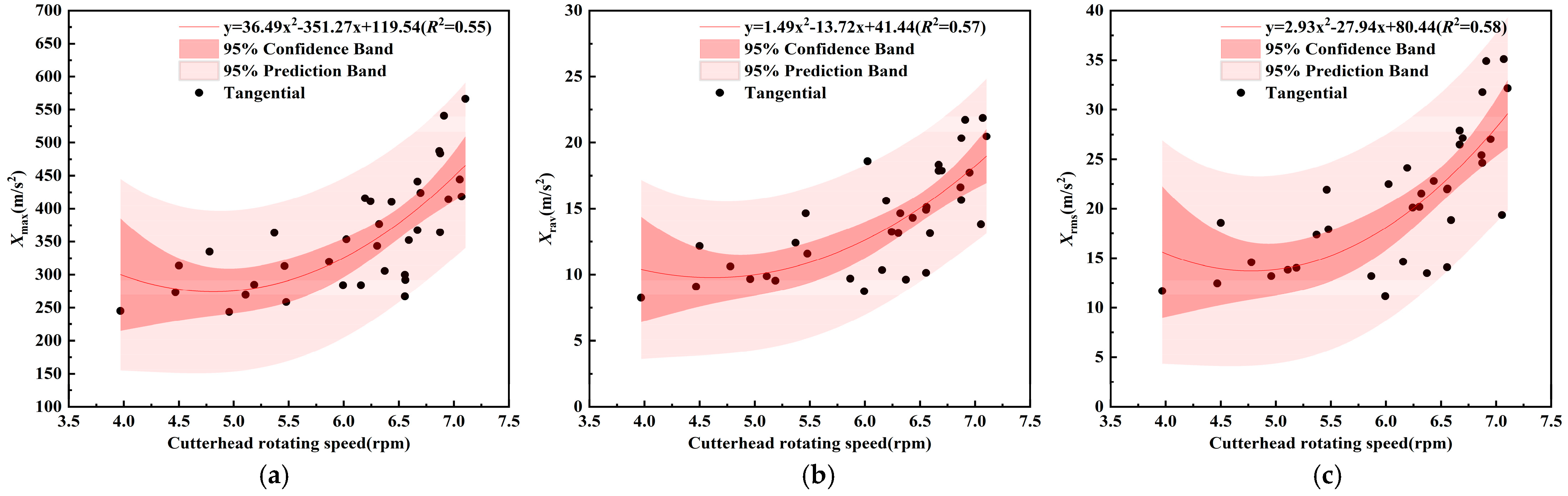
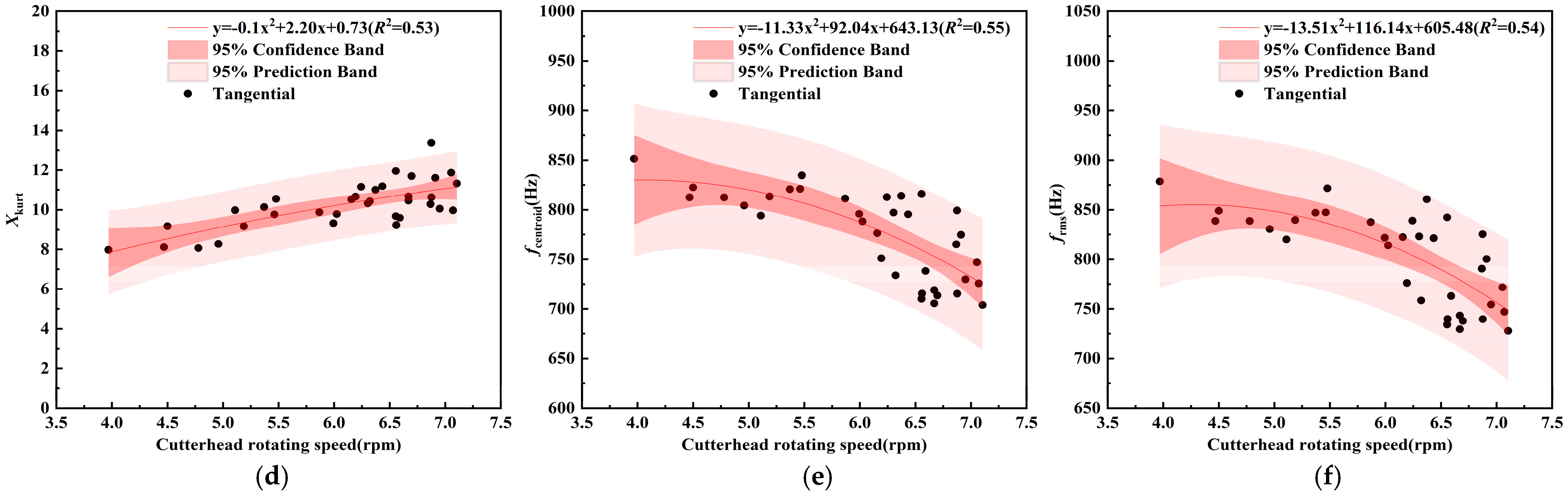
5.2.1. Influence of Cutterhead Rotational Speed on Vibration of Double-Shield TBM Cutterhead

The rotational speed of the cutterhead is one of the primary control parameters during the tunneling process of a double-shield TBM, directly affecting the vibration characteristics of the cutterhead. A total of 35 sets of reconstructed vibration signals of the cutterhead were selected under Class III surrounding rock conditions, with the total thrust of the double-shield TBM ranging from 3800 to 4100 kN. The characteristic parameters of the vibration signals were calculated. Additionally, a quadratic function was used to fit the relationship between the cutterhead rotational speed and the vibration characteristic parameters. The goodness-of-fit (R2) was no less than 0.5, indicating that the model has good explanatory power. As shown in Figure 13 and Figure 14, a systematic study of the time-frequency domain characteristics of the cutterhead vibration signals was conducted to reveal the vibration patterns of the double-shield TBM cutterhead under different rotational speeds.
From Figure 13 and Figure 14, it can be observed that in terms of time-domain characteristics, as the cutterhead rotational speed gradually increases, the peak values, rectified average values, root mean square values, and kurtosis of the cutterhead vibrations in both the axial and tangential directions also increase. This is because an increase in rotational speed leads to a higher frequency of rock-breaking impacts by the cutterhead tools, intensifying the transient energy release during brittle rock fracture, thereby increasing both the vibration intensity and kurtosis. In terms of frequency-domain characteristics, as the cutterhead rotational speed gradually increases, the centroid frequency and RMS frequency of the cutterhead vibrations in both the axial and tangential directions gradually decrease. This is due to the redistribution of vibration energy during the rock-breaking process at higher rotational speeds. When the rotational speed increases, the impact frequency of tool-rock interaction rises, resulting in more frequent rock fragmentation. The superposition of numerous small-scale rock fragmentation events causes the vibration energy to disperse over a wider frequency range. Compared to low rotational speeds, at high rotational speeds, the vibration energy is no longer concentrated in the higher frequency range but shifts and spreads more toward the lower frequency range. Furthermore, the increased dynamic imbalance of the cutterhead at higher rotational speeds generates periodic excitation loads with lower dominant frequencies. These low-frequency periodic excitation loads gradually account for a larger proportion of the vibration energy composition, further reducing the centroid frequency and RMS frequency of the cutterhead vibrations in both the axial and tangential directions.

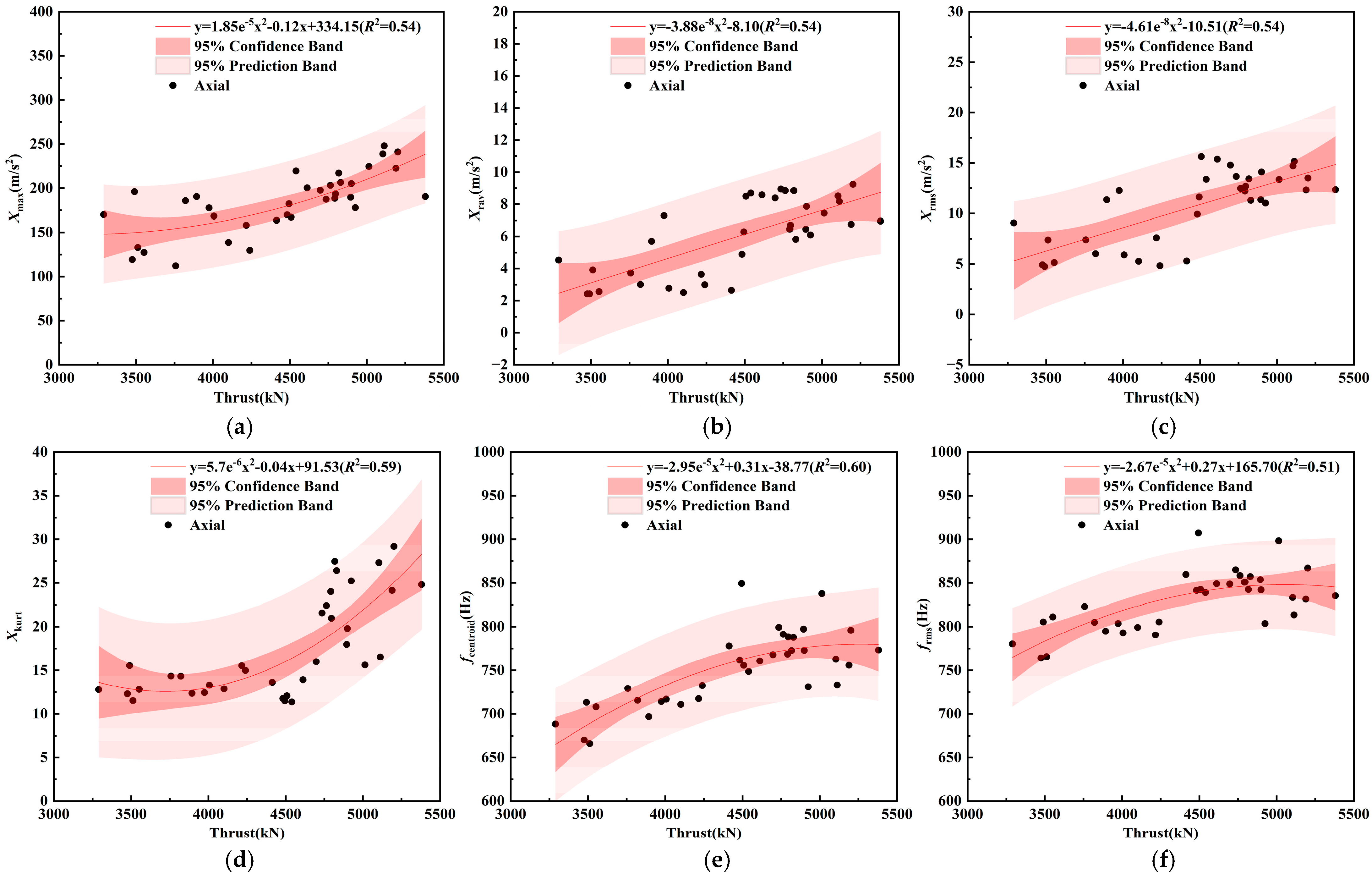
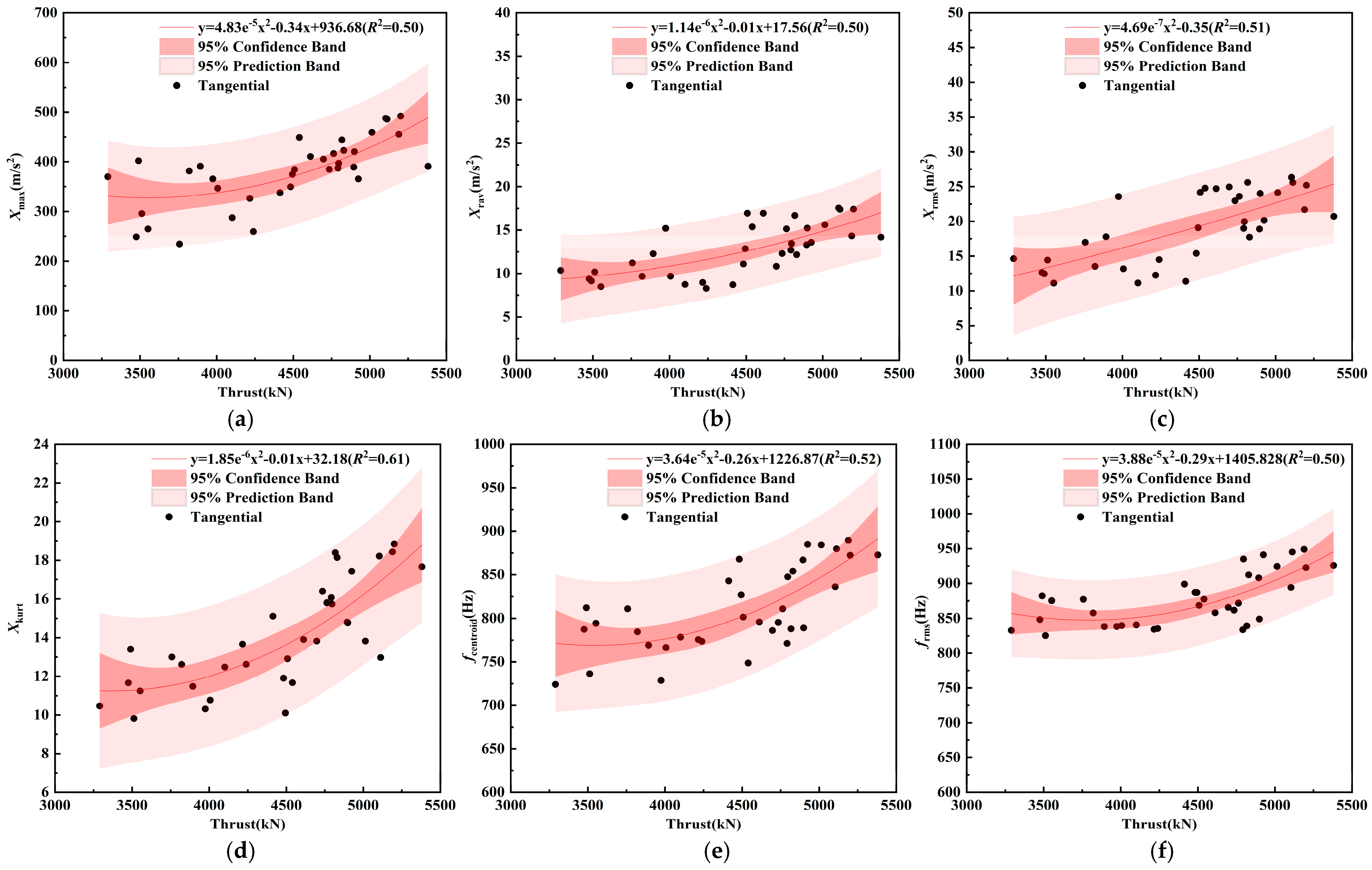
5.2.2. Influence of Thrust on Vibration of Double-Shield TBM Cutterhead

Thrust is one of the primary control parameters during the tunneling process of a double-shield TBM, directly influencing the vibration characteristics of the cutterhead. Similarly, 35 sets of reconstructed vibration signals of the cutterhead were selected under Class III surrounding rock conditions, with the cutterhead rotational speed fixed at 6 r/min. The characteristic parameters of the vibration signals were calculated. A quadratic function was used to fit the relationship between thrust and the vibration characteristic parameters, with the goodness-of-fit (R2) exceeding 0.5, indicating that the model has good explanatory power. As shown in Figure 15 and Figure 16, the time-domain and frequency-domain characteristics of the cutterhead vibration signals were analyzed to study the vibration patterns of the double-shield TBM cutterhead under different thrust conditions.
From Figure 15 and Figure 16, it can be observed that in terms of time-domain characteristics, as the thrust gradually increases, the peak values, rectified average values, root mean square values, and kurtosis of the cutterhead vibrations in both the axial and tangential directions show a gradual upward trend. This is because, as the thrust increases, the interaction strength between the cutterhead and the rock mass significantly intensifies, leading to more pronounced fluctuations in the instantaneous loads experienced by the cutterhead during rock breaking. Additionally, due to the heterogeneity of the rock mass, under high thrust conditions, the cutterhead is prone to localized stress concentration, increasing the frequency of transient spike components in the vibration signals. This results in an increase in the rectified average values and root mean square values of the vibration signals. Moreover, the increase in transient spike components causes the distribution of the vibration signals to deviate further from a normal distribution, reflected in the gradual increase in kurtosis. In terms of frequency-domain characteristics, as the thrust gradually increases, the centroid frequency and RMS frequency of the cutterhead vibrations in both the axial and tangential directions also increase. This is because, with higher thrust, the interaction strength between the cutterhead and the rock mass increases, leading to greater energy transfer to the cutterhead per unit time. This intensifies the impact strength of the tools during rock breaking, exciting more high-frequency vibrations. In the axial direction, the increase in thrust amplifies the localized stress concentration effect as the cutterhead overcomes rock resistance, causing rapid release of elastic strain energy in the rock and generating high-frequency stress waves. This results in an increase in the centroid frequency and RMS frequency of axial vibrations. In the tangential direction, the increase in thrust raises the contact pressure between the tool edges and the rock. The combined effects of frictional vibrations during cutting and the ejection of rock fragments induce high-frequency vibrations, leading to an increase in the centroid frequency and RMS frequency of tangential vibrations as well.

6. Conclusions and Future Work

This study was based on the TBM tunneling project of the Eping Water Diversion, where an independently developed vibration monitoring system from Beijing University of Technology was installed on a double-shield TBM to collect raw vibration signals during the tunneling process. Subsequently, a denoising method combining ICEEMDAN modal decomposition with multis-cale permutation entropy was employed to reconstruct the original vibration signals of the double-shield TBM, from which time-domain and frequency-domain characteristics were extracted. Finally, by analyzing the vibration signal features of the double-shield TBM cutterhead, the vibration characteristics under rock–machine interaction excitation were investigated, revealing the influence patterns of surrounding rock classification and tunneling parameters on cutterhead vibration characteristics. These findings provide valuable references for structural design, tunneling parameter optimization, geological condition perception, as well as fault identification and prediction technologies for double-shield TBMs, thereby promoting green and intelligent tunneling construction. The main research conclusions are as follows:
(1) The proposed denoising method combining ICEEMDAN and multi-scale permutation entropy effectively reduces the noise intensity and energy of the double-shield TBM vibration signals, enhances the impact characteristics of the signals, effectively suppresses noise interference, and optimizes the frequency-domain distribution. By extracting features from the reconstructed vibration signals, the amplitude characteristics, impact characteristics, energy distribution, and spectral distribution of the double-shield TBM vibration signals can be comprehensively and quantitatively described in both the time and frequency domains.
(2) During stable tunneling, the cutterhead vibration exhibits significant anisotropy, with the highest amplitude in the tangential direction, followed by axial and radial vibrations. The vibration energy is predominantly concentrated in high-frequency bands, particularly in the tangential direction. The vibration frequencies far exceed the cutterhead’s rotational fundamental frequency, indicating that the vibrations are primarily induced by high-frequency impacts between cutters and rock rather than macroscopic mechanical motion.
(3) As the surrounding rock classes changes from Class II to Class V, the vibration intensity of the cutterhead gradually decreases, and the centroid frequency and RMS frequency of the axial and tangential vibrations show different trends. Specifically, from Class II to Class IV surrounding rock, changes in rock conditions lead to a transition in the rock-breaking mode of the tools, resulting in a decrease in axial vibration frequency and an increase in tangential vibration frequency. When the surrounding rock class is Class V, the double-shield TBM operator ensures safety by controlling the tunneling process with lower thrust and reduced rotational speed. The lower thrust causes uneven load distribution at the cutterhead–fragmented rock interface, leading to a slight increase in axial vibration frequency, while the lower rotational speed results in a relatively stable cutting process, causing a slight decrease in tangential vibration frequency.
(4) The rotational speed and thrust of the cutterhead, as the primary control parameters during TBM tunneling, have different effects on the vibration characteristics of the cutterhead. When the rotational speed increases, both the vibration intensity and kurtosis in the time-domain characteristics increase, while the centroid frequency and RMS frequency in the frequency-domain characteristics decrease. This indicates that at higher rotational speeds, the vibration energy of the cutterhead shifts toward the low-frequency range. When the thrust increases, both the vibration intensity and kurtosis in the time-domain characteristics increase, and the centroid frequency and RMS frequency in the frequency-domain characteristics also increase. This indicates that at higher thrust levels, the overall vibration intensity of the cutterhead increases, with more high-frequency components.
This study focuses on the vibration characteristics of double-shield TBM cutterheads; However, several limitations and future research directions remain. Firstly, constrained by the TBM types and available construction data, this research did not comprehensively analyze the vibration characteristics and differences among open-type, single-shield, and double-shield TBMs. Subsequent studies should employ numerical simulations and field monitoring to reveal the vibration features across different TBM types. Furthermore, future work should involve continuous field monitoring at TBM construction projects to collect additional data. Through theoretical analysis and data mining of multi-source heterogeneous field data, the quantitative relationships among tunneling parameters, vibration parameters, and rock mass parameters will be examined to establish a dynamic rock mass perception model that integrates tunneling and vibration parameters. Based on the dynamic perception model, a TBM tunneling parameter optimization model will be developed with the objectives of “safety, stability, and efficiency”. This model will use cutterhead rotation speed and advance rate as control parameters, while incorporating constraints such as thrust, torque, and cutterhead vibration. The optimization goals will focus on enhancing advance speed and reducing rock-breaking energy consumption. The finalized model will be applied to field TBM construction projects to advance intelligent TBM-assisted tunneling.

Author Contributions

G.Z.: Writing—original draft, Methodology, Data curation. Q.S.: Supervision. Q.G.: Writing—review and editing, Project administration, Conceptualization. D.L. (Dongxing Liu): Writing—review and editing, Supervision, Conceptualization. D.L. (Dongwei Li): Data curation. M.S.: Data curation. All authors have read and agreed to the published version of the manuscript.

Funding

This research received no external funding.

Data Availability Statement

The authors do not have permission to share data.

Conflicts of Interest

Authors Qing Song and Dongwei Li were employed by the company Power China, Sinohydro Bureau 3 Co., Ltd. The remaining authors declare that the research was conducted in the absence of any commercial or financial relationships that could be construed as a potential conflict of interest.

References

  1. Hong, K.R.; Du, Y.L.; Chen, K.; Feng, H.H.; Jia, L.H.; Xu, F. Development history, achievements, and prospects of full-face tunnel boring machines in China. J. Tunn. Constr. 2022, 42, 739–756. [Google Scholar]
  2. Zhang, Z.H.; Song, C.N.; Li, Z. Analysis of vibration characteristics of TBM cutterhead under multi-point excitation. J. Mining Mach. 2020, 48, 1. [Google Scholar]
  3. Ling, J.X.; Sun, W.; Yang, X.J.; Tong, X. Analysis of vibration response of TBM cutterhead system under multi-point distributed loads. J. Eng. Des. 2017, 24, 317–322. [Google Scholar]
  4. Huo, J.Z.; Ouyang, X.Y.; Zhang, X.; Chen, J. The influence of front support on vibration behaviors of TBM cutterhead under impact heavy loads. J. Appl. Mech. Mater. 2014, 541, 641–644. [Google Scholar] [CrossRef]
  5. Sun, H.K.; Gao, Y. Dynamic cutting force model and vibration analysis of the cutterhead in TBM. J. Rock Mech. Rock Eng. 2023, 56, 7883–7903. [Google Scholar] [CrossRef]
  6. Zou, X.Y.; Heng, H.; Mi, Y.Z.; Xie, X. A study on vibration of tunnel boring machine and the induced shield tangential force. J. Vib. Eng. Technol. 2016, 4, 373–381. [Google Scholar]
  7. Xia, Y.M.; Ma, J.S.; Li, Z.G.; Mei, Y.B.; Ji, Z.Y. Influence of key structural parameters on the dynamic characteristics of main beam TBM. J. Vib. Shock 2020, 9, 193–201. [Google Scholar]
  8. Xia, Y.M.; Qian, C.; Li, Z.G.; Mei, Y.B. Vibration characteristics of the thrust and support system of tunnel boring machines. J. Zhejiang Univ. (Eng. Sci.) 2018, 52, 233–239. [Google Scholar]
  9. Zou, X.Y.; Mi, Y.Z.; Zheng, H. Vibration characteristics of hard rock tunnel boring machine based on field tests. J. Vib. Meas. Diagn. 2017, 37, 990–995. [Google Scholar]
  10. Liu, D.X.; Xiao, Y.H.; Zhou, X.X.; Gong, Q.M.; Liu, J.H. Research on vibration characterization parameters of TBM rock-breaking cutterhead. J. Mod. Tunn. Technol. 2023, 60, 153–162. [Google Scholar]
  11. Duan, Z.Y.; Gong, Q.M.; Wang, J.; Ma, H.S.; Huang, L.; Liu, D.X.; Peng, Z.Y. Analysis of influencing parameters on rock-breaking vibration of Beishan No. 1 TBM cutterhead. J. World Nucl. Geosci. 2024, 41, 805–816. [Google Scholar]
  12. Yang, Y.L.; Du, L.J.; Li, Q.W.; Wei, F.; Zhang, X.W.; Zhao, X.B.; Wang, Z.; Liu, Y. Vibration characteristics of TBM main beam under different surrounding rock and tunneling parameters. J. Vib. Shock 2023, 42, 88–97. [Google Scholar]
  13. Wu, F.; Gong, Q.M.; Li, Z.G.; Qiu, H.F.; Jin, C.; Huang, L.; Yin, L.J. Development and application of cutterhead vibration monitoring system for TBM tunnelling. Int. J. Rock Mech. Min. Sci. 2021, 146, 104887. [Google Scholar] [CrossRef]
  14. Ugur, A.; Hanifi, C. Investigation of parameters affecting vibration patterns generated during excavation by EPB TBMs. J. Tunn. Undergr. Space Technol. 2023, 138, 105185. [Google Scholar]
  15. Liu, M.B.; Liao, S.M.; Men, Y.Q.; Xing, H.T.; Liu, H.; Sun, L.Y. Field monitoring of TBM vibration during excavating changing stratum: Patterns and ground identification. Rock Mech. J. Rock Eng. 2022, 55, 1481–1498. [Google Scholar] [CrossRef]
  16. Tang, Q.S.; Gong, Q.M.; Liu, Y.; Guli, M.; Bieke, A.; Liu, S. Tunnel face rock mass class identification based on multi-domain feature extraction and selection of TBM cutterhead vibration signals. Int. J. Rock Mech. Min. Sci. 2025, 188, 106066. [Google Scholar] [CrossRef]
  17. Ma, H.W.; Zhang, D.W.; Cao, X.G.; Dong, M.; Li, C.H. Research on vibration signal denoising method based on EMD. J. Vib. Shock 2016, 35, 38–40. [Google Scholar]
  18. Wu, Z.; Huang, N.E. A study of the characteristics of white noise using the empirical mode decomposition method. J. Proc. R. Soc. Lond. Ser. A Math. Phys. Eng. Sci. 2004, 460, 1597–1611. [Google Scholar] [CrossRef]
  19. Yeh, J.R.; Shieh, J.S.; Huang, N.E. Complementary ensemble empirical mode decomposition: A novel noise enhanced data analysis method. J. Adv. Adapt. Data Anal. 2010, 4, 135–156. [Google Scholar] [CrossRef]
  20. Torres, M.E.; Colominas, M.A.; Schlotthauer, G.; Flandrin, P. A complete ensemble empirical mode decomposition with adaptive noise. In Proceedings of the 2011 IEEE International Conference on Acoustics; Speech and Signal Processing, Prague, Czech Republic, 22–27 May 2011. [Google Scholar]
  21. Colominas, M.A.; Schlotthauer, G.; Torres, M.E. Improved complete ensemble EMD: A suitable tool for biomedical signal processing. Biomed. J. Signal Process. Control 2014, 14, 19–29. [Google Scholar] [CrossRef]
  22. Li, R.; Fan, Y.G. Fault diagnosis of high-pressure diaphragm pump check valve based on CEEMDAN Multi-scale Permutation Entropy and SO-RELM. J. Vib. Shock 2023, 42, 127–135. [Google Scholar]
  23. Li, Z.L.; Tan, Z.S.; Zhou, Z.L.; Li, L.F.; Yang, Y.; Zheng, X.H. Research on surrounding rock parameter perception technology based on TBM vibration monitoring. J. Railw. Sci. Eng. 2025, 22, 1853–1869. [Google Scholar]
  24. GB 50487-2008; Code for Engineering Geological Investigation of Water Resources and Hydropower. China Planning Press: Beijing, China, 2009.
  25. Zheng, J.D.; Cheng, J.S.; Yang, Y. Improved EEMD algorithm and its application research. J. Vib. Shock 2013, 32, 21–26. [Google Scholar]
Figure 1. Overall rendering of the project.
Buildings 15 01824 g001
Figure 2. Construction site with precast segment stockpiles.
Buildings 15 01824 g002
Figure 3. Engineering geological profile of the study section.
Buildings 15 01824 g003
Figure 4. Key components of double-shield TBM.
Buildings 15 01824 g004
Figure 5. TBM Vibration Monitoring System Framework.
Buildings 15 01824 g005
Figure 6. Layout of vibration monitoring sensors on cutterhead.
Buildings 15 01824 g006
Figure 7. Time-domain and frequency-domain representations of the original axial vibration signal from the cutterhead. (a) Time waveform, (b) frequency spectrum.
Buildings 15 01824 g007
Figure 8. Modal decomposition of the original axial vibration signal of the cutterhead. (a) IMF1 component, (b) IMF2 component, (c) IMF3 component, (d) IMF4 component, (e) IMF5 component, (f) IMF6 component, (g) IMF7 component, (h) IMF8 component, (i) IMF9 component, (j) IMF10 component, (k) IMF11 component, (l) IMF12 component, (m) IMF13 component, (n) IMF14 component, (o) IMF15 component, (p) IMF16 component.
Buildings 15 01824 g008aBuildings 15 01824 g008b
Figure 9. IMF1* to IMF4* modal components. (a) IMF1* component, (b) IMF2* component, (c) IMF3* component, (d) IMF4* component.
Buildings 15 01824 g009
Figure 10. Time-domain and frequency-domain representations of the reconstructed axial vibration signal from the cutterhead. (a) Time waveform, (b) frequency spectrum.
Buildings 15 01824 g010
Figure 11. Tri-directional vibration characteristic parameters of double-shield TBM cutterhead. (a) Xmax, (b) Xrav, (c) Xrms, (d) Xkurt, (e) Xcentroid, (f) Xrms.
Buildings 15 01824 g011
Figure 12. Vibration characteristic parameters of the cutterhead of the double-shield TBM. (a) Xmax, (b) Xrav, (c) Xrms, (d) Xkurt, (e) Xcentroid, (f) Xrms.
Buildings 15 01824 g012
Figure 13. Axial vibration characteristics of the cutterhead under different rotational speeds. (a) Xmax, (b) Xrav, (c) Xrms, (d) Xkurt, (e) Xcentroid, (f) Xrms.
Buildings 15 01824 g013
Figure 14. Tangential vibration characteristics of the cutterhead under different rotational speeds. (a) Xmax, (b) Xrav, (c) Xrms, (d) Xkurt, (e) Xcentroid, (f) Xrms.
Buildings 15 01824 g014aBuildings 15 01824 g014b
Figure 15. Axial vibration characteristics of the cutterhead under different thrust conditions. (a) Xmax, (b) Xrav, (c) Xrms, (d) Xkurt, (e) Xcentroid, (f) Xrms.
Buildings 15 01824 g015
Figure 16. Tangential vibration characteristics of the cutterhead under different thrust conditions. (a) Xmax, (b) Xrav, (c) Xrms, (d) Xkurt, (e) Xcentroid, (f) Xrms.
Buildings 15 01824 g016
Table 1. Technical parameters of the vibration monitoring system.
Mounting PositionRange (G)Resolution (bit)Accuracy (mg·LSB⁻1)Sampling
Frequency (Hz)
Sampling
Time
(s)
Transmission MethodShock
Resistance (G)
Operating
Temperature (°C)
Cutterhead±20016≤43200120Wireless10,000−40~85
Table 2. Entropy values of IMF components after ICEEMDAN decomposition of vibration signals.
IMFIMF1IMF2IMF3IMF4IMF5IMF6IMF7IMF8
MPE0.98140.89140.74070.64050.57120.48800.44040.4137
IMFIMF9IMF10IMF11IMF12IMF13IMF14IMF15IMF16
MPE0.40030.39320.38990.38800.38740.38680.38660.3863
Table 3. Comparison of axial vibration signals of the cutterhead before and after noise reduction.
CharacteristicsXmax (m/s2)Xrav (m/s2)Xrms (m/s2)Xkurtfcentroid (Hz)frms (Hz)
Original Signal184.7113.9619.903.68802.58871.95
Reconstructed Signal161.456.1610.9715.10724.40818.59
Reduction12.59%55.86%44.88%−310.24%9.74%6.12%
Disclaimer/Publisher’s Note: The statements, opinions and data contained in all publications are solely those of the individual author(s) and contributor(s) and not of MDPI and/or the editor(s). MDPI and/or the editor(s) disclaim responsibility for any injury to people or property resulting from any ideas, methods, instructions or products referred to in the content.

