Article

Parametric Analysis and Control of Bedding-Inclined Asymmetric Stress in Double-Arch Tunnels: A 3DEC-Based Study on Jointed Rock Masses

1
Shenzhen Futian Investment Holdings Co., Ltd., Shenzhen 518055, China
2
School of Intelligent Civil and Ocean Engineering, Harbin Institute of Technology, Shenzhen, Shenzhen 518055, China
3
China United Engineering Corporation, Hangzhou 310000, China
4
Guangdong Provincial Key Laboratory of Intelligent and Resilient Structures for Civil Engineering, Shenzhen 518055, China
5
School of Civil Engineering, Jiangsu College of Engineering and Technology, Nantong 226006, China
*
Author to whom correspondence should be addressed.
Buildings 2025, 15(11), 1816; https://doi.org/10.3390/buildings15111816
Submission received: 30 April 2025 / Revised: 16 May 2025 / Accepted: 20 May 2025 / Published: 25 May 2025
(This article belongs to the Special Issue Advances in Building Foundation Engineering)

Abstract

Double-arch tunnels in inclined layered jointed rock masses face risks of lining cracking and collapse under bedding-inclined asymmetric stress (BIAS); however, related studies remain limited. Based on a case study of an expressway tunnel case in Zhejiang Province, a three-dimensional discrete element model of a double-arch tunnel was developed using Three-Dimensional Distinct Element Code (3DEC) (version 7.0, Itasca Consulting Group, Inc., Minneapolis, MN, USA). The impacts of joint dip angle (0–90°) and spacing (0.5–6.5 m) on deformation, BIAS evolution, and middle partition wall stability were analyzed. Key findings reveal that joint presence significantly amplifies surrounding rock deformation, with pronounced displacement increases observed on the counter-dip side. The BIAS intensity follows a unimodal distribution with joint dip angles, peaking within the 30–60° range. Increasing joint spacing reduces BIAS effects, with a 57.1% decrease in asymmetric deformation observed when spacing increases from 0.5 m to 6.5 m. The implementation of dip-side pilot excavation with the main tunnel full-face method, combined with an optimized support strategy (installing dip-side bolts perpendicular to joints and extending counter-dip side bolt lengths from 4 m to 6 m), achieved a near-unity stress ratio between tunnel sides under equivalent overburden depths compared to conventional methods. These findings offer theoretical and technical insights for optimizing excavation and reinforcement in similar tunnel engineering contexts.

1. Introduction

With the rapid development of transportation infrastructure in China, tunnel engineering projects in highway construction have experienced significant growth [1]. Conventional highway tunnels predominantly consist of three types: separated tunnels, adjacent tunnels and multi-arch tunnels. In recent decades, multi-arch tunnels have become very popular owing to their superior alignment continuity, minimal land occupation, and enhanced spatial efficiency, with double-arch tunnels emerging as the most prevalent implementation variant. However, when double-arch tunnels traverse complex geological strata, particularly inclined layered jointed rock masses, bedding-inclined asymmetric stress (BIAS) fields induced by the surrounding rock mass may lead to differential deformation during excavation [2]. Compared with homogeneous rock masses [3,4], inclined layered masses exhibit pronounced disparities in compressive strength, deformation moduli, and failure mechanisms attributable to dominant structural planes, demonstrating significant mechanical anisotropy between orientations parallel and perpendicular to these planes. Critical discontinuity attributes—including dip angle, persistence, and shear strength—exhibit substantial influence on the mechanical response of layered rock masses, thereby modifying stress redistribution patterns and deformation behavior in the tunnel periphery [5,6,7,8,9]. Double-arch tunnel construction encounters critical stability challenges, particularly in the central partition wall. This structural element becomes vulnerable during phased excavation due to superimposed BIAS effects [10,11,12]. Therefore, investigating the deformation characteristics of surrounding rock and stability variations of middle partition walls in double-arch tunnels under different joint characteristics holds significant importance for the design and construction of such tunnels in inclined layered jointed rock masses.
Recent advancements in numerical analysis methodologies have significantly enhanced the understanding of mechanical characteristics in double-arch tunnel engineering. Substantial research efforts have been directed toward investigating critical structural components, particularly the middle partition walls [10,13,14,15,16]. Concurrently, the mechanical mechanisms and support efficacy of bolt systems have been thoroughly investigated through numerical simulations and experimental validations [17,18,19,20,21]. Notably, the three-dimensional structural responses of asymmetric double-arch tunnels subjected to void conditions have been rigorously analyzed, providing critical insights into defect-induced stress redistributions [22].
The asymmetric stress characteristics inherent in double-arch tunnel configurations have received particular attention. The authors of [23] comprehensively considered various factors including stress states, construction methods, and tunnel dimensions to systematically analyze the evolution characteristics of surrounding rock pressure during tunnel excavation, while Dancygier et al. [24] developed an innovative computational model to predict vault lining responses under surface static loads. Complementing these theoretical advances, Wang et al. [25] conducted pioneering large-scale shaking table tests to validate dynamic response simulations in asymmetrically stressed tunnel systems. Subsequent investigations have further elucidated the mechanical interaction mechanisms between double-arch tunnels and adjacent structures [26,27,28], with Ma et al. [29] establishing correlations between excavation-induced mechanical variations and structural inclination angles. The evolution of pressure arch characteristics in surrounding rock masses during excavation processes has been quantitatively characterized through advanced numerical modeling [30].
Significant progress has been achieved in understanding tunnel deformation mechanisms and stability control strategies. Integrated approaches combining theoretical analysis with numerical simulations [31,32,33,34,35,36] and field monitoring [37,38] have revealed critical factors governing tunnel deformation patterns. Specialized investigations by Wang et al. [14] decoupled the mechanical–deformation coupling effects in middle partition walls under asymmetric stress and fractured rock conditions. Ma et al. [29] employed scaled model tests to systematically analyze deformation propagation in multi-jointed rock masses during high geostress excavations. Technological innovations in monitoring techniques, particularly fiber optic sensing systems [39,40,41], have enabled precise measurement of support structure load distributions and real-time observation of lining crack evolution [42].
Construction optimization research has yielded practical engineering solutions through comparative analyses of excavation sequences. The integration of fiber optic monitoring networks [40] has facilitated the development of optimized excavation protocols [43]. Hu et al. [44] applied digital twin technology to the tunnel excavation process to enable intelligent tunnel construction. These technological advancements have directly informed the optimization of bolt support configurations and excavation schemes, significantly enhancing construction efficiency while ensuring structural safety.
However, most existing studies are based on the assumption of rock mass homogeneity and have not yet systematically conducted sensitivity analysis of joint parameters. The understanding of coupled effects between joint dip angle and spacing remains particularly limited. In this study, 3DEC (version 7.0, Itasca Consulting Group, Inc.) was utilized to simulate the construction of double-arch tunnels in inclined layered jointed rock masses. Through analysis of surrounding rock deformation characteristics, BIAS variations, and middle partition wall stability under different joint dip angles and spacings, practical design and construction recommendations are proposed, providing significant guidance for engineering practice.

2. Numerical Simulations Using 3DEC

2.1. Implementation of the Numerical Model

In addition to on-site monitoring, numerical simulations are useful for understanding the behavior of the surrounding rock masses, which can be categorized into continuum-based and discontinuum-based modeling [33,45]. Discontinuous deformations can be effectively analyzed using the Discrete Element Method (DEM), Particle Flow Code (PFC), or Universal Distinct Element Code/3DEC (UDEC/3DEC) [46,47]. The 3DEC is suitable for analyzing the deformation of solid blocks of rock. In the rock formation analyzed in this study, the rock masses are cut by spatially distributed discontinuities, which can be treated as an assembly of discrete blocks [48]. Therefore, the 3DEC was adopted to analyze the excavation of the double-arch tunnel.
In the current study, the surrounding rock was modeled using the Mohr–Coulomb elastoplastic constitutive model [49], while the secondary lining and middle partition wall were assigned to isotropic elastic models. The rock bolts were simulated with cable structural elements and the Coulomb-slip constitutive model for joint interfaces. The physical and mechanical parameters of surrounding rock and support structures for numerical model validation are detailed in Section 2.3, while those adopted in the developed numerical model of this study are specified in Section 2.4. The model was initially established through block assembly [50], followed by the construction of structural planes by inputting original coordinates, dip direction, and dip angle. The intact rock mass and structural planes were assigned corresponding constitutive models and material parameters, respectively. To avoid boundary effects [51,52,53], the model dimensions were set as detailed in Section 2.3 and 2.4, with fixed constraints applied to the base, horizontal displacement boundaries imposed on the front, back, left, and right sides, and the top boundary remaining free, as illustrated in Figure 1 (generated using 3DEC).

2.2. Excavation and Support Simulation Sequence

The double-arch tunnel adopts the central pilot tunnel–main tunnel step excavation method, with an advance length of 3 m. The simulated construction sequence was as follows: (1) excavation and primary support of the central pilot tunnel; (2) casting of the middle partition wall and lateral backfilling; (3) upper step excavation and primary support; (4) lower step excavation and primary support; (5) construction of the inverted arch and filling; (6) casting of secondary lining concrete.
The initial stress field of the surrounding rock only considers the self-weight stress and does not include tectonic stress. Excavation and secondary lining were implemented using the excavation and backfill simulation modules in the program.

2.3. Verification of Numerical Modeling

To validate the rationality of employing the 3DEC for simulating double-arch tunnel excavation, field monitoring data were compared with numerical simulation results using the multi-arch tunnel project along Nanshan Road in Jiangmen City, Guangdong Province as a verification case [54]. The tunnel spans a design chainage of K1 + 521.0–K + 70.0, with a total length of 449 m, height of 11.40 m, and width of 35.36 m. The cross-section at chainage K1 + 650 was selected as the study section, where the surrounding rock is classified as Grade V, with overburden depth of approximately 22 m for the left tunnel and 28 m for the right tunnel. The numerical model parameters were determined as follows: the tunnel model extends 30 m longitudinally (along the axis), spans 120 m horizontally (in cross-section), and covers 40 m vertically from the tunnel invert to the lower boundary, as illustrated in Figure 1. The model parameters are listed in Table 1 [54]. The initial support comprised shotcrete and rock bolt support using 28 cm thick C20 shotcrete, while the central partition wall and secondary lining utilized C35 reinforced concrete.
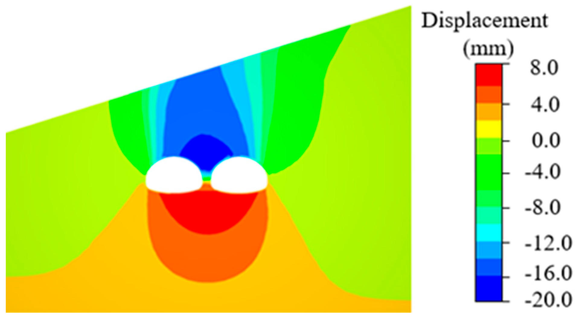
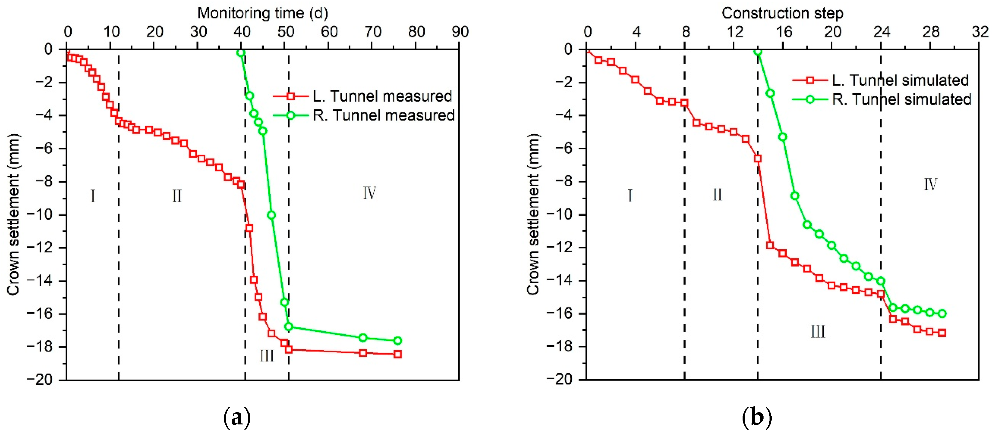
After completing the calculations, the vertical displacement contour at the intermediate cross-section (chainage K1 + 650) was extracted, as shown in Figure 2 (generated using 3DEC). Figure 3 (graphs plotted using OriginPro 2024, OriginLab Corporation, Northampton, MA, USA) compares the measured and simulated crown settlement curves of the left and right main tunnels, and their final values are summarized in Table 2. In the contour map, negative values indicate downward displacement. Figure 2 reveals that the displacement contours above the tunnel are skewed toward the left tunnel, with the left tunnel exhibiting greater crown settlement. The maximum downward displacement occurs at the top of the central partition wall. Analysis of Figure 3 indicates that both measured and simulated crown settlements of the left tunnel consistently exceed those of the right tunnel. Moreover, both tunnels’ crown settlements exhibit distinct stagewise characteristics corresponding to excavation steps, resulting in consistent trends between measured and simulated curves. Table 2 shows that the final differences in crown settlement between the left and right tunnels are 1.5 mm and 1.6 mm, respectively, with errors within 10%, indicating minor discrepancies. Thus, the numerical simulation results show good consistency with field observations, confirming that 3DEC can effectively simulate the excavation and support process of the double-arch tunnel.

2.4. Numerical Model Parameters of the Double-Arch Tunnel

The total span of the excavation section of the main tunnel under consideration is 26.4 m, and the excavation height is 10.5 m. The width and height of the central pilot tunnel are 6.8 m and 5.9 m, respectively. The shotcrete–rock bolt system was used for primary support, including 280 mm thick C30 early-strength shotcrete, and Φ22 mm hollow grouted rock bolts with a length of 4 m and a spacing of 0.8 m arranged in a staggered installation. Based on the engineering geological survey report and the Chinese Technical Standard for Highway Tunnels (JTG3370.1-2018) [55], the physical and mechanical parameters of the surrounding rock and support structures are shown in Table 3, while the joint mechanical parameters are shown in Table 4.
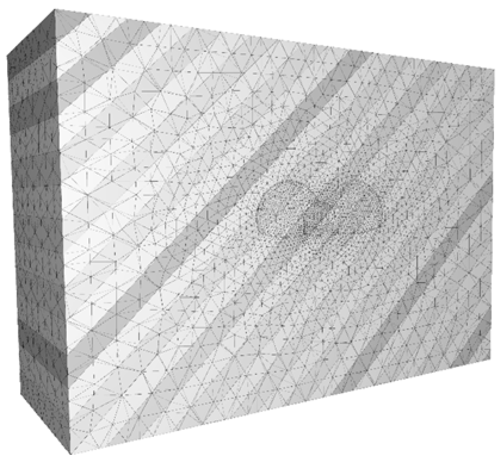
According to He and Li [51], within a range of three to five times the tunnel excavation diameter (defined as the excavation influence zone), stress changes exceeding 5% are expected; beyond this range, stress remains relatively constant. To ensure the accuracy of simulating the excavation support process, the model boundary parameters were determined as follows: the actual tunnel depth was taken as 24 m, the longitudinal extent of the tunnel model was set at 40 m, and the left, right, and bottom boundaries were each set at a distance of 35 m from the tunnel edge, satisfying the criterion of 3 to 5 times the diameter of the excavation tunnel. Figure 4 depicts the numerical model with a joint spacing of 3.5 m and an inclination angle of 45°, where the joint inclination towards the right side of the current joint is considered the dip side, while the left side is the counter-dip side.

2.5. Placement of Data Sampling Points for Model Analysis

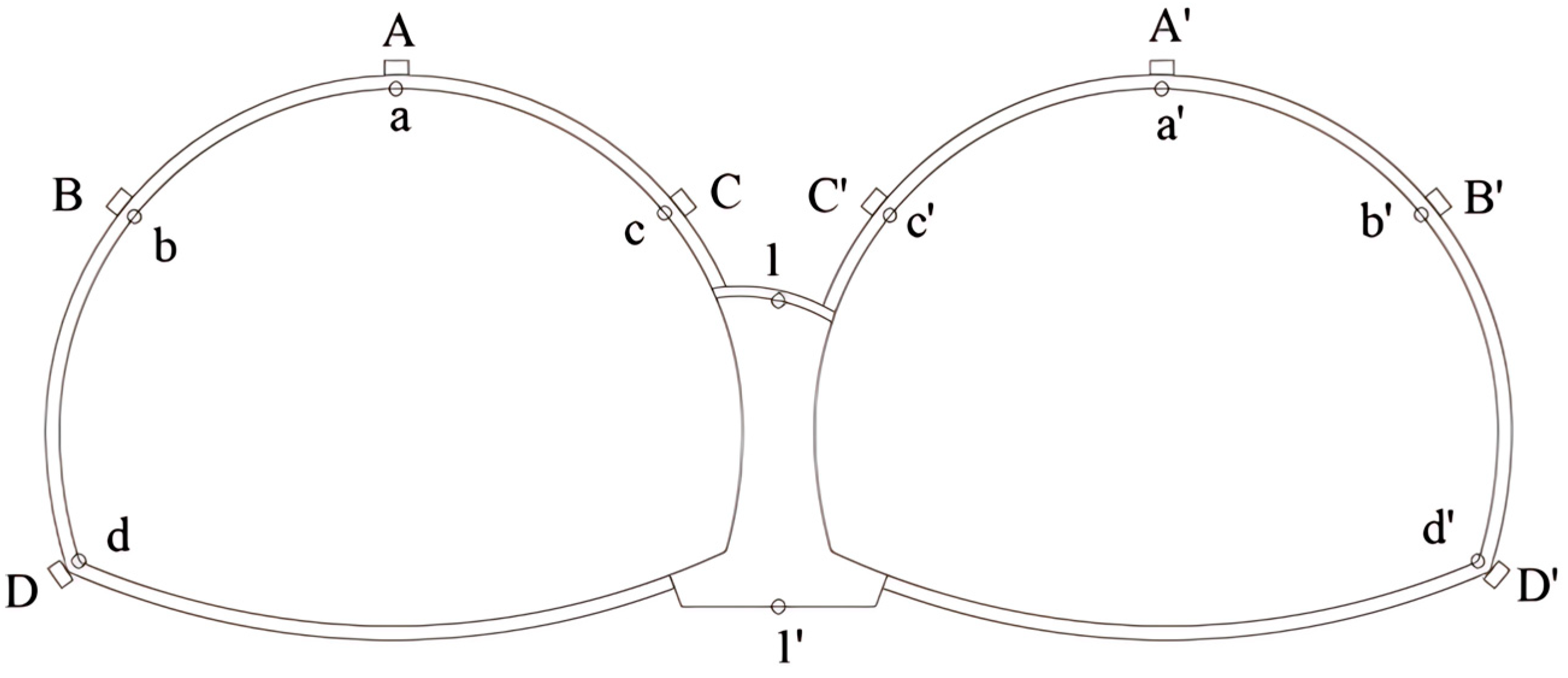
By setting up data acquisition points on the model, stress and deformation values at different locations of the surrounding rock mass and tunnel are obtained, as shown in Figure 5. In Figure 5, uppercase letters A, B, C, D, A′, B′, C′, D′ represent data acquisition points for the surrounding rock, while lowercase letters a, b, c, d, a′, b′, c′, d′ represent data acquisition points for primary support. The numbers 1 and 1′ denote data acquisition points for the middle partition wall.

3. Parametric Analysis of Joint Characteristics

3.1. Effect of Joint Dip Angle on BIAS and Deformation

We assume a joint spacing of 3.5 m and a strike of 0° in the rock mass. Eight numerical cases were established, including one intact rock mass (no joints) and seven jointed rock masses with dip angles of 0°, 15°, 30°, 45°, 60°, 75°, and 90° [56].

3.1.1. Surrounding Rock Deformation Patterns

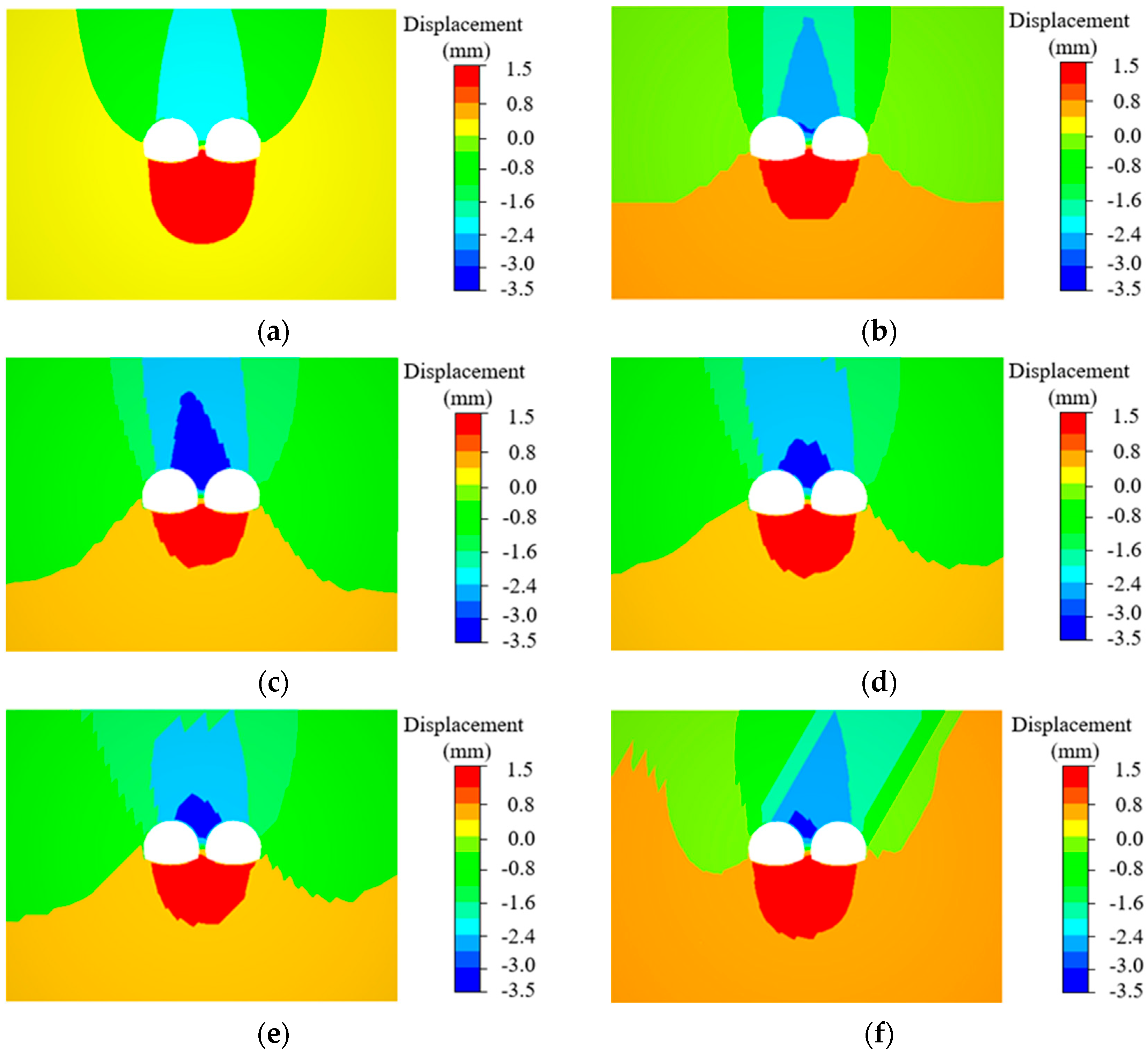
Through systematic comparison of vertical displacement distributions under varying joint dip angles, the deformation behavior of the surrounding rock mass in the double-arch tunnel was qualitatively investigated, as shown in Figure 6. The displacement sign convention defines positive/negative values as upward/downward displacements relative to the initial ground surface.
Comprehensive analysis of the displacement distribution patterns in Figure 6 yields the following conclusions: in intact rock masses (no joints), the vertical displacement of the surrounding rock exhibits a symmetrical distribution relative to the tunnel axis; in jointed rock masses, the vertical displacement directly above the tunnel remains approximately symmetrical at joint dip angles of 0° and 90°, while a pronounced bias toward the counter-dip side (left tunnel) is observed at dip angles of 15–45°, and a dominant shift toward the dip side (right tunnel) occurs at dip angles of 45–75°. This asymmetrical deformation is attributed to the BIAS field, which demonstrates a significant dependency on the joint dip angles.
Further analysis of the maximum positive and negative displacement patterns in Figure 6 demonstrates that, compared to the intact rock mass (no joints), the peak vertical displacements (both positive and negative) in jointed rock masses exhibit significant amplification, primarily due to joint-induced structural integrity degradation and consequent strength reduction of the surrounding rock. The maximum positive displacement is localized at the base of the middle partition wall, whereas the maximum negative displacement concentrates at its crown, a phenomenon driven by continuous construction-induced disturbances that progressively weaken the rock mass around the partition wall. Notably, downward displacement (negative values) poses a higher risk to construction safety. Quantitative evaluation of the maximum negative displacement evolution with joint dip angles reveals two distinct regimes: from 15° to 45°, the displacement magnitude decreases with increasing dip angle, reflecting enhanced surrounding rock stability; from 45° to 90°, the displacement magnitude increases with dip angle, indicating stability deterioration. Consequently, optimal stability is achieved at a dip angle of 45°, while the most critical instability occurs at 90°.
The calculated vertical displacements at surrounding rock crown positions (A and A′) and horizontal displacements at haunch points (B, C, B′, and C′) were systematically analyzed to quantify crown settlement and horizontal convergence magnitudes. Figure 7a (graphs plotted using OriginPro 2024, OriginLab Corporation, Northampton, MA, USA) depicts the directional deformation characteristics under varying joint dip angles, demonstrating non-linear relationships between joint dip angles (0–90°) and both crown settlement/horizontal convergence. The asymmetric deformation differential was defined as the displacement value of the left tunnel minus that of the right tunnel. Crown settlement was assigned negative values to denote a downward displacement direction.
Figure 7a demonstrates that the introduction of joints (compared to intact rock mass) triggers significant amplification in crown settlement and horizontal convergence for both left and right tunnels. This trend correlates with stress redistribution patterns captured in displacement nephograms, where joint-induced rock fragmentation and interlocking loss degrade the rock mass integrity, thereby amplifying deformation magnitudes. As the joint dip angle ascends from 0° to 45°, crown settlement and horizontal convergence exhibit progressive attenuation due to enhanced interlayer shear resistance and improved stress arching effects. Conversely, increasing dip angles from 45° to 90° reverse this trend, with deformation magnitudes escalating to peak values at 90°, consistent with the critical instability threshold identified in maximum negative displacement fields. Stability analysis confirms optimal rock mass performance at 45° dip angles versus severe instability at 90°, governed by the transition from compressive-shear to tensile-dominated failure modes. This indicates that the effect of joint dip angle variations on rock mass deformation during tunnel excavation in layered jointed rock is not influenced by the tunnel type.
Analyzing the relative magnitude of deformation in the surrounding rock on both sides of the main tunnels shown in Figure 7b, it is evident that in the absence of joints and at joint dip angles of 0° and 90°, the deformations of the left and right tunnels are nearly equal. However, under other joint dip angles, the counter-dip side rock mass deformation is greater, with the left tunnel consistently experiencing more significant deformation than the right tunnel. The asymmetrical deformation is caused by the BIAS from the surrounding rock mass. As the joint dip angle increases, the magnitude of asymmetry first increases and then decreases, with the maximum asymmetry occurring at 45°, where the BIAS peaks in magnitude.

3.1.2. Differential Displacement of Middle Partition Wall

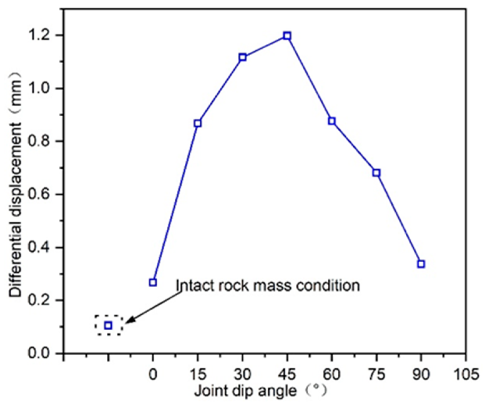
The middle partition wall constitutes a critical weak zone in double-arch tunnel systems, where its stability fundamentally governs construction safety. Following the analytical methodology of Peng et al. [57], partition wall stability was evaluated through differential displacement analysis along its vertical axis. Investigation of displacement differentials between points 1 and 1′ (crown and base positions along the partition wall axis, Figure 5) reveals two key patterns, shown in Figure 8 (graphs plotted using OriginPro 2024, OriginLab Corporation, Northampton, MA, USA): jointed conditions consistently exhibit greater displacement differentials compared to intact rock masses; displacement differentials demonstrate non-monotonic dependence on joint dip angles—initial escalation (0–45°) followed by gradual attenuation (45–90°), peaking at 45° dip angle. This progression inversely correlates with stability evolution, signifying minimum stability performance at 45°. Mechanistically, the BIAS field generates differential stress states across the twin tunnels flanking the partition wall, driving vertical displacement disparities. Consequently, the observed variation pattern of displacement differentials along the partition wall axis quantitatively reflects the biphasic evolution of BIAS—initial intensification followed by subsequent mitigation.

3.1.3. Quantification of BIAS Magnitude

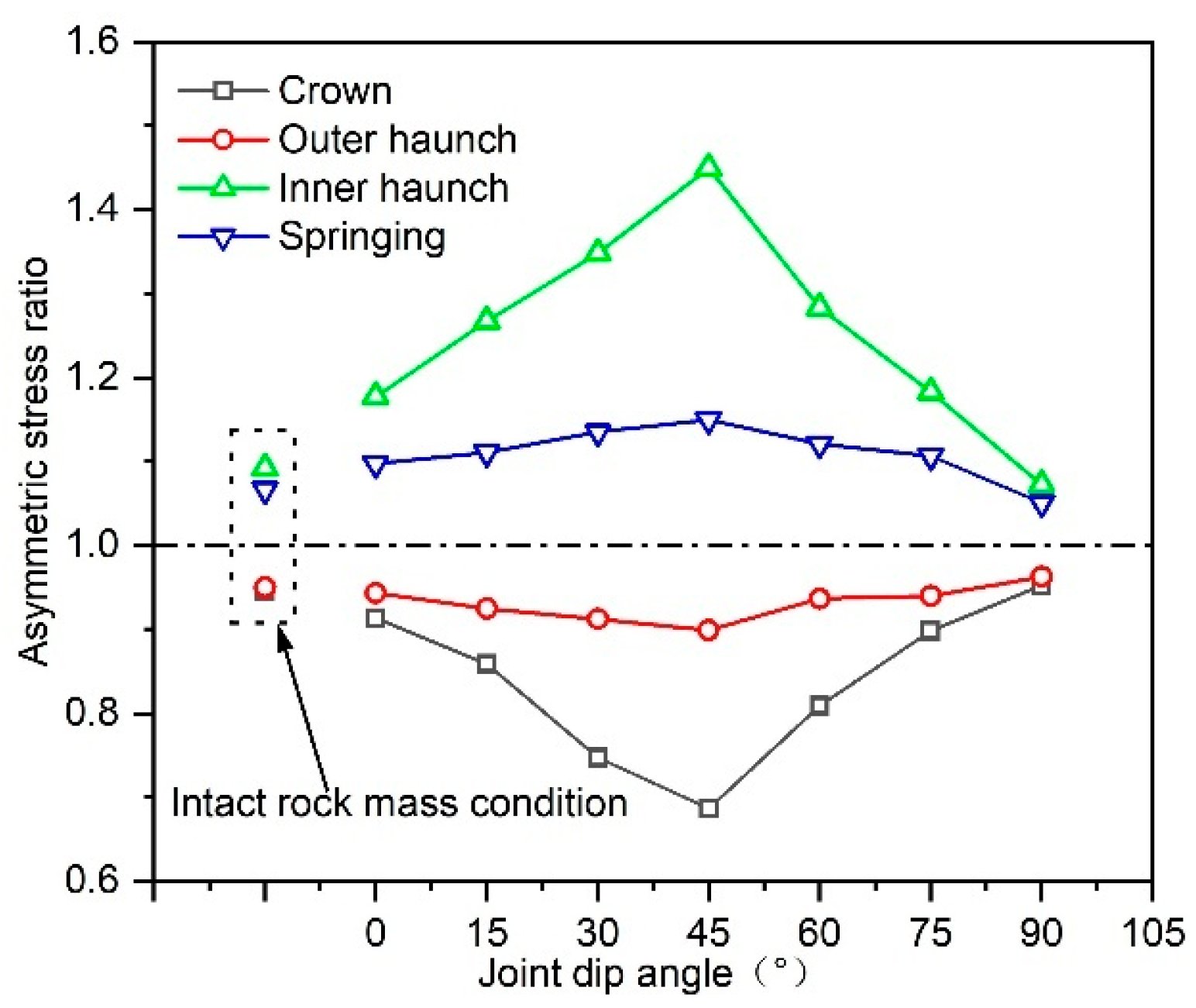
To quantitatively assess the influence of joint dip angles on asymmetric stress distributions in double-arch tunnels, the asymmetric stress ratio is defined as the stress quotient between symmetrically positioned monitoring points along the left and right tunnel peripheries at equivalent overburden depths, adopting the methodology of Yu et al. [58]. In this study, the right-to-left tunnel asymmetric stress ratios are expressed as σ A / σ A , σ B / σ B ,   σ C / σ C ,   σ D / σ D , where ratios exceeding unity indicate right tunnel stress dominance. This ratio serves as a metric for evaluating tunnel asymmetry, with values approaching 1 denoting reduced asymmetry. Figure 9 (graphs plotted using OriginPro 2024, OriginLab Corporation, Northampton, MA, USA) illustrates the evolution of asymmetric stress ratios across monitoring locations with varying joint dip angles, where outer haunch points (B, B′) and inner haunch points (C, C′) are explicitly identified. Analytical results demonstrate three consistent patterns: stress magnitudes at crown (A/A′) and outer haunch (B/B′) positions are elevated on the counter-dip side (left tunnel); springing (D/D′) and inner haunch (C/C′) regions exhibit stress concentration on the dip side (right tunnel); all monitoring points display non-monotonic asymmetric stress ratio evolution—initial escalation (0–45°) followed by attenuation (45–90°)—with peak asymmetry occurring at 45°. This inflection point corroborates the biphasic asymmetry evolution (progressive intensification then mitigation) identified in prior displacement and stability analyses, confirming the critical control of joint dip angles on stress field anisotropy.
In conclusion, through comprehensive analysis of three key aspects—surrounding rock deformation, asymmetric deformation of the middle partition wall, and the magnitude of surrounding rock asymmetric stress—the influence law of joint dip angle on BIAS in layered jointed rock masses within double-arch tunnels is established as follows: With increasing joint dip angle, the BIAS acting on the double-arch tunnel demonstrates an initial increase followed by subsequent decrease.

3.2. Effect of Joint Spacing on Rock Mass Integrity

To investigate the influence of joint spacing on BIAS effects, this study established seven numerical simulation cases with fixed joint parameters: a dip angle of 45° and a strike angle of 0°. The selected joint spacing configurations include 0.5 m, 1.5 m, 2.5 m, 3.5 m, 4.5 m, 5.5 m, and 6.5 m, resulting in seven discrete simulation conditions.

3.2.1. Effect of Joint Spacing on Surrounding Rock Deformation

The curves illustrating the variations of surrounding rock displacement and asymmetric deformation difference with joint spacing were plotted in Figure 10 (graphs plotted using OriginPro 2024, OriginLab Corporation, Northampton, MA, USA). In Figure 10, the crown settlement (negative value, directed vertically downward) and horizontal convergence of both main tunnels gradually decrease as the joint spacing increases, consistent with the evolution of maximum positive and negative displacements observed in the displacement nephograms. Due to BIAS, asymmetric deformations occur between the two main tunnels: the crown settlement and horizontal convergence of the counter-dip side (left tunnel) consistently exceed those of the dip side (right tunnel). The asymmetric deformation difference between the two tunnels diminishes with increasing joint spacing, reflecting a reduction in BIAS. This phenomenon is attributed to improved rock mass integrity and enhanced mechanical properties (e.g., strength) as joint spacing increases, causing the surrounding rock to behave more like intact rock, thereby reducing deformation.

3.2.2. Differential Displacement of Middle Partition Wall Under Different Joint Spacings

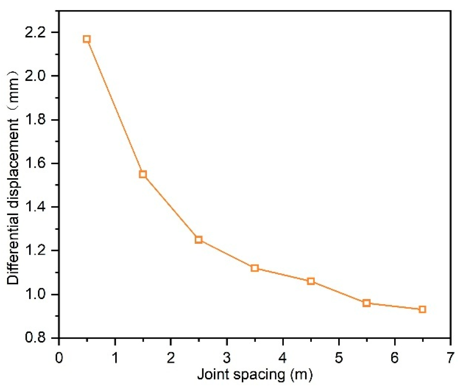
The displacement difference between points 1 and 1′ (top and bottom of the middle partition wall axis) was calculated to evaluate wall stability under varying joint spacings, as shown in Figure 11 (graphs plotted using OriginPro 2024, OriginLab Corporation, Northampton, MA, USA). The results demonstrate that the displacement difference decreases significantly with increasing joint spacing, indicating reduced BIAS and enhanced wall stability. Specifically, at a joint spacing of 6.5 m, the displacement difference exhibits a 57.1% reduction compared to that at 0.5 m, confirming the critical influence of joint spacing on wall stability. The average reduction rate of displacement difference is approximately 0.4 mm/m for spacings from 0.5 to 3.5 m, but decreases to 0.1 mm/m for spacings from 3.5 to 6.5 m. This marked decline in reduction rate suggests that once joint spacing exceeds a threshold (≈3.5 m), its impact on BIAS becomes negligible.

3.2.3. Quantification of BIAS Magnitude Under Different Joint Spacings

Figure 12 (graphs plotted using OriginPro 2024, OriginLab Corporation, Northampton, MA, USA) presents the variation curves of asymmetric stress ratios at different locations with joint spacing. An asymmetric stress ratio closer to 1 indicates lower asymmetric stress in the double-arch tunnel, while a ratio > 1 implies higher stress in the right tunnel and vice versa. Key findings include the following:
The left tunnel exhibits higher stresses at the crown and outer haunch, whereas the right tunnel experiences higher stresses at the inner haunch and springing. The asymmetric stress severity ranks as follows: crown > inner haunch > springing > outer haunch.
As joint spacing increases, asymmetric stress ratios at all locations approach 1, indicating a gradual decline in BIAS, consistent with conclusions drawn from prior analyses.
When joint spacing exceeds 3.5 m, the asymmetric stress ratios stabilize, suggesting negligible further reduction in BIAS.
In conclusion, through systematic analysis of three critical aspects—surrounding rock deformation, asymmetric deformation of the middle partition wall, and the magnitude of surrounding rock asymmetric stress—it is demonstrated that BIAS attenuates progressively with increasing joint spacing. When the spacing exceeds 3.5 m, the influence of joint spacing on BIAS becomes significantly diminished, consistent with conclusions drawn from prior parametric studies [59].

4. Analysis of Control Measures for BIAS

4.1. Optimization of Construction Methods

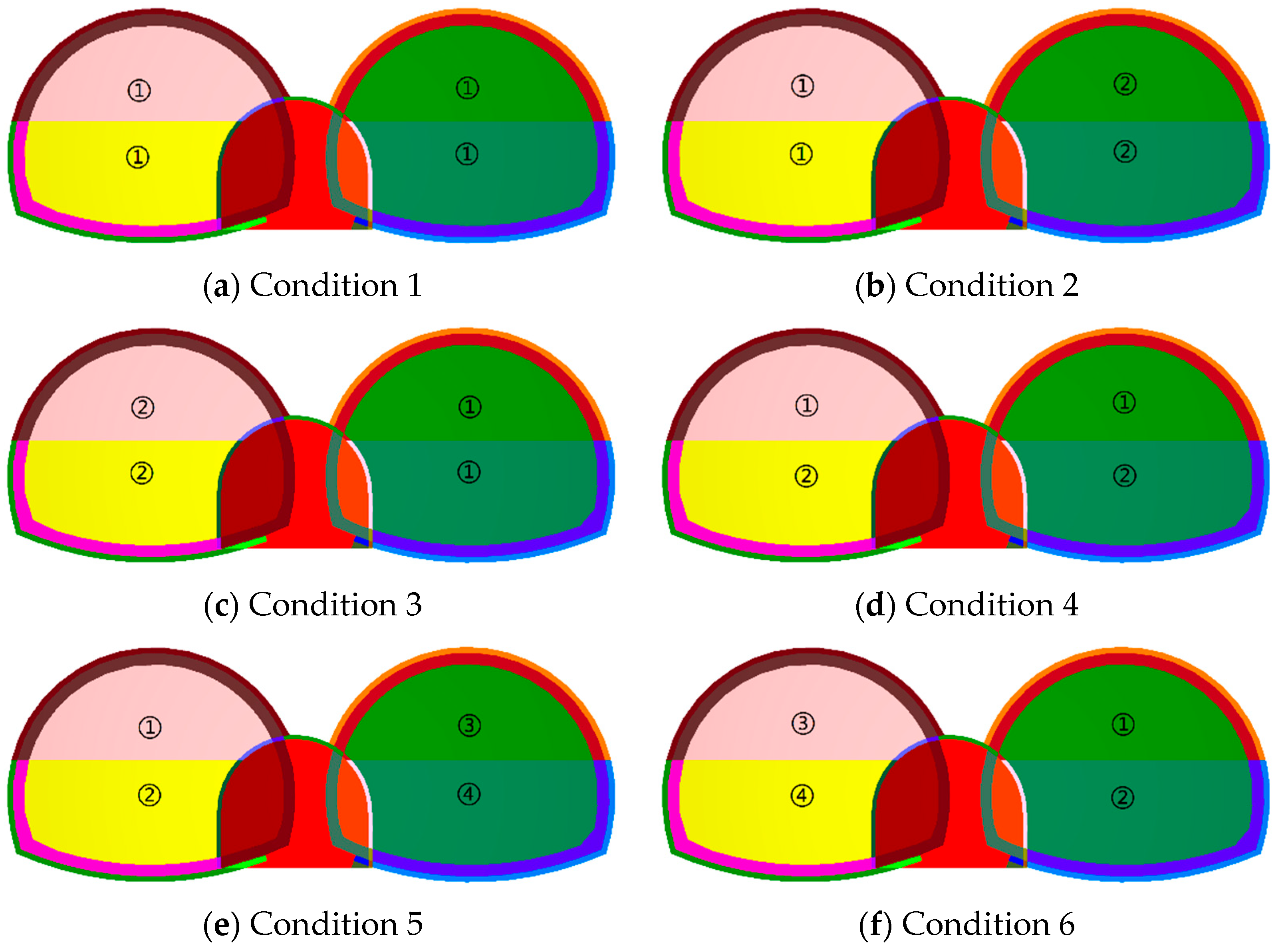
Based on the study by Wang and Zhu [60] on asymmetric stress control measures for separated tunnels under BIAS conditions, this study modified the construction methodology by varying the excavation sequence of the twin main tunnels (simultaneous excavation, left tunnel precedence, or right tunnel precedence) and the excavation methods for the main tunnels (full-face excavation method or bench method). A total of six construction conditions were established, as summarized in Table 5.
To simulate the layered jointed rock mass, the joint parameters in the model were set as follows: joint dip angle of 45°, joint spacing of 3.5 m, and joint strike angle of 0°. The specific construction procedures for the double-arch tunnel are illustrated in Figure 13. Taking condition 5 as an example, which adopts left tunnel precedence with bench method, the construction sequence comprises four stages: (1) excavation of the left tunnel upper bench; (2) excavation of the left tunnel lower bench; (3) excavation of the right tunnel upper bench; (4) excavation of the right tunnel lower bench.

4.1.1. Influence of Excavation Sequence on Surrounding Rock Deformation

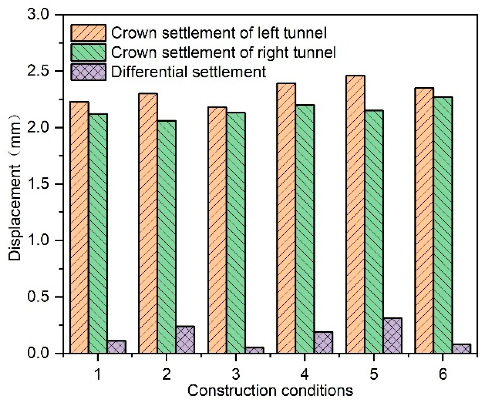
Crown settlement, significantly larger than the horizontal convergence deformation and more critical to tunnel safety, was selected as the primary evaluation index. Asymmetric deformation differences between the left and right tunnels were calculated under all construction conditions, as shown in Figure 14 (graphs plotted using OriginPro 2024, OriginLab Corporation, Northampton, MA, USA).
The analysis of Figure 14 revealed the following findings: By comparing construction conditions 1–4, 2–5, and 3–6, the surrounding rock deformation and asymmetric deformation difference during implementation of the full-face excavation method were significantly smaller than those observed with the bench method, demonstrating that the full-face excavation method induces less disturbance to surrounding rock and results in lower asymmetric stress intensity in double-arch tunnels. Through comparison of construction conditions 1–2–3 and 4–5–6, the minimum crown settlement of each main tunnel occurs when the adjacent tunnel is excavated first. Specifically, the left tunnel’s crown settlement reaches its minimum value when the right tunnel precedes excavation (conditions 3 and 6), while the right tunnel’s crown settlement minimizes when the left tunnel is excavated first (conditions 2 and 5). Furthermore, the asymmetric deformation difference achieves its minimum value when the dip side (right tunnel) is excavated first (conditions 3 and 6), indicating that prioritizing excavation of the dip side provides superior control effectiveness against BIAS in layered rock formations.

4.1.2. Stability Enhancement of the Middle Partition Wall

Figure 15 (graphs plotted using OriginPro 2024, OriginLab Corporation) illustrates the relationship between different construction conditions and the horizontal displacement difference between the top and bottom of the middle partition wall axis. As shown in Figure 15, comparative analysis of construction conditions 1–4, 2–5, and 3–6 revealed that the deformation differential of the middle partition wall axis under full-face excavation method is significantly smaller than that under the bench method, demonstrating superior stability performance of the partition wall and enhanced control effectiveness against BIAS in double-arch tunnels. The displacement differences in construction condition groups 1–2–3 follows the order condition 3 < condition 1 < condition 2, while in groups 4–5–6 the sequence becomes condition 6 < condition 4 < condition 5. This pattern confirms that prioritizing excavation of the dip side achieves optimal middle partition wall stability and minimizes asymmetric stress intensity in double-arch tunnel systems, establishing dip side precedence as the most effective construction sequence for controlling deformation in layered jointed rock masses.

4.1.3. Reduction of Asymmetric Stress Ratios

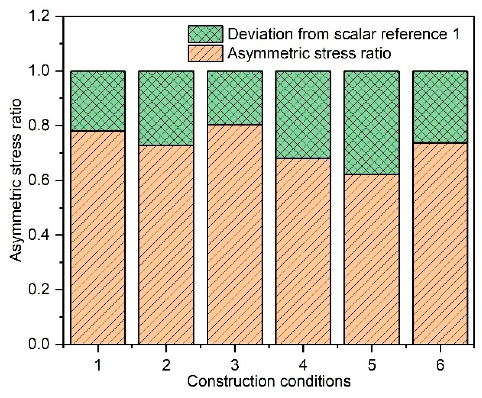
Due to the more pronounced asymmetric stress magnitude of surrounding rock at the vault across different positions, the vault asymmetric stress ratio was selected as the analytical indicator. The calculated asymmetric stress ratios and their deviations from unity under various construction conditions are presented in Figure 16 (graphs plotted using OriginPro 2024, OriginLab Corporation, Northampton, MA, USA), where smaller deviations from 1 indicate a lower magnitude of asymmetric stress.
Analysis of Figure 16 revealed that, when comparing construction conditions 1–4, 2–5, and 3–6, the full-face excavation method in the main tunnel demonstrates smaller deviations of vault asymmetric stress ratios from unity compared to the bench method, which indicates reduced asymmetric stress in the double-arch tunnel. This suggests superior control effectiveness of the full-face excavation method on BIAS. Among construction conditions 1–2–3, the deviation magnitudes follow condition 3 < condition 1 < condition 2, while in construction conditions 4–5–6 they follow condition 6 < condition 4 < condition 5. Therefore, the minimum asymmetric stress magnitude in the double-arch tunnel occurs when excavation starts from the dip side (conditions 3 and 6), which aligns with the conclusions from both simulations.
In summary, through comprehensive analysis of three critical indicators—surrounding rock deformation, asymmetric deformation of the middle partition wall, and the magnitude of surrounding rock asymmetric stress—the optimal construction method for controlling BIAS in stratified jointed double-arch tunnels was determined to be the dip side priority excavation sequence combined with the full-face excavation method in the main tunnel. This combined approach demonstrated superior performance in mitigating structural asymmetrical deformation, maintaining middle partition wall stability, and reducing vault asymmetric stress ratios, thereby achieving the most effective control of BIAS in geologically unfavorable conditions.

4.2. Optimization of Rock Bolt Configuration

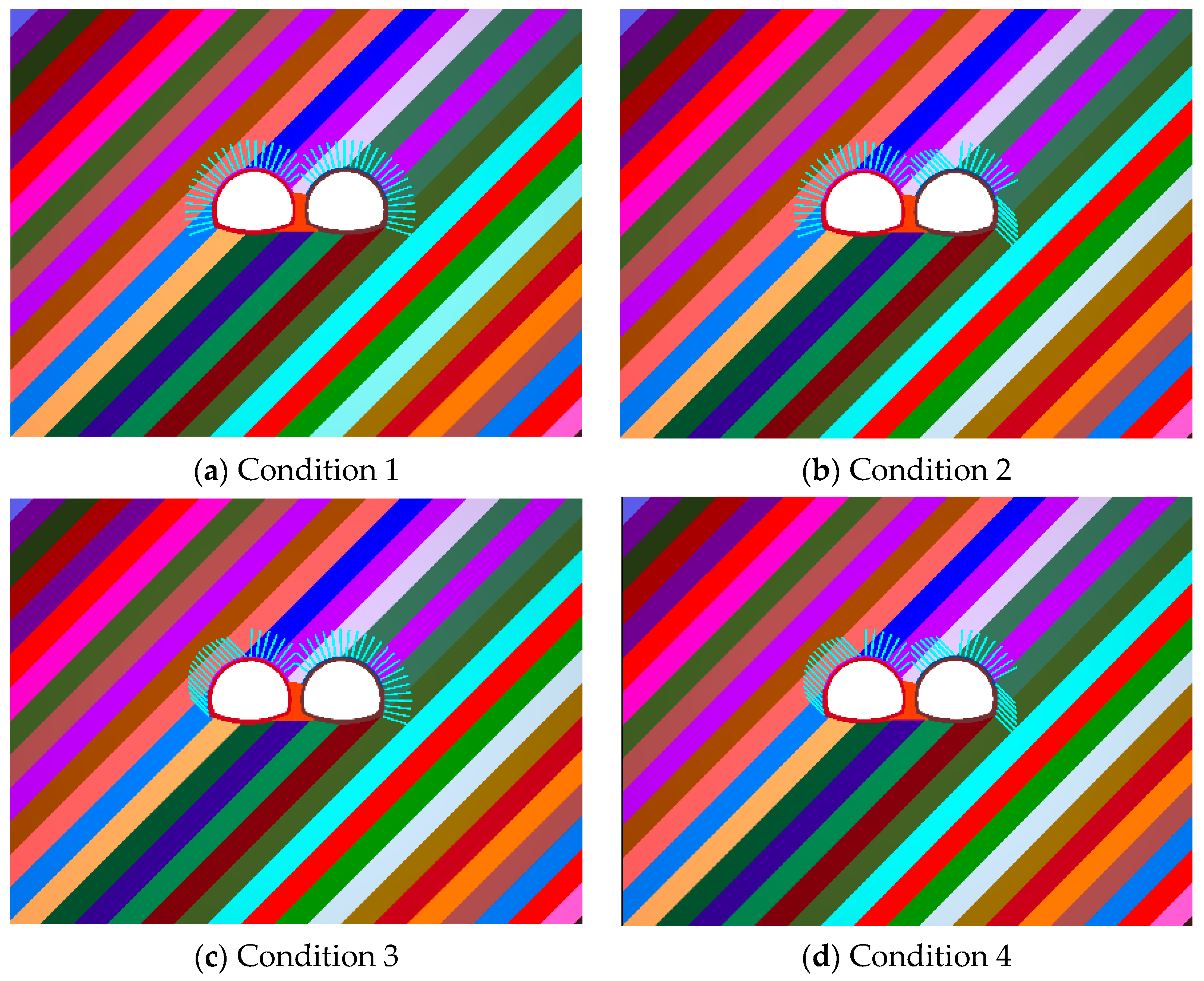
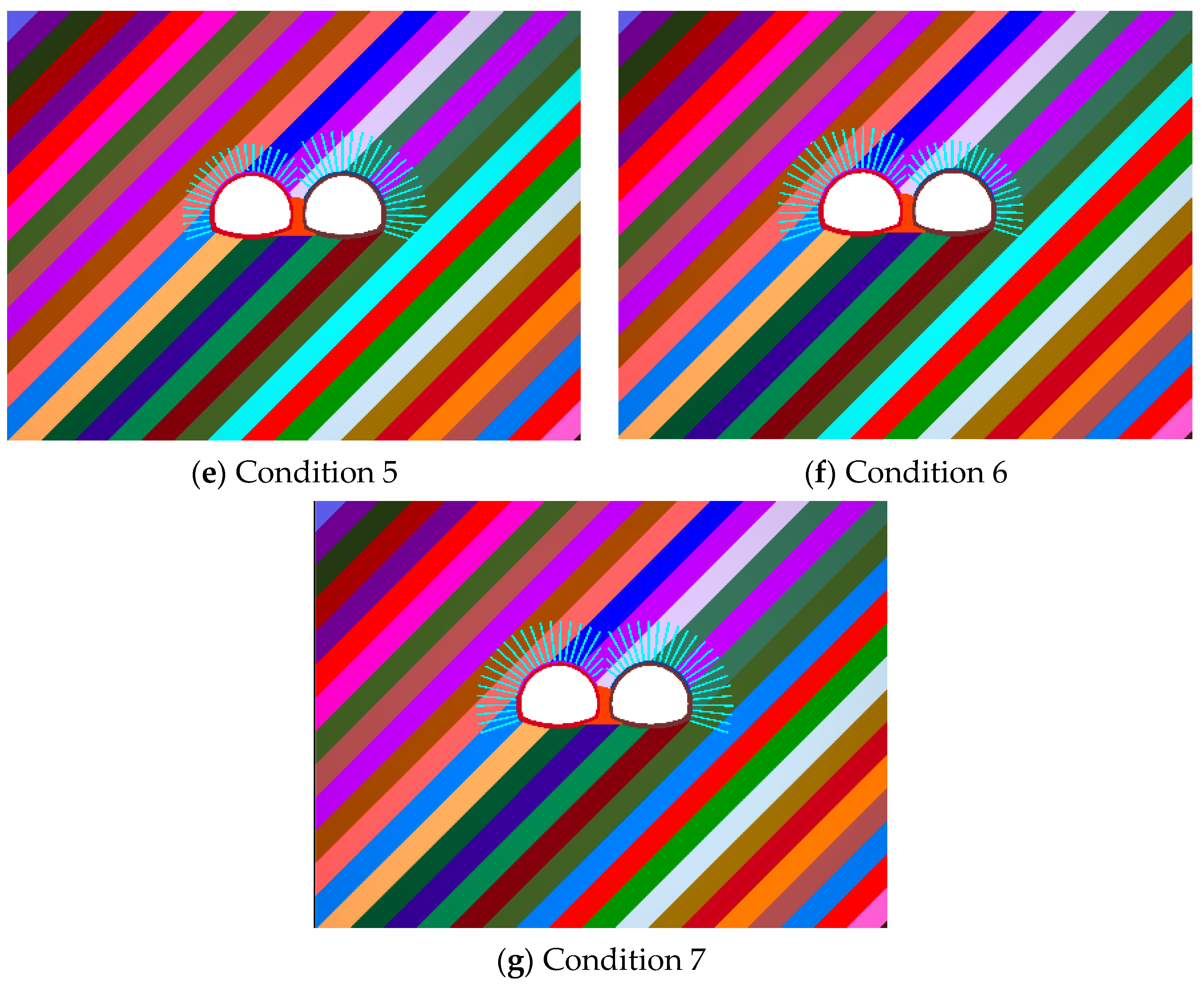
In the numerical model of the double-arch tunnel adopted for analyzing the control of BIAS effects through bolt layout under different working conditions, the joint spacing was set at 3.5 m, with a dip angle of 45° and a strike of 0°. The construction method employed was consistent with that described in Section 2.2. Drawing on references [17] concerning structural asymmetric stress control studies in layered joint separated tunnels and single-bore tunnels, this study analyzes the effects of bolt layout configurations on asymmetric stress mitigation in double-arch tunnels by adjusting bolt inclination angles and lengths. Four bolt angle configurations were designed: radial arrangement, dip side bolts perpendicular to rock strata, counter-dip side bolts perpendicular to rock strata, and fully perpendicular bolts across all rock strata. The bolt length was extended from the original 4 m to 6 m, with three configuration schemes: dip side bolt lengthening, counter-dip side bolt lengthening, and bilateral bolt lengthening, as detailed in Figure 17. During bolt layout modifications, the mechanical parameters of the bolts remained unchanged, consistent with those specified in Table 3.

4.2.1. Surrounding Rock Deformation Patterns Under Different Bolt Arrangements

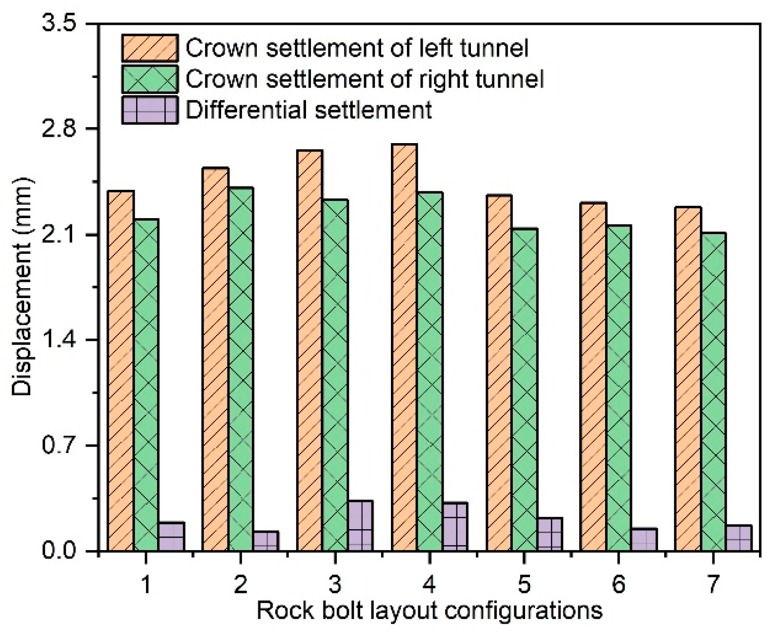
The crown settlement values of surrounding rock under various construction conditions were extracted as shown in Figure 18 (graphs plotted using OriginPro 2024, OriginLab Corporation, Northampton, MA, USA). By comparing conditions 1–2–3–4 in Figure 18 and analyzing the influence of vertical bolt configurations on crown settlement under identical bolt lengths, it is observed that cases with bolts perpendicular to rock strata (conditions 2–3–4) exhibit greater crown settlement than the fully radial arrangement (condition 1). This occurs because vertical configurations fail to fully cover the surrounding rock, leaving weak zones after bolt reinforcement, demonstrating the superiority of radial arrangements for deformation control. Reduced asymmetric deformation and lower asymmetric stress are achieved only when vertical configurations are applied to the dip side (condition 2).
A comparison between condition 1 and conditions 5–6–7 in Figure 18 reveals the impact of radial bolt length variations: extended bolts significantly reduce crown settlement in both tunnels compared to non-extended cases (condition 1), attributed to enhanced reinforcement effects. Both counter-dip side extensions (condition 6) and bilateral extensions (condition 7) yield smaller asymmetric deformation differences than non-extended cases, effectively controlling BIAS. The counter-dip side extension demonstrates superior control efficiency and economic viability, making it the preferred strategy.

4.2.2. Stability Enhancement of the Middle Partition Wall Under Different Bolt Arrangements

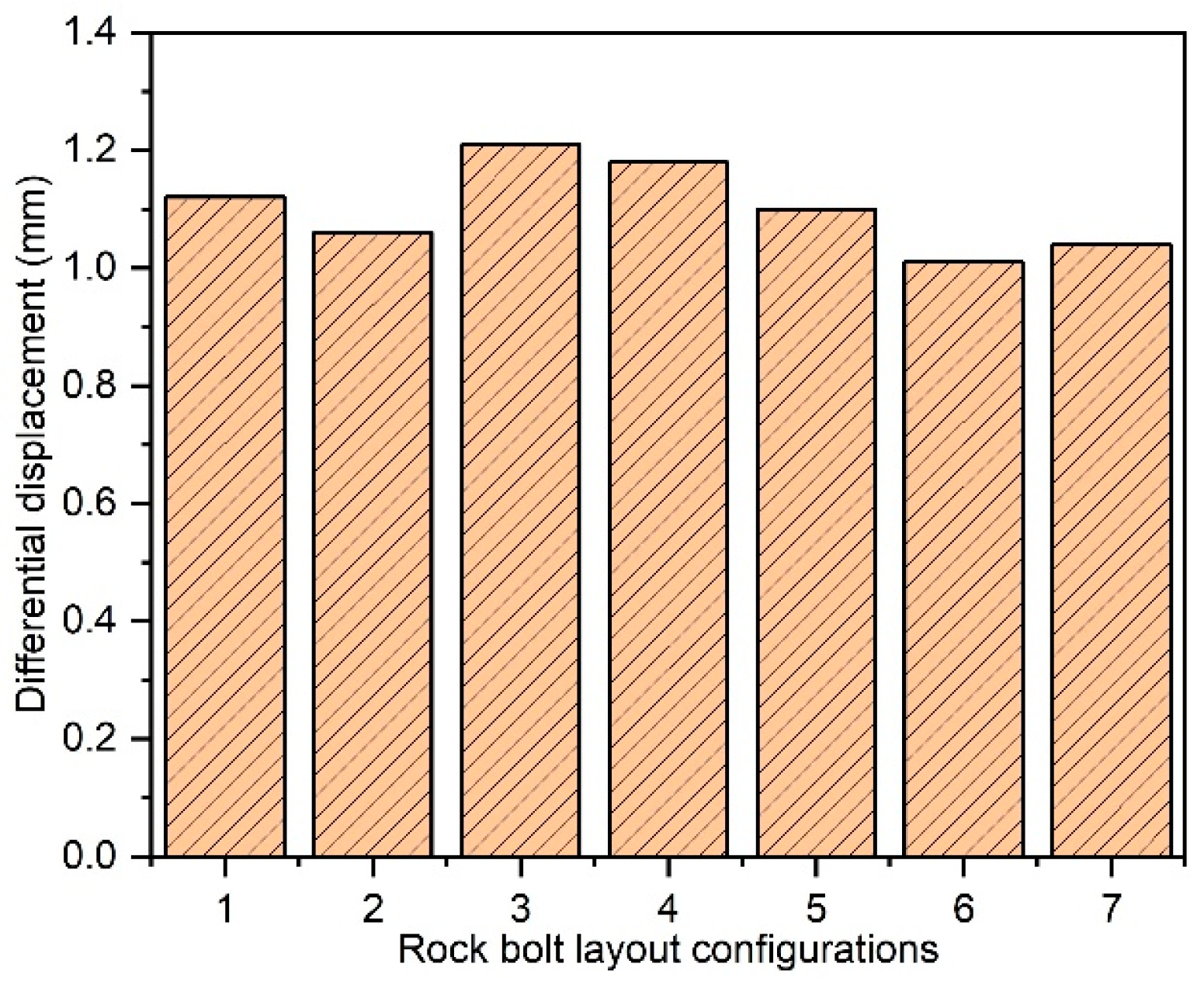
Figure 19 (graphs plotted using OriginPro 2024, OriginLab Corporation, Northampton, MA, USA) illustrates the horizontal displacement difference at the top and bottom axes of the middle partition wall under different working conditions. A comparison of conditions 1–2–3–4 in Figure 19 to analyze the effect of vertical bolt configurations on middle partition wall stability shows that dip side vertical configurations (condition 2) reduce the axial displacement difference compared to fully radial configurations (condition 1), enhancing wall stability and lowering asymmetric stress, while dip side vertical configurations (condition 3) and bilateral vertical configurations (condition 4) increase the displacement difference. Thus, dip side vertical arrangements are optimal for controlling BIAS.
Comparing condition 1 with conditions 5–6–7 in Figure 19 to evaluate bolt length variations reveals that the axial displacement differences rank as condition 6 < condition 7 < condition 5 < condition 1, demonstrating that extended bolts reduce displacement differences, improve stability, and control BIAS. Counter-dip side extensions (condition 6) achieve the minimal displacement difference, exhibiting superior control effectiveness over BIAS compared to other strategies.

4.2.3. Quantification of BIAS Magnitude Under Different Bolt Arrangements

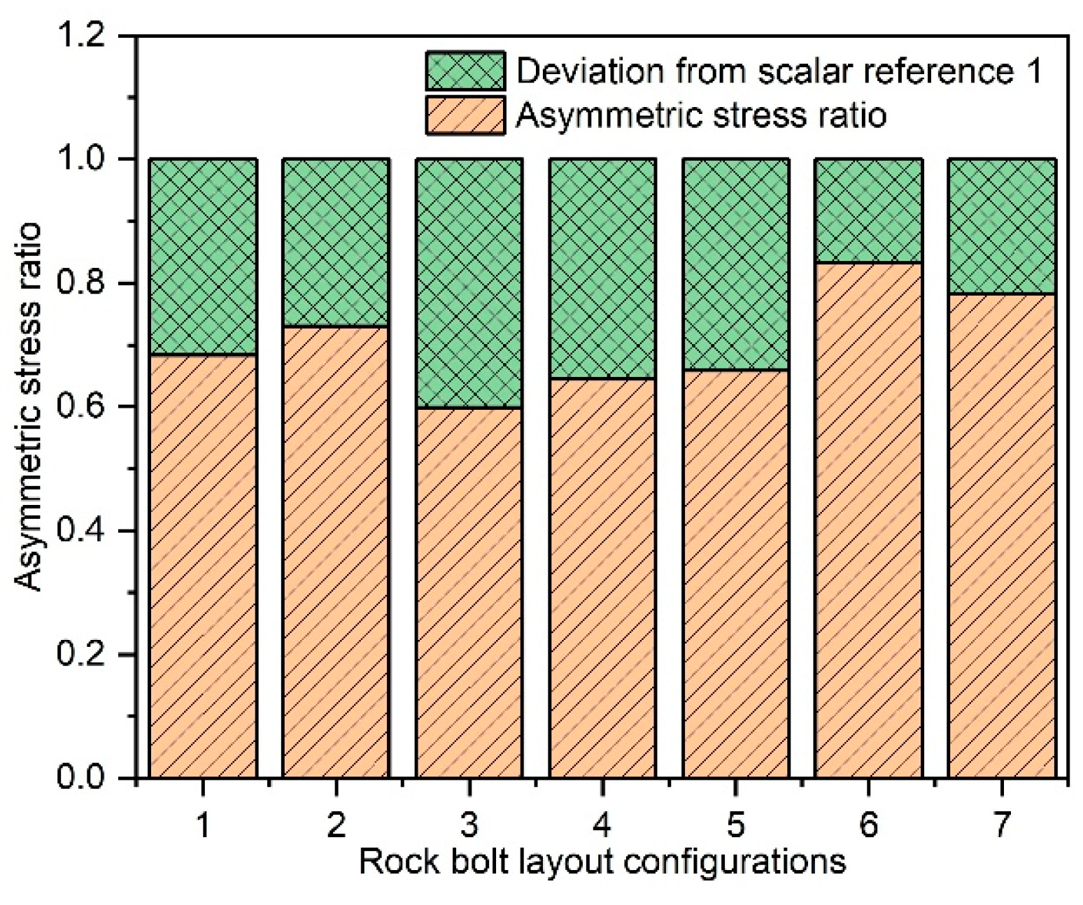
Figure 20 (graphs plotted using OriginPro 2024, OriginLab Corporation, Northampton, MA, USA) presents the asymmetric stress ratios of the surrounding rock vault under various bolt layout configurations.
Figure 20 compares conditions 1–2–3–4 to analyze the impact of vertical bolt configurations on asymmetric stress ratio in the surrounding rock. The analysis indicates that asymmetric stress ratios follow condition 3 < condition 4 < condition 1 < condition 2. Dip side bolts perpendicular to rock strata (condition 2) yield a stress ratio closest to 1, indicating minimal asymmetric stress in the double-arch tunnel. Counter-dip side (condition 3) and fully vertical configurations (condition 4) deviate further from 1 compared to fully radial arrangements (condition 1), exacerbating asymmetric stress. Thus, dip side vertical arrangements effectively control BIAS in inclined layered jointed double-arch tunnels.
A comparison of conditions 1 and 5–6–7 for bolt length variations reveals that the asymmetric stress ratios rank as condition 5 < condition 1 < condition 7 < condition 6. Dip side extensions (condition 5) increase deviation from 1, elevating tunnel asymmetric stress. Counter-dip side extensions (condition 6) and bilateral extensions (condition 7) achieve stress ratios closer to 1, with counter-dip side extensions showing superior control effectiveness. Therefore, extending counter-dip side bolt lengths is optimal for mitigating BIAS.
Through systematic analysis of surrounding rock deformation, asymmetric deformation of the middle partition wall, and the magnitude of surrounding rock asymmetric stress magnitude at the tunnel vault, the optimal rock bolt configuration strategies are determined:
(1)
Angular configuration optimization: dip side bolts perpendicular to rock strata significantly alleviate BIAS.
(2)
Length adjustment strategy: counter-dip side bolt lengthening delivers the most pronounced control effect.

5. Conclusions and Outlook

This study investigates the effects of joint dip angles and spacing on BIAS in double-arch tunnels through numerical simulations, using a Zhejiang highway tunnel as a case study. The optimization of construction methods and bolt configurations for BIAS control is systematically analyzed. Key conclusions are summarized as follows:
(1)
Deformation and stress patterns: In inclined layered jointed rock masses, the maximum downward deformation of surrounding rock occurs at the top of the middle partition wall, while the maximum upward deformation is observed at its base. Counter-dip side deformation exceeds that of the dip side, with crown settlement significantly surpassing convergence deformation. Stress concentrations are higher at the crown and outer haunch on the counter-dip side, whereas the invert and inner haunch on the dip side exhibit greater stress. The BIAS intensity at the crown and inner haunch surpasses that at other locations.
(2)
Joint parameter influences: The BIAS intensity initially increases and subsequently decreases with rising joint dip angles, reaching its peak magnitude at approximately 45°. Meanwhile, BIAS progressively diminishes as joint spacing increases, with its influence becoming negligible when spacing exceeds 3.5 m.
(3)
Optimization strategies: Construction sequencing with dip-side pilot excavation demonstrates superior BIAS control compared to other sequences. Full-face excavation outperforms the bench method in stress redistribution management. Vertical bolting (90° to bedding planes) on the dip side effectively mitigates BIAS. Lengthening counter-dip side bolts provide enhanced control compared to dip-side adjustments. These findings provide theoretical guidance and technical references for the design and construction of double-arch tunnels in layered jointed rock masses under BIAS configurations.
The limitations of this study lie in the restricted numerical analysis ranges of joint dip angles (0–90°) and spacing (0.5–6.5 m), which do not encompass extreme geological conditions (e.g., ultra-dense joints or steeply dipping reverse faults). Furthermore, the coupled effects of joint connectivity rates and intersections of multiple joint sets on BIAS remain unaddressed. Future research should prioritize the following directions:
(1)
Conducting multi-physics coupling analyses (e.g., hydro–mechanical–thermal interactions) to elucidate regulatory mechanisms of groundwater seepage and thermal gradients on BIAS evolution in stratified rock masses.
(2)
Validating current conclusions through comparative studies across diverse geological settings, particularly high-stress mountainous terrains and soft surrounding rock environments.

Author Contributions

Conceptualization, P.Z.; methodology, F.W. and P.Z.; software, F.W.; validation, L.L. and P.Z.; formal analysis, L.X. and W.L.; investigation, F.W.; resources, P.Z.; data curation, L.L. and Z.L.; writing—original draft preparation, W.L. and L.L.; writing—review and editing, P.Z., P.T. and Z.L.; visualization, L.X.; supervision, Z.L.; project administration, P.Z.; funding acquisition, P.Z., P.T and L.L. All authors have read and agreed to the published version of the manuscript.

Funding

This research was supported by the 2024 Nantong Social Livelihood Science and Technology Plan Project (MS2024032), and the Shenzhen Science and Technology Program (KCXFZ20240903094004007, GXWD20231130125225001, KQTD20210811090112003).

Data Availability Statement

The raw data supporting the conclusions of this article will be made available by the authors on request.

Conflicts of Interest

Author Pai Zhang was employed by the company Shenzhen Futian Investment Holdings Co., Ltd. Author Zaihong Li was employed by the company China United Engineering Corporation. The remaining authors declare that the research was conducted in the absence of any commercial or financial relationships that could be construed as a potential conflict of interest.

References

  1. Zhao, Y.; Li, P. A Statistical Analysis of China’s Traffic Tunnel Development Data. Engineering 2018, 4, 3–5. [Google Scholar] [CrossRef]
  2. Zhang, Z.X.; Xu, Y.; Kulatilake, P.H.S.W.; Huang, X. Physical model test and numerical analysis on the behavior of stratified rock masses during underground excavation. Int. J. Rock Mech. Min. Sci. 2011, 49, 134–147. [Google Scholar] [CrossRef]
  3. Xing, Y.; Kulatilake, P.; Sandbak, L.A. Rock Mass Stability Investigation Around Tunnels in an Underground Mine in USA. Geotech. Geol. Eng. 2017, 35, 45–67. [Google Scholar] [CrossRef]
  4. Chen, R.; Luo, Z.Y.; Zhang, L.L.; Li, Z.F.; Tan, R.Q. A new flexible-wall triaxial permeameter for localized characterizations of soil suffusion. Q. J. Eng. Geol. Hydrogeol. 2025, 58, qjegh2023-124. [Google Scholar] [CrossRef]
  5. Saroglou, C.; Qi, S.W.; Guo, S.; Wu, F. ARMR, a new classification system for the rating of anisotropic rock masses. Bull. Eng. Geol. Environ. 2019, 78, 3611–3626. [Google Scholar] [CrossRef]
  6. Hatzor, Y.H.; Feng, X.T.; Li, S.J.; Yagoda-Biran, G.; Jiang, Q.; Hu, L.X. Tunnel reinforcement in columnar jointed basalts: The role of rock mass anisotropy. Tunn. Undergr. Space Technol. 2015, 46, 1–11. [Google Scholar] [CrossRef]
  7. Exadaktylos, G.E.; Stavropoulou, M.C. A closed-form elastic solution for stresses and displacements around tunnels. Int. J. Rock Mech. Min. Sci. 2002, 39, 905–916. [Google Scholar] [CrossRef]
  8. Cui, Z.D.; Liu, D.A.; Wu, F.Q. Influence of dip directions on the main deformation region of layered rock around tunnels. Bull. Eng. Geol. Environ. 2014, 73, 441–450. [Google Scholar] [CrossRef]
  9. Mostafaei, H.; Behnamfar, F.; Alembagheri, M. Nonlinear analysis of stability of rock wedges in the abutments of an arch dam due to seismic loading. Struct. Monit. Maint. Int. J. 2020, 7, 295–317. [Google Scholar]
  10. Yao, Z.; Liu, X.; Pu, J.; Yu, T.; Fang, Y.; Yue, J.; Zhang, W. Influence of Thickness of the Partition Wall on the Bearing Capacity of Double-Arch Tunnel Under Different Buried Depth. Geotech. Geol. Eng. 2024, 42, 5891–5906. [Google Scholar] [CrossRef]
  11. Yao, S.G.; He, J.N.; Xu, P. The Change in Dynamic Response Distribution of Double-Track Tunnel Structure Caused by Adding Middle Partition Wall. Buildings 2022, 12, 1711. [Google Scholar] [CrossRef]
  12. Yang, Y.Y.; Huang, D.; Zhong, Z.; Liu, Y.; Peng, J.B. Restraint effect of partition wall on the tunnel floor heave in layered rock mass. J. Mt. Sci. 2024, 21, 2462–2479. [Google Scholar] [CrossRef]
  13. Min, B.; Zhang, X.; Zhang, C.; Gong, Y.; Yuan, T. Mechanical Behavior of Double-Arch Tunnels under the Effect of Voids on the Top of the Middle Wall. Symmetry 2018, 10, 703. [Google Scholar] [CrossRef]
  14. Wang, S.Q.; Qiao, C.S.; Xu, G.C.; Zhu, Z.G. Deformation and stress distribution of middle-wall for asymmetrically-loaded double-arch tunnel under complicated geological conditions. Rock Soil Mech. 2007, 28, 449–454. [Google Scholar]
  15. Yang, S.Q.; Li, X.L.; Zhang, W.; Fan, S.Y.; Liu, L.B. Optimization Analysis of Partition Wall Support Scheme of Multi-Arch Tunnel. Buildings 2024, 14, 490. [Google Scholar] [CrossRef]
  16. Wang, H.; Chen, R.; Leung, A.K.; Garg, A.; Jiang, Z.L. Pore-Based Modeling of Hydraulic Conductivity Function of Unsaturated Rooted Soils. Int. J. Numer. Anal. Methods Geomech. 2025, 49, 1790–1803. [Google Scholar] [CrossRef]
  17. Han, C.R.; Bai, S.W.; Wang, Y.P.; Zhang, D.H. Optimum design of rock bolts supporting long-deep tunnel in layered surrounding rock mass. Rock Soil Mech. 2016, 37, 409–414. [Google Scholar]
  18. Boon, C.W. Study of reinforcement support mechanisms for wide-span horse-shoe-shaped openings in horizontally layered jointed rock using the distinct element method. Rock Mech. Rock Eng. 2019, 52, 1179–1191. [Google Scholar] [CrossRef]
  19. Ng, C.W.W.; Liu, J.; Chen, R.; Xu, J. Physical and numerical modeling of an inclined three-layer (silt/gravelly sand/clay) capillary barrier cover system under extreme rainfall. Waste Manag. 2015, 38, 210–221. [Google Scholar] [CrossRef]
  20. Li, Z.F.; Wang, Y.H.; Li, X.; Yuan, Q. Validation of discrete element method by simulating a 2D assembly of randomly packed elliptical rods. Acta Geotech. 2017, 12, 541–557. [Google Scholar] [CrossRef]
  21. Shi, X.S.; Nie, J.; Zhao, J.; Gao, Y. A homogenization equation for the small strain stiffness of gap-graded granular materials. Comput. Geotech. 2020, 121, 103440. [Google Scholar] [CrossRef]
  22. Min, B.; Zhang, C.; Zhang, X.; Wang, H.; Li, P.; Zhang, D. Cracking performance of asymmetric double-arch tunnels due to the voids behind linings. Thin-Walled Struct. 2020, 154, 106856. [Google Scholar] [CrossRef]
  23. Li, C.L.; Wang, S.R.; Wang, Y.G.; Cui, F.; Yang, F. Skewed Pressure Characteristics of Equivalent Load in Double-Arch Tunnel. J. Eng. Technol. Sci. 2016, 48, 345–358. [Google Scholar] [CrossRef]
  24. Dancygier, A.N.; Karinski, Y.S.; Chacha, A. A model to assess the response of an arched roof of a lined tunnel. Tunn. Undergr. Space Technol. Inc. Trenchless Technol. Res. 2016, 56, 211–225. [Google Scholar] [CrossRef]
  25. Wang, F.; Ren, Q.; Yang, X.; Chen, B.; Cui, S.; Zhang, Z. Study on Dynamic Response Characteristics of Shallow-Buried and Unsymmetrical-Loaded Double-Arch Tunnel. Geotech. Geol. Eng. 2022, 41, 257–269. [Google Scholar] [CrossRef]
  26. Dang, B.; Weng, X.; Qin, C.; Chen, Y.; Hu, J. Modeling test study on influence mechanism of large-span double-arch tunnels in proximity to existing tracks. Eng. Fail. Anal. 2024, 165, 108821. [Google Scholar] [CrossRef]
  27. Wang, J.; Cao, A.; Wu, Z.; Sun, Z.; Lin, X.; Sun, L.; Liu, X.; Li, H.; Sun, Y. Numerical Simulation on the Response of Adjacent Underground Pipelines to Super Shallow Buried Large Span Double-Arch Tunnel Excavation. Appl. Sci. 2022, 12, 621. [Google Scholar] [CrossRef]
  28. Ng, C.W.W.; Liu, J.; Chen, R. Numerical Investigation on Gas Emission from Three Landfill Soil Covers under Dry Weather Conditions. Vadose Zone J. 2015, 14, vzj2014-12. [Google Scholar] [CrossRef]
  29. Ma, T.; Li, S.; Li, S.; Xu, X.; Zhang, L.; Ping, Y. Model experimental study of deformation and failure law in excavation of deep rock mass with multi-cleftiness of different angles. Rock Soil Mech. 2016, 37, 2899–2908. [Google Scholar]
  30. Wang, S.R.; Li, C.L.; Wang, Y.G.; Zou, Z.S. Evolution characteristics analysis of pressure-arch in a double-arch tunnel. Teh. Vjesn.-Tech. Gaz. 2016, 23, 181–189. [Google Scholar]
  31. Li, W.T.; He, P.; Wang, G.; Zheng, W.; Fan, K.R.; Wang, L.T.; Zheng, C.C. Elastoplastic Solution for Tunnel Composite Support Structures Based on Mohr-Coulomb Criterion. Buildings 2024, 14, 3657. [Google Scholar] [CrossRef]
  32. Sui, Y.; Cheng, X.; Wei, J. Distributed fibre optic monitoring of damaged lining in double-arch tunnel and analysis of its deformation mode. Tunn. Undergr. Space Technol. 2021, 110, 103812. [Google Scholar] [CrossRef]
  33. Li, Z.F.; Zhang, Y.F.; Chen, R.; Tai, P.; Zhang, Z.T. Numerical investigation of morphological effects on crushing characteristics of single calcareous sand particle by finite-discrete element method. Powder Technol. 2025, 453, 120592. [Google Scholar] [CrossRef]
  34. Chen, R.; Chen, Q.; Li, Z.F.; Li, Y.F.; Zhou, Y.F.; Tai, P. An integrated recycling strategy of utilising excavation waste soil in marine clay improvement. Eur. J. Environ. Civ. Eng. 2025, 1–17. [Google Scholar] [CrossRef]
  35. Niu, Q.F.; Revil, A.; Li, Z.F.; Wang, Y.H. Relationship between electrical conductivity anisotropy and fabric anisotropy in granular materials during drained triaxial compressive tests: A numerical approach. Geophys. J. Int. 2017, 210, 1–17. [Google Scholar] [CrossRef]
  36. Shi, X.S.; Zhao, J. Practical Estimation of Compression Behavior of Clayey/Silty Sands Using Equivalent Void-Ratio Concept. J. Geotech. Geoenviron. Eng. 2020, 146, 4020046. [Google Scholar] [CrossRef]
  37. Li, L.; Tian, Z.S.; Guo, X.L.; Yu, Y.; Luo, L.L. Research on large deformation of tunnels with small intervals in squeezing steeply dipping phyllite strata. Chin. J. Rock Mech. Eng. 2019, 38, 276–286. [Google Scholar]
  38. Bian, X.; Gao, Z.; Zhao, P.; Li, X. Quantitative analysis of low carbon effect of urban underground space in Xinjiekou district of Nanjing city, China. Tunn. Undergr. Space Technol. Inc. Trenchless Technol. Res. 2024, 143, 105502. [Google Scholar] [CrossRef]
  39. Yan, Q.; Zhang, C.; Lin, G.; Wang, B. Field Monitoring of Deformations and Internal Forces of Surrounding Rocks and Lining Structures in the Construction of the Gangkou Double-Arched Tunnel—A Case Study. Appl. Sci. 2017, 7, 169. [Google Scholar] [CrossRef]
  40. Sui, Y.; Cheng, X.; Zhao, Z.; Ma, W. Investigation of cracking mechanism of the first tunnel lining during double-arch tunnel construction. Undergr. Space 2024, 14, 1–17. [Google Scholar] [CrossRef]
  41. Chen, R.; Ng, C.W.W. Impact of wetting-drying cycles on hydro-mechanical behavior of an unsaturated compacted clay. Appl. Clay Sci. 2013, 86, 38–46. [Google Scholar] [CrossRef]
  42. Zhang, X.; Ye, Z.; Min, B.; Xu, Y. Effect of Voids Behind Lining on the Failure Behavior of Symmetrical Double-Arch Tunnels. Symmetry 2019, 11, 1321. [Google Scholar] [CrossRef]
  43. Wu, S.; Wu, J.; Liu, D. Research on Construction Sequences and Construction Methods of the Small Clear-Distance, Double-Arch Tunnel under an Asymmetrical Load. Appl. Sci. 2023, 13, 8242. [Google Scholar] [CrossRef]
  44. Hu, Y.; Lu, J.Y.; Zhu, J.; Zhang, H.X.; Ren, Y.; Wu, J.L.; Lai, J.B.; Zhang, H.; Zhao, H.Y.; Zeng, X. Data-knowledge hybrid driven intelligent prediction method of tunnel excavation profiles geometric deformation. Int. J. Digit. Earth 2025, 18, 2459317. [Google Scholar] [CrossRef]
  45. Hu, Z.H.; Wu, B.B.; Xu, N.W.; Wang, K. Effects of discontinuities on stress redistribution and rock failure: A case of underground caverns. Tunn. Undergr. Space Technol. 2022, 127, 104583. [Google Scholar] [CrossRef]
  46. Li, Z.F.; Wang, Y.H.; Chow, J.K. Density Effect and Associated Unjamming Events on the Aging-Induced Stiffness Increase in Sand. Int. J. Geomech. 2018, 18, 4018173. [Google Scholar] [CrossRef]
  47. Bian, X.; Fan, Z.; Liu, J.; Li, X.; Zhao, P. Regional 3D geological modeling along metro lines based on stacking ensemble model. Undergr. Space 2024, 18, 65–82. [Google Scholar] [CrossRef]
  48. Tsesarsky, M. Deformation mechanisms and stability analysis of undermined sedimentary rocks in the shallow subsurface. Eng. Geol. 2012, 133, 16–29. [Google Scholar] [CrossRef]
  49. Oğuzhan, Ç. Nonlinear Constitutive Soil Models for the Soil–Structure Interaction Modeling Issues with Emphasis on Shallow Tunnels: A Review. Arab. J. Sci. Eng. 2023, 48, 12657–12691. [Google Scholar]
  50. Liu, B.; He, K.; Han, M.; Hu, X.; Wu, T.; Wu, M.; Ma, G. Dynamic process simulation of the Xiaogangjian rockslide occurred in shattered mountain based on 3DEC and DFN. Comput. Geotech. 2021, 134, 104122. [Google Scholar] [CrossRef]
  51. He, X.; Li, Y. Analysis of stress disturbed zone of tunnel and its influence factors. J. Railw. Sci. Eng. 2019, 16, 2782–2790. [Google Scholar]
  52. Li, Z.F.; Chow, J.K.; Li, J.H.; Tai, P.; Zhou, Z.S. Modeling of flexible membrane boundary using discrete element method for drained/undrained triaxial test. Comput. Geotech. 2022, 145, 104687. [Google Scholar] [CrossRef]
  53. Li, Z.; Wang, Y.H.; Ma, C.H.; Mok, C.M.B. Experimental characterization and 3D DEM simulation of bond breakages in artificially cemented sands with different bond strengths when subjected to triaxial shearing. Acta Geotech. 2017, 12, 987–1002. [Google Scholar] [CrossRef]
  54. Zhao, J.P.; Wang, X.Y.; Tan, Z.S.; Zhang, C.; Wang, Z.X. Study on the reasonable construction layout of main tunnel in unsymmetrical loading multi-arch tunnel with weak rock. China Civ. Eng. J. 2017, 50, 66–74. [Google Scholar]
  55. JTG3370.1-2018; Code for Design of Road Tunnel Section 1 Civil Engineering. China Communications Press: Beijing, China, 2019.
  56. Manquehual, C.J.; Li, C.C.; Shabanimashcool, M.; Grindheim, B.; Lia, L. 3D Numerical Modeling of Rock Mass Failure in an Uplift Test of a Rock Anchor with Focus on the Role of Rock Joints. Rock Mech. Rock Eng. 2025, 58, 2847–2875. [Google Scholar] [CrossRef]
  57. Peng Dingchao, Y.Y.; Zhang, Y. Spatial Analysis of the Influence of Excavation Construction Methods on the Central Wall of Multi-Arch Tunnels. Mod. Tunn. Technol. 2002, 1, 47–53. [Google Scholar]
  58. Yu, Q.; Liu, W.; Nie, L.; Dai, S. Characteristic Analysis on Stress Ratio of Unsymmetrical Load Tunnel. J. Jilin Univ. (Earth Sci. Ed.) 2018, 48, 1797–1803. [Google Scholar]
  59. He, C.; Feng, J.; Jiang, N.; Zhang, Y.; Huang, L. Analysis on the Influence of Rock Joint Characteristics on Failure Mode and Stability of Bedding Tunnel. Chin. J. Undergr. Space Eng. 2020, 16, 599–607. [Google Scholar]
  60. Wang, W.; Zhu, W. Stability Analysis of Tunnels in Jointed Rock Masses. Mod. Tunn. Nnelling Technol. 2014, 51, 66–72. [Google Scholar]
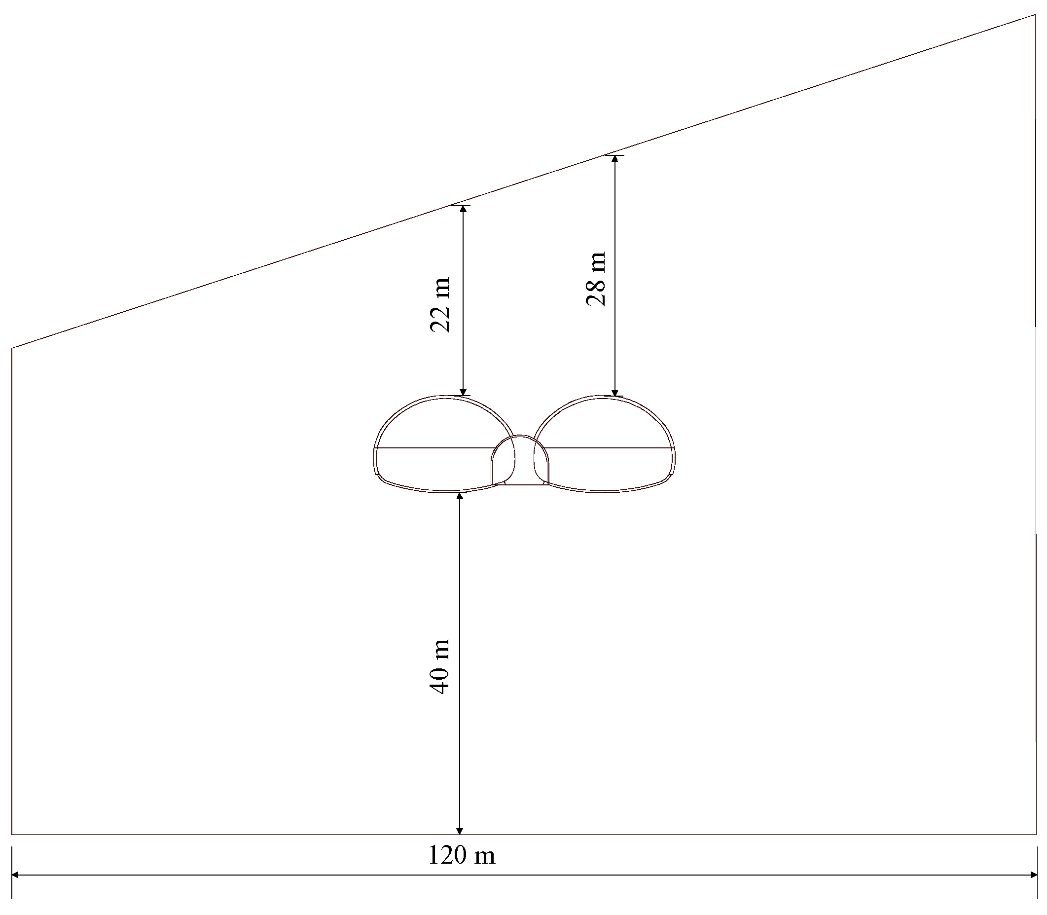
Figure 1. Schematic diagram of tunnel cross-section at chainage K1 + 650.
Buildings 15 01816 g001
Figure 2. Vertical displacement contour of cross-section at chainage K1 + 650.
Buildings 15 01816 g002
Figure 3. Crown settlement curve: (a) measured curve [54]; (b) simulated curve.
Buildings 15 01816 g003
Figure 4. Three-dimensional numerical modeling schematic.
Buildings 15 01816 g004
Figure 5. Distribution of data acquisition points in the tunnel numerical model.
Buildings 15 01816 g005
Figure 6. Vertical displacement field of surrounding rock mass at different joint dip angles: (a) intact rock mass; (b) at an angle of 0°; (c) at an angle of 15°; (d) at an angle of 30°; (e) at an angle of 45°; (f) at an angle of 60°; (g) at an angle of 75°; (h) at an angle of 90°.
Buildings 15 01816 g006aBuildings 15 01816 g006b
Figure 7. Relationship between joint dip angle and deformation of surrounding rock mass: (a) displacement variation at typical points; (b) asymmetric deformation difference.
Buildings 15 01816 g007
Figure 8. The relationship curve between joint dip angle and horizontal displacement of middle partition wall.
Buildings 15 01816 g008
Figure 9. Relationship between joint dip angle and asymmetric stress ratio.
Buildings 15 01816 g009
Figure 10. Relationship between joint spacing and deformation of surrounding rock mass: (a) displacement variation at typical points; (b) asymmetric deformation difference.
Buildings 15 01816 g010
Figure 11. The relationship curve between joint spacing and horizontal displacement of middle partition wall.
Buildings 15 01816 g011
Figure 12. Relationship between joint spacing and asymmetric stress ratio.
Buildings 15 01816 g012
Figure 13. Schematic diagram of construction conditions.
Buildings 15 01816 g013
Figure 14. Correlation between construction conditions and surrounding rock deformation.
Buildings 15 01816 g014
Figure 15. Differential displacement of middle partition wall under different construction conditions.
Buildings 15 01816 g015
Figure 16. Asymmetric stress ratio at tunnel crown under different construction configurations.
Buildings 15 01816 g016
Figure 17. Bolt configuration schematic under different construction conditions: (a) radial arrangement; (b) dip side bolts perpendicular to rock strata; (c) counter-dip side bolts perpendicular to rock strata; (d) fully perpendicular bolts across all rock strata; (e) dip side bolt lengthening; (f) counter-dip side bolt lengthening; (g) bilateral bolt lengthening.
Buildings 15 01816 g017aBuildings 15 01816 g017b
Figure 18. Correlation between bolt layout configurations and surrounding rock deformation.
Buildings 15 01816 g018
Figure 19. Differential displacement of middle partition wall under different bolt layout configurations.
Buildings 15 01816 g019
Figure 20. Asymmetric stress ratio at tunnel crown under different bolt layout configurations.
Buildings 15 01816 g020
Table 1. Physical and mechanical parameters of surrounding rock and support structures in the case study.
Material Type Unit   Weight   γ
(kN/m3)
Elastic   Modulus   E
(GPa)
Poisson s   Ratio   μ Internal   Friction   Angle   ψ
(°)
Cohesion   c
(GPa)
Rock Mass20.01.20.35250.2
Primary Support23.027.20.25
Middle Partition Wall25.032.50.20
Table 2. Comparison between measured and simulated values.
Settlement ParameterMeasured Value (mm)Simulated Value (mm)Difference (mm)Error
Left Tunnel Crown Settlement18.717.21.58.0%
Right Tunnel Crown Settlement17.616.01.69.1%
Table 3. Physical and mechanical parameters of surrounding rock mass and supporting structures.
Material Type Unit   Weight   γ
(kN/m3)
Elastic   Modulus   E
(GPa)
Poisson s   Ratio   μ Internal   Friction   Angle   ψ
(°)
Cohesion   c
(MPa)
Rock Mass24.013.00.35451.1
Primary Support24.930.50.20
Middle Partition Wall25.031.50.20
Secondary Lining25.031.50.20
Rock Bolt7.8200.00.31
Table 4. Mechanical parameters of joints.
Normal Stiffness
(GPa)
Tangential Stiffness
(GPa)
Tensile Stiffness
(kPa)
Cohesion
(kPa)
Internal Friction Angle
(°)
7.55.06.060.025.0
Table 5. Different construction conditions.
Condition 1Condition 2Condition 3Condition 4Condition 5Condition 6
Simultaneous Excavation Left Tunnel PrecedenceRight Tunnel PrecedenceSimultaneous AdvancementLeft Tunnel PrecedenceRight Tunnel Precedence
Full-face Excavation Method Full-face Excavation MethodFull-face Excavation MethodBench
Method
Bench
Method
Bench
Method
Disclaimer/Publisher’s Note: The statements, opinions and data contained in all publications are solely those of the individual author(s) and contributor(s) and not of MDPI and/or the editor(s). MDPI and/or the editor(s) disclaim responsibility for any injury to people or property resulting from any ideas, methods, instructions or products referred to in the content.