
Overturning and Reinforcement of Single-Column Pier Curved Girder Bridge Considering the Secondary Effect of Overturning


Abstract
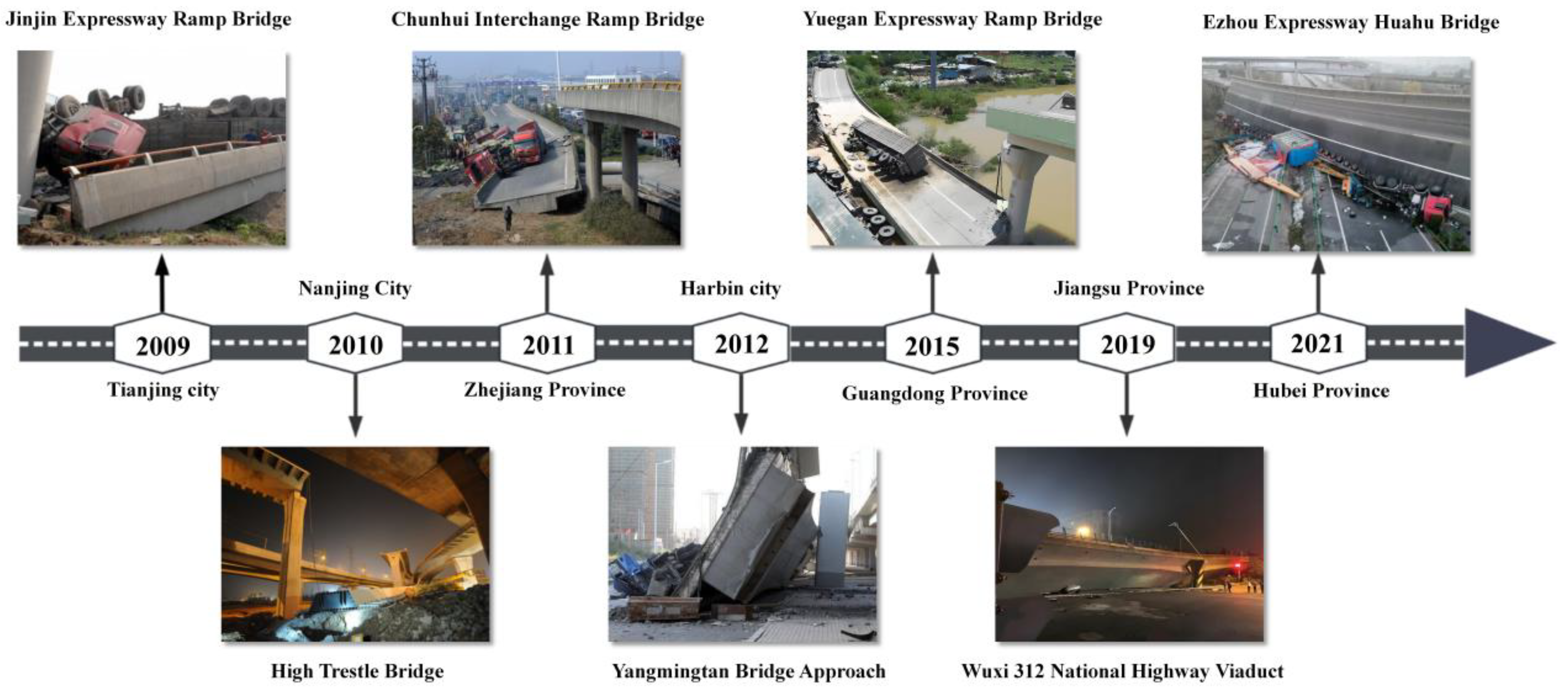
1. Introduction
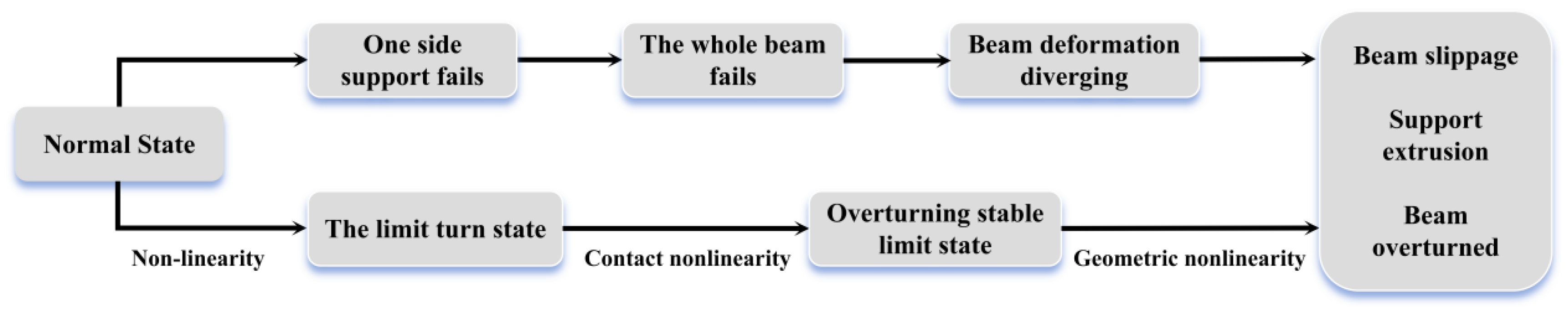
2. Overturning Mechanism of Single-Column Pier Curved
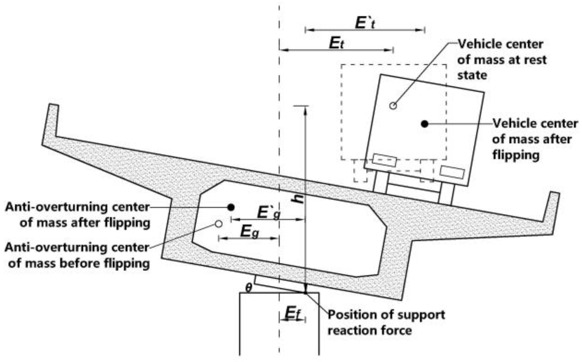
2.1. Overturning Principle
2.2. Calculation of Anti-Overturning Stability Coefficient Considering the Secondary
3. Simulation of Bridge Overturning Process
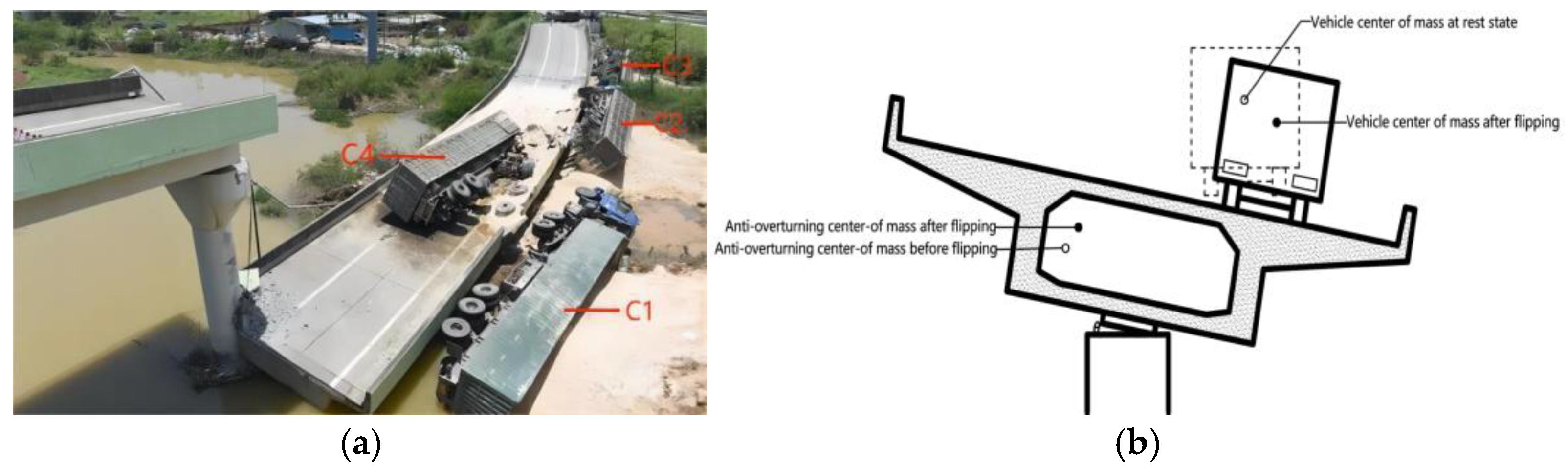
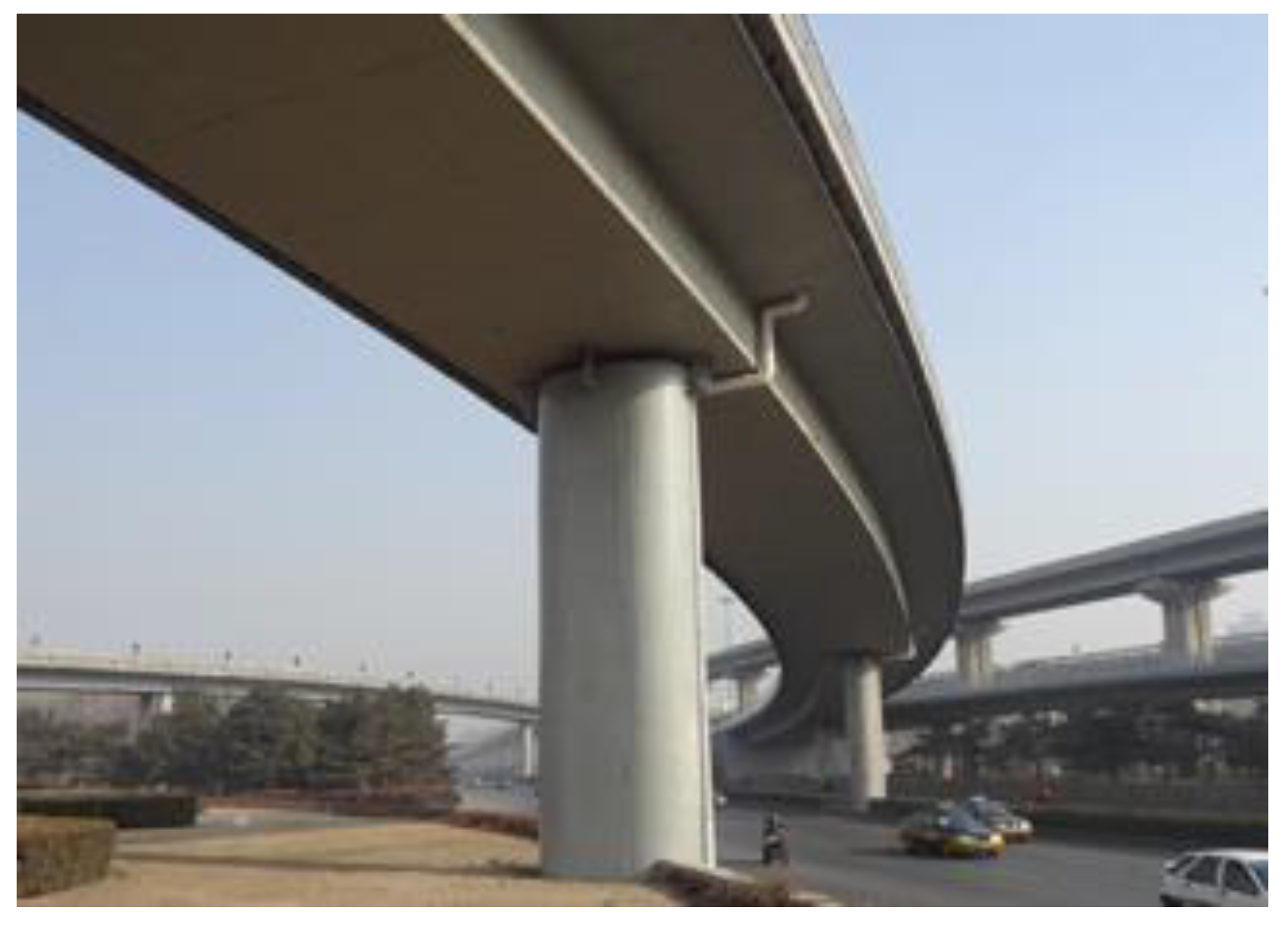
3.1. Project Overview
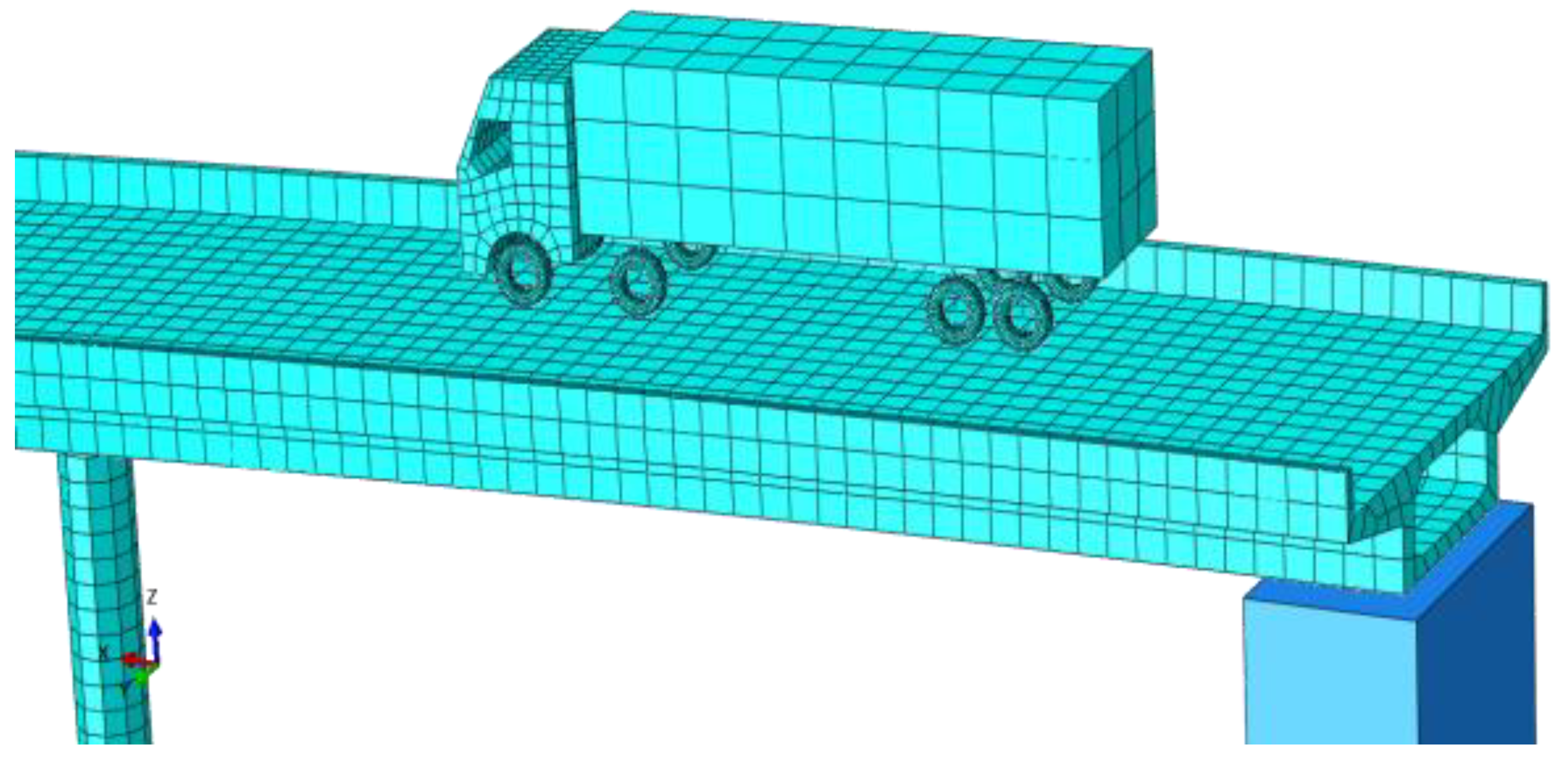
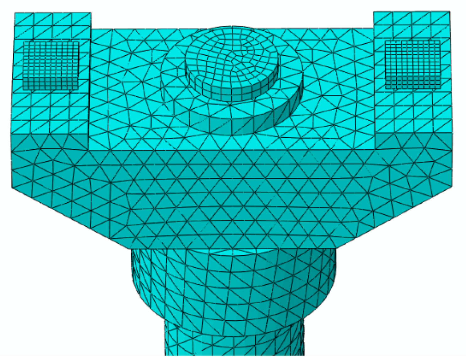
3.2. Establish Vehicle–Bridge Interaction Model
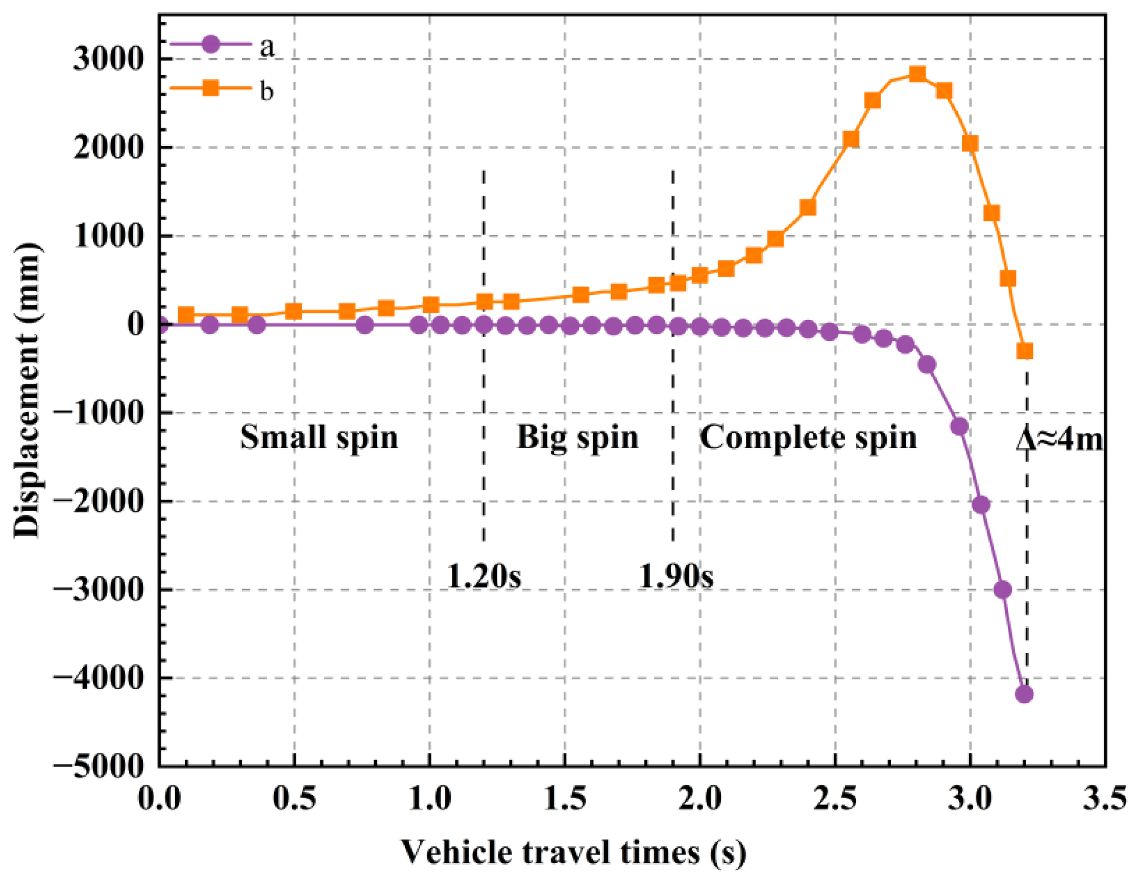
3.3. Bridge Overturning Process Analysis
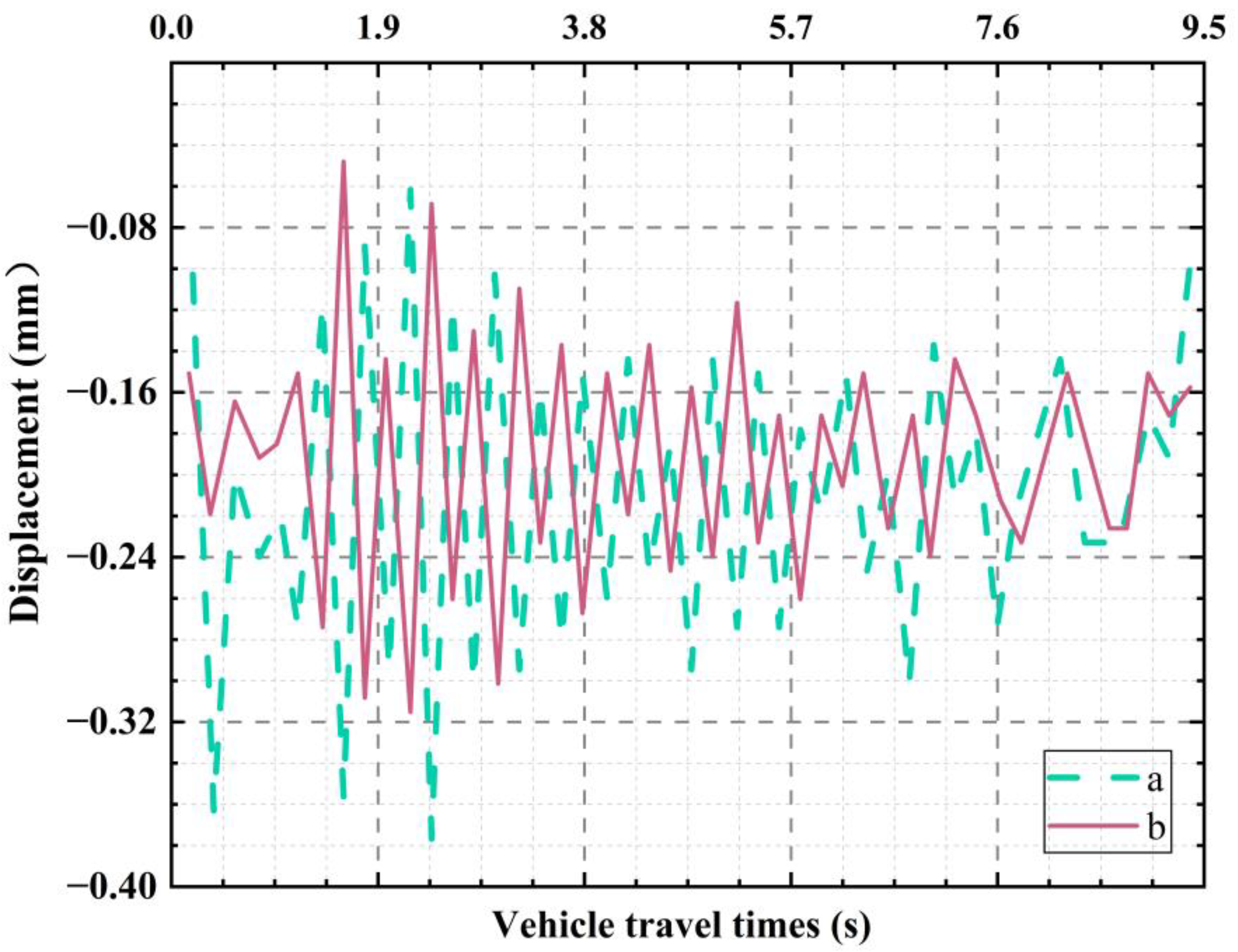
3.4. The Relative Vertical Displacement of the Main Beam During the Overturning Process
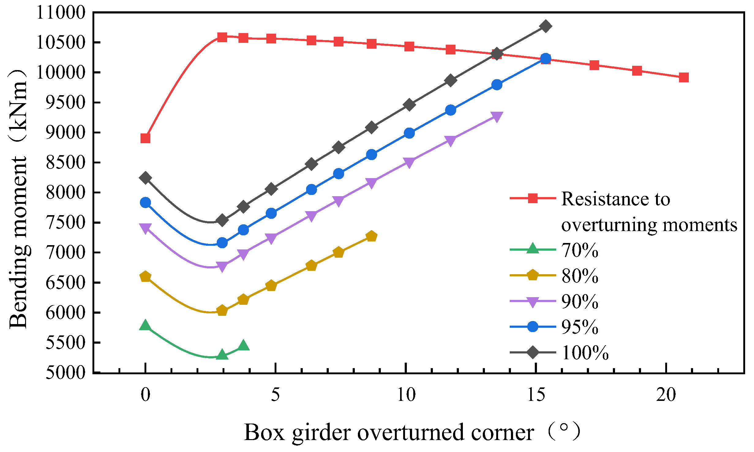
3.5. Comparison of Calculation Methods for Anti-Overturning Stability
4. Reinforcement Scheme Design
4.1. Reinforcement and Retrofit Principles
- (1)
- Reinforcement can significantly improve the overturning resistance of single-column pier bridges, and the overturning resistance after reinforcement and transformation meets the requirements of current specifications.
- (2)
- The reinforcement and transformation do not significantly change the stress system of the bridge structure, and minimize the impact on the existing components.
- (3)
- The reinforced bridge fulfills original functional requirements, such as clearance under the bridge and transportation, and minimizes traffic disruption.
- (4)
- Considering the spatial layout of the bridge and its surrounding environment, the transformed appearance accommodates the local surroundings.
4.2. Selection of Reinforcement Program
4.2.1. Pier and Beam Consolidation
4.2.2. Additional Cover Beams
4.2.3. Widening of Piers
4.2.4. Additional Setting of the Restraints Against Pull-Outs
4.2.5. Comparison and Selection of Reinforcement Schemes
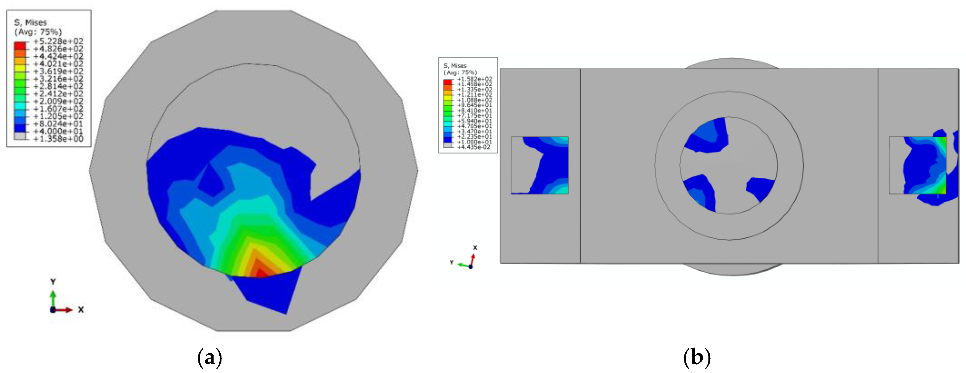
4.3. Numerical Simulation Results and Analysis
4.4. Reinforcement Pier Column Modeling
5. Reinforcement and Retrofit Evaluation
6. Conclusions
- (1)
- The finite element analysis indicates that the eccentric driving of overloaded vehicles is a primary cause of overturning in single-column pier bridges. The simulation accurately captured the structural-mechanical behavior from the onset of support deflation to complete overturning, establishing both the rotational limit state and the overturning stability limit state. The calculated results closely matched the observed overturning inclination of the ramp bridge.
- (2)
- The analysis revealed that the secondary effect of overturning, caused by the rotation of the main beam, is a critical factor in the stability of the bridge. This effect, influenced by changes in support size and moment arm during rotation, significantly impacts the overturning stability coefficient. Therefore, it is crucial to limit the maximum rotation angle of the main beam and consider the dimensions of the support during the design and reinforcement of bridges to mitigate this secondary effect and enhance stability.
- (3)
- To improve lateral stability in single-column pier curved bridges with insufficient overturning resistance, reinforcement should target the overturning force mechanism. Effective strategies include strengthening piers and girders, adding cover beams, widening piers, and installing additional restraints against pull-out. The design of these reinforcements must consider the specific location and traffic requirements of the bridge.
- (4)
- The addition of cover beams increased the overturning stability coefficient of the original bridge from 0.948 to 2.626, reducing the load on the central pier support and optimizing the overall bridge support system. This study demonstrates that the proposed reinforcement method is effective in improving the overturning stability of curved girder bridges with single-column piers. The analysis and proposed reinforcement scheme offer significant practical value for addressing lateral stability and safety issues in such bridges.
Author Contributions
Funding
Data Availability Statement
Conflicts of Interest
References
- Xu, H.; Li, Q.Y.; Li, D.C.; Jiang, H.N.; Wang, T.; Gao, Q.F. Experimental and Numerical Investigation of the Anti-Overturning Theory of Single-Column Pier Bridges. Sustainability 2023, 15, 1545. [Google Scholar] [CrossRef]
- Xiong, W.; Cai, C.S.; Kong, B.; Ye, J.S. Overturning-Collapse Modeling and Safety Assessment for Bridges Supported by Single-Column Piers. J. Bridge Eng. 2017, 22, 04017084. [Google Scholar] [CrossRef]
- Shi, X.F.; Zhou, Z.J.; Ruan, X. Failure Analysis of a Girder Bridge Collapse under Eccentric Heavy Vehicles. J. Bridge Eng. 2016, 21, 05016009. [Google Scholar] [CrossRef]
- Deng, L.; Wang, W.; Yu, Y. State-of-the-Art Review on the Causes and Mechanisms of Bridge Collapse. J. Perform. Constr. Facil. 2016, 30, 04015005. [Google Scholar] [CrossRef]
- Wardhana, K.; Hadipriono, F.C. Analysis of Recent Bridge Failures in the United States. J. Perform. Constr. Facil. 2003, 17, 144–150. [Google Scholar] [CrossRef]
- Huber, T.; Kollegger, J.; Suza, D.; Huber, P. The Wieselburg Bridge collapse—Analysis of the shear capacity based on forensic data. Struct. Concr. 2024, 25, 2784–2799. [Google Scholar] [CrossRef]
- Scattarreggia, N.; Salomone, R.; Moratti, M.; Malomo, D.; Pinho, R.; Calvi, G.M. Collapse analysis of the multi-span reinforced concrete arch bridge of Caprigliola, Italy. Eng. Struct. 2022, 251, 113375. [Google Scholar] [CrossRef]
- Schaap, H.S.; Caner, A. Bridge collapses in Turkey: Causes and remedies. Struct. Infrastruct. Eng. 2022, 18, 694–709. [Google Scholar] [CrossRef]
- Xu, F.Y.; Zhang, M.J.; Wang, L.; Zhang, J.R. Recent Highway Bridge Collapses in China: Review and Discussion. J. Perform. Constr. Facil. 2016, 30, 04016030. [Google Scholar] [CrossRef]
- Liu, B.; Han, W.S.; Wang, T.; Feng, Y.; Wang, J.F.; Xu, K. Analytical method for overturning risk assessment of curved girder bridges with single-column piers under heavy-duty vehicles. Structures 2023, 57, 105084. [Google Scholar] [CrossRef]
- Fan, Y.X.; Zhu, J.; Pei, J.J.; Li, Z.; Wu, Y.G. Analysis for Yangmingtan Bridge collapse. Eng. Fail. Anal. 2015, 56, 20–27. [Google Scholar] [CrossRef]
- Saritaş, F. Performance-based seismic assessment of a base-isolated bridge-pier. Eur. J. Environ. Civ. Eng. 2022, 26, 21–38. [Google Scholar] [CrossRef]
- Song, T.Y.; Deng, Q.E.; Li, G.P. Collapse Mechanism and Full-Range Analysis of Overturning Failure of Continuous Girder Bridges. Adv. Mater. Sci. Eng. 2021, 2021, 5547300. [Google Scholar] [CrossRef]
- Song, G.H.; Che, D.L.; Li, M.H. Overturning Axis Selection in Curved Box-Girder Bridges with Single-Column Piers. Math. Probl. Eng. 2018, 2018, 9206138. [Google Scholar] [CrossRef]
- Dong, F.H.; Zhang, H.H. Probabilistic Safety Factor Calculation of the Lateral Overturning Stability of a Single-Column Pier Curved Bridge under Asymmetric Eccentric Load. Symmetry 2022, 14, 1534. [Google Scholar] [CrossRef]
- Wang, Y.L.; Zhou, Y.J.; Xue, Y.X.; Yao, C.W.; Wang, K.L.; Luo, X.C. Failure Analysis for Overall Overturning of Concrete Single-Column Pier Bridges Induced by Temperature and Overloaded Vehicles. Materials 2024, 17, 2650. [Google Scholar] [CrossRef]
- Liu, X.; Jian, S.G.; Song, H.J.; Bo, S.J.; Xu, H.Z. Stability analysis of gravity anchorage: A case study of Taizhou Yangtze River Bridge. Eur. J. Environ. Civ. Eng. 2021, 25, 1002–1024. [Google Scholar] [CrossRef]
- Peng, W.B.; Dai, F.; Taciroglu, E. Research on Mechanism of Overturning Failure for Single-Column Pier Bridge. In Proceedings of the Computing in Civil and Building Engineering (2014), Orlando, FL, USA, 23–25 June 2014; pp. 1747–1754. [Google Scholar]
- Lee, K.; Andrawes, B.; Lim, J.; Kim, H.; Kang, Y. A study on overturning failure of horizontally curved single steel box girders. Eng. Fail. Anal. 2019, 97, 20–31. [Google Scholar] [CrossRef]
- Wang, Y.L.; Tian, J.; Zheng, D.; Jing, D.Y.; Cai, B.Z.; Liu, X.F. A Failure Analysis of the Long-Term Overturning Stability of Concrete Continuous Single-Column Pier Bridges Considering Creep and Overloaded Vehicles. Buildings 2024, 14, 1987. [Google Scholar] [CrossRef]
- Zhang, K.F.; Chen, L.; Cheng, T.; Hu, Z.L. Analysis of stability against lateral overturning during construction period using small-radius curved girder bridge step-by-step method. In Proceedings of the International Conference on Computer Application and Information Security (ICCAIS 2024), Wuhan, China, 25 April 2025; Volume 13562. [Google Scholar]
- Yang, X.Q.; Wang, T.; Liu, B. Overturning Stability Evaluation of Single-Column Pier Bridge Under Eccentric Load of Customized Transport Vehicle. In Proceedings of the 11th International Conference on Traffic and Transportation Studies, Singapore, 10–11 November 2025; pp. 259–267. [Google Scholar]
- Hashimoto, S.; Abe, M.; Fujino, Y. Damage analysis of Hanshin Expressway viaducts during 1995 Kobe earthquake. III: Three-span continuous girder bridges. J. Bridge Eng. 2005, 10, 61–68. [Google Scholar] [CrossRef]
- Fan, D.B.; Zhu, Z.X.; Gu, H.Y.; Wei, J.X.; Peng, W.B. Analytical Method for Bridge Overturning Analysis Coupled with Rigid and Deformable Body Rotation. Int. J. Struct. Stab. Dyn. 2024, 24, 2450166. [Google Scholar] [CrossRef]
- Peng, W.B.; Zhao, H.; Dai, F.; Taciroglu, E. Analytical Method for Overturning Limit Analysis of Single-Column Pier Bridges. J. Perform. Constr. Facil. 2017, 31, 04017007. [Google Scholar] [CrossRef]
- Dan, D.H.; Yu, X.W.; Yan, X.F.; Zhang, K.L. Monitoring and Evaluation of Overturning Resistance of Box Girder Bridges Based on Time-Varying Reliability Analysis. J. Perform. Constr. Facil. 2020, 34, 04019101. [Google Scholar] [CrossRef]
- Ge, L.F.; Dan, D.H.; Yan, X.F.; Zhang, K.L. Real time monitoring and evaluation of overturning risk of single-column-pier box-girder bridges based on identification of spatial distribution of moving loads. Eng. Struct. 2020, 210, 110383. [Google Scholar] [CrossRef]
- Cao, L.; Zhou, H.L.; Peng, W.B.; Liu, J.P.; Chen, Y.F. Analytical analysis on the static support reactions of single-column pier bridges using the grey wolf optimizer. Structures 2023, 55, 2003–2012. [Google Scholar] [CrossRef]
- Ji, X.L.; Zhu, L.; Kai-Leung Su, R.; Wang, G.M. Lateral overturning process and failure mechanism of curved steel-concrete composite box-girder bridges under specific overloading vehicles. Structures 2022, 35, 638–649. [Google Scholar] [CrossRef]
- Zhuang, D.L.; Xiao, R.C.; Jia, L.J.; Sun, B. Failure analysis for overall stability against sliding and overturning of a girder bridge. Eng. Fail. Anal. 2020, 109, 104271. [Google Scholar] [CrossRef]
- Liu, B.; Wang, T.; Mao, M.F.; Han, W.S.; Wang, J.F.; Xu, K. Response characteristics of curved girder bridges with single-column piers during the whole overturning process: Experimental and numerical study. Structures 2024, 66, 106848. [Google Scholar] [CrossRef]
- Scattarreggia, N.; Galik, W.; Calvi, P.M.; Moratti, M.; Orgnoni, A.; Pinho, R. Analytical and numerical analysis of the torsional response of the multi-cell deck of a collapsed cable-stayed bridge. Eng. Struct. 2022, 265, 114412. [Google Scholar] [CrossRef]
- Tang, L.Y.; Yong, Q.P.; She, Y.G.; Mi, X.J.; Wu, D. An approach to simplify the vehicle load in excavation-supporting structures design. Eur. J. Environ. Civ. Eng. 2020, 24, 1589–1605. [Google Scholar] [CrossRef]
- Chen, L.K.; Jiang, L.Z.; Li, R.; Li, Q.; Zhang, M.; Zhang, N.; Luo, J.Z.; Ling, L.; Zhu, S.Y. A feasible vibration measurement and active control method of reinforced concrete lightweight pier railway bridges for heavy-haul monorail trains. Eur. J. Environ. Civ. Eng. 2022, 26, 360–378. [Google Scholar] [CrossRef]
- Ministry of Transport of the People’s Republic of China. Design Specifications for Strengthening Highway Bridges; China Communications Press: Beijing, China, 2008. [Google Scholar]
- Shi, X.F.; Cao, Z.; Ma, H.Y.; Ruan, X. Failure Analysis on a Curved Girder Bridge Collapse under Eccentric Heavy Vehicles Using Explicit Finite Element Method: Case Study. J. Bridge Eng. 2018, 23, 05018001. [Google Scholar] [CrossRef]
- Yang, Y.B.; Yau, J.D. Vehicle-Bridge Interaction Element for Dynamic Analysis. J. Struct. Eng. 1997, 123, 1512–1518. [Google Scholar] [CrossRef]
- Lu, X.Z.; Kim, C.W.; Chang, K.C. Finite Element Analysis Framework for Dynamic Vehicle-Bridge Interaction System Based on ABAQUS. Int. J. Struct. Stab. Dyn. 2020, 20, 2050034. [Google Scholar] [CrossRef]
- Liu, K.; Zhang, N.; Xia, H.; De Roeck, G. A Compaison Of Diffent Solution Algorithms For The Numerical Analysis of Vehlcle–Bridge Interaction. Int. J. Struct. Stab. Dyn. 2014, 14, 1350065. [Google Scholar] [CrossRef]
- Yang, J.P.; Wu, C.H. Vehicle-Bridge Interaction System with Non-Uniform Beams. Int. J. Struct. Stab. Dyn. 2021, 21, 2150170. [Google Scholar] [CrossRef]
- Greco, F.; Paolo, L.; Pascuzzo, A. A moving mesh FE methodology for vehicle–bridge interaction modeling. Mech. Adv. Mater. Struct. 2020, 27, 1256–1268. [Google Scholar] [CrossRef]
- Zhuang, L.D.; Zhao, J.Z.; Wang, C.; Liang, H.Q.; Tang, M.X. Experimental study on the composite reinforcement method for single-column piers in existing bridges. Structures 2024, 65, 106734. [Google Scholar] [CrossRef]
- Li, T.; Liu, Z.; Zhang, W.M. Analysis of suspension bridges in construction and completed status considering the pylon saddles. Eur. J. Environ. Civ. Eng. 2022, 26, 4280–4295. [Google Scholar] [CrossRef]
- Peng, W.B.; Zhu, Z.X.; Li, C.H.; Shen, Z.N.; Taciroglu, E. Modified Method for Accurate Evaluation of Overturning Limit on Restrainer-Reinforced Single-Column Pier Bridges. J. Bridge Eng. 2024, 29, 04024067. [Google Scholar] [CrossRef]
- Li, J.; Ma, L. Research on quality inspection and reinforcement technology of road bridge. AJST 2024, 10, 51–54. [Google Scholar] [CrossRef]
- Andrawes, B.; DesRoches, R. Comparison between Shape Memory Alloy Seismic Restrainers and Other Bridge Retrofit Devices. J. Bridge Eng. 2007, 12, 700–709. [Google Scholar] [CrossRef]
- Shrestha, B.; Hao, H.; Bi, K.M. Effectiveness of using rubber bumper and restrainer on mitigating pounding and unseating damage of bridge structures subjected to spatially varying ground motions. Eng. Struct. 2014, 79, 195–210. [Google Scholar] [CrossRef]
- Liu, A.R.; Liu, C.H.; Fu, J.Y.; Pi, Y.L.; Huang, Y.H.; Zhang, J.P. A Method of Reinforcement and Vibration Reduction of Girder Bridges Using Shape Memory Alloy Cables. Int. J. Struct. Stab. Dyn. 2017, 17, 1750076. [Google Scholar] [CrossRef]


| Parameter | Value |
|---|---|
| Cab mass | 13,000 kg |
| Body mass | 25,000 kg |
| Cargo mass | 80,000 kg |
| Suspension stiffness | 3030 kN/m (per axle) |
| Suspension damping | 211,000 N·s/m |
| Moment of inertia | 85,000 kg·m2 |
| Wheel mass | 250 kg/wheel |
| Tire stiffness | 1500 kN/m per wheel |
| Wheel base | 1.5 m |
| Track width | 2.4 m |
| Load Ratio (%) | Without Secondary Effects | Consider Secondary Effects | |||||
|---|---|---|---|---|---|---|---|
| | | | | ||||
| 70 | 8899 | 5772 | 1.54 | 10,576 | 5434 | 3.76 | 1.95 |
| 80 | 8899 | 6596 | 1.35 | 10,478 | 7268 | 8.69 | 1.44 |
| 90 | 8899 | 7421 | 1.20 | 10,306 | 9280 | 13.5 | 1.11 |
| 95 | 8899 | 7833 | 1.14 | 10,219 | 10,237 | 15.9 | 0.998 |
| 100 | 8899 | 8245 | 1.08 | 10,219 | 10,776 | 15.9 | 0.948 |
| Reinforcement Schemes | Advantage | Disadvantages | Economic Benefit Evaluation |
|---|---|---|---|
| Pier and Beam Consolidation | Consistent with the original structural appearance, the construction process and subsequent use of the bridge will not affect the clearance under the bridge; Optimize the torque distribution of the entire bridge, strengthen the stiffness and stability of the consolidated parts of the piers and beams, and reduce structural deformation. | It will change the stress system of the original bridge structure, and the bending moment of the main beam will increase after consolidation, requiring separate calculation of the newly added bearing capacity; Construction has an impact on traffic and requires traffic control measures to be taken. | The construction is relatively simple and the cost is relatively low, but it has a significant impact on traffic. |
| Additional Cover Beams | The subsequent use of the bridge does not affect the clearance under the bridge; Increase lateral constraints to effectively improve the anti overturning performance of box girders; The construction technology is mature and the process is relatively simple. | Significant modifications have been made to the original structure of the bridge, altering the stress form of the box girder; The construction period is long and has an impact on traffic. | The construction difficulty is relatively small, but significant modifications have been made to the original structure, which affects traffic. |
| Widening of Piers | Improved bearing capacity and stability, effectively enhancing the anti overturning performance of box girders; Widening the pier columns has minimal impact on the original structure of the bridge, with mature construction techniques and relatively simple maintenance processes. | Significant modifications have been made to the original structure of the bridge, and additional pile foundations and abutments are required; Large construction scale and long construction period; Increasing the lateral dimensions of pier columns may affect the surrounding environment of the bridge and the clearance under the bridge. | The construction difficulty is relatively low, but it consumes more materials and labor costs, has a high cost, has a significant impact on the environment, and has a significant impact on transportation. |
| Additional Setting of the Restraints Against Pull-Outs | Consistent with the original structural appearance, the construction process and subsequent use of the bridge will not affect the clearance under the bridge; Increased the anti overturning stability of the bridge, effectively suppressing lateral displacement and torsional deformation; The construction is relatively simple and does not interrupt normal traffic. | It will limit the longitudinal and transverse offset of the main beam, requiring the redesign of a more precise constraint system. Moreover, the device has a limited force range and is prone to failure when the support tension and pressure are too high. | The construction difficulty is relatively low, the cost is relatively low, and the impact on traffic is minimal. |
| Support Number | Support Reaction Before Reinforcement (kN) | Support Reaction After Reinforcement (kN) |
|---|---|---|
| P1-1 | 1247 | 1050 |
| P1-2 | 753.87 | 997.32 |
| P2-1 | / | 1641 |
| P2-2 | 6156 | 3315 |
| P2-3 | / | 916.74 |
| P3-1 | / | 1720 |
| P3-2 | 6172 | 3257 |
| P3-3 | / | 944.62 |
| P4-1 | 1250 | 1085 |
| P4-2 | 750.07 | 990.91 |
| Before Reinforcement | After Reinforcement | ||
|---|---|---|---|
| 10,219 | 28,297.53 | ||
| 10,776 | 10,776 | ||
| 0.948 | 2.626 | ||
Disclaimer/Publisher’s Note: The statements, opinions and data contained in all publications are solely those of the individual author(s) and contributor(s) and not of MDPI and/or the editor(s). MDPI and/or the editor(s) disclaim responsibility for any injury to people or property resulting from any ideas, methods, instructions or products referred to in the content. |
© 2025 by the authors. Licensee MDPI, Basel, Switzerland. This article is an open access article distributed under the terms and conditions of the Creative Commons Attribution (CC BY) license (https://creativecommons.org/licenses/by/4.0/).
Share and Cite
Huang, X.; Chen, L.; Quan, Y.; Yin, X. Overturning and Reinforcement of Single-Column Pier Curved Girder Bridge Considering the Secondary Effect of Overturning. Buildings 2025, 15, 1773. https://doi.org/10.3390/buildings15111773
Huang X, Chen L, Quan Y, Yin X. Overturning and Reinforcement of Single-Column Pier Curved Girder Bridge Considering the Secondary Effect of Overturning. Buildings. 2025; 15(11):1773. https://doi.org/10.3390/buildings15111773
Chicago/Turabian StyleHuang, Xinglian, Lan Chen, Yang Quan, and Xinfeng Yin. 2025. "Overturning and Reinforcement of Single-Column Pier Curved Girder Bridge Considering the Secondary Effect of Overturning" Buildings 15, no. 11: 1773. https://doi.org/10.3390/buildings15111773
APA StyleHuang, X., Chen, L., Quan, Y., & Yin, X. (2025). Overturning and Reinforcement of Single-Column Pier Curved Girder Bridge Considering the Secondary Effect of Overturning. Buildings, 15(11), 1773. https://doi.org/10.3390/buildings15111773