Article

Study on Seismic Performance of Reinforced Concrete Columns Reinforced with Steel Strip Composite Ultra–High–Performance Concrete

School of Civil and Architectural Engineering, Guangxi University of Science and Technology, Liuzhou 545006, China
*
Author to whom correspondence should be addressed.
Buildings 2025, 15(11), 1762; https://doi.org/10.3390/buildings15111762
Submission received: 28 April 2025 / Revised: 14 May 2025 / Accepted: 15 May 2025 / Published: 22 May 2025
(This article belongs to the Section Building Structures)

Abstract

To enhance the seismic performance of existing reinforced concrete (RC) columns, this study proposes a novel strengthening method that combines steel strips with ultra–high–performance concrete (UHPC). The seismic behavior of the proposed method is investigated through quasi–static cyclic tests conducted on four strengthened columns and one control column. The experimental parameters include the type of reinforcement (UHPC–only and UHPC combined with steel strips) and the thickness of the UHPC strengthening layer. The failure modes, hysteretic behavior, energy dissipation capacity, and stiffness degradation of the specimens are systematically analyzed. The results show that, compared to the unstrengthened column, the UHPC–strengthened columns achieved maximum increases of 73.73% in peak load and 23.68% in ductility coefficient, while the columns strengthened with composite steel strips achieved further improvements of up to 84.79% and 50.23%, respectively. The composite strengthening method significantly improved the failure mode, with crack distribution changing from localized crushing to multiple fine cracks. The displacement ductility coefficient reached as high as 6.28, and the hysteretic curve fullness and cumulative energy dissipation increased by a factor of two to three. Finally, based on moment equilibrium theory, a theoretical formula is proposed to calculate the lateral ultimate flexural capacity of RC columns strengthened with steel strip–UHPC composites, which shows good agreement with the experimental results.

1. Introduction

RC columns in existing buildings often fail to meet current seismic design standards due to outdated codes or material degradation. According to early Chinese design codes [1], key parameters such as the stirrup spacing, longitudinal reinforcement ratio, and axial load ratio in RC columns may significantly deviate from modern seismic requirements. Notably, globally adopted codes such as ACI 318 [2] and Eurocode 8 [3] impose more stringent seismic performance criteria for RC columns. This discrepancy is particularly critical in high seismic intensity zones, where RC columns commonly exhibit strength degradation and insufficient ductility due to low concrete strength and corrosion of longitudinal reinforcement, thereby posing serious threats to structural safety and functionality [4,5,6].
To address these issues, various reinforcement strategies have been explored. Common approaches include cross–sectional enlargement [7,8], steel jacketing [9,10], fiber–reinforced polymer (FRP) strengthening [11,12,13], and fabric–reinforced cementitious matrix (FRCM) systems [14,15]. However, cross–sectional enlargement is labor–intensive, time–consuming, and may increase the structure’s self–weight and foundation demands. Steel jacketing is costly and may compromise aesthetics, while FRP reinforcement is susceptible to environmental degradation, corrosion, and adhesive debonding. Prestressed strengthening methods, though effective, are complex and expensive to implement and may suffer from long–term performance decline due to stress relaxation.
UHPC, with its superior compressive strength, excellent crack resistance, and strong bond with conventional concrete, has emerged as a promising material for structural strengthening [16,17,18]. In recent years, the application of UHPC in RC column retrofitting has been extensively studied. Mahmoud et al. [19] experimentally demonstrated that fully UHPC–encased columns exhibit excellent ductility and deformation capacity. Guan et al. [20] showed that locally prefabricated UHPC jackets effectively mitigate damage in plastic hinge regions. Shao et al. [21] developed two UHPC reinforcement methods that significantly improved the lateral strength and displacement capacity of shear–deficient RC columns without increasing the cross–sectional area, while also reducing residual displacements. Tong et al. [22] validated, through experiments and numerical simulations, the effectiveness of single–wide–strip (W–UHPC) and multi–narrow–strip (N–UHPC) jackets in retrofitting bridge piers. Hung et al. [23] proposed a prefabricated U–shaped UHPC jacket for post–earthquake repair of RC frames, which significantly enhanced seismic performance.
Nevertheless, the high cost of UHPC limits its widespread application in large–scale retrofitting projects. To address this challenge, researchers have explored hybrid reinforcement approaches that combine UHPC with other materials to optimize performance while reducing cost. Zhu and Ding et al. [24,25] proposed a UHPC reinforcement using stainless steel matrix reinforcement, which significantly improved ductility, load capacity, and energy dissipation. Zhang et al. [26] investigated the seismic behavior of RC columns strengthened with UHPC incorporating embedded steel mesh, showing a transformation in failure mode and significant enhancement in load–bearing and energy dissipation capacities. However, most existing studies have focused on either UHPC or steel–strip reinforcement in isolation, with limited attention to composite UHPC–based techniques.
Although UHPC significantly enhances strength and durability, its high cost is a limitation; conversely, steel–strip reinforcement effectively improves load–bearing capacity but provides limited durability, corrosion resistance, and ductility improvement. The integration of UHPC and steel–strip reinforcement offers a promising solution: the UHPC encasement reduces the amount of UHPC required and enhances the corrosion resistance of steel strips. Furthermore, this composite approach exhibits strong synergistic potential: UHPC’s high compressive strength, exceptional crack resistance, and superior bonding properties effectively confine the steel strips, allowing them to fully exploit their high tensile capacity, thereby improving the overall structural performance.
Based on this concept, this study proposes a novel reinforcement method combining UHPC and steel strips for strengthening RC columns. Five square columns were designed with varying UHPC layer thicknesses and reinforcement types to systematically investigate their seismic performance. Additionally, a theoretical formula for calculating the ultimate flexural capacity of RC columns strengthened with the UHPC–steel strip composite system was derived based on moment equilibrium theory. This study provides an efficient and cost–effective retrofitting solution to improve the seismic performance of RC columns, while also offering a theoretical foundation and design reference for engineering applications.

2. Test Program

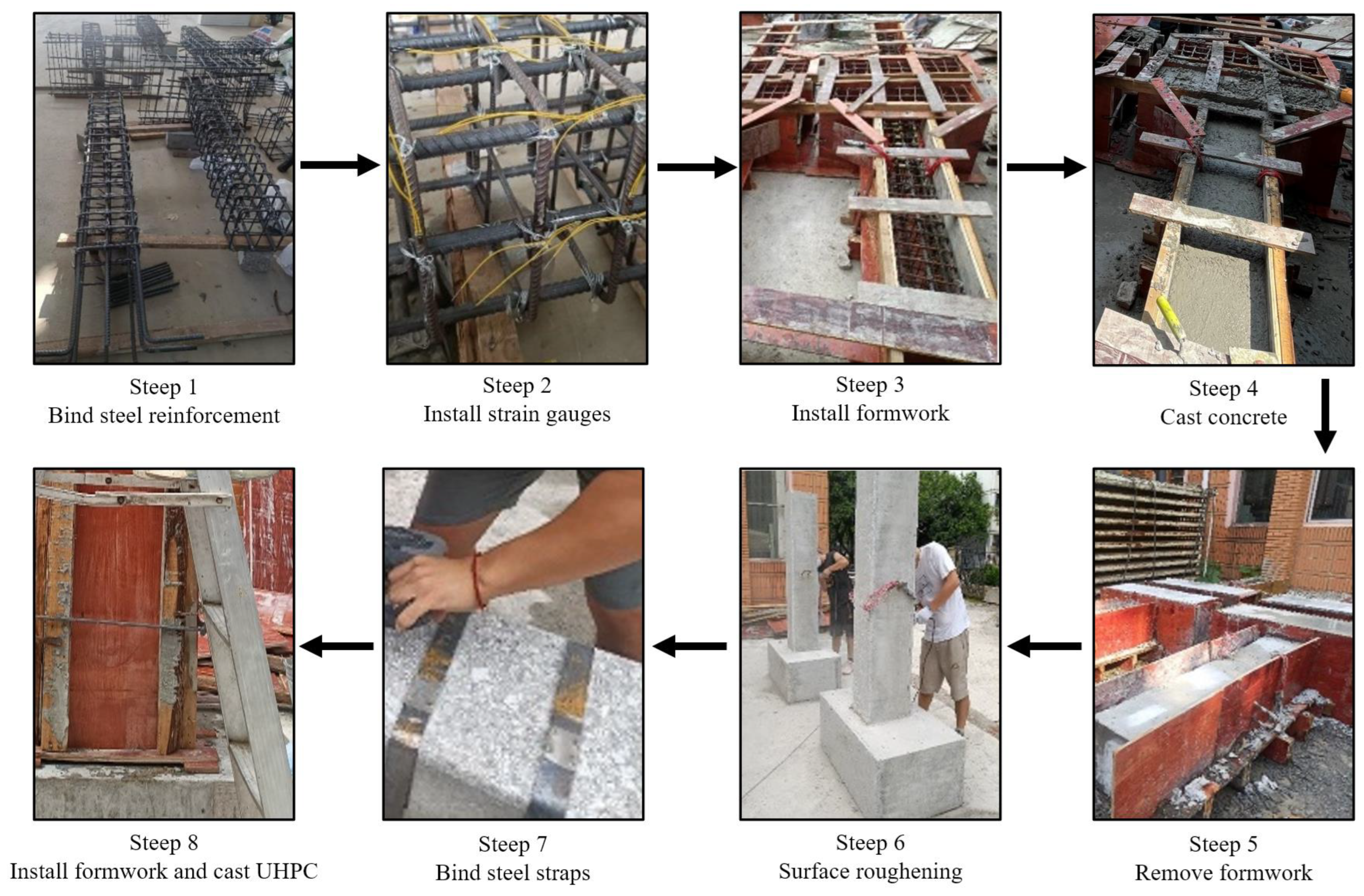
2.1. Specimen Design and Retrofit Scheme

In accordance with relevant codes [27,28], five full–scale specimens were designed, including one control column and four strengthened columns. The parameters of the specimens are listed in Table 1. Figure 1 illustrates the configuration and strengthening details of the test specimens. All specimens were designed based on Chinese design standards. Each column had a cross–section of 300 mm × 300 mm and was reinforced with eight HRB600–grade longitudinal bars of 16 mm diameter (HRB refers to a type of hot–rolled ribbed bar defined by Chinese national standards. The designation “600” indicates that the bar has a nominal yield strength of 600 MPa, which significantly exceeds that of conventional reinforcing steel). The foundation beam at the column base was reinforced with eight 14 mm diameter HRB600–grade longitudinal bars. Both the columns and the foundation beams were transversely reinforced with 8 mm diameter HRB600–grade stirrups spaced at 100 mm intervals. The control specimen was labeled RC–1, as shown in Figure 1a.
The configuration of the UHPC–strengthened column is shown in Figure 1b. Except for the connection region, all details of the UHPC–strengthened specimens were identical to those of specimen RC–1 (RCU–2 and RCU–3 were reinforced with UHPC layers of 25 mm and 35 mm thickness, respectively). The UHPC layer was cast in place to fully encase the column. To enhance the bond between the UHPC and the original concrete, the surface of the column was roughened at the interface. Additionally, grooves measuring 40 mm in width and 40 mm in depth were chiseled at the junction between the column and the foundation beam to improve the anchorage of the strengthening material. To evaluate the influence of UHPC layer thickness and composite steel–strip reinforcement on seismic performance, specimens RCUS–4 and RCUS–5 were designed with thicker UHPC layers and composite reinforcement, as illustrated in Figure 1c. In these specimens, steel strips were first wrapped around the column perimeter, followed by casting UHPC layers with thicknesses of 25 mm and 35 mm, respectively. All other procedures were consistent with those used for the UHPC–strengthened specimens. The overall strengthening procedure is illustrated in Figure 2.
The column and the foundation beam were cast simultaneously. Specimen RC–1 was constructed using conventional monolithic concrete construction techniques. For the retrofitted specimens, the UHPC strengthening layer was cast after the RC columns had fully hardened. Upon completion of the strengthening process, the specimens were cured under natural conditions for 28 days.

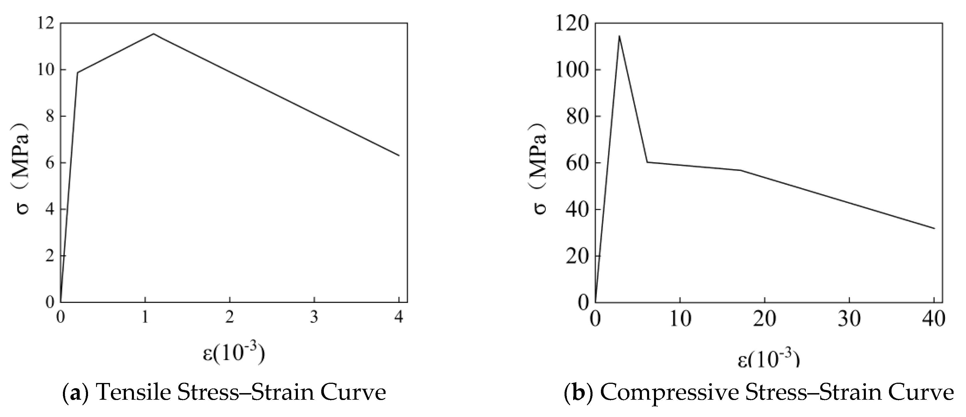
2.2. Properties of Material

The material properties of the ordinary concrete were tested in accordance with the relevant code [29]. The UHPC used for reinforcing the specimens is the pre–mixed material UC150 Mpa, which includes a mixture of silica fume, cement, fly ash, and other components. The powder and steel fibers were mixed in a 10:1 ratio, then blended using a forced mixer before being poured into the reinforcement specimens. According to the specifications outlined in GB/T31387–2015 [30] and T/CBMF37–2018 [31], all specimens and reinforced specimens were placed in the same environment for natural curing, during which continuous moisture maintenance was carried out., and its properties were tested following the procedures outlined in [32]. The results are presented in Table 2, with the stress–strain curve of the UHPC shown in Figure 3. The mechanical properties of the reinforcing steel bars and steel strips were evaluated using the tensile test method specified in [33], with the corresponding results shown in Table 3 and Table 4.

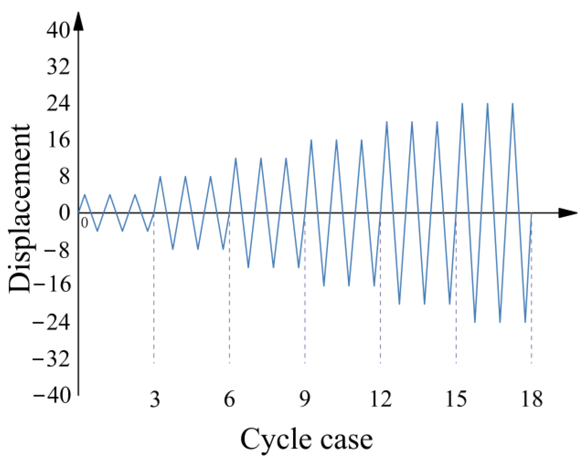
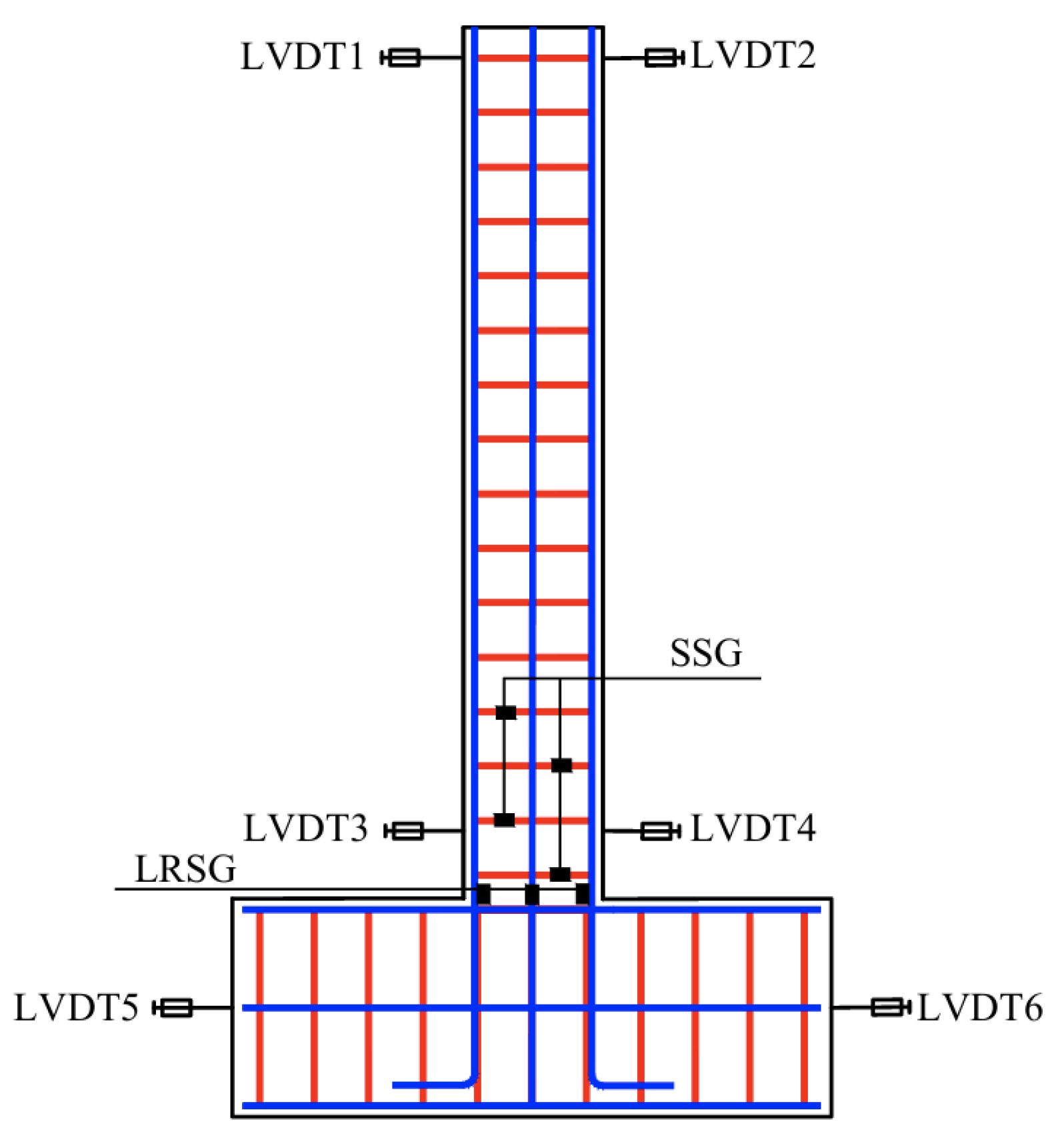
2.3. Test Device and Loading Procedure

A 2000 kN hydraulic jack was first used to apply a predetermined axial load to the top of the test specimens. During the test, this axial load was maintained constant. The axial load ratio was 0.4, with the applied axial load being 1000 kN for the unstrengthened specimen, 1606 kN for the specimen strengthened with a 25 mm–thick UHPC layer, and 1965 kN for the specimen strengthened with a 35 mm– thick UHPC layer. A multi–channel servo control system (MTS 100 t) was used to apply the lateral load via actuators. The base beam was anchored to the floor through compression beams to prevent sliding. The experimental loading setup is illustrated in Figure 4. The test began by applying the vertical axial load, which was held constant once the target axial load ratio was reached. According to the testing protocol [33], a displacement–controlled cyclic loading method was adopted, with a displacement increment of 4 mm per cycle (5 mm for RC–1). Each displacement level was repeated three times. The loading process was terminated when the specimen failed or the load dropped below 85% of the peak value. The loading protocol is shown in Figure 5, and the arrangement of strain gauges and displacement meters is shown in Figure 6.

3. Analysis and Discussion of Test Results

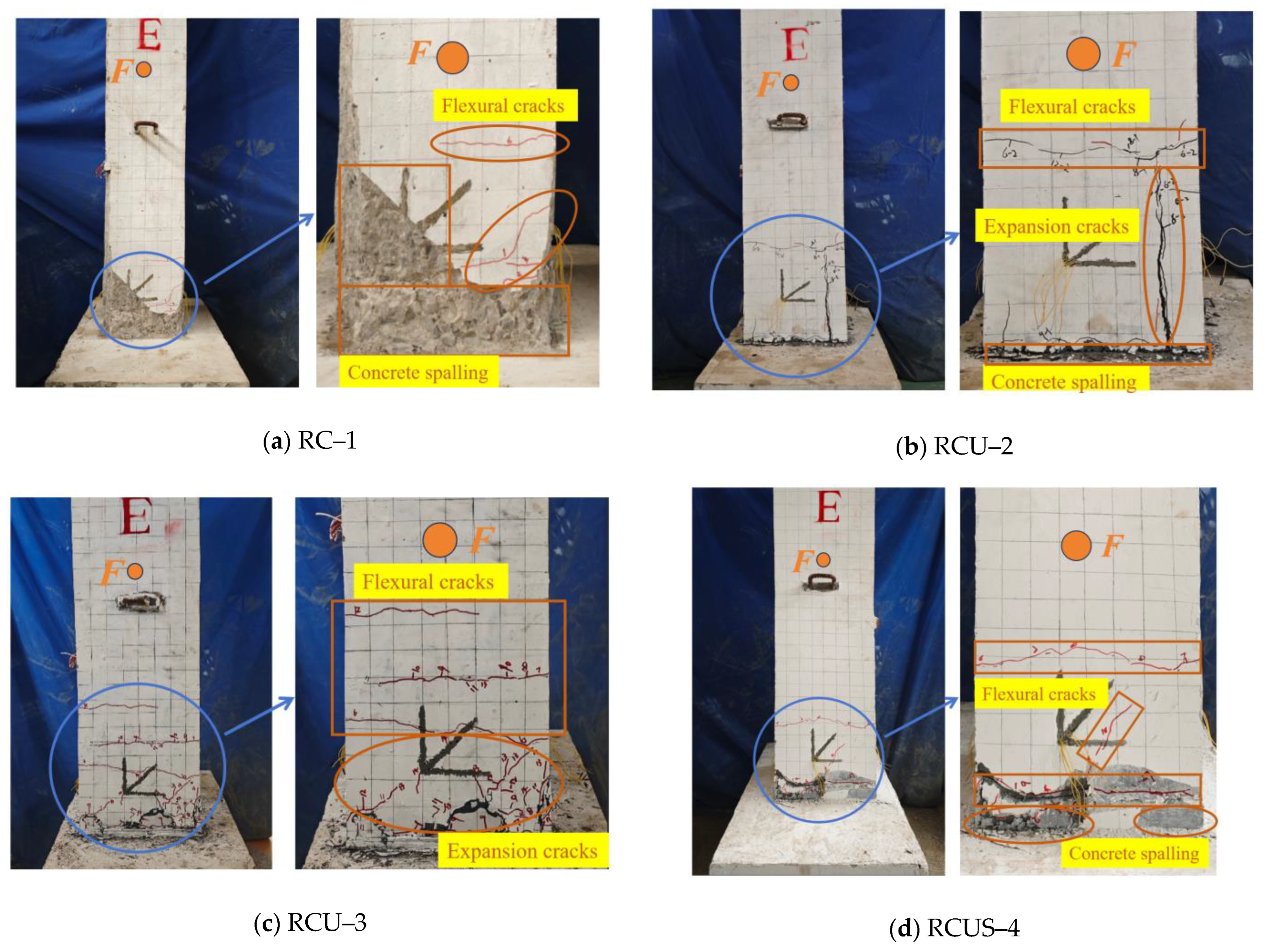
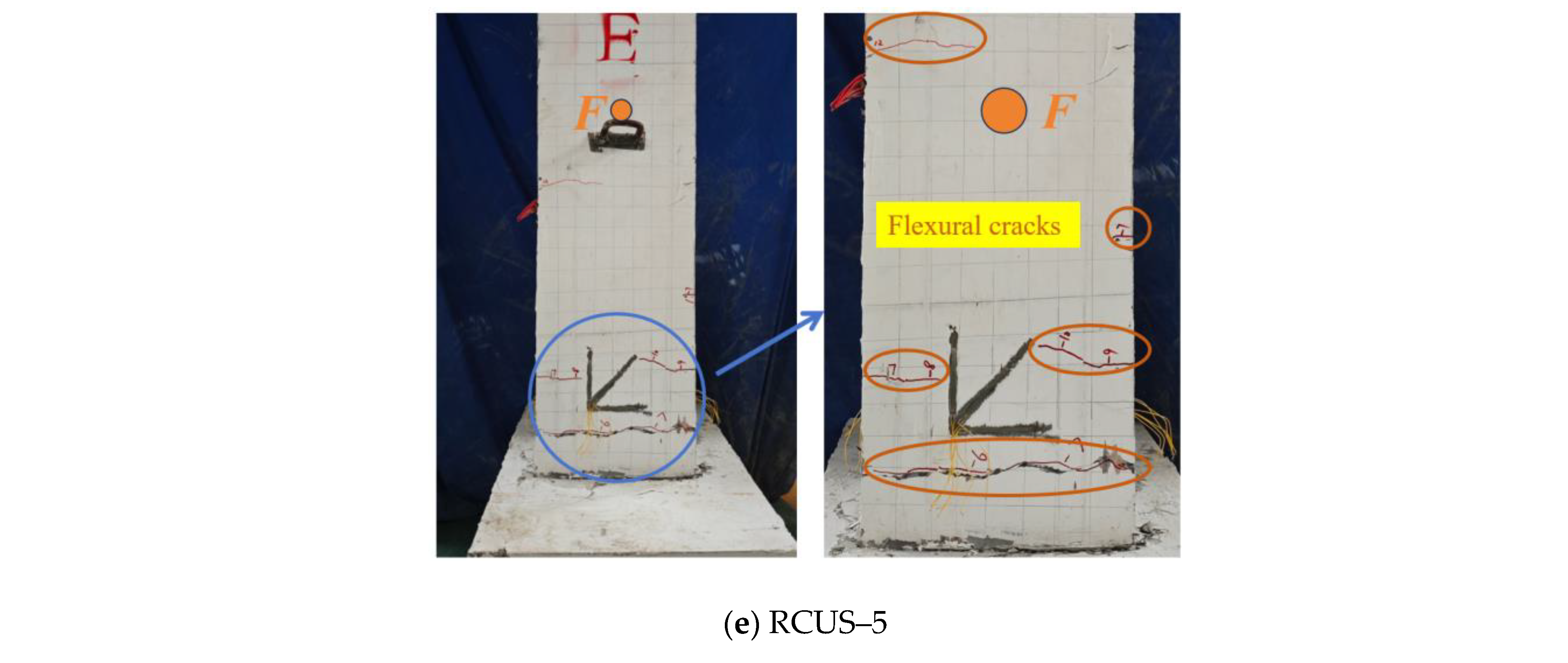
3.1. Damage Evolution of Columns

The experimental results reveal significant differences in the failure modes of the specimens under various strengthening methods. The observed failure patterns are shown in Figure 7. The unstrengthened control column RC–1 exhibited a typical flexural failure mode with distinct progressive stages:
(1)
At a displacement of 15 mm, the first flexural crack appeared on the column body (width < 0.1 mm). As the displacement increased to 20 mm, a 45° inclined crack formed at the column base accompanied by concrete spalling. At 25 mm, extensive crushing of concrete occurred at the base. Final failure occurred at a displacement of 30 mm due to buckling of the longitudinal reinforcement, at which point the load had dropped below 85% of the peak value. This failure mode resulted from the high axial load ratio (0.4), which suppressed flexural crack development but intensified brittle crushing in the compression zone. The plastic hinge localized at the column base led to a sudden decline in load–bearing capacity.
(2)
In contrast, the UHPC–strengthened columns (RCU–2 and RCU–3) exhibited a mixed flexural–shear failure mode. RCU–2 developed vertical cracks at a displacement of 25 mm; at 50 mm, inclined cracks extended toward the mid–height of the column (width < 0.3 mm), and at 65 mm, debonding occurred at the interface between the UHPC layer and core concrete. In RCU–3, which had a thicker UHPC layer, inclined cracks were more uniformly distributed (spacing ~60 mm), and a dense network of microcracks (width < 0.2 mm) formed at the column base. These observations confirm that UHPC’s high tensile strength and the bridging effect of steel fibers effectively restrained crack propagation.
(3)
The UHPC–steel strip composite strengthened columns (RCUS–4 and RCUS–5) predominantly exhibited ductile flexural failure. RCUS–4 showed horizontal cracking at a displacement of 30 mm, with the steel strip reaching 60% of its yield strain. At 60 mm, the specimen reached a peak load of 333.19 kN, and the cracks presented as multiple fine cracks (maximum width 0.15 mm). For RCUS–5, the effect of the steel strips resulted in a 50% reduction in the number of cracks, with no through–cracks observed.
In the unstrengthened specimen RC–1, a localized damage zone formed in the middle region, indicating that during flexural failure, the application of a UHPC layer or the UHPC–steel strip composite strengthening technique provides a broader control surface, thereby enhancing shear resistance. As shown in Figure 7, the crack distribution in the four strengthened specimens is notably denser than that in the unstrengthened RC–1. The strengthening of the concrete in the inclined section core is more effective, leading to greater energy dissipation. While the failure mode of the unstrengthened specimen RC–1 is characterized by flexural failure, the failure modes of the four strengthened specimens are primarily flexural–shear. The strengthened specimens exhibited a more stable bending response, demonstrating improved ductility and energy dissipation capacity.
The synergistic mechanism of composite strengthening manifests in three key aspects: (1) The steel strip increases the equivalent stirrup ratio by 30%, thereby constraining the expansion of concrete; (2) The UHPC layer delays stiffness degradation, allowing the plastic hinge region to extend up to 1.5 times the column diameter; (3) The optimization of interfacial bond strength redistributes the load, ultimately reducing the area of concrete crushing.

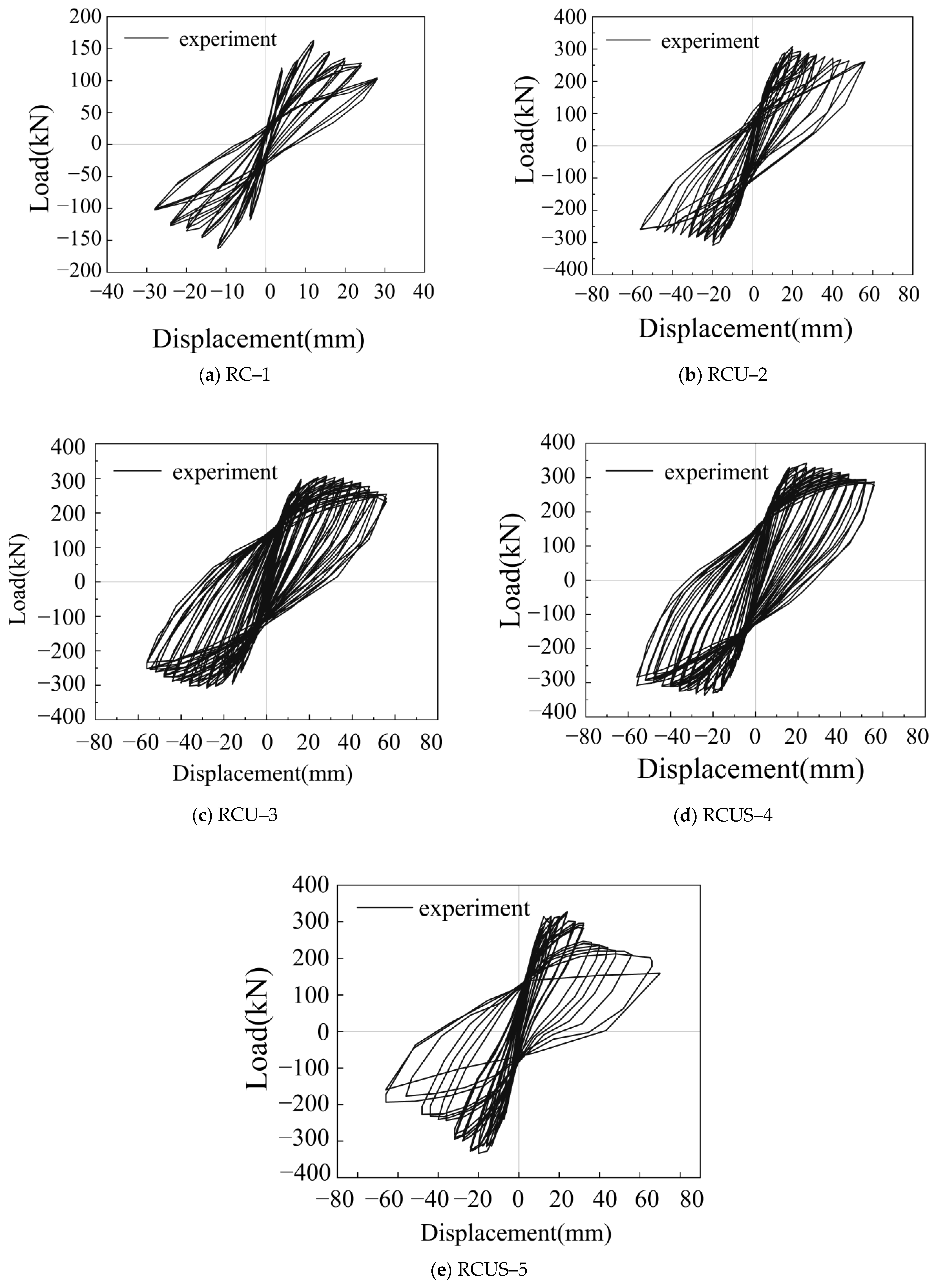
3.2. Hysteresis Curves

The hysteresis curves of the specimens are shown in Figure 8. The load–displacement hysteresis curves for all specimens exhibit similar shapes. In the elastic phase, the hysteresis curves are narrow and elongated, with small loop areas, and minimal residual displacement upon unloading. The inclination of the curves during the loading process remains consistent. As the horizontal displacement increases, the columns gradually reach the yielding phase. After yielding, the hysteresis curves begin to deviate from the linear path, and as the residual deformation increases post–unloading, the loop area expands, indicating an increase in the cumulative energy dissipation of the specimens. After reaching the peak load, the concrete progressively ceases to contribute, resulting in varying degrees of decline in horizontal load.
(1)
When the UHPC reinforcement layer thickness increases by 10 mm, the hysteresis loops of the UHPC–strengthened and UHPC–steel strip composite–reinforced specimens become fuller, with less decay in resistance at each load level and no significant pinching effect. This is primarily due to the increased thickness of the UHPC reinforcement layer, which enlarges the leverage of the reinforcing bars, thereby increasing their contribution to internal force distribution.
(2)
In UHPC–steel strip composite–reinforced specimens, compared to those with the same UHPC reinforcement thickness, the number of hysteresis loops increases slightly, and the loop areas become more pronounced. This suggests that the steel strip composite reinforcement enhances the confinement of the core concrete, limiting its lateral expansion. However, after the steel strip composite reinforcement, increasing the thickness of the UHPC layer does not result in a significant increase in peak load. While the number of hysteresis loops remains unchanged, their shape becomes fuller, and the energy dissipation capability improves. This indicates that the steel strip has already provided sufficient confinement, and further increasing the UHPC reinforcement thickness only enhances the plastic deformation capacity of the component without significantly improving the peak load.

3.3. Skeleton Curves and Ductility Index

The skeleton curves of the specimens are shown in Figure 9. The trends of the skeleton curves for all specimens are generally consistent; however, the reinforced specimens exhibit a significant increase in both the ductility coefficient and the ultimate displacement angle. This indicates that UHPC reinforcement and UHPC–steel strip composite reinforcement enhance the rotational capacity of the plastic hinge in the specimens.
The characteristic test results of the specimens are shown in Table 5. When UHPC is used for reinforcement, increasing the thickness of the UHPC layer leads to a 17.23% improvement in the ductility coefficient and a 6.06% increase in peak load. This demonstrates that increasing the UHPC reinforcement layer thickness can effectively enhance both the ductility and peak load of the specimens. For UHPC–steel strip composite reinforcement, compared to the same thickness of the UHPC reinforcement layer, the ductility coefficient of the specimens increased by 29.48% and 21.47%, and the peak load increased by 10.36% and 6.36%, respectively. This indicates that the synergistic effect of UHPC and steel strips can further improve the specimens’ plastic deformation capacity. A comparison of the RCU–2, RCPU–3, and RCUS–4 specimens shows that the UHPC–steel strip composite reinforcement is more effective than increasing the UHPC reinforcement layer thickness in improving ductility. This suggests that the embedded steel strips constrain the core concrete more effectively than the increased UHPC thickness, inhibiting crack initiation and development more efficiently. Adding additional UHPC layers after composite steel strip reinforcement does not significantly affect the peak load but results in a marked improvement in ductility. This suggests that the bond–slip phenomenon between the steel strip and concrete occurs, which means that the steel strip no longer effectively constrains the core concrete.

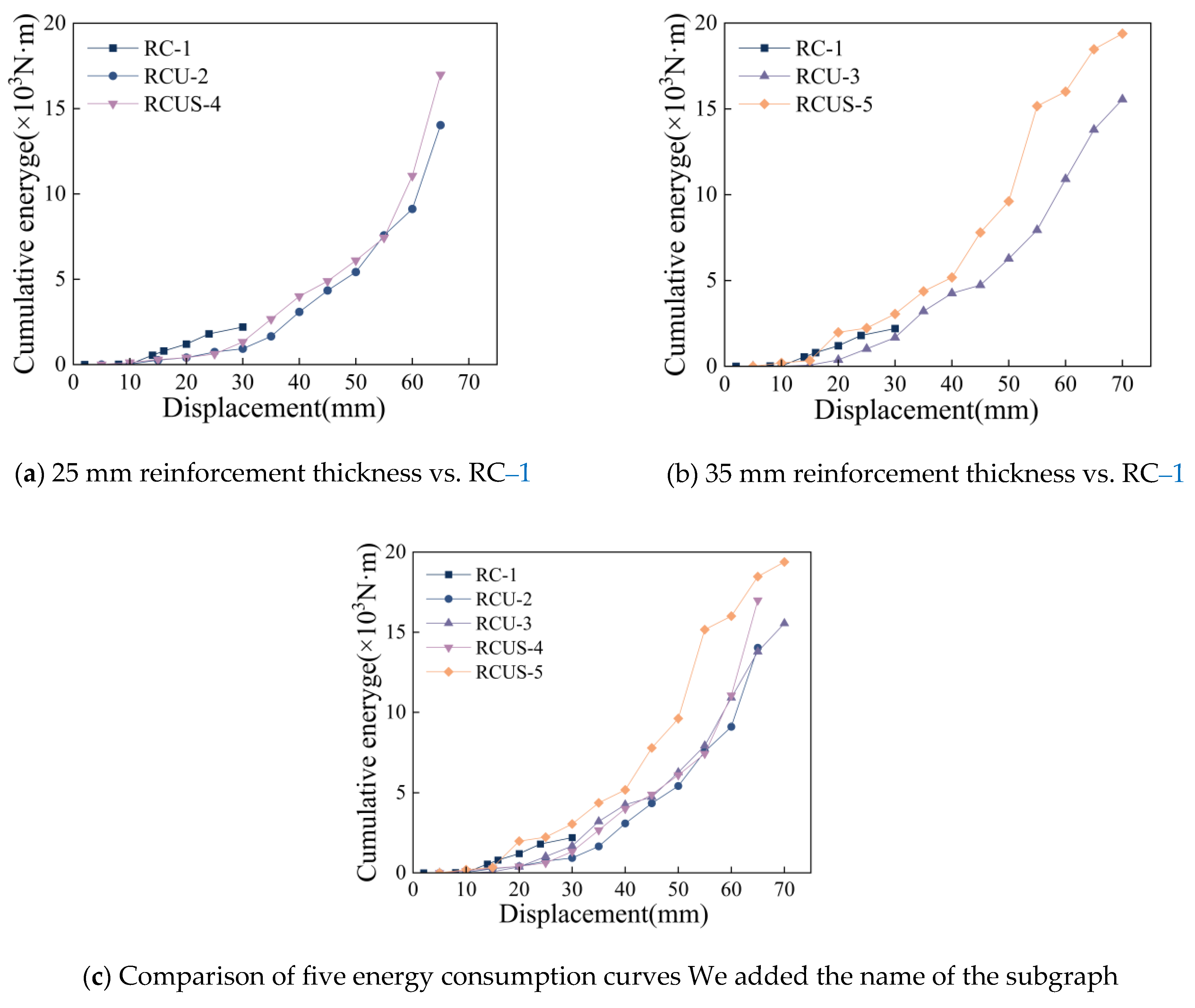
3.4. Energy Dissipation

The cumulative energy dissipation curves of the specimens are shown in Figure 10. During the early stages of loading, the cumulative energy dissipation of the specimens increases slowly. However, as the loading progresses, the increase in cumulative energy dissipation becomes more pronounced, indicating that the greater the plastic deformation of the specimen, the more energy is dissipated. As the thickness of the UHPC reinforcement layer increases, the energy dissipation capacity of the specimen is significantly enhanced. Thicker UHPC layers are more effective in resisting crack propagation, improving crack resistance and compressive strength, and prolonging the plastic deformation phase, thereby substantially increasing the specimen’s energy dissipation capacity.
Compared to the unreinforced RC–1 specimen, the cumulative energy dissipation of the RCPU–2 and RCPU–3 specimens increased by 67.71% and 85.87%, respectively. The cumulative energy dissipation of the RCUS–4 and RCUS–5 specimens increased by 115.00% and 119.71%, respectively. The cumulative energy dissipation of the RCPU–3 specimen increased by 18.21% compared to the RCPU–2 specimen, while the RCUS–4 specimen showed a 21.07% increase compared to the RCPU–2 specimen. Additionally, the RCUS–5 specimen exhibited a 14.09% increase in cumulative energy dissipation compared to the RCUS–4 specimen.
For specimens with the same UHPC reinforcement layer thickness, the UHPC–steel strip composite reinforcement demonstrates superior energy dissipation capability. This is primarily due to the greater lateral confinement provided by the steel strips, which more effectively suppress crack initiation and propagation, thereby improving the specimen’s ductility and enhancing its energy dissipation capacity.

3.5. Stiffness

In this paper, the cutline stiffness K i is used to measure the stiffness degradation pattern of the specimen, which is calculated according to Equation (1).
K i = + F i + F i + X i + X i
where: + F i , F i for the ith loading positive and negative peak point load value; + X i , X i for the ith loading positive and negative direction maximum displacement value.
The stiffness degradation of the specimens is shown in Figure 11. Compared to the unreinforced specimen RC–1, the specimens reinforced with UHPC and UHPC combined with steel strips exhibit an improvement in initial stiffness. Specifically, the UHPC–strengthened specimens demonstrate a faster rate of stiffness degradation before reaching the peak load; however, after the peak load, the stiffness degradation curves for all reinforced specimens flatten out. This confirms that both reinforcement methods effectively suppress stiffness degradation in RC columns with a high axial load ratio under strong seismic conditions.
Comparison of specimens with different parameters reveals that when the thickness of the UHPC reinforcement is appropriately increased (e.g., RCU–3 compared to RCPU–2), the initial stiffness improves, and the degradation slope decreases, indicating superior stiffness retention. In contrast, the specimens reinforced with UHPC combined with steel strips (RCUS–4 and RCUS–5) exhibit a slower stiffness degradation process compared to the pure UHPC–strengthened specimens (RCU–2 and RCPU–3). This reduction in degradation slope suggests that the steel strips’ constraint further delays stiffness deterioration. This composite reinforcement method is more capable of meeting the structural performance requirements under large deformations and high loads.

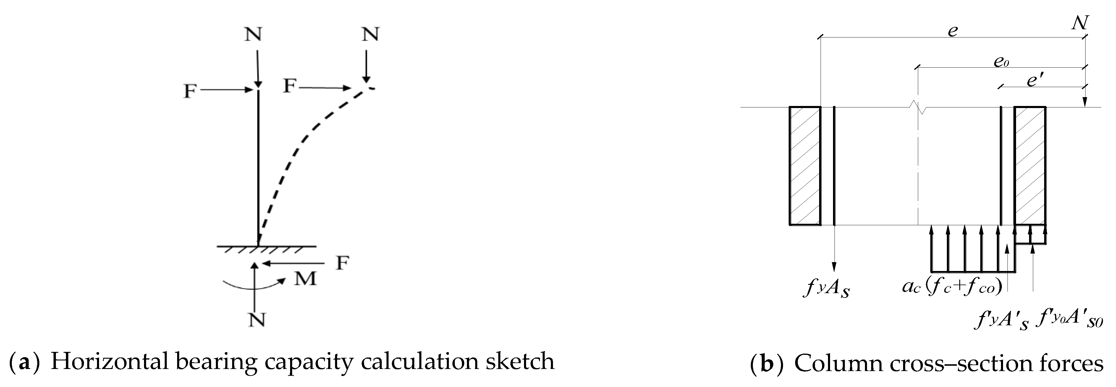
4. Bearing Capacity Calculation

4.1. Basic Assumptions of the Theoretical Model

To simplify the calculations, the following assumptions are made in accordance with the standards: (1) The cross–section of the reinforced column satisfies the plane section assumption; (2) Since the concrete in the cracked region of the specimen largely ceases to participate in load–bearing, and the tensile strength of the core concrete is relatively low, the tensile strength of the core concrete is neglected in the calculations; (3) During the experimental loading process, the UHPC layer remains well bonded with the core concrete, with no slippage or other issues observed; therefore, it is assumed that no slippage occurs at the interface in the calculations. The material mechanical properties, including the yield strength of the steel bars, yield strength of the steel strips, and the compressive strengths of ordinary concrete and UHPC, are based on the measured values presented in this study.

4.2. Limit Relative Depth of Compression Zone

In this paper, the height of the relative compression zone of the bending member is calculated according to Equations (2)–(4) with reference to the code [27]:
ξ b = β 1 1 + α 1 f y ε c u E s + ε s 1 ε c u
ε s 1 = ( 1.6 h 0 h 01 0.6 ) ε s 0
ε s 0 = M 0 k 0.85 h 01 A s 0 E s 0
where: β 1 is for the calculation coefficient; when the concrete strength grade does not exceed C50, the β 1 value is taken as 0.80; when the concrete strength grade is C80, the β 1 value is taken as 0.74, which is determined by linear interpolation; α 1 is the ratio of the stress value of the rectangular stress diagram of concrete in the compression zone to the design value of the axial compressive strength of concrete; when the concrete strength grade does not exceed C50, take α 1 = 1.0; when the concrete strength grade is C80, take α 1 = 0.94; the intermediate is determined by the linear interpolation method, f y is the design values of the tensile strength of the reinforcement (mm2), ξ b is the height of the compression zone relative to the limits of the member after increasing the cross–section reinforcement (mm), h 0 is the effective height of the original section (mm), h 01 is the effective height of the section of the member (mm), E s is the modulus of elasticity of reinforcement, E s 0 is the modulus of elasticity of the original concrete, ε c u is for the ultimate compressive strain of the new and old concrete according to the average value of the cross–section area, ε s 1 is for the location of the new steel strip here, according to the assumption of the flat cross–section determined by the initial strain value (με), and M 0 k is, for the test column, the design value of the original bending moment of the section of the bent member before reinforcement (kN/mm), and ε s 0 is the strain value of the original tensile reinforcement under the action of the initial bending moment before reinforcement (με).

4.3. Balanced Flexural Capacity Calculation

Based on the calculation method of the horizontal ultimate load capacity of RC columns, the horizontal ultimate load capacity of UHPC–composite steel strip reinforced RC columns were deduced and calculated, and the test results were compared and analyzed with the calculation results. The cross section of the calculated bending capacity of UHPC–composite steel strip reinforced RC columns is shown in Figure 12a,b.
From the moment of equilibrium condition Equation (5) and the force equilibrium condition Equation (6):
M = F l + N e
F = M N e l
Obtain Equation (7), Equation (8):
N α 1 ( f c 0 A 0 + α c f c A c + α t f t A c ) + f y A s f y A s
M α 1 ( f c 0 b h 01 + α c f c A c + α t f t A c ) + f y A s ( x 2 a )
where the height x of the concrete compression zone ranges as in Equation (9):
2 a x ξ b h 01
where: M is the design value of the bending moment after reinforcement (kN/mm); f c , f c 0 are the measured axial compressive strengths of the original concrete and UHPC, respectively. f t was the measured tensile strength of the UHPC; α c is the coefficient of utilization of the axial compressive strength of the newly reinforced concrete taken here; A c is the cross–sectional area of the newly reinforced concrete (mm2); f y is the design values of the compressive strength of the reinforcement (mm2), respectively; A s , A s are the cross–sectional areas of the tensile and compressive reinforcement (mm2), respectively; x is the height of the concrete compression zone (mm); b is the width of the rectangular section (mm).
The length–to–finish ratio of the member is determined by the second–order effects formula, and if Equation (10) is satisfied, the effect of axial pressure on the curvature and bending moment increments under flexural deformation can be neglected.
l c i 34 12 M 1 M 2
where: M 1 , M 2 for the eccentric compression member has been considered the effect of lateral displacement of the same main axis of the combined design value of the moment, where M 2 for the member of the absolute value of the moment at both ends corresponds to the larger end; l c for the calculation of the length of the member; i for the radius of gyration of the member section. i = I A = h 1 12 calculated by l c i = 2 l h 12 = 2 × 1600 400 12 = 27.71 < 34 cannot consider the influence of second–order effects.
In summary, the horizontal ultimate bending capacity at the base of the column is given by Equation (11).
F = α 1 ( f c 0 b h 0 + α c f c A c + α t f t A c ) + f y A s ( x 2 a s ) N ( e 0 + e a + h 2 a s ) l
where: N is the axial pressure (kN); F is the horizontal ultimate bending capacity (kN), according to the bending bearing capacity formula calculation of the calculated value and the test value of the comparison shown in Table 6.
As shown in Table 6, the experimental values of the specimens are in good agreement with the theoretically calculated values, with a relative error within 15%. The discrepancy between the calculated horizontal ultimate bending capacity and the experimental load–bearing capacity may be attributed to slippage between the material bonds. Additionally, the utilization factor for the cooperative action of the materials used in the experiments requires further determination.

5. Discussion and Conclusions

5.1. Discussion

(1)
ACI 318–19 emphasizes the importance of structural ductility design, requiring components to possess sufficient deformation capacity within the plastic hinge region. In this study, the UHPC–composite steel strip reinforcement significantly improved the displacement ductility coefficient (e.g., RCUS–5 with μ = 6.28), meeting the ductility requirements of ACI 318. However, the code does not explicitly permit the use of UHPC and steel strip composite reinforcement, necessitating adjustments in equivalent stirrup ratios or material properties to comply with existing provisions. Eurocode 8 requires structures to exhibit a “strong column–weak beam” mechanism and sufficient energy dissipation capacity. In this study, the hysteresis loops of the UHPC–composite reinforced columns are more pronounced, and energy dissipation capacity has been enhanced, which aligns with the energy dissipation requirements of Eurocode 8.
(2)
The steel strip–UHPC composite reinforcement technique proposed in this study demonstrates significant advantages in practical engineering applications. In terms of construction efficiency, the installation of steel strips is approximately 40% faster than traditional steel jackets. When combined with prefabricated UHPC components, the construction period can be significantly shortened. From an economic perspective, material costs are reduced by approximately 30% and 22% compared to FRP and steel jackets, respectively, while life–cycle maintenance costs are lowered by over 50%. This technique is particularly suitable for the rapid seismic retrofitting of columns with high axial load ratios (0.3–0.5). By employing a standardized construction process—including pre–tension control between 20–30 kN and an interface roughness of Ra ≥ 50 μm—the method achieves substantial seismic upgrading with minimal interference to the appearance of historic buildings, as the reinforcement layer is only 25–35 mm thick. Overall, the approach reduces seismic retrofit costs by approximately 35–40% and offers considerable potential for widespread engineering application.
(3)
The UHPC–composite steel band reinforcement achieves a simultaneous enhancement of stiffness, initial strength, and ductility through the synergistic interaction of materials and construction. Under service–level events, the reinforced structure not only maintains a high elastic stiffness but also effectively addresses accidental overloading through ductility design, in accordance with modern seismic codes (such as ACI 318 and Eurocode 8), which require a “strong column–weak beam” mechanism and energy dissipation. Future research could further quantify the changes in stiffness at the service level, optimizing the reinforcement layer thickness and steel band layout to balance economic and performance demands.

5.2. Conclusions

(1)
The failure modes of the reinforced specimens have significantly improved. Compared to the unreinforced specimens, the reinforced specimens exhibit bending–shear failure, with fine diagonal cracks appearing at the bottom of the UHPC–strengthened specimens. In comparison to the UHPC–strengthened specimens, the UHPC–composite steel strip reinforced specimens show only a few diagonal cracks, indicating that both UHPC reinforcement and UHPC–composite steel strip reinforcement can improve the failure modes of the specimens. However, the UHPC–composite steel strip reinforcement is more effective in restraining the initiation and propagation of cracks.
(2)
The increased thickness of the UHPC reinforcement layer effectively enhances the seismic performance of the structure. With an increase of 10 mm in the UHPC reinforcement layer thickness, the peak load of the UHPC–strengthened specimens increased by 6.06%, the displacement ductility improved by 17.23%, and the energy dissipation capacity increased by 18.21%. For the UHPC–composite steel strip reinforced specimens, the peak load increased by 2.22%, the displacement ductility improved by 9.98%, and the energy dissipation capacity increased by 14.09%. Furthermore, the hysteresis loops became more complete, and the stiffness degradation was significantly improved.
(3)
Compared to specimens strengthened solely with UHPC, the composite specimens reinforced with steel bands exhibited increases in peak load of 10.36% and 6.36% for reinforcement layer thicknesses of 25 mm and 35 mm, respectively. The ductility coefficients increased by 29.47% and 21.47%, accompanied by significant enhancements in energy dissipation capacity. The hysteresis loops became larger and more stable, indicating further improvements in energy absorption and stiffness degradation. Moreover, under the same seismic performance requirements, the inclusion of steel bands effectively reduced the required thickness of the UHPC layer, demonstrating a strong synergistic effect among the three components.
(4)
Based on moment equilibrium, the proposed calculation formula for the horizontal ultimate bending capacity yields a calculation value with an error within 15% of the experimental values, demonstrating good agreement. This formula provides theoretical guidance for engineering applications.

Author Contributions

Conceptualization, X.L.; experiment, M.P. and W.C.; resources, X.L.; writing—original draft preparation, M.P.; writing—review & editing, W.C.; supervision, Z.W.; project administration, X.L. All authors have read and agreed to the published version of the manuscript.

Funding

This study was funded by the Key Research and Development Project of Guangxi, China (No. AB23075093).

Data Availability Statement

Data will be made available on request. All data, models, or codes that support the findings of this study are available from the corresponding author on reasonable request.

Conflicts of Interest

The authors declare no conflict of interest.

References

  1. GB 50010—2010; Code for Design of Concrete Structures. China Architecture & Building Press: Beijing, China, 2011. (In Chinese)
  2. ACI 318–19; Building Code Requirements for Structural Concrete and Commentary. American Concrete Institute: Farmington Hills, MI, USA, 2019; pp. 435–454. [CrossRef]
  3. Lubkowski, Z.A.; Duan, X. EN1998 Eurocode 8: Design of Structures for Earthquake Resistance; Springer: Berlin/Heidelberg, Germany, 2014. [Google Scholar]
  4. Li, H.; Xiao, S.; Huo, L. Damage investigation and analysis of engineering structures in the Wenchuan earthquake. J. Build. Struct. 2008, 9, 10–19. [Google Scholar]
  5. Miller, D.K. Lessons learned from the Northridge earthquake—ScienceDirect. Eng. Struct. 1998, 20, 249–260. [Google Scholar] [CrossRef]
  6. Sezen, H.; Whittaker, A.S.; Elwood, K.J.; Mosalam, K.M. Performance of reinforced concrete buildings during the August 17, 1999 Kocaeli, Turkey earthquake, and seismic design and construction practise in Turkey. Eng. Struct. 2003, 25, 103–114. [Google Scholar] [CrossRef]
  7. Fu, T.; Wang, K.; Zhu, Z.; Ren, X.; Li, Y.; Xu, L.; Meng, L.; Sun, Z. Seismic performance of prefabricated square hollow section piers strengthened by jacketing using UHPC and high–strength steel. Structures 2023, 47, 449–465. [Google Scholar] [CrossRef]
  8. Nuroji, N.; Hung, C.C.; Prasetya, B.H.; Han, A. The Behavior of Reinforced Concrete Members with Section Enlargement Using Self–Compacting Concrete. Int. Rev. Civ. Eng. (IRECE) 2020, 11, 121. [Google Scholar] [CrossRef]
  9. Belal, M.F.; Mohamed, H.M.; Morad, S.A. Behavior of reinforced concrete columns strengthened by steel jacket. HBRC J. 2015, 11, 201–212. [Google Scholar] [CrossRef]
  10. Pudjisuryadi, P.; Tavio Suprobo, P. Performance of Square Reinforced Concrete Columns Externally Confined by Steel Angle Collars Under Combined Axial and Lateral Load. Procedia Eng. 2015, 125, 1043–1049. [Google Scholar] [CrossRef]
  11. Iacobucci, R.D.; Sheikh, S.A.; Bayrak, O. Retrofit of Square Concrete Columns with Carbon Fiber–Reinforced Polymer for Seismic Resistance. ACI Struct. J. 2003, 100, 785–794. [Google Scholar]
  12. Kang, L.; Bang, L.; Soo, S. A Seismic Strengthening Technique for Reinforced Concrete Columns Using Sprayed FRP. Polymers 2016, 8, 107. [Google Scholar] [CrossRef]
  13. Xia, Z.; Lin, L.; Zhang, J.; Jiang, S. Seismic performance of underwater RC bridge piers strengthened with self–compacting concrete–filled BFRP jacket. Structures 2022, 39, 637–652. [Google Scholar] [CrossRef]
  14. Zhang, Y.; Zhu, P.; Liao, Z.; Wang, L. Interfacial bond properties between normal strength concrete substrate and ultra–high performance concrete as a repair material. Constr. Build. Mater. 2020, 235, 117431. [Google Scholar] [CrossRef]
  15. John, S.K.; Cascardi, A.; Verre, S.; Nadir, Y. Rc–columns subjected to lateral cyclic force with different frcm–strengthening schemes: Experimental and numerical investigation. Bull. Earthq. Eng. 2025, 23, 1561–1590. [Google Scholar] [CrossRef]
  16. Alhoubi, Y.; El Refai, A.; Abed, F.; El–Maaddawy, T.; Tello, N. Strengthening pre–damaged rc square columns with fabric–reinforced cementitious matrix (frcm): Experimental investigation. Compos. Struct. 2022, 294, 115784. [Google Scholar] [CrossRef]
  17. Farzad, M.; Shafieifar, M.; Azizinamini, A. Experimental and numerical study on bond strength between conventional concrete and Ultra High–Performance Concrete (UHPC). Eng. Struct. 2019, 186, 297–305. [Google Scholar] [CrossRef]
  18. Feng, S.; Xiao, H.; Li, H. Comparative studies of the effect of ultrahigh–performance concrete and normal concrete as repair materials on interfacial bond properties and microstructure. Eng. Struct. 2020, 222, 111122. [Google Scholar] [CrossRef]
  19. Aboukifa, M.; Moustafa, M.A. Experimental seismic behavior of ultra–high performance concrete columns with high strength steel reinforcement. Eng. Struct. 2021, 232, 111885. [Google Scholar] [CrossRef]
  20. Guan, D.; Chen, Z.; Liu, J.; Lin, Z.; Guo, Z. Seismic performance of precast concrete columns with prefabricated UHPC jackets in plastic hinge zone. Eng. Struct. 2021, 245, 112776. [Google Scholar] [CrossRef]
  21. Shao, Y.; Kuo, C.W.; Hung, C.C. Seismic performance of full–scale UHPC–jacket–strengthened RC columns under high axial loads. Eng. Struct. 2021, 243, 112657. [Google Scholar] [CrossRef]
  22. Tong, T.; Lei, H.; Yuan, S.; Liu, Z. Experimental investigation and seismic vulnerability assessment of low flexural strength rectangular bridge piers retrofitted with ultrahigh–performance concrete jackets. Eng. Struct. 2020, 206, 110132. [Google Scholar] [CrossRef]
  23. Hung, C.C.; Lin, C.C.; Do, T.D.D. Seismic rehabilitation of RC frames with innovative precast U–shaped UHPC jackets: Experimental evaluation and computational simulation. Eng. Struct. 2024, 318, 16. [Google Scholar] [CrossRef]
  24. Zhu, M. Seismic Performance of Reinforced Concrete Column Retrofitted with UHPC Jacketing Enhanced by Stainless Steel Matrix. Master’s Thesis, Southeast University, Nanjing, China, 2023. [Google Scholar]
  25. Ding, Y.; Zeng, B.; Zhou, Z.; Wei, Y.; Zhu, M. Seismic retrofitting of RC columns using stainless steel grid–reinforced UHPC jackets in plastic hinge zone. J. Build. Eng. 2024, 84, 108637. [Google Scholar] [CrossRef]
  26. Zhang, Y.; Li, R.; Deng, M.; Dai, L. Experimental study on seismic behavior of RC columns strengthened with ultra–high performance concrete jacket. J. Build. Struct. 2023, 44, 88–98. [Google Scholar] [CrossRef]
  27. GB 50011—2010; Code for Seismic Design of Buildings. China Architecture & Building Press: Beijing, China, 2016. (In Chinese)
  28. GB 50367—2013; Code for Design of Strengthening Concrete Structure. China Architecture & Building Press: Beijing, China, 2013. (In Chinese)
  29. GB/T 50081—2019; Standard for Test Methods of Concrete Physical and Mechanical Properties. Standards Press of China: Beijing, China, 2019. (In Chinese)
  30. GB/T 31387–2015; Reactive Powder Concrete. China Standard Press: Beijing, China, 2015. (In Chinese)
  31. T/CBMF 37–2018, T/CCPA 7–2018; Fundamental Characteristic and Test Methods of Ultra–High Performance Concrete. China Architecture & Building Press: Beijing, China, 2019. (In Chinese)
  32. GB/T 228. 1—2021; Metallic Materials: Tensile Testing: Part 1: Method of Test at Room Temperature. Standards Press of China: Beijing, China, 2021. (In Chinese)
  33. JGJ 101—2015; Code for Seismic Testing of Buildings. China Architecture & Building Press: Beijing, China, 2015. (In Chinese)
Figure 1. Column reinforcement details.
Buildings 15 01762 g001
Figure 2. Reinforcement Flowchart.
Buildings 15 01762 g002
Figure 3. Stress–Strain Curve of UHPC.
Buildings 15 01762 g003
Figure 4. Test device of columns.
Buildings 15 01762 g004
Figure 5. Loading procedure of columns.
Buildings 15 01762 g005
Figure 6. Loading diagram and locations of strain gauges and LVDTs.
Buildings 15 01762 g006
Figure 7. Final failure form of columns.
Buildings 15 01762 g007aBuildings 15 01762 g007b
Figure 8. Hysteresis curves of columns.
Buildings 15 01762 g008
Figure 9. Skeleton curves of the specimens.
Buildings 15 01762 g009
Figure 10. Energy dissipation capacity of column.
Buildings 15 01762 g010
Figure 11. Stiffness.
Buildings 15 01762 g011
Figure 12. Sketch of section for calculation of bending capacity.
Buildings 15 01762 g012
Table 1. Design parameters of specimens.
SpecimensSteel Strip Width/mmThickness of Steel Strip/mmNumber of Layers of Steel StripSteel Strip Spacing/mmUHPC Reinforcement Thickness/mmAxial Pressure Ratio
RC–100.4
RCU–2250.4
RCU–3350.4
RCUS–4320.81150250.4
RCUS–5320.81150350.4
Table 2. Concrete properties.
Type of ConcreteCompressive Strength of the Cube/MPaAxial Compressive Strength of Cylinder/MPaElastic Modulus/GPaTensile Strength/MPa
C4042.5328.7131.942.32
UHPC134.82116.7445.0111.31
Table 3. The mechanical properties of reinforcing rebar.
Type of SteelDiameter/mmYield Strength/MPaUltimate Strength/MPaBreaking Strain/%
C8848360422
C141451964920
C161653667023
Table 4. Steel strip tensile properties.
Steel Strip NumberFailure Load/kNYield Strength/MPaUltimate Strength/MPaElastic Modulus/MPa
S118.186427321.79 × 105
S1–117.45613699
Note: S1 means no locking steel–strip specimen; S1–1 means two locking steel–strip specimens are bundled.
Table 5. Test results of specimen characteristic points.
SpecimenPy/kNΔy/mmPm/kNΔm/mmΔu/mmμ
RC–1130.486.93174.5314.9228.974.18
RCU–2243.7612.96285.8919.9257.114.41
RCU–3247.9612.57303.2124.0464.955.17
RCUS–4266.4311.02315.5123.9962.945.71
RCUS–5270.9411.04322.5224.0169.286.28
Note: Py, Δy are the yield load and yield displacement, respectively; Pm, Δm are the peak load and peak displacement, respectively; Δu is the ultimate displacement; μ is the displacement coefficient of ductility, μ = Δuy; θ is the ultimate displacement angle.
Table 6. Comparison of test and calculated values of horizontal ultimate bending capacity.
SpecimenExperimental Value/kNCalculated Value/kNExperimental Value/Calculated Value
RC–1174.53190.520.916
RCU–2285.89312.330.915
RCU–3303.21334.620.906
RCUS–4315.51353.110.894
RCUS–5322.52357.410.902
Disclaimer/Publisher’s Note: The statements, opinions and data contained in all publications are solely those of the individual author(s) and contributor(s) and not of MDPI and/or the editor(s). MDPI and/or the editor(s) disclaim responsibility for any injury to people or property resulting from any ideas, methods, instructions or products referred to in the content.

