Article

Mechanical Characteristics and Safety Evaluation of Tunnel Lining Structures in Karst Areas Under Heavy Rainfall Conditions

1
School of Mechanics and Civil Engineering, China University of Mining and Technology, Xuzhou 221116, China
2
State Key Laboratory of Intelligent Geotechnics and Tunnelling, Southwest Jiaotong University, Chengdu 610031, China
*
Author to whom correspondence should be addressed.
Buildings 2025, 15(10), 1756; https://doi.org/10.3390/buildings15101756
Submission received: 9 April 2025 / Revised: 8 May 2025 / Accepted: 16 May 2025 / Published: 21 May 2025
(This article belongs to the Section Building Structures)

Abstract

Karst tunnels accumulate localized high water pressure during heavy rainfall, which can potentially induce cracks and damage to tunnel structures. By fully analyzing the stress characteristics of the lining structure and the critical water pressure, this study aims to evaluate the safety status of karst tunnels under heavy rainfall conditions, and proposes detailed tunnel optimization solutions. The results indicate that the outward deformation of the structure is restricted when the water pressure within the cavity is low, thus enhancing structural stability. However, the internal forces of the structure gradually increase as water pressure increases. Additionally, the mechanical properties of the surrounding rock significantly influence the internal forces. The bending moment in the lining structure is highest in the grade III surrounding rock under the same water pressure. However, the critical water pressure of the lining structure differs by surrounding rock grade due to varying constraints, following the order IV > V > III. Moreover, karst cavities located at the arch spandrel exert the greatest detrimental effect on the structure. Furthermore, the critical water pressure and concrete failure modes of the lining structure under different conditions are determined. Lastly, the optimization of the construction and design of the actual tunnel is proposed to enhance the structural integrity of the tunnel lining. These findings provide valuable insights for structural safety assessments under various karst cavity conditions.

1. Introduction

The karst landscape in China covers over one-third of the country’s total area, forming extensive karst landscapes [1]. As a key solution for crossing mountainous regions, tunnels inevitably face water-related hazards, including water inrush, mud inrush, and secondary lining cracking, when passing through karst areas [2,3,4,5]. During seasonal heavy rainfall, surface water infiltrates karst cavities through complex karst pipelines, generating high water pressure on local tunnel structures and posing significant threats to structural safety. Heavy rainfall has caused lining cracks or even structural failure in karst tunnels, such as the Nanling Tunnel on the Beijing–Guangzhou Railway [6] and the Meihuashan Tunnel on the Guiyang–Kunming Railway [7]. The Maluqing Tunnel on the Yichang–Wanzhou Railway experienced repeated water inrush incidents, leading to a construction delay of over two years [8]. Similarly, Daping Tunnel in the karst area of Guizhou Province experienced increased groundwater pressure due to prolonged heavy rainfall, leading to tunnel wall collapse and sand influx [9]. Thus, the safety status of tunnel lining structures in karst areas has gradually become a hot topic of attention in tunnel engineering.
To address the issue of lining water damage caused by heavy rainfall in karst areas, extensive research has been conducted on water volume prediction, structural mechanical characteristics, and treatment measures for karst tunnels during their operational period. Zheng et al. [10] analyzed the relationship between tunnel internal forces and rainfall parameters, including instantaneous rainfall, cumulative rainfall, and rainfall duration, establishing a seasonal safety warning system for karst tunnels under rainfall conditions using neural network tools. Using the Yuanbaoshan tunnel on the Guizhou–Zhibi Railway as a case study, Yu et al. [11] examined the impact of a 50 m water head on the stress characteristics of the lining structure and proposed corresponding mitigation measures. Shang et al. [12] employed numerical simulations to investigate the stress characteristics of “full plugging” lining structures under varying water pressures in karst tunnels, highlighting the inefficiency and impracticality of solely increasing lining strength to raise structural water pressure capacity. Yuan et al. [13] examined the characteristics of karst areas and proposed a comprehensive drainage method, effectively addressing karst water damage during tunnel construction and operation. Xu et al. [14] conducted laboratory tests to examine the longitudinal and circumferential distribution of lining water pressure in karst tunnels, proposing an optimized drainage scheme. Bao et al. [15] observed that traditional waterproof drainage systems degrade over time, exposing linings to high water pressure and potential risks, and proposed a composite waterproof drainage system to mitigate these issues. Zhang et al. [16] analyzed traditional waterproof drainage systems through numerical simulations and laboratory tests, and proposed a new drainage structure that significantly reduces water pressure in areas prone to blockage. Teng et al. [17] investigated the mechanical response of reverse drainage hole numbers and invert pipe diameters under different water heads, aiming to address high water pressure issues of karst tunnels and mitigate operational problems caused by long-term water pressure. In summary, relevant research provides valuable references for the design and construction of tunnel lining structures in karst areas.
However, tunnel cracking and damage in karst areas during sudden heavy rainfall result from the combined effects of surrounding rock conditions, karst cavities, and water pressure. Notably, the location and size of karst formations are highly random. When evaluating the water pressure in the cavity, variations in surrounding rock conditions, as well as the location and size of the exposed cavity, result in differing mechanical properties of the structure. Obviously, the existing research has not taken these comprehensive factors into consideration. Thus, the safety status of tunnel lining structure under varying surrounding rock conditions and localized high water pressure needs to be further evaluated.
Taking a karst tunnel as the actual engineering case study, the structural mechanical response under multiple factors was analyzed, including surrounding rock grade, water pressure, cavity location, and cavity size. The critical water pressure height for water-resistant linings was determined based on the ultimate bearing capacity of the structure. Furthermore, the safety status of the tunnel was evaluated, and reasonable construction and design optimization measures were proposed. The findings offer critical theoretical support and technical guidance for assessing the structural safety of karst tunnels under construction during seasonal heavy rainfall.

2. Project Overview

The Tenmishan Tunnel is situated in the hilly and mountainous regions of Zhejiang Province. The surrounding rock is primarily composed of heavily weathered limestone. The rock is fractured, and karst development at the tunnel site is highly pronounced. During the exploration phase, the rock mass was relatively intact, and groundwater was scarce in the limestone stratum traversed by the karst tunnel. Several cavities were exposed in the middle section of the tunnel, with a burial depth ranging from 200 to 250 m. This section is deeply buried within the grade IV surrounding rock. The water within the exposed cavities primarily consists of stored cavity water, with no external recharge source. However, the complexity of the karst pipelines causes water gushing within the cavities during the heavy rainfall season. Based on field observations, the locations and exposure details of the cavities are summarized in Table 1.
The karst section of the tunnel utilizes a composite lining, including the initial support and secondary lining, as shown in Figure 1. The initial support is C20 shotcrete with a thickness of 25 cm and No. 18 I-beam arch frames with longitudinal spacing of 0.5 m [4]. The secondary lining is made of C30 pouring concrete with a thickness of 65 cm in the grade IV surrounding rock. Given Zhejiang’s coastal location, the region experiences sharp increases in rainfall during summer typhoons, and the tunnel is buried several hundred meters deep. Construction activities disrupt the original drainage pathways of the karst cavity, exposing the lining to risks of penetration due to elevated water pressure in the cavity.

3. Numerical Simulation

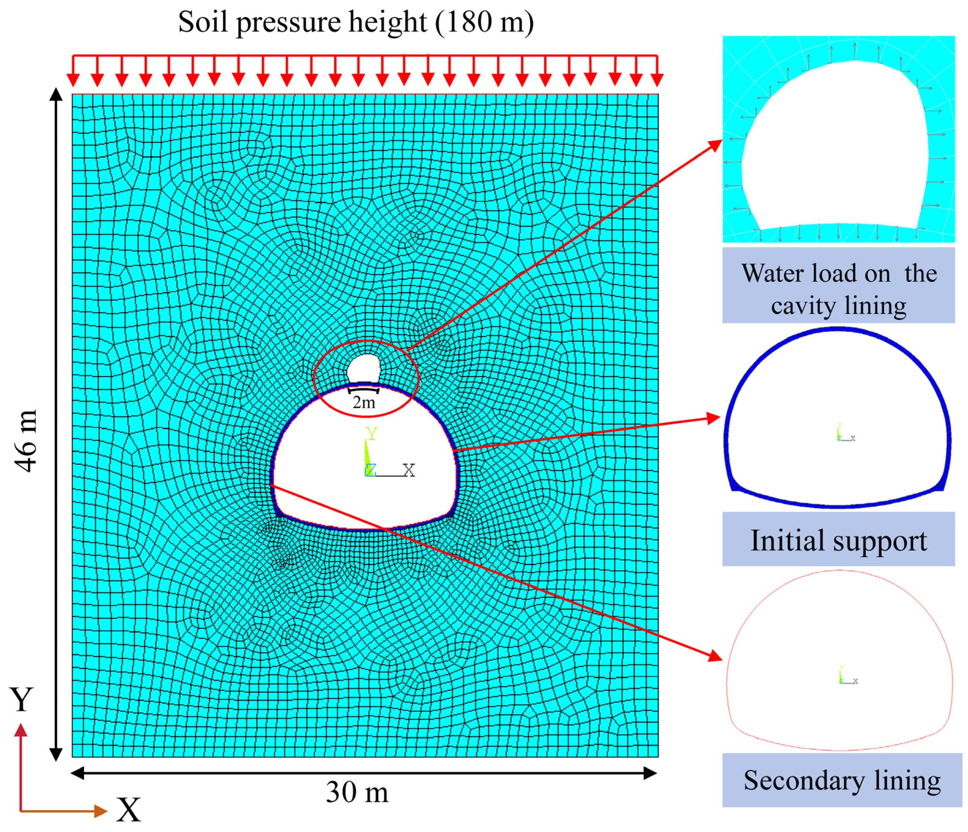
3.1. Numerical Model and Parameter Selection

This paper uses ANSYS (Version R15.0) software for calculation, and the model adopts a plane strain model. According to the actual on-site construction, the shallow buried section of the tunnel entrance has been completed, and no large karst cavity has been exposed. In addition, the potential water pressure of the shallow buried section of the tunnel is relatively small. In addition, the exposed karst section is mainly buried at a depth of 200–250 m. Therefore, a plane stratum structure model is established for the exposed karst section with a burial depth of 200 m in the model calculation. Considering that tunnel excavation has little effect on the stress distribution outside the 20 m overburden, only a 20 m solid model of the overburden is established in the model, and boundary stress is applied to simulate the ground stress field.
In order to eliminate the influence of the model boundary on the calculation results, the model size is set to 30 m × 46 m (width × height), in which the support material adopts an elastic constitutive model, the surrounding rock adopts an elasto-plastic constitutive model, and the failure criterion adopts the Mohr–Coulomb strength criterion. The PLANE42 is suitable for the surrounding rock and primary support, and Beam Element is suitable for the secondary lining. The top boundary of the model is the soil pressure height of 180 m. The left and right boundaries of the model limit its horizontal displacement, while the bottom boundary of the model limits both the horizontal and vertical displacements simultaneously. The model mesh adopts a quadrilateral mesh, and a certain amount of densification is carried out in the tunnel and cave areas. The maximum size of the model mesh is 0.8 m and the minimum size is 0.1 m. The specific details of the model are shown in Figure 2. The surrounding rock is classified into three grades (III, IV, and V), and the surrounding rock parameters in the model are selected according to the geological survey data. The support parameters are calculated according to the bending stiffness of the on-site water pressure lining parameters [4]. The details are shown in Table 2.
In the simulation, the tunnel structure is assumed to experience localized high water pressure during operation, which is applied after construction. The model loading process proceeds as follows:
(1)
Calculate the initial self-weight stress field.
(2)
Simulate tunnel excavation and stress release in karst areas to determine the ground stress field and structural stress characteristics upon completion.
(3)
Apply water pressure around the cavity boundary. An internal program calculates the pressure based on the designated water pressure height, and the corresponding nodal forces are then applied to the cavity boundary to simulate the water load.

3.2. Working Condition Design

The simulation primarily considers how cavity location, cavity size, water pressure height, and surrounding rock conditions affect the stress characteristics of tunnel structures in karst areas. Because the cavity is fed by a complex external pipeline system, it is challenging to evaluate the resulting water pressure solely based on cavity size. Therefore, cavity size is defined by the circumferential width of its contact with the structure.
As indicated by the data in Table 3, cavities were exposed in surrounding rock classified as grades III, IV, and V, with larger cavities typically found in the arch crown, arch spandrel, and side wall. Given that grouting effectively fills cavities less than 1 m in circumferential width, this study focuses on larger cavities that are difficult to fill. Consequently, cavity widths of 2 m and 3 m were selected for analysis. Finally, based on these parameters, different models were constructed, and the water pressure inside each cavity was gradually increased until the lining’s internal forces surpassed its ultimate bearing capacity.

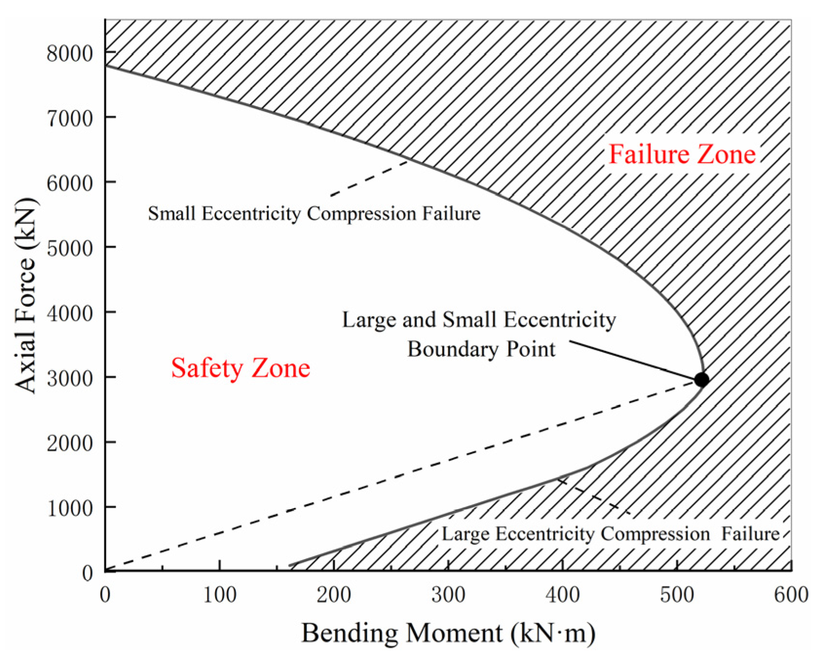
3.3. Structural Safety Assessment Methods

The primary material of the tunnel lining is reinforced concrete. The structure experiences bending moments, axial forces, and shear forces due to localized high water pressure. The failure modes of the concrete can be categorized into small eccentricity compression failure and larger eccentricity compression failure based on the design principles of reinforced concrete structures. To analyze the stress distribution pattern of the structure under karst water pressure, the simulation results are integrated with the recommended method [18] to identify the most vulnerable regions of the structure, which are defined as the stress characteristic points. Simultaneously, the bearing capacity envelope of the lining structure at the critical state of the concrete is calculated, as illustrated in Figure 3. If the stress state of the structural characteristic points lies within the bearing capacity envelope, the structure is deemed safe under the influence of karst water pressure at this level. Otherwise, it is considered unreliable [19].

4. Results Analysis

4.1. Structural Mechanical Response After Cavity Filling

Figure 4 and Figure 5 illustrate the distribution of structural axial force and bending moment under two conditions: absence of karst and the development of vault karst. To analyze the impact of water filling in the karst cavity on structural stress, the surrounding rock is classified as grade III, the circumferential width of the karst cavity is set to 2 m, and the water pressure head height is defined as 70 m.
As shown in Figure 4 and Figure 5, the water filling in the karst cavity significantly impacts the structural stress near the cavity, leading to a sharp increase in the axial force and bending moment of the secondary lining at the cavity’s midpoint, rising from 250 kN and 28 kN·m to 1140 kN and 252 kN·m, respectively. Based on the safety assessment method, the midpoint of the cavity is identified as the most critical position for the structure, and subsequent research will focus on this characteristic point. The breakdown and cracking of the secondary lining result from the combined effects of the surrounding rock, solution cavity, and water. This reveals the variation pattern of structural stress characteristics caused by changes in various factors, aiding in the safety evaluation of karst section structures [20].
Figure 6 illustrates the variation of internal forces in the structure at the midpoint of the solution cavity with changes in water pressure head height. This is analyzed under different surrounding rock conditions when the solution cavity is positioned at the arch crown, arch spandrel, and side wall, with corresponding circumferential widths of 2 m, 3 m, and 3 m, respectively. The pressure head increase gradient is set to 10 m for the arch crown and 5 m for the arch spandrel and side wall.
As shown in Figure 6, compared to the absence of karst development, a low water pressure head within the cavity results in the structural bearing state being farther from the strength envelope, indicating higher structural safety. This occurs because the structure lacks radial constraints at the karst cavity, causing the axial compression to induce outward bulging. However, the water pressure in the cavity counteracts this deformation by constraining it inward. At this stage, the structure primarily bears axial force, with a minimal bending moment.
As the water pressure within the cavity rises, the bending moment of the structure increases gradually, while the axial force decreases slightly. With increasing water pressure, the stress point of the structure gradually shifts toward the lower-right corner. This trend reduces the distance between the large eccentric compression state and the strength envelope, while increasing the distance for the small eccentric compression state.
At the point of structural failure, small eccentricity occurs when the grade IV and V surrounding rock arches expose the cavity, whereas large eccentricity dominates under other conditions. This indicates that when the grade IV and V surrounding rock arches expose the cavity, structural failure is initiated as the concrete reaches its pressure limit. In other conditions, the structural bearing capacity is primarily governed by the strength of the steel reinforcement.

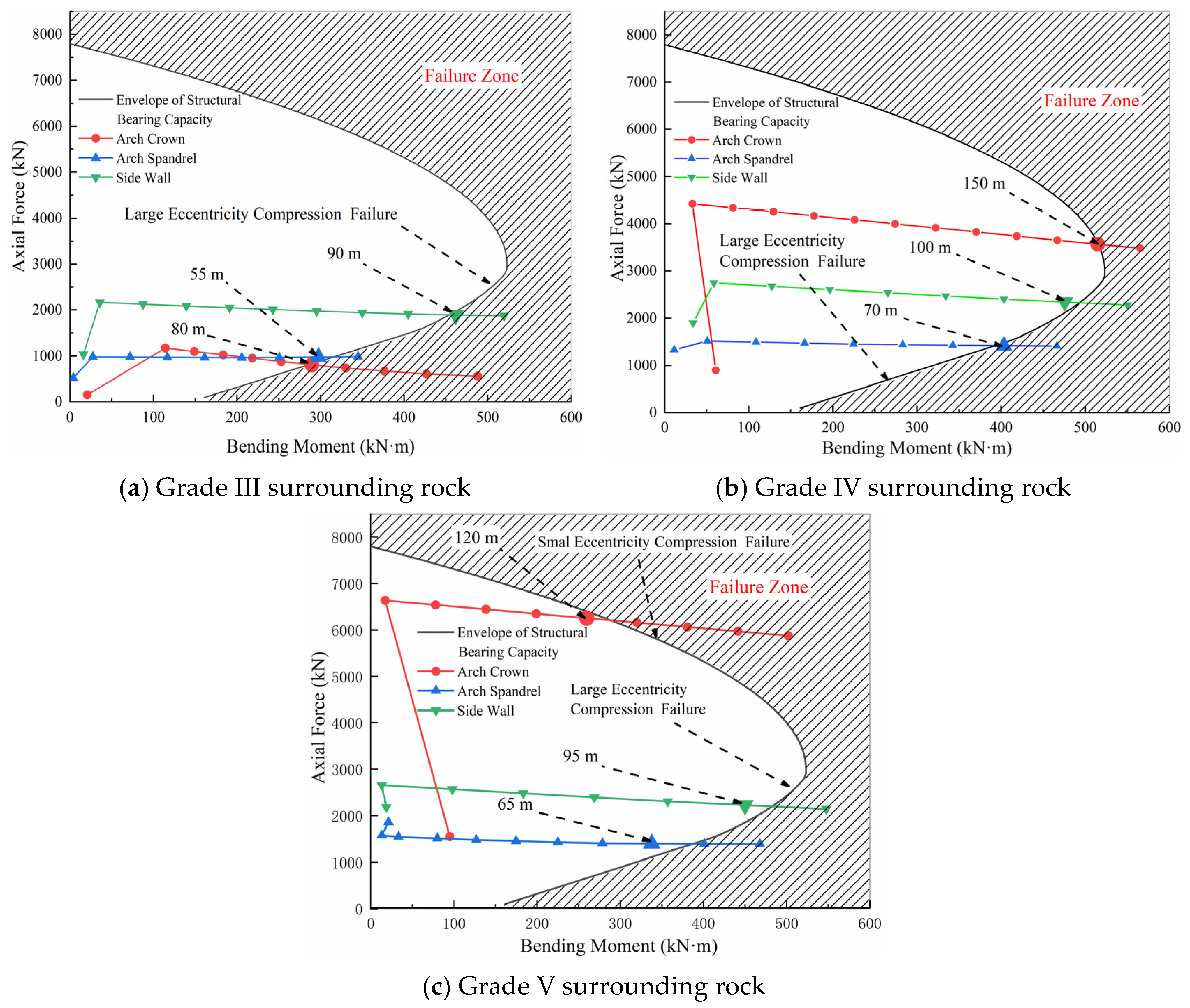
4.2. Influence of Surrounding Rock Grade on Structural Stress

As for underground engineering, surrounding rock acts both as a load source and as a constraint on structural deformation. The influence of karst cavities on structural performance varies depending on the surrounding rock conditions [21]. Based on the above analysis, the structural axial force exhibits minimal variation with increasing water pressure head. Therefore, the structural bending moment is primarily used to characterize the stress state of the structure. Figure 7 illustrates the relationship between the structural bending moment and water pressure head under varying surrounding rock grades.
By analyzing the bending moment states at structural characteristic points (e.g., arch crown, arch spandrel, and side wall) when karst cavities are exposed, the structural bending moment exhibits an approximately linear relationship with the water pressure head. The maximum bending moment occurs in grade III surrounding rock under the same water pressure head. This is because higher-quality surrounding rock provides stronger constraints on structural deformation. The location of the karst cavities serves as a weak point in the circumferential constraints imposed by the surrounding rock on the structure. Additionally, the structural coordination ability around the karst cavity is weakened under high water pressure. Therefore, under the same water pressure head, better physical and mechanical properties of the surrounding rock result in greater bending moments at the characteristic points. In grade IV and V rock masses, no distinct relationship between the bending moments is observed. This phenomenon may be attributed to groundwater pressure altering the surrounding stress field of the tunnel structure.
Figure 8 illustrates the critical water pressure that the structure can withstand when the cavity is exposed at the arch crown, arch spandrel, and side wall under various surrounding rock grades. As the quality of the surrounding rock improves, the critical water pressure that the structure can withstand initially increases and then decreases. The critical water pressure ensuring structural safety is highest in grade IV surrounding rock under identical conditions.
Using the critical water pressure height that the structure can withstand in grade III surrounding rock as a benchmark, the growth rates of the critical water pressure height at the crown in grade IV and V surrounding rock are 100% and 71.4%, respectively. The growth rates at the arch spandrel are 18.2% for both grade IV and V, while they are 17.6% and 11.8% at the side wall, respectively. Based on the variation in critical water pressure height, it is evident that surrounding rock conditions significantly impact structural safety when karst cavities are exposed at the crown.

4.3. Influence of Cavity Position on Structural Stress

Figure 8 illustrates the maximum karst water pressure that the structure can withstand when cavities are exposed at different locations. Among the three surrounding rock conditions, the structure exhibits the lowest critical water pressure head when the cavity is exposed at the arch spandrel, whereas the highest critical water pressure head occurs when the cavity is exposed at the arch crown in grade IV and V surrounding rock. In grade III surrounding rock, the most favorable condition for cavity exposure is at the side wall.
This phenomenon can be attributed to the following two factors. (a) When the cavity is exposed at the arch spandrel under water pressure, the structure is in an eccentric loading state. In contrast, when the cavity is exposed at the arch crown, the structure and its constraint system can still be approximated as symmetrical. As a result, the central region of the arch crown primarily bears the pressure, which is a key factor contributing to small eccentric failure in this area. (b) Compared to the side wall position, the surrounding rock and arch structure impose stronger constraints at both ends of the arch spandrel. Consequently, the load is less effectively transferred to other parts of the structure, leading to higher internal forces in the middle of the cavity.

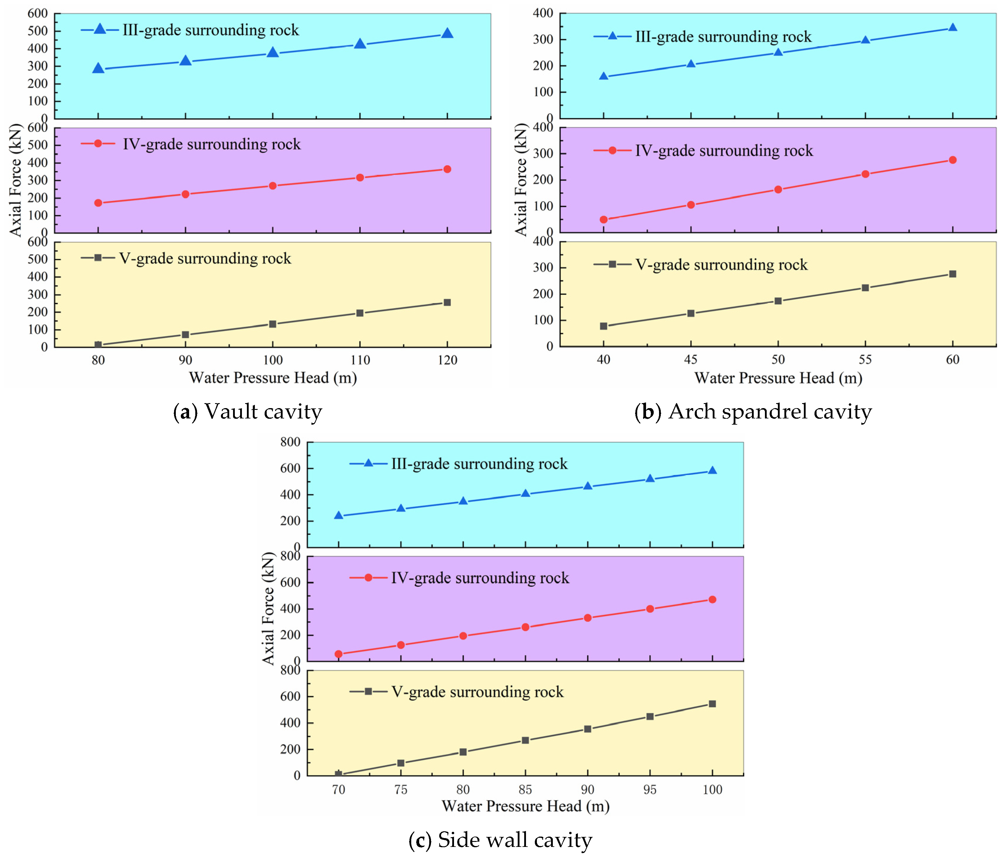
5. Critical Water Pressure Height of Structures Under Different Factors and Its Application

5.1. Determination of Critical Water Pressure Height and Failure Forms of Tunnels

Based on the above analysis, the maximum local water pressure head can be determined, and the corresponding concrete failure modes are presented in Table 4.
As shown in Table 4, the cross-sectional compression zone (concrete) fails first under small eccentric compression failure, and the steel bar in the cross-sectional tension zone contributes very little to resisting such damage. However, the cross-sectional tension zone (steel bar) fails first under large eccentric compression failure, and the concrete in the cross-sectional compression zone presents a ductile failure form. The large eccentric compression failure is the ideal destruction mode in design.
Therefore, to maximize material performance and optimize economic efficiency, priority should be given to enhancing concrete strength and increasing concrete thickness in cases of small eccentric failure. In cases of large eccentric failure, the lining reinforcement strategy should prioritize increasing the structural reinforcement ratio.

5.2. On-Site Tunnel Construction and Design Optimization Solutions

During the construction of the supporting tunnel project, the tunnel encountered six large-scale hollow karst caves, most of which contained mud and water. These caves extended toward blocked sinkholes at the bottom of the surface ditch and exhibited strong hydraulic connections with the drainage outlets of the underground river, acting as a primary source of karst springs. Overall, the minimum burial depth of the tunnel in karst section can reach up to 200 m. According to the results in Table 4, the maximum critical water pressure height under grade III, IV, and V surrounding rock conditions is 85 m, 140 m, and 120 m, respectively, so the actual applied maximum water pressure is significantly greater than the allowable value of the safety range under different surrounding rock conditions of the tunnel. Therefore, a safety assessment of the six large-scale karst caves in the tunnel is essential.
The safety evaluation of the six karst caves revealed in the limestone section of the tunnel was conducted based on the allowable safety thresholds under different surrounding rock conditions, as shown in Table 5.
As illustrated in Table 5, three karst caves have hydrodynamic connections, while the other caves are kept in a dry state. Thus, karst tunnel construction and drainage system improvement measures were proposed for three karst caves during the construction of the tunnel. Taking the section of the K65 + 310 karst cave as an example, detailed measures are introduced as follows.
Compared with the conventional construction of tunnels, the backfilling reinforcement and drainage measures have been added. Firstly, the support at the lining position and the base of the karst cavity is installed, and the pumped C30 underwater concrete is used to construct the arch. Secondly, the karst cave water is primarily drained; thus, two high-density polyethylene pipes with a diameter of 300 mm should be pre-buried to channel the karst water into the tunnel side wall maintenance pool during construction, from where it flows into the sedimentation pool beneath the road surface. Then, φ42 × 4 mm perforated steel flower pipes, each 6 m in length, are radially drilled within a radius of at least 3 m around the karst cavity, and the spacing is the same as the system anchor rods. Finally, ultra-fine cement grouting is used for the perforated steel flower pipes. Therefore, the above qualitative measures can significantly improve the drainage efficiency of groundwater, thus indirectly reducing the water pressure behind the tunnel lining under rainfall conditions compared with the conventional construction of tunnels.
Moreover, the most important quantitative measure is the reinforcement of the lining structure in karst areas to ensure the long-term stability of the lining structure under high water pressure conditions. In the original design, the maximum thickness of the secondary lining was 45 cm (SA5 lining structure), whereas it was increased to 65 cm (SA5JQB lining structure) in the karst cave section.
In the conventional section, the tunnel design adopts the SA3 and SA4 tunnel lining forms. However, the SA5 tunnel lining from the original design was replaced with the SA5JQB type based on the karst cave location in the karst reinforcement section. The local reinforcement details for the karst sections of the left and right tunnels are presented in Table 6.
By implementing construction treatments, drainage measures, and localized reinforcement for the lining structure in the karst section of the tunnel, the risk of structural failure due to localized high water pressure can be significantly reduced. Therefore, through the implementation of tunnel construction and design optimization measures, the structural safety of the tunnel can be ensured under heavy rainfall conditions.

6. Conclusions

This study focuses on the mechanical characteristics of a tunnel lining structure under varying surrounding rock conditions and karst water pressures, proposes the critical water pressure of the tunnel lining structure, evaluates the safety status of an actual karst tunnel, and proposes detailed tunnel optimization solutions. The main conclusions are as follows:
(1)
Compared with the absence of karst conditions, water filling in karst cavity will lead to a sharp increase in the internal forces of the structure. When the water pressure inside the cavity is relatively small, it can restrain the bulging deformation of the structure into the cavity, which is more beneficial to the structure. However, as the water pressure increases, the internal forces of the structure gradually increase until it is damaged.
(2)
When the water pressure is the same, the lining structure bears the greatest bending moment in the grade III surrounding rock under different position conditions of the karst cave. Due to the dual nature of the surrounding rock’s effect on the structure as both load and constraint, the critical water pressure of the structure increases first and then decreases with the increase in the surrounding rock grade.
(3)
In terms of structural failure forms, when karst develops at the arch top position in grade IV and V surrounding rocks, the structure is damaged in the form of small eccentric compression, while the remaining surrounding rock grades and cave location conditions are all damaged in the form of large eccentric compression.
(4)
Due to the force symmetry and constraints of the structure, the critical water pressure value of the lining structure at the arch shoulder position is the smallest under different surrounding rock grades and should be closely monitored.
(5)
A safety assessment was conducted based on critical water pressure values under various influencing factors. Accordingly, corresponding construction measures were applied to improve the drainage efficiency of groundwater, and the thickness of the secondary lining was increased to improve the structural stability of the karst tunnel. Thus, the safety of karst tunnels can be guaranteed under heavy rainfall conditions.
(6)
In the future, the rationality of the critical water pressure height proposed in this paper will be explored through the method of indoor experiments. Meanwhile, research on the mechanical characteristics of the lining structure under the coupling effect of surrounding rock and groundwater is being further explored.

Author Contributions

Conceptualization, W.Q. and X.W.; Formal analysis, X.M.; Investigation, W.Q., X.M. and X.W.; Resources, W.Q.; Writing—original draft, X.T. and X.M.; Writing—review & editing, X.W.; Visualization, X.T.; Supervision, W.Q. and X.W.; Funding acquisition, W.Q. All authors have read and agreed to the published version of the manuscript.

Funding

This work was supported by the National Key Research and Development Program of China (Grant No. 2024YFF0507903), the National Natural Science Foundation of China (Grant No. 52208395), and the Natural Science Foundation of Jiangsu Province (Grant No. BK20240942).

Data Availability Statement

The datasets used and analyzed during the current study are available from the corresponding author on reasonable request.

Conflicts of Interest

The authors declare no conflicts of interest.

Nomenclature

PLANE42A planar element in the ANSYS element library
C20The designed compressive strength of concrete is 20 MPa
C30The designed compressive strength of concrete is 30 MPa
SA3The secondary lining form of surrounding rock III
SA4The secondary lining form of surrounding rock IV
SA5The secondary lining form of surrounding rock V
SA5JQBThe secondary lining form of surrounding rock V in the reinforcement section

References

  1. Huang, K.; Ma, Z.; Wang, X.; Shan, J.; Zhang, Z.; Xia, P.; Jiang, X.; Wu, X.; Huang, X. Control of soil organic carbon under karst landforms: A case study of Guizhou Province, in southwest China. Ecol. Indic. 2022, 145, 109624. [Google Scholar] [CrossRef]
  2. Jin, M.; Liu, X.; Zhong, Z. Study on the Mechanical Characteristics of the Lining Structure of the Karst Tunnel under the Action of Local High Water Pressure on the Vault. Chin. J. Undergr. Space Eng. 2021, 17, 1099–1105+1131. [Google Scholar]
  3. Li, T.; Zhang, L.; Jiang, Q.; Feng, C.; Zhao, R. Safe Thickness and Fracture Evolution Law Determined for Hydraulic Fracturing of Water-Resistant Rock Mass with Hidden Karst Based on GDEM. Tunn. Constr. 2021, 41, 67–76. [Google Scholar]
  4. Qian, W.; Wang, B.; Luo, D.; Xu, A.; Li, S. Experimental investigation and application on mechanical properties of tunnel linings under different blockage rates of drainage system in a karst tunnel. Tunn. Undergr. Space Technol. 2025, 157, 106359. [Google Scholar] [CrossRef]
  5. Yuan, B.; Liang, J.; Zhang, B.; Chen, W.; Huang, X.; Huang, Q.; Li, Y.; Yuan, P. Optimized reinforcement of granite residual soil via a cement and alkaline solution: A coupling effect. J. Rock Mech. Geotech. Eng. 2025, 17, 509–523. [Google Scholar] [CrossRef]
  6. Wang, J.; Lin, G. Study on the Characteristics of Secondary Lining Cracking under the Effect of Rheological Load. Mod. Tunn. Technol. 2020, 57, 83–90. [Google Scholar]
  7. Wan, F.; Li, K.; Wang, H.; Zhang, X. Analysis of Mechanical Characteristics of Karst Tunnel Lining Structure Under Heavy Rainfall. China J. Highw. Transp. 2023, 36, 312–322. [Google Scholar]
  8. Ding, W.; Liu, Y.; Wang, W.; Zhou, Y.; Li, H.; Rui, Y. Dynamic Risk Assessment of Water Inrush and Mud Burst in Tunnels Based on Fuzzy Two-dimensional Cloud Probability Model. Mod. Tunn. Technol. 2024, 61, 261–268. [Google Scholar]
  9. Sun, X.; Guo, X.; Si, N. Effects of Pipe-Type Hidden Caverns on Tunnel Lining Structure Under Strong Rainfall Conditions. Tunn. Constr. 2023, 43, 1831–1841. [Google Scholar]
  10. Bai, C. Research on Intelligent Prediction Method of Hazard Risk of Water and Mud inrush in Karst Tunnel Based on Machine Learning. Ph.D. Thesis, Shandong University, Jinan, China, 2021. [Google Scholar]
  11. Yu, H. Discussion on lining strength of railway tunnels in karst areas under instantaneous heavy rainfall: An example of the Yuanbaoshan tunnel of Zhijin-Bijie railway in Guizhou Province. Carsilogica Sin. 2019, 38, 916–923. [Google Scholar]
  12. Shang, H.; Zhen, B.; Guo, R. Structural Mechanical Response Caused by Water Pressure Change of Karst Water-rich Tunnel and Prevention Measures. Mod. Tunn. Technol. 2020, 57, 374–381. [Google Scholar]
  13. Yuan, Y. Design of Railway Tunnel Drainage Tunnel in the Stratum with Large Water Volume in the Karst Area with Large Depth. Chin. J. Undergr. Space Eng. 2021, 17, 834–839. [Google Scholar]
  14. Xu, Q.; Song, Y.; Fan, H.; Tan, X.; Yang, H. Model Test Study on Water Pressure Distribution Characteristics of Lining Structure in Water-Rich Karst Tunnel. China Railw. Sci. 2022, 43, 74–83. [Google Scholar]
  15. Bao, T.; Zhang, S.; Liu, C.; Xu, Q. Experimental Study on the Effect of Hydraulic Deterioration of Different Drainage Systems on Lining Water Pressure. Processes 2022, 10, 1975. [Google Scholar] [CrossRef]
  16. Zhang, C.; Liu, N.; Chen, K.; Ren, F. Study on drainage mode and anti-clogging performance of new waterproofing and drainage system in a tunnel. Sci. Rep. 2023, 13, 5354. [Google Scholar] [CrossRef] [PubMed]
  17. Teng, Z.; Liu, Y.; Zhou, Y.; Li, Y.; Mei, S.; Chen, Q.; Chen, L.; Du, B. Investigation of a new reverse drainage construction and the pressure-reducing effect of a tunnel in a water-rich karst location. Tunn. Undergr. Space Technol. 2024, 145, 105580. [Google Scholar] [CrossRef]
  18. Luo, Y.; Yang, J.; Xie, Y.; Fu, J.; Zhang, C. Investigation on evolution mechanism and treatment of invert damage in operating railway tunnels under heavy rainfall. Bull. Eng. Geol. Environ. 2024, 83, 160. [Google Scholar] [CrossRef]
  19. Yang, C.; Cui, Z.; Niu, F.; Wang, B. Influence Mechanism on Structural Safety by Tunnel Liner Diseases. J. Water Resour. Archit. Eng. 2023, 21, 180–186. [Google Scholar]
  20. Liu, H. The Interaction between Karst Cave Water Storage and Tunnel Lining in Complex Karst Area. Sci. Technol. Eng. 2020, 20, 9140–9148. [Google Scholar]
  21. Zheng, Y.; Abil, D. On Stability Analysis and Classification of Surrounding Rocks in Rock Tunnels. Mod. Tunn. Technol. 2022, 59, 1–13. [Google Scholar]
Figure 1. Schematic diagram of the composite lining.
Buildings 15 01756 g001
Figure 2. Schematic diagram of calculation model.
Buildings 15 01756 g002
Figure 3. Envelope of structural bearing capacity.
Buildings 15 01756 g003
Figure 4. Mechanical characteristics of the tunnel lining with no karst.
Buildings 15 01756 g004
Figure 5. Mechanical characteristics of the tunnel lining with karst development in vault.
Buildings 15 01756 g005
Figure 6. Structural stress characteristic variation curve.
Buildings 15 01756 g006
Figure 7. Curve of bending moment changed with water pressure height.
Buildings 15 01756 g007
Figure 8. Variation diagram of critical water pressure under different rock grades and different locations.
Buildings 15 01756 g008
Table 1. The locations and exposure details of the cavities.
Cavity LocationCircumferential Width of CavityQuantity
Arch crown<1 m3
1 m~2 m2
2 m~3 m0
Arch spandrel<1 m4
1 m~2 m3
2 m~3 m2
Side wall<1 m4
1 m~2 m3
2 m~3 m1
Table 2. Unit types and mechanical parameters of different materials.
MaterialElement TypeElastic Modulus
(GPa)
Poisson’s RatioDensity
(kg·m−3)
Cohesion
(MPa)
Internal Friction Angle (°)
Primary supportPLANE4228.00.22200\\
Secondary liningBeam Element30.00.22300\\
Surrounding rock IIIPLANE4212.00.252500140
Surrounding rock IVPLANE423.00.3223000.530
Surrounding rock VPLANE421.20.3820000.1424
Table 3. Simulated working conditions.
Influencing FactorsWorking Condition DesignRemarks
Cavity locationArch crownCircumferential width: 2 m, 3 m
Arch spandrelCircumferential width: 2 m, 3 m
Side wallCircumferential width: 2 m, 3 m
Water pressure height0 m-ultimate water pressure height/
Surrounding rock gradeIII/
IV/
V/
Table 4. Critical water pressure height and failure modes under various working conditions.
Surrounding Rock GradeCircumferential Width of Cavity (m)Location of CavityCritical Water Pressure Height (m)Destruction Mode
III2Arch crown70Large eccentric compression failure
Arch spandrel65
Side wall70
3Arch crown60
Arch spandrel55
Side wall85
IV2Arch crown140Small eccentric compression failure
Arch spandrel80Large eccentric compression failure
Side wall85
3Arch crown90
Arch spandrel65
Side wall100
V2Arch crown120Small eccentric compression failure
Arch spandrel85Large eccentric compression failure
Side wall105
3Arch crown85
Arch spandrel65
Side wall95
Table 5. Safety evaluation of six caves in the tunnel.
NumberLocation and SizeSurrounding Rock GradeOriginal Support TypeHave a Hydraulic Connection or NotSafe or NotNeed to Change the Design or Not
K65 + 372Arch spandrel, diameter 2 mIVSA4NoSafeUnnecessary
K65 + 327Arch waist, diameter 2 mVSA5NoSafeUnnecessary
K65 + 324Arch waist, diameter 6 mVSA5YesUnsafeNecessary
K65 + 310Arch waist, diameter 3 mVSA5YesUnsafeNecessary
ZK65 + 314Arch waist, diameter 3 mVSA5YesUnsafeNecessary
ZK65 + 240Arch spandrel, diameter 4 mIIISA3NoSafeUnnecessary
Table 6. Local reinforcement sections of karst areas of the tunnel.
Tunnel LocationConventional SectionStrengthening SectionConventional Section
Left TunnelOriginal designSA3 (130 m)SA5: ZK65 + 270~ZK65 + 330 (60 m)SA4 (100 m)
Design after changeSA3 (130 m)SA5JQB: ZK65 + 270~ZK65 + 330 (60 m)SA4 (100 m)
Right TunnelOriginal designSA3 (140 m)SA5: K65 + 290~K65 + 350 (60 m)SA4 (100 m)
Design after changeSA3 (140 m)SA5JQB: K65 + 290~K65 + 350 (60 m)SA4 (100 m)
Disclaimer/Publisher’s Note: The statements, opinions and data contained in all publications are solely those of the individual author(s) and contributor(s) and not of MDPI and/or the editor(s). MDPI and/or the editor(s) disclaim responsibility for any injury to people or property resulting from any ideas, methods, instructions or products referred to in the content.

