The Impact of Stray Currents on Chloride Transport in the Concrete of Urban Rail Transit Structures

Abstract
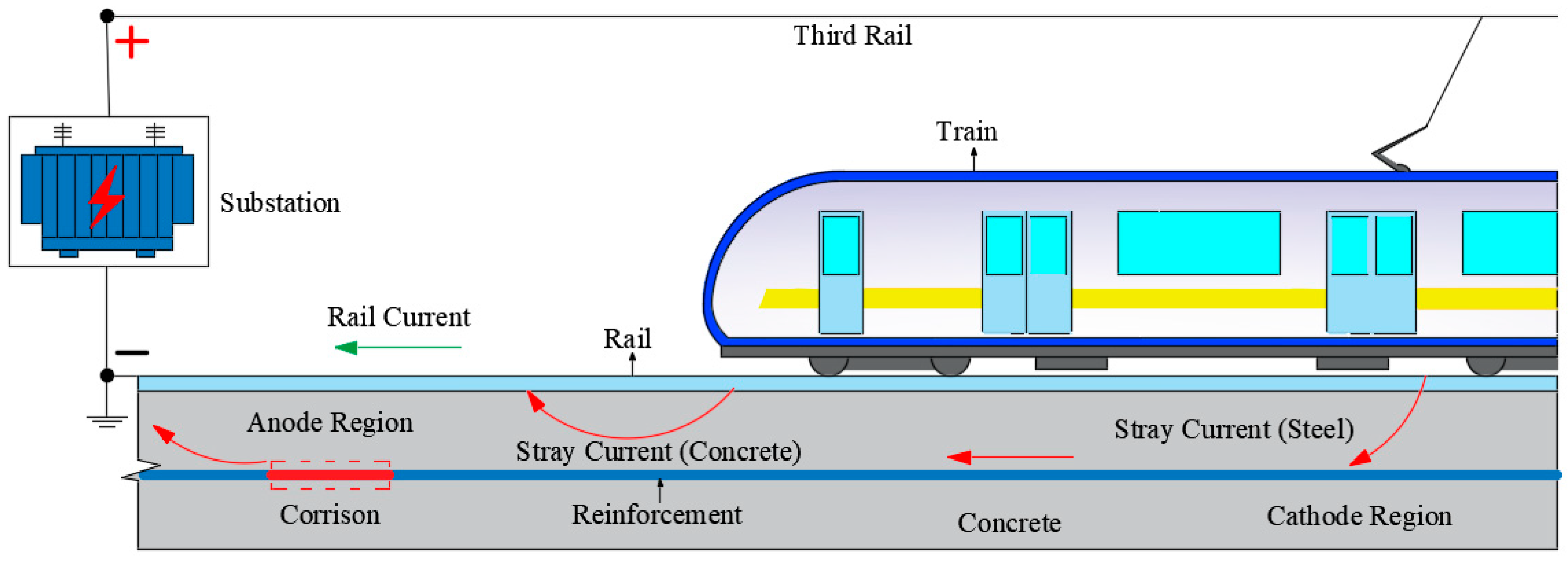
1. Introduction
2. Materials and Methods
2.1. Materials and Specimens
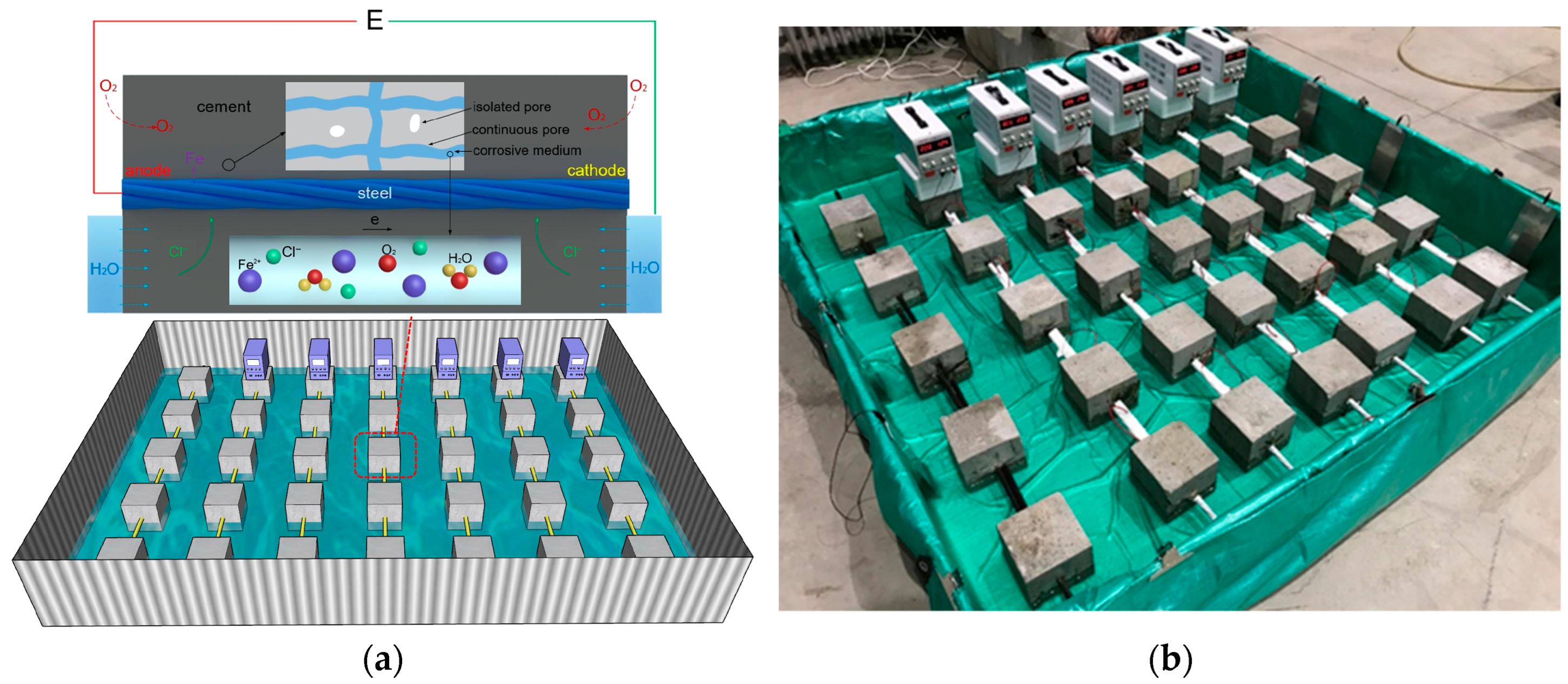
2.2. Experimental Setup
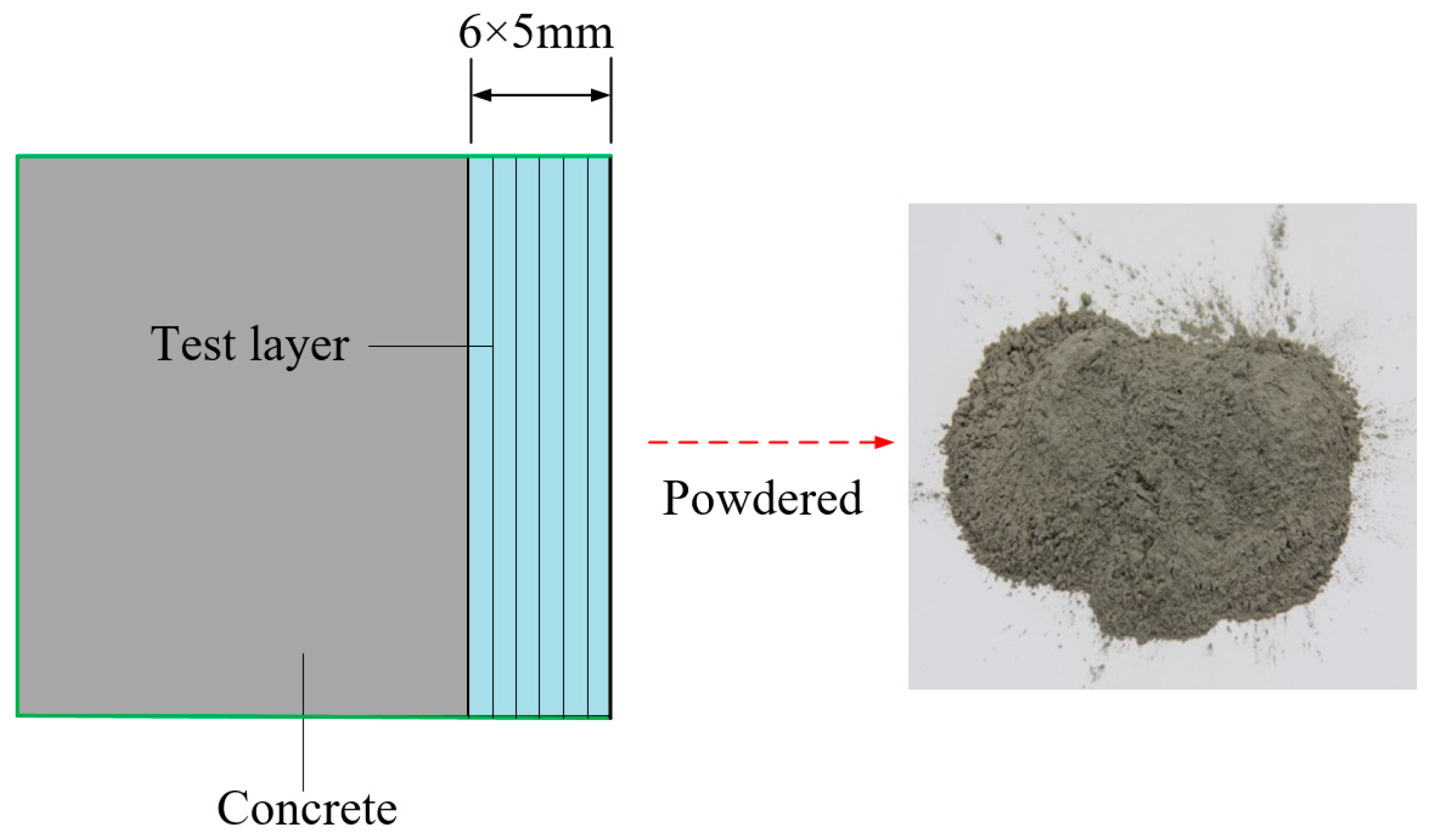
2.3. Chloride Measurement
2.4. Mercury Intrusion Porosimetry (MIP)
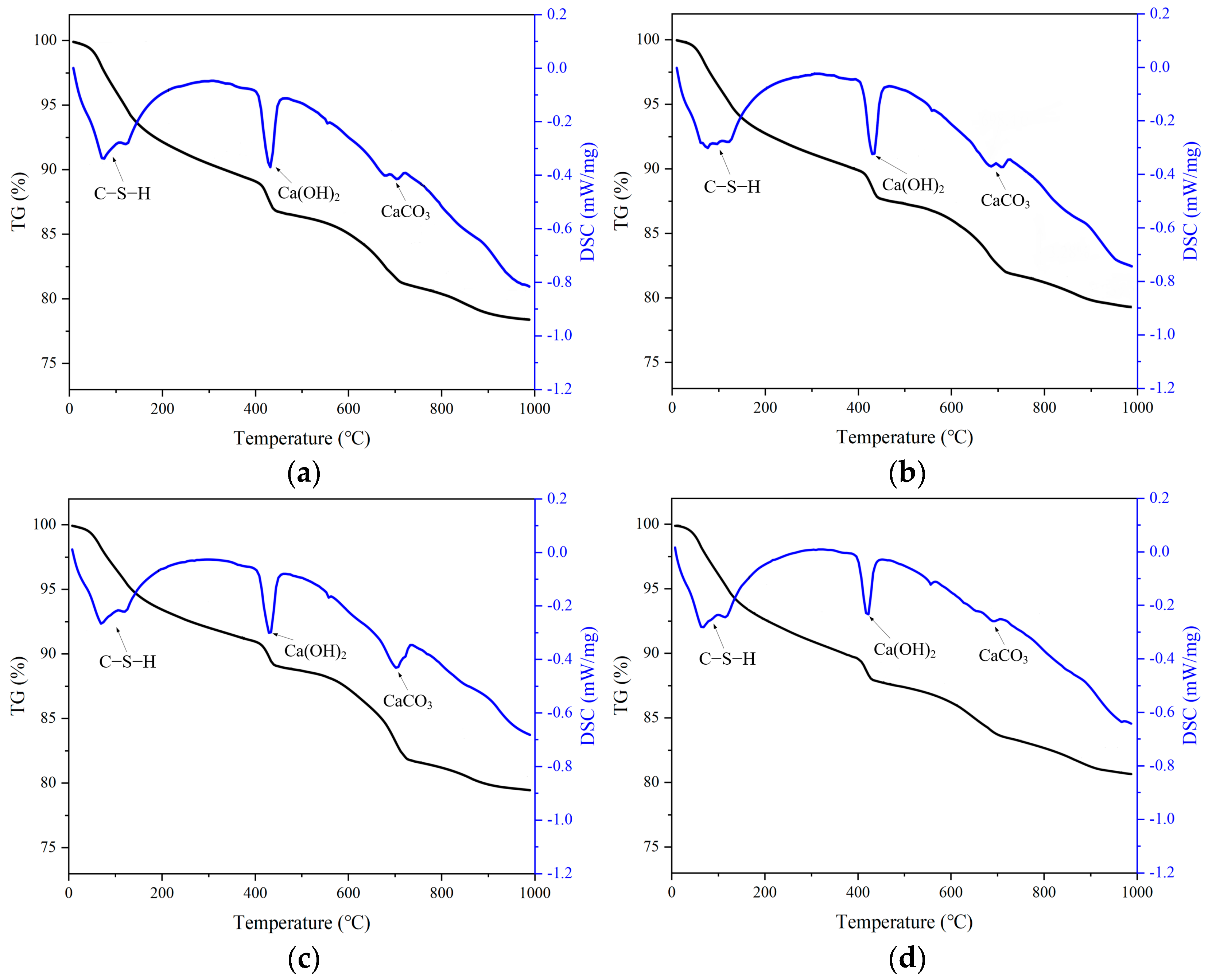
2.5. Thermal Gravimetric (TG) and Differential Scanning Calorimetry (DSC) Analysis
3. Results and Discussion
3.1. The Influence of Stray Currents on Cement Hydration Products
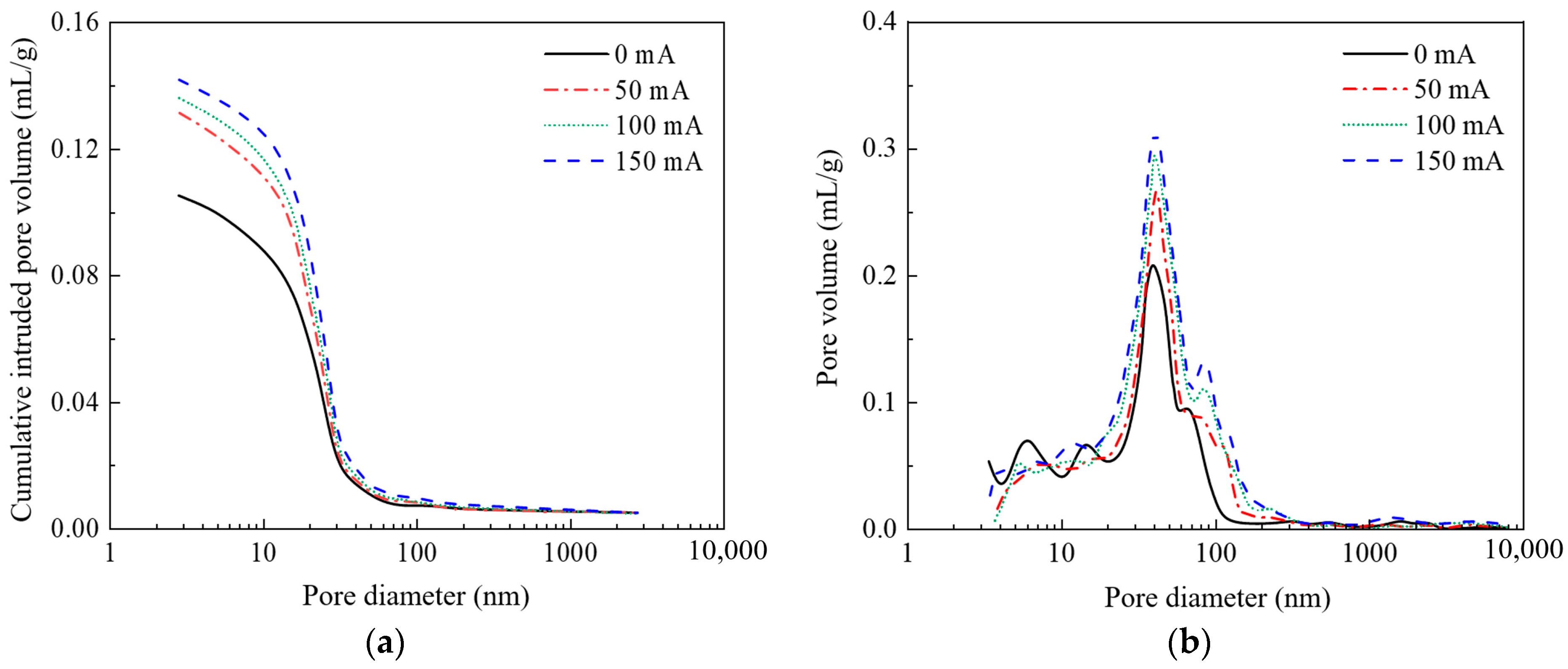
3.2. The Influence of Stray Currents on the Pore Structure of Concrete
3.2.1. Current Intensity
3.2.2. Current Time
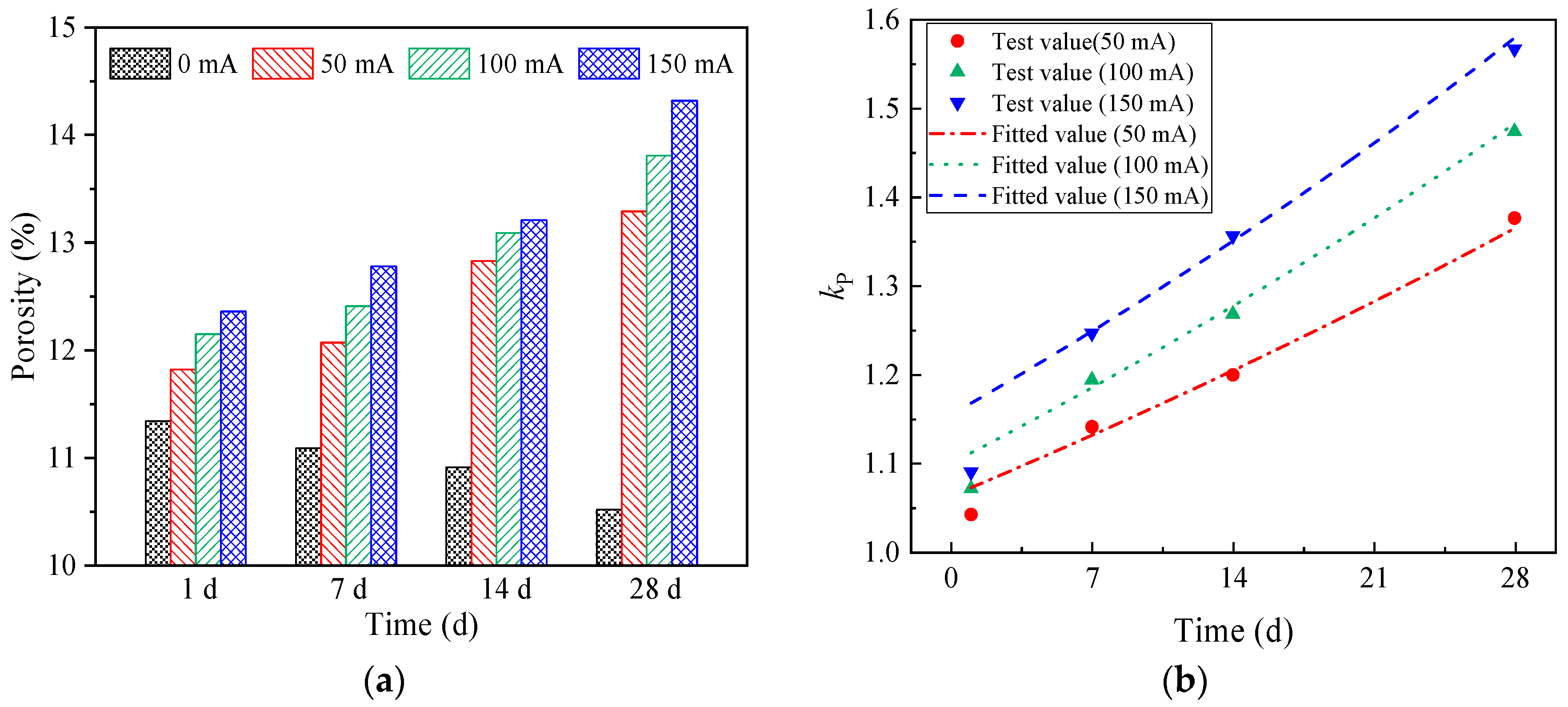
3.2.3. The Influence of Stray Currents on the Porosity of Concrete
3.3. The Influence of Stray Currents on Chloride Transport in Concrete
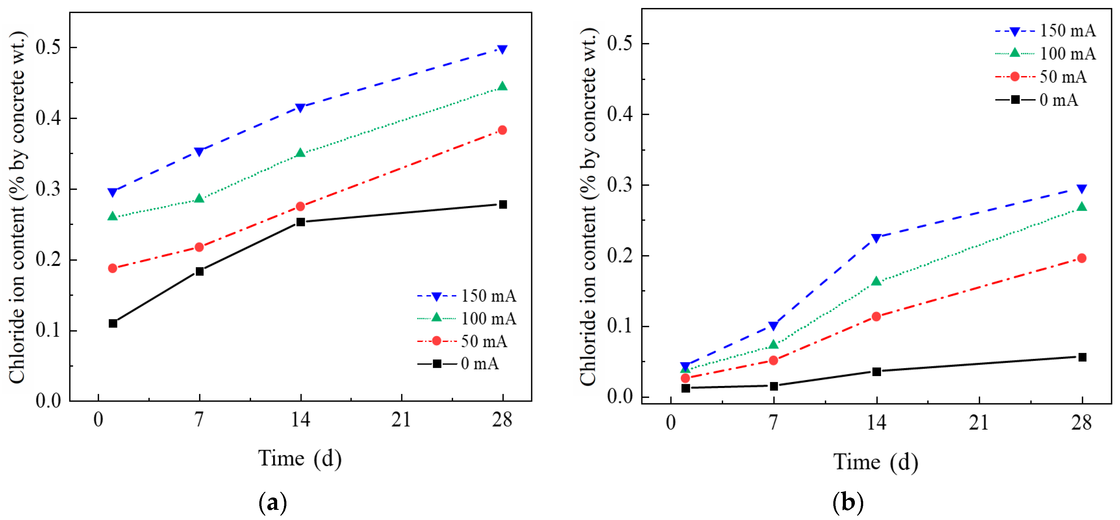
3.3.1. Chloride Ion Concentration Distribution in Concrete Under Stray Current
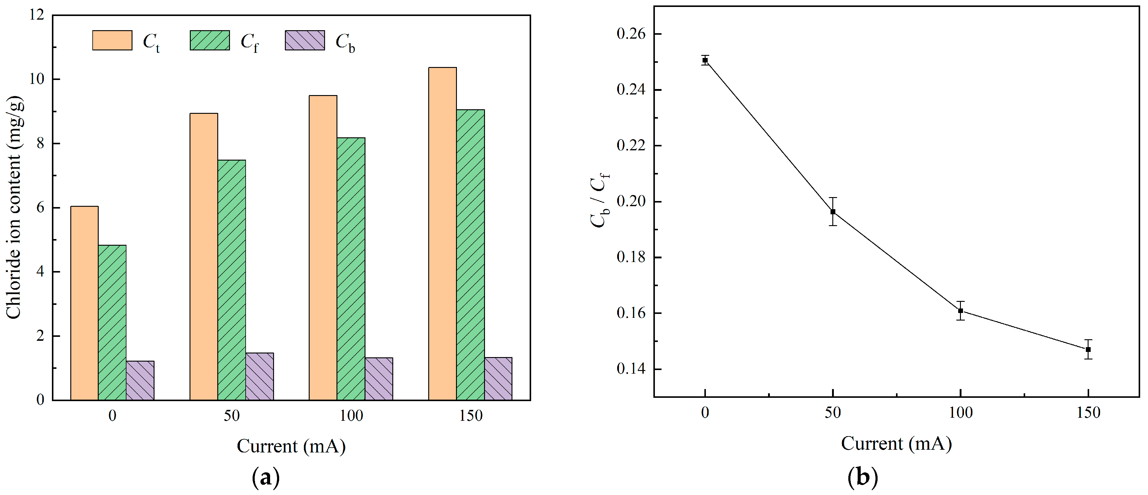
3.3.2. The Ability of Concrete to Bind Chloride Ions Under Stray Currents
3.4. Measures to Inhibit the Corrosion of Structure by Stray Current
3.4.1. Surface Coating
3.4.2. Electrochemical Treatment
3.4.3. High-Resistance Concrete
4. Conclusions
- (1)
- Stray current causes the accelerated precipitation of calcium ions in concrete. This is primarily attributed to the stray current, which induces the accumulation of chloride ions near the steel surface, leading to the faster decomposition of Ca(OH)2 the maintenance of ionic balance.
- (2)
- Stray currents lead to an increase in the porosity of concrete. In our study, under the same current time (28 days), the porosity of concrete specimens with different currents (0 mA, 50 mA, 100 mA, and 150 mA) were 10.52%, 13.29%, 13.81%, and 14.32%, respectively. Under the same current (150 mA), the porosity of concrete specimens with different current times (0 d, 7 d, 14 d, and 28 d) were 11.36%, 12.78%, 13.21%, and 14.32%, respectively. As the electrification time increases, the influence of stray currents on porosity becomes more significant.
- (3)
- Stray currents change the distribution of chloride ions in concrete. The chloride ion concentration of the concrete on the surface of the specimen (2 mm away from the exposed surface) gradually increases with time. In the early stage of the experiment (0–7 days), the increase in chloride ion concentration at the surface layer of the unelectrified specimen over time is even higher than the electrified specimen. Subsequently (14–28 days), the increase in the chloride ion content on the surface of the unelectrified specimen gradually slows down. The chloride ion content of the electrified specimen increases to a certain extent over time.
- (4)
- A stray current weakens the stability of bound chlorides in concrete. For the specimens under currents (0 mA, 50 mA, 100 mA, and 150 mA), the values of their chloride ion binding capacity coefficients α are 0.2455, 0.1964, 0.1609, and 0.1470, respectively. As the current intensity increases, the chloride ion content continues to increase, and the increase in free-state chloride ions is higher than that of cured-state chloride ions. The ability of concrete to bind chloride ions gradually weakens with the increase in the stray current.
Author Contributions
Funding
Data Availability Statement
Conflicts of Interest
References
- Brichau, F.; Deconinck, J.; Driesens, T. Modeling of Underground Cathodic Protection Stray Currents. Corrosion 2006, 52, 480–488. [Google Scholar] [CrossRef]
- Solgaard, A.O.S.; Carsana, M.; Geiker, M.R.; Küter, A.; Bertolini, L. Experimental Observations of Stray Current Effects on Steel Fibres Embedded in Mortar. Corros. Sci. 2013, 74, 1–12. [Google Scholar] [CrossRef]
- Hong, Y.; Li, Z.; Qiao, G.; Ou, J. Numerical Simulation and Experimental Investigation of the Stray Current Corrosion of Viaducts in the High-Speed Rail Transit System. Constr. Build. Mater. 2017, 157, 416–423. [Google Scholar] [CrossRef]
- Alamuti, M.M.; Nouri, H.; Jamali, S. Effects of Earthing Systems on Stray Current for Corrosion and Safety Behaviour in Practical Metro Systems. IET Electr. Syst. Transp. 2011, 1, 69–79. [Google Scholar] [CrossRef]
- Dolara, A.; Foiadelli, F.; Leva, S. Stray Current Effects Mitigation in Subway Tunnels. IEEE Trans. Power Deliv. 2012, 27, 2304–2311. [Google Scholar] [CrossRef]
- Umar, K.M.; Shamsad, A.; Jubran, A.G.H. Chloride-Induced Corrosion of Steel in Concrete: An Overview on Chloride Diffusion and Prediction of Corrosion Initiation Time. Int. J. Corros. 2017, 2017, 1–9. [Google Scholar]
- Goudar, S.K.; Das, B.B.; Arya, S.B.; Shivaprasad, K.N. Influence of Sample Preparation Techniques on Microstructure and Nano-Mechanical Properties of Steel-Concrete Interface. Constr. Build. Mater. 2020, 256, 119242. [Google Scholar] [CrossRef]
- Liu, G.; Zhang, Y.; Ni, Z.; Huang, R. Corrosion Behavior of Steel Submitted to Chloride and Sulphate Ions in Simulated Concrete Pore Solution. Constr. Build. Mater. 2016, 115, 1–5. [Google Scholar] [CrossRef]
- Deqi, Z.; Aihua, W.; Dianrui, M.; Aiping, T.; Lin, J.; Wenchuan, Y. Investigation into Compressive Property, Chloride Ion Permeability, and Pore Fractal Characteristics of the Cement Mortar Incorporated with Zeolite Powder. Constr. Build. Mater. 2024, 411, 134522. [Google Scholar]
- Xia, J.; Li, L. Numerical Simulation of Ionic Transport in Cement Paste under the Action of Externally Applied Electric Field. Constr. Build. Mater. 2013, 39, 51–59. [Google Scholar] [CrossRef]
- Beggs, J. Stray Current Testing on Gas Distribution Piping Following Start-up of a New Light Rail Transit Line. Mater. Perform. 2005, 44, 22–25. [Google Scholar] [CrossRef]
- Srikanth, S.; Sankaranarayanan, T.S.N.; Gopalakrishna, K.; Narasimhan, B.R.V.; Das, T.V.K.; Das, S.K. Corrosion in a Buried Pressurised Water Pipeline. Eng. Fail. Anal. 2004, 12, 634–651. [Google Scholar] [CrossRef]
- Wang, C.; Li, W.; Wang, Y.; Xu, S.; Yang, X. Chloride-Induced Stray Current Corrosion of Q235A Steel and Prediction Model. Constr. Build. Mater. 2019, 219, 164–175. [Google Scholar] [CrossRef]
- Masuda, Y.; Wu, F.-R.; Nakamura, S.; Sato, S. Penetration Behavior of Chloride Ions into Concrete in Coastal Areas. Key Eng. Mater. 2005, 533, 584–590. [Google Scholar]
- Bertolini, L.; Carsana, M.; Pedeferri, P. Corrosion Behaviour of Steel in Concrete in the Presence of Stray Current. Corros. Sci. 2006, 49, 1056–1068. [Google Scholar] [CrossRef]
- Chen, Z.; Dessi, K.; van Breugel, K. A Review on Stray Current-Induced Steel Corrosion in Infrastructure. Corros. Rev. 2017, 35, 397–423. [Google Scholar] [CrossRef]
- Brenna, A.; Beretta, S.; Bolzoni, F.; Pedeferri, M.; Ormellese, M. Effects of AC-Interference on Chloride-Induced Corrosion of Reinforced Concrete. Constr. Build. Mater. 2017, 137, 76–84. [Google Scholar] [CrossRef]
- Tang, K. Stray Current Induced Corrosion of Steel Fibre Reinforced Concrete. Cem. Concr. Res. 2017, 100, 445–456. [Google Scholar] [CrossRef]
- Hernández, F.C.R.; Plascencia, G.; Koch, K. Rail Base Corrosion Problem for North American Transit Systems. Eng. Fail. Anal. 2008, 16, 281–294. [Google Scholar] [CrossRef]
- Sánchez, I.; Nóvoa, R. Microstructural Modifications in Portland Cement Concrete Due to Forced Ionic Migration Tests. Study by Impedance Spectroscopy. Cem. Concr. Res. 2008, 38, 1015–1025. [Google Scholar] [CrossRef]
- Yin, G.; Tang, Y.; Wen, X.; Shao, J.; Feng, L.; Zuo, X. Effect of Calcium Leaching on the Characteristics of Chloride Physical Adsorption and Chemical Binding of Cement-Based Materials. Mater. Today Commun. 2023, 36, 106715. [Google Scholar] [CrossRef]
- Chen, X.; He, Y.; Lu, L.; Wang, F.; Hu, S. Effects of Curing Regimes on the Chloride Binding Capacity of Cementitious Materials. Constr. Build. Mater. 2022, 342, 127929. [Google Scholar] [CrossRef]
- Liu, Q.; Shen, X.; Šavija, B.; Meng, Z.; Tsang, D.C.W.; Sepasgozar, S.; Schlangen, E. Numerical Study of Interactive Ingress of Calcium Leaching, Chloride Transport and Multi-Ions Coupling in Concrete. Cem. Concr. Res. 2023, 165, 107072. [Google Scholar] [CrossRef]
- Bahman-Zadeh, F.; Zolfagharnasab, A.; Pourebrahimi, M.; Mirabrishami, M.; Ramezanianpour, A.A. Thermodynamic and Experimental Study on Chloride Binding of Limestone Containing Concrete in Sulfate-Chloride Solution. J. Build. Eng. 2023, 66, 105940. [Google Scholar] [CrossRef]
- Zhu, X.; Peng, W.; Xiao, C.; Ma, L.; Hou, J. Effect of Electric Field Intensity on Chloride Binding Capacity of Concrete. J. Mater. Res. Technol. 2023, 23, 4466–4478. [Google Scholar] [CrossRef]
- Jiang, Z.; Pan, Y.; Lu, J.; Wang, Y. Pore Structure Characterization of Cement Paste by Different Experimental Methods and Its Influence on Permeability Evaluation. Cem. Concr. Res. 2022, 159, 106892. [Google Scholar] [CrossRef]
- Ding, Z.; Quy, N.; Noguchi, T.; Kim, J.; Hama, Y. A Study on the Change in Frost Resistance and Pore Structure of Concrete Containing Blast Furnace Slag under the Carbonation Conditions. Constr. Build. Mater. 2022, 331, 127295. [Google Scholar] [CrossRef]
- Wang, L.; Jin, M.; Guo, F.; Wang, Y.; Tang, S. Pore Structural and Fractal Analysis of the Influence of Fly Ash and Silica Fume on the Mechanical Property and Abrasion Resistance of Concrete. Fractals 2021, 29, 2140003. [Google Scholar] [CrossRef]
- Huang, J.; Niu, D.; Lv, Y.; Li, Z. Deterioration Mechanism and Pore Structure Characteristics of Concrete under the Coupling Effect of SO2 and CO2. J. Build. Eng. 2025, 100, 111760. [Google Scholar] [CrossRef]
- Guo, Y.; Chen, X.; Chen, B.; Wen, R.; Wu, P. Analysis of Foamed Concrete Pore Structure of Railway Roadbed Based on X-Ray Computed Tomography. Constr. Build. Mater. 2021, 273, 121773. [Google Scholar] [CrossRef]
- Charalambous, C.A.; Aylott, P.; Buxton, D. Stray Current Calculation and Monitoring in DC Mass-Transit Systems: Interpreting Calculations for Real-Life Conditions and Determining Appropriate Safety Margins. IEEE Veh. Technol. Mag. 2016, 11, 24–31. [Google Scholar] [CrossRef]
- Lucca, G. Estimating Stray Current Interference from DC Traction Lines on Buried Pipelines by Means of a Monte Carlo Algorithm. Electr. Eng. 2015, 97, 277–286. [Google Scholar] [CrossRef]
- JTS/T 236-2019; Technical Specifications for Concrete Testing and Inspection in Water Transport Engineering. China Communications Press: Beijing, China, 2019.
- ASTM D4404-10; Standard Test Method for Determination of Pore Volume and Pore Volume Distribution of Soil and Rock by Mercury Intrusion Porosimetry. ASTM International: West Conshohocken, PA, USA, 2010.
- Ma, H. Mercury Intrusion Porosimetry in Concrete Technology: Tips in Measurement, Pore Structure Parameter Acquisition and Application. J. Porous Mater. 2014, 21, 207–215. [Google Scholar] [CrossRef]
- Neithalath, N.; Sumanasooriya, M.S.; Deo, O. Characterizing Pore Volume, Sizes, and Connectivity in Pervious Concretes for Permeability Prediction. Mater. Charact. 2010, 61, 802–813. [Google Scholar] [CrossRef]
- Xiao, J.; Lv, Z.; Duan, Z.; Zhang, C. Pore Structure Characteristics, Modulation and Its Effect on Concrete Properties: A Review. Constr. Build. Mater. 2023, 397, 132430. [Google Scholar] [CrossRef]
- Susanto, A.; Koleva, D.A.; Copuroglu, O.; van Beek, K.; van Breugel, K. Mechanical, Electrical and Microstructural Properties of Cement-Based Materials in Conditions of Stray Current Flow. J. Adv. Concr. Technol. 2013, 11, 119–134. [Google Scholar] [CrossRef]
- Haga, K.; Shibata, M.; Hironaga, M.; Tanaka, S.; Nagasaki, S. Change in Pore Structure and Composition of Hardened Cement Paste during the Process of Dissolution. Cem. Concr. Res. 2004, 35, 943–950. [Google Scholar] [CrossRef]
- Jiao, C.; Miao, L.; Lu, C.; Guan, X. Pore Structure Characters and Oxygen Permeability Interpreted by Katz–Thompson Model of Fly Ash Concrete. J. Mater. Civ. Eng. 2024, 36, 04024078. [Google Scholar] [CrossRef]
- Li, D.; Wang, X.; Li, L. An Analytical Solution for Chloride Diffusion in Concrete with Considering Binding Effect. Ocean. Eng. 2019, 191, 106549. [Google Scholar] [CrossRef]
- Qureshi, T.; Wang, G.; Mukherjee, S.; Islam, A.; Filleter, T.; Singh, C.V.; Panesar, D.K. Graphene-Based Anti-Corrosive Coating on Steel for Reinforced Concrete in Frastructure Applications: Challenges and Potential. Constr. Build. Mater. 2022, 351, 128947. [Google Scholar] [CrossRef]
- Qu, L.; Wang, Q.; Xu, S.; Wang, N.; Shi, Z. Chloride Corrosion Resistance of Double-Layer Anticorrosive Coating in Simulated Concrete Pore Solution. Constr. Build. Mater. 2021, 295, 123682. [Google Scholar] [CrossRef]
- Fang, Y.; Du, K.; Guo, Q.; Feng, Q.; Li, D.; Wang, C. Investigation of Electrochemical Chloride Removal from Concrete Using Direct and Pulse Current. Constr. Build. Mater. 2021, 270, 121434. [Google Scholar] [CrossRef]
- Fan, W.; Mao, J.; Jin, W.; Zhang, J.; Li, Q.; Yuan, F. Repair Effect of Cracked Reinforced Concrete Based on Electrochemical Rehabilitation Technology. J. Build. Eng. 2022, 61, 105211. [Google Scholar] [CrossRef]
- Yu, F.; Sun, T.; Dong, S.; Ding, S.; Han, B. Chloride Penetration Resistance of Ultra-High Performance Concrete with Various Multi-Walled Carbon Nanotubes. Constr. Build. Mater. 2024, 421, 135751. [Google Scholar] [CrossRef]
- Mapa, D.; Zhu, H.; Nosouhian, F.; Shanahan, N.; Riding, K.A.; Zayed, A. Chloride Binding and Diffusion of Slag Blended Concrete Mixtures. Constr. Build. Mater. 2023, 388, 131584. [Google Scholar] [CrossRef]


| Materials | CaO | SiO2 | Al2O3 | Fe2O3 | MgO | SO3 | K2O |
|---|---|---|---|---|---|---|---|
| Cement | 64.65 | 18.61 | 4.65 | 4.19 | 2.33 | 3.28 | 0.93 |
| Cement | Sand | Gravel | Water | W/C Ratio |
|---|---|---|---|---|
| 400 | 525 | 1355 | 200 | 0.5 |
| Group | Current (mA) | Time (d) | Group | Current (mA) | Time (d) |
|---|---|---|---|---|---|
| S0-1 | 0 | 1 | S2-1 | 100 | 1 |
| S0-2 | 7 | S2-2 | 7 | ||
| S0-3 | 14 | S2-3 | 14 | ||
| S0-4 | 28 | S2-4 | 28 | ||
| S1-1 | 50 | 1 | S3-1 | 150 | 1 |
| S1-2 | 7 | S3-2 | 7 | ||
| S1-3 | 14 | S3-3 | 14 | ||
| S1-4 | 28 | S3-4 | 28 |
| Time (d) | Current (mA) | Porosity (%) | Average Pore Diameter (nm) | Pore Size Distribution (%) | |||
|---|---|---|---|---|---|---|---|
| <10 | 10–50 | 50–1000 | >1000 | ||||
| 1 | 0 | 11.34 | 26.31 | 35.67 | 46.03 | 14.23 | 4.07 |
| 50 | 11.22 | 26.14 | 31.31 | 49.14 | 16.18 | 3.37 | |
| 100 | 11.25 | 26.20 | 30.39 | 48.49 | 17.31 | 3.81 | |
| 150 | 11.36 | 26.30 | 29.42 | 48.35 | 18.24 | 3.99 | |
| 7 | 0 | 11.09 | 26.22 | 34.89 | 46.25 | 14.25 | 4.61 |
| 50 | 12.07 | 26.42 | 31.34 | 47.06 | 17.48 | 4.12 | |
| 100 | 12.41 | 26.51 | 29.45 | 47.82 | 18.38 | 4.35 | |
| 150 | 12.78 | 26.85 | 29.77 | 46.47 | 19.37 | 4.39 | |
| 14 | 0 | 10.91 | 26.11 | 36.48 | 45.41 | 13.42 | 4.69 |
| 50 | 12.83 | 27.10 | 31.07 | 46.15 | 18.10 | 4.68 | |
| 100 | 13.09 | 26.71 | 30.10 | 46.36 | 19.49 | 4.05 | |
| 150 | 13.21 | 27.23 | 29.05 | 46.38 | 20.04 | 4.08 | |
| 28 | 0 | 10.52 | 26.01 | 35.62 | 46.33 | 13.81 | 4.24 |
| 50 | 13.29 | 27.15 | 29.11 | 45.21 | 20.18 | 4.28 | |
| 100 | 13.81 | 27.32 | 28.29 | 46.49 | 21.15 | 4.07 | |
| 150 | 14.32 | 27.62 | 27.18 | 46.78 | 21.85 | 4.19 | |
| Current (mA) | Time (d) | Chloride Ion Content (mg/g) | |||
|---|---|---|---|---|---|
| Ct | Cf | Cb | Cb/Cf | ||
| 0 | 1 d | 6.242 | 4.995 | 1.247 | 0.2496 |
| 7 d | 6.181 | 4.950 | 1.231 | 0.2487 | |
| 14 d | 6.220 | 4.968 | 1.252 | 0.2520 | |
| 28 d | 6.041 | 4.825 | 1.216 | 0.2521 | |
| 50 | 1 d | 6.023 | 5.010 | 1.013 | 0.2022 |
| 7 d | 7.197 | 6.032 | 1.165 | 0.1931 | |
| 14 d | 8.442 | 7.065 | 1.377 | 0.1949 | |
| 28 d | 8.940 | 7.479 | 1.461 | 0.1953 | |
| 100 | 1 d | 6.133 | 5.282 | 0.851 | 0.1611 |
| 7 d | 7.597 | 6.545 | 1.052 | 0.1607 | |
| 14 d | 9.184 | 7.913 | 1.271 | 0.1606 | |
| 28 d | 9.494 | 8.177 | 1.317 | 0.1611 | |
| 150 | 1 d | 6.190 | 5.387 | 0.803 | 0.1491 |
| 7 d | 7.959 | 6.928 | 1.011 | 0.1459 | |
| 14 d | 9.823 | 8.565 | 1.258 | 0.1469 | |
| 28 d | 10.365 | 9.043 | 1.322 | 0.1462 | |
Disclaimer/Publisher’s Note: The statements, opinions and data contained in all publications are solely those of the individual author(s) and contributor(s) and not of MDPI and/or the editor(s). MDPI and/or the editor(s) disclaim responsibility for any injury to people or property resulting from any ideas, methods, instructions or products referred to in the content. |
© 2025 by the authors. Licensee MDPI, Basel, Switzerland. This article is an open access article distributed under the terms and conditions of the Creative Commons Attribution (CC BY) license (https://creativecommons.org/licenses/by/4.0/).
Share and Cite
Ni, Y.; Zhu, E.; Chen, L. The Impact of Stray Currents on Chloride Transport in the Concrete of Urban Rail Transit Structures. Buildings 2025, 15, 1695. https://doi.org/10.3390/buildings15101695
Ni Y, Zhu E, Chen L. The Impact of Stray Currents on Chloride Transport in the Concrete of Urban Rail Transit Structures. Buildings. 2025; 15(10):1695. https://doi.org/10.3390/buildings15101695
Chicago/Turabian StyleNi, Yuancheng, Eryu Zhu, and Liangjiang Chen. 2025. "The Impact of Stray Currents on Chloride Transport in the Concrete of Urban Rail Transit Structures" Buildings 15, no. 10: 1695. https://doi.org/10.3390/buildings15101695
APA StyleNi, Y., Zhu, E., & Chen, L. (2025). The Impact of Stray Currents on Chloride Transport in the Concrete of Urban Rail Transit Structures. Buildings, 15(10), 1695. https://doi.org/10.3390/buildings15101695