1. Introduction
Q345 steel has been widely applied in steel structures working under high temperatures that could reach the critical creep temperature of the metal. In practice, it is common to detect a crack in in-service steel structures. In addition, creep deformation generally exhibits significant influence on crack tip fields and crack propagation behavior, which may lead to the fracture failure of cracked steel structures. Therefore, analysis on the creep crack propagation behavior of defective Q345 steel is urgently needed to guarantee the structural integrity of steel structures with defects under high temperatures.
Up to now, much attention has been paid to the mechanical performance of Q345 steel. Dong et al. [
1] proposed a fatigue crack growth model for Q345 steel based on fracture mechanics and carried out low-cycle fatigue crack propagation experiments for a CT specimen made of Q345 steel. Dicecco et al. [
2] performed high-cycle fatigue tests for Q345 steel subjected to immersion corrosion to study the influence of material degradation on the fatigue life of mining wheels. Al-azzani et al. [
3] put forward a consistent creep model for Q345 steel and studied the critical temperature of restrained steel beams in fire conditions based on finite element numerical results. Zhang et al. [
4] conducted fatigue tests for Q345 steel after natural cooling from the elevated temperatures and analyzed the influence of elevated temperatures on the fatigue performance of Q345 steel using an improved single-point group testing method. Guo et al. [
5] carried out a series of fatigue tests for Q345 steel after fire and studied the typical fracture failure mechanism of the specimens by scanning electron microscope and metallurgical microscopy. Zhao et al. [
6] conducted axial tensile experiments for corroded Q345 steel specimens and analyzed the residual mechanical behavior of Q345 structural steel after corrosion. Chen et al. [
7] carried out a series of axial compression tests to investigate the buckling behavior of Q345 LAS columns and established an accurate finite element model of the Q345 LAS column. Gao et al. [
8] studied the fracture morphology of the Q345/316 L dissimilar steel welded joints and analyzed the mechanism of improving the impact toughness based on Charpy impact tests and scanning electron microscopy. Weng et al. [
9] analyzed the failure competition mechanism and fatigue life assessment of Q345 steel filet welded joints under the cyclic force-controlled mode based on fatigue tests. However, the majority of current studies on Q345 steel tend to analyze the fatigue mechanism, fatigue performance, and creep behavior of Q345 steel without defects. There are few studies concentrated on the fracture behavior of defective Q345 steel in the process of creep crack propagation.
In general, the safe running of steel structures with defects is ensured using structural integrity assessment results based on fracture mechanics. The R6 procedure is a common fitness-for-service methodology to assess structural integrity using a failure assessment diagram (FAD), for which three options are provided. Li et al. [
10] developed structural integrity assessment limit load solutions for plates containing embedded cracks, given in the current R6 procedure, based on finite element fracture analyses. Guo et al. [
11] proposed a novel procedure to evaluate the performance of failure assessment models by investigating the integrity assessment of pipes containing axial-oriented part-through cracks on the outer surface. Lei et al. [
12] investigated the effect of global and local limit load solutions for defective elbows on the reference stress and the
J integral based on the R6 procedure. Fasun et al. [
13] analyzed the structural integrity of a howitzer cannon barrel using the R6 procedure and determined the critical pressures concerning varying crack shapes and depths. In fact, the constraint effect near the crack tip is used to describe the independence of fracture toughness on the loading factors and crack configurations. Studies [
14,
15] demonstrated that the structural integrity of cracked structures can be greatly affected by the constraint effect. Guo et al. [
16] modified the R6 criterion with consideration of the constraint effect and assessed the structural integrity of existing crane runway girders with defects under different working conditions. Huang [
17] proposed a correction model of the FAD in a small-scale yielding condition using crack tip plasticity theories in which the constraint effect was considered. In the authors’ previous work [
18], a constraint-based R6 criterion was developed to assess the structures in process crack propagation, and the integrity assessment of a plate with a growing crack was performed at room temperature. However, the majority of papers are concentrated on the assessment of cracked structures with a static crack at room temperature, and there is a lack of studies assessing the structural integrity of cracked structures made of Q345 steel at high temperatures.
In practice, the finite element method has been regarded as an effective and economical analytical method, which has been widely applied to analyze the performance of materials and structures. Qian et al. [
19] investigated the structural integrity of a reactor pressure vessel subjected to pressurized thermal shocks by considering the constraint effect using the finite element method. Li et al. [
20] proposed design rules for high-pressure cavity assembly in which the temperature field of each assembly was visualized via the finite element method. Guo et al. [
21] conducted fatigue prognosis analysis on the cracked steel crane runway girders under high temperature using the finite element method. Liu et al. [
22] performed a modal analysis of a high-temperature superconducting motor by simplifying the whole machine finite element model. Sun et al. [
23] proposed a model-driven and data-driven fusion prediction framework for the fire damage evaluation of concrete structures using the finite element method.
Therefore, although many efforts have been made on the mechanical behavior of Q345 steel, the fracture problem of defective Q345 steel in the process of small-scale creep crack propagation has not been resolved yet. In this paper, it is assumed that the J integral can describe crack tip fields in small-scale creep conditions. The creep crack propagation process of defective Q345 steel has been simulated using the finite element method. The constraint effect near the crack tip in the process of creep crack propagation has been analyzed using the J-A2 two-parameter method, in which the influence of the crack aspect ratio, loading level, and biaxial loading ratio was studied. The previously developed constraint-based R6 procedure was adopted to assess the structural integrity of the cracked structure made of Q345 steel under small-scale creep conditions.
2. The Fracture Mechanics Theories
According to fracture mechanics [
24], stress intensity factor
K is used to express the elastic crack tip fields, and the mode I of
K for the three-dimensional semi-elliptical surface crack can be expressed as
where
E(
k) is the elliptic integral of the second kind,
p is the applied load,
Mf is the shape factor, and
θ is the crack angle.
The
J integral is a path-independent fracture parameter that was developed by Rice [
25] to describe the elastic–plastic crack tip fields, and it can be expressed as follows:
where
W is strain energy density,
is a path through the crack,
Ti is the tension vector,
ui is the displacement vector, and
ds is a microarc on the integral path.
Yang et al. [
26] and Chao et al. [
27] put forward
J-
A2 three-term solutions to express the crack tip fields in which the constraint effect level was described by parameter
A2.
where
,
, and
are angular displacement, angular strain, and angular stress distribution function, respectively, and
r is the distance from the crack tip,
σij is the stress tensor,
n is the material exponent,
L is the characteristic length, and
si is the exponent of stress function.
In the authors’ previous work [
18], a constraint-based
Jm integral was put forward:
where
β is the normalized constraint factor.
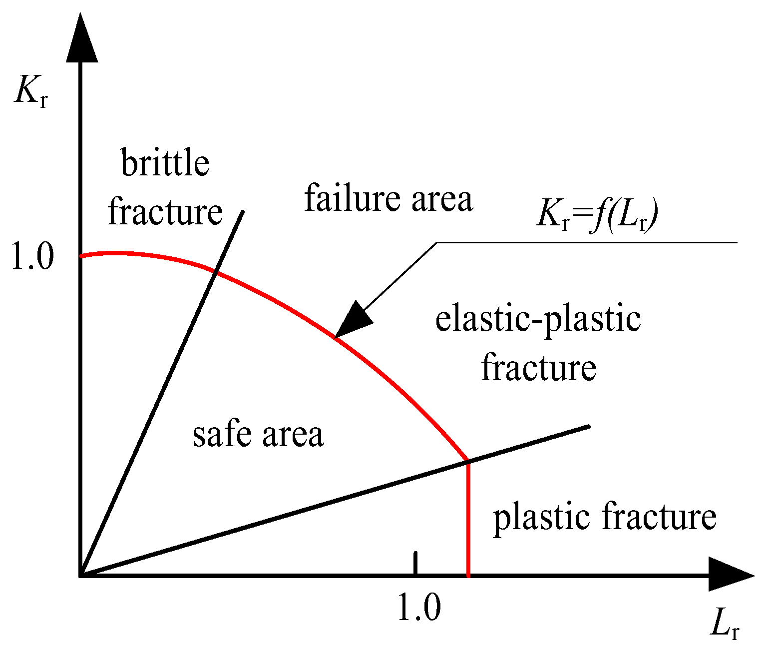
The R6 two-criterion procedure is a fitness-for-service method which is widely used to assess the structural integrity of flawed structures using the FAD. There are three failure regions in which FADs are dominated by brittle fracture, elastic–plastic deformation, and plastic collapse, respectively, as shown in
Figure 1. In the FAD, the safe area illustrates that all the points (
Kr,
Lr) are in the inner failure curves, which implies that the flawed structure is in good working condition.
Three options are provided in the R6 procedure, and the curve of option 3 in the FAD is characterized by the horizontal axis
Lr and vertical axis
Kr [
28]:
where
pmax is the limited load and
Je is the elastic
J integral.
In the authors’ previous work [
18], the equivalence principle of the stress intensity factor was developed to assess the cracked structures in the process of crack propagation. The horizontal axis
Lr of option 3 in the FAD was modified as follows:
The vertical axis
Kr of option 3 in the FAD was modified to consider the constraint effect near the crack tip, and it was expressed as follows:
3. The Finite Element Models
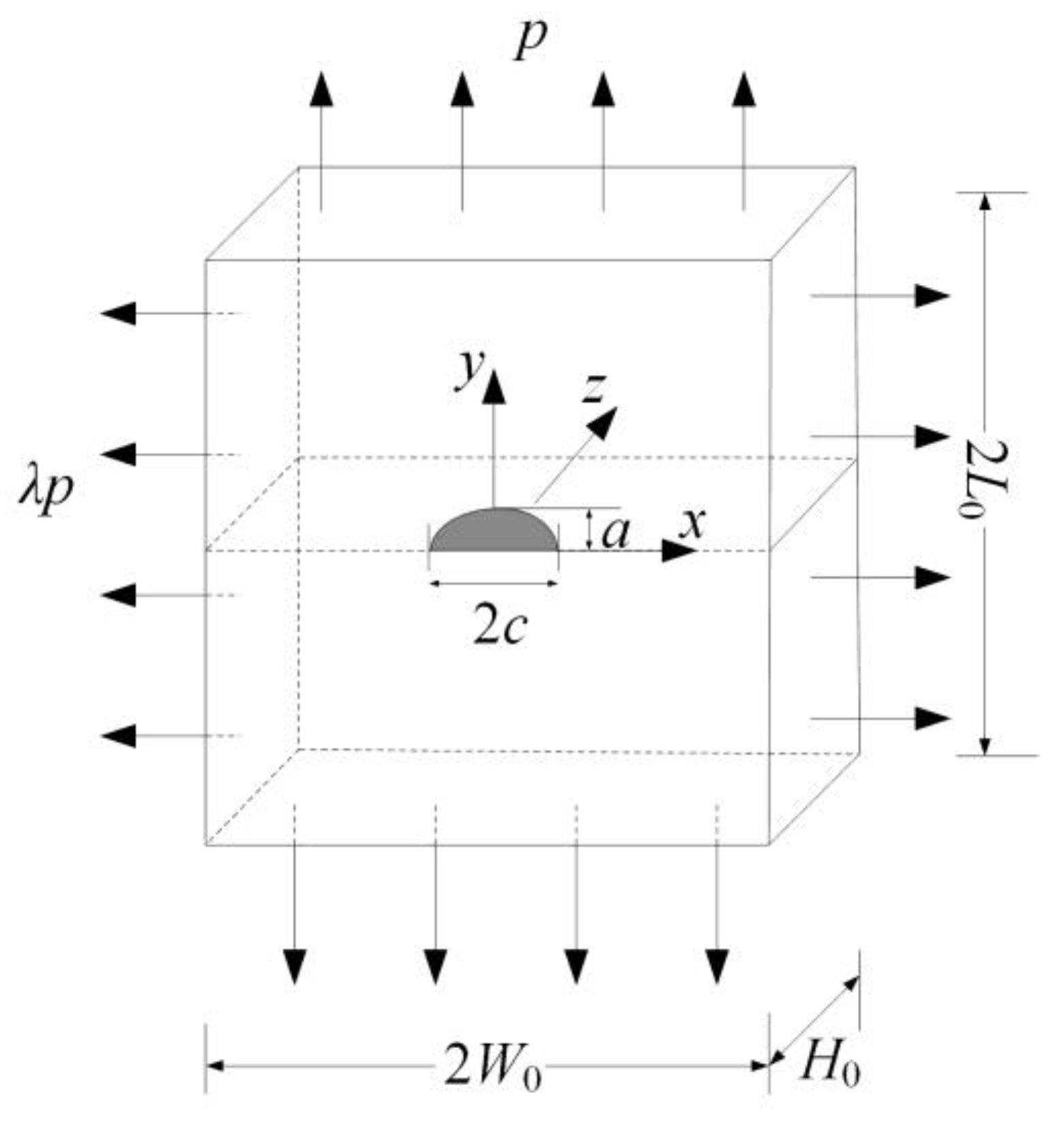
In this paper, three-dimensional finite element models with a semi-elliptical surface crack were established, and the crack propagation process of Q345 steel under small-scale creep conditions has been simulated using code ABAQUS 6.14. The creep strain of metallic materials can be generated once the environmental temperature reaches about 30% of their melting point. In practice, Q345 steel could serve in extreme working conditions where the temperature reaches 400 °C [
21,
29]. The studied temperature was chosen as 400 °C to satisfy the small-scale creep condition. The models were subjected to biaxial tensile loading, and the geometric configurations of the plate are shown in
Figure 2, where the width 2
W0 = 100 mm, the thickness
H0 = 50 mm, and the length 2
L0 = 100 mm.
It was assumed that the
J integral can describe crack tip fields in small-scale creep conditions and the mechanical behavior of Q345 steel at high temperatures can be expressed by the Ramberg–Osgood power law:
where
σs is the yield stress,
εs is the yield strain,
E is the Young’s modulus,
α is the material constant, and
n is the strain-hardening exponent.
On the basis of the test data of Q345 steel at 400 °C in the reference [
30], the material parameters of Q345 steel in the simulation can be obtained by the fitting method, namely,
α = 1.0 and
n = 7.2. According to the test data [
30], the elastic modulus
E = 174 GPa and the yield stress
σs = 283 MPa at 400 °C. Note that fracture mechanics theories were used in this paper, in which the microstructure factors were not considered.
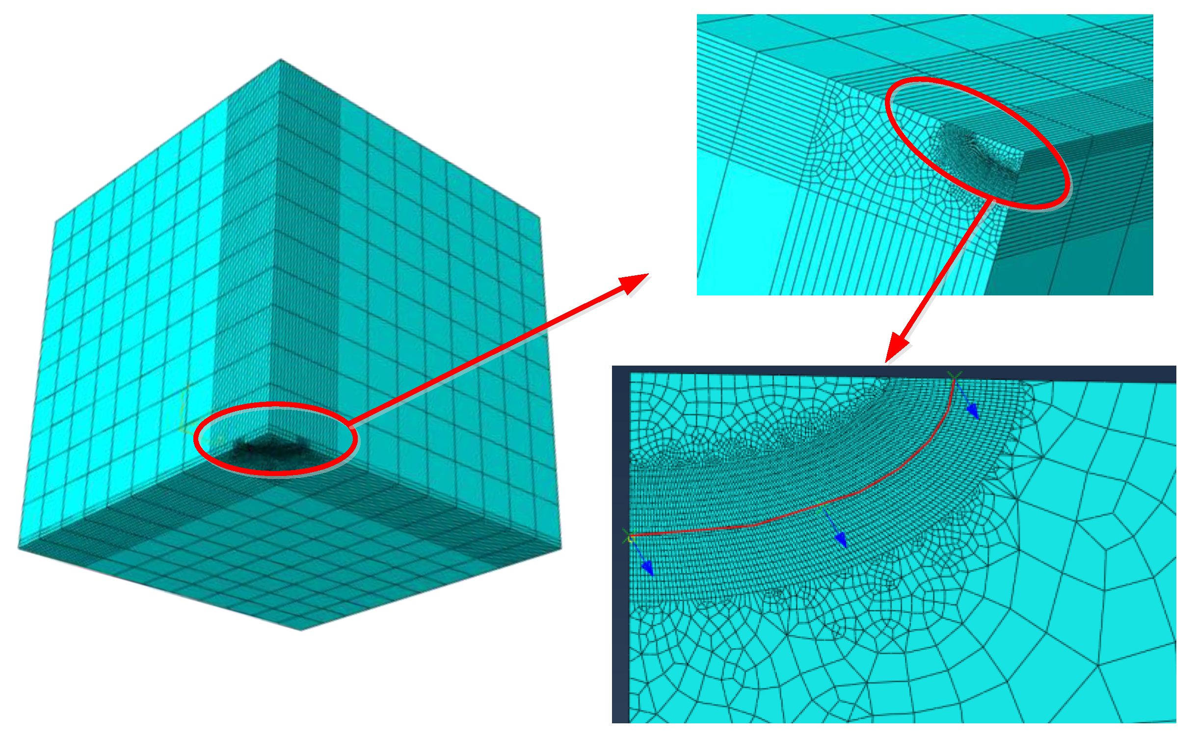
Based on the geometric symmetry of the structure, only one quarter of the plate was modeled. In the finite element simulation, symmetric conditions were applied to the sides of the model. Note that the 20-node hexahedron element (C3D20) was selected for the analysis to simulate the stress singularity. It was assumed that the initial crack length 2
c0 = 2 mm and the aspect ratio
a/
c of the crack remains constant in the process of crack propagation. To be concise, only the finite element model with an initial crack is displayed in
Figure 3. In the finite element model with an initial crack, the number of elements was 35,404, and the number of nodes was 147,751. The information of mesh size can be directly extracted from the finite element models using code ABAQUS. The
q vectors of code ABAQUS were used to define the crack propagation direction. In addition, 6 contours around the crack tip were used in the simulation, and the average value of the
J integral and
K was calculated by using the results extracted from the outer 5 contours.
The finite element software ABAQUS enables the direct extraction of the stress intensity factor solutions from the simulation results, namely finite element solutions. The stress intensity factor solutions can be calculated using Equation (1), namely theoretical solutions. In fact, Equation (1) for stress intensity factor K has been widely used in both engineering problems and theoretical research, and reliability can be guaranteed. In this study, the validity of the finite element models was verified by comparing the finite element solutions and theoretical solutions for the stress intensity factor. The solutions for the stress intensity factor at the deepest point (
θ = 90°) were listed in
Table 1; the relative difference between the two kinds of solutions was acceptable, which guaranteed the reliability of the finite element models. Therefore, finite element numerical results and the conclusion based on the numerical results were reliable.
4. The Numerical Results and Discussion
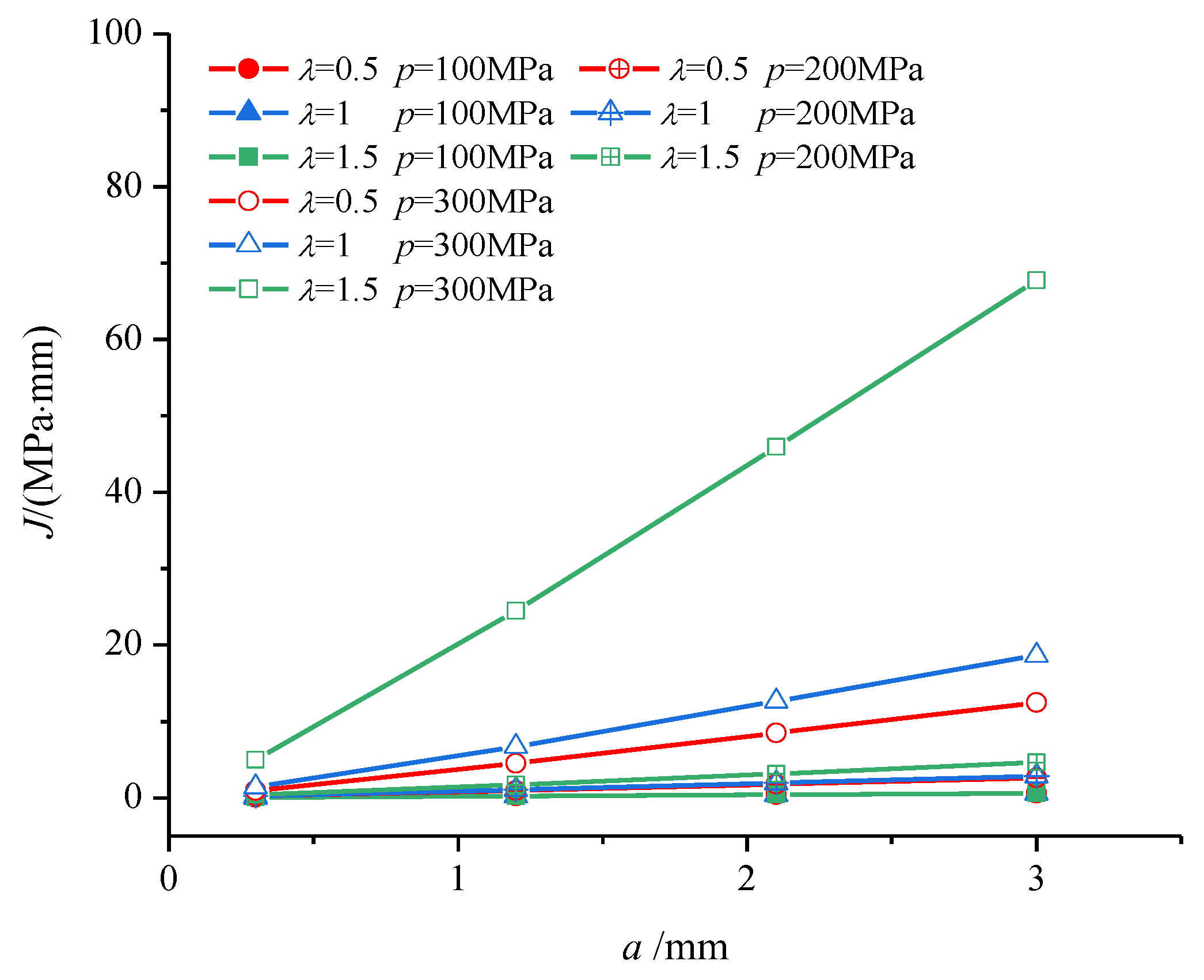
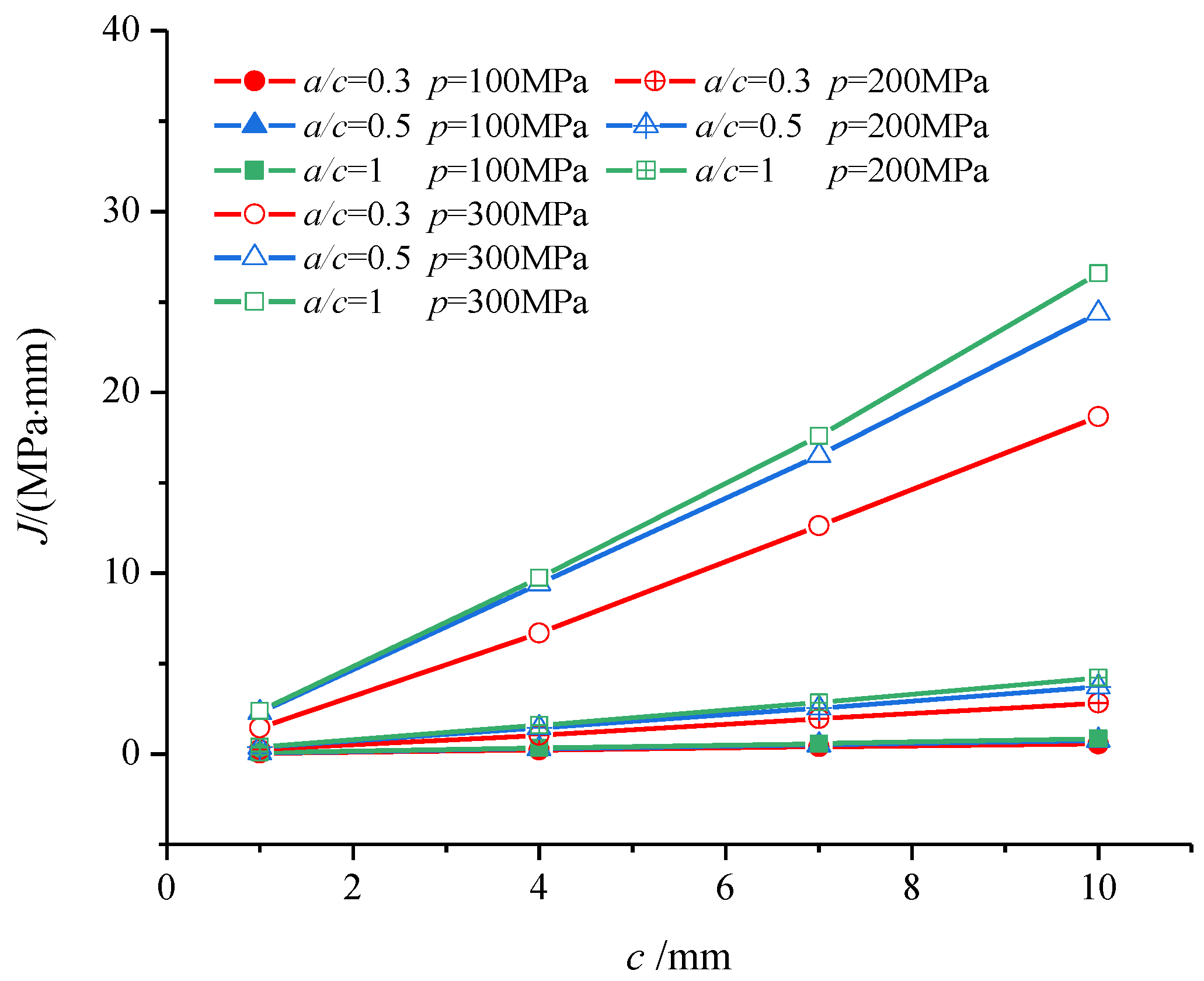
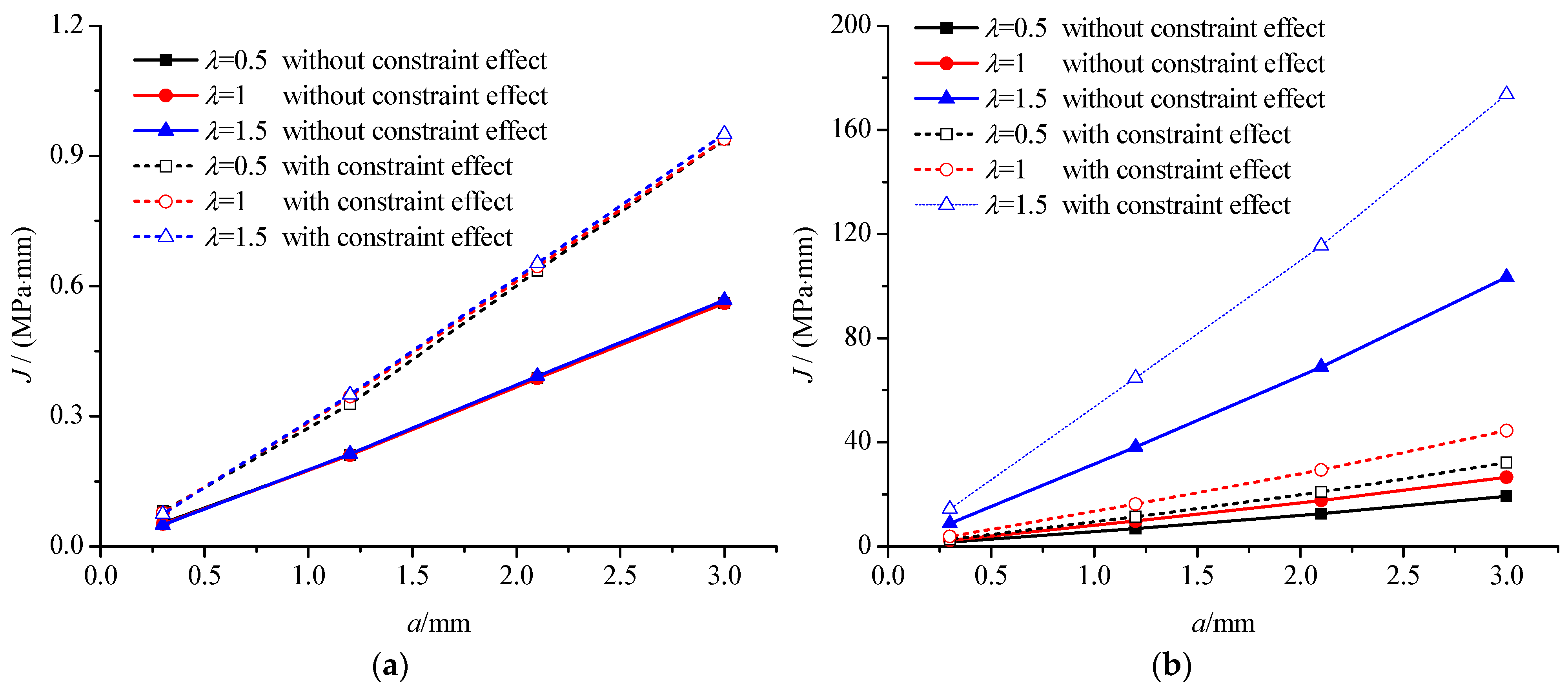
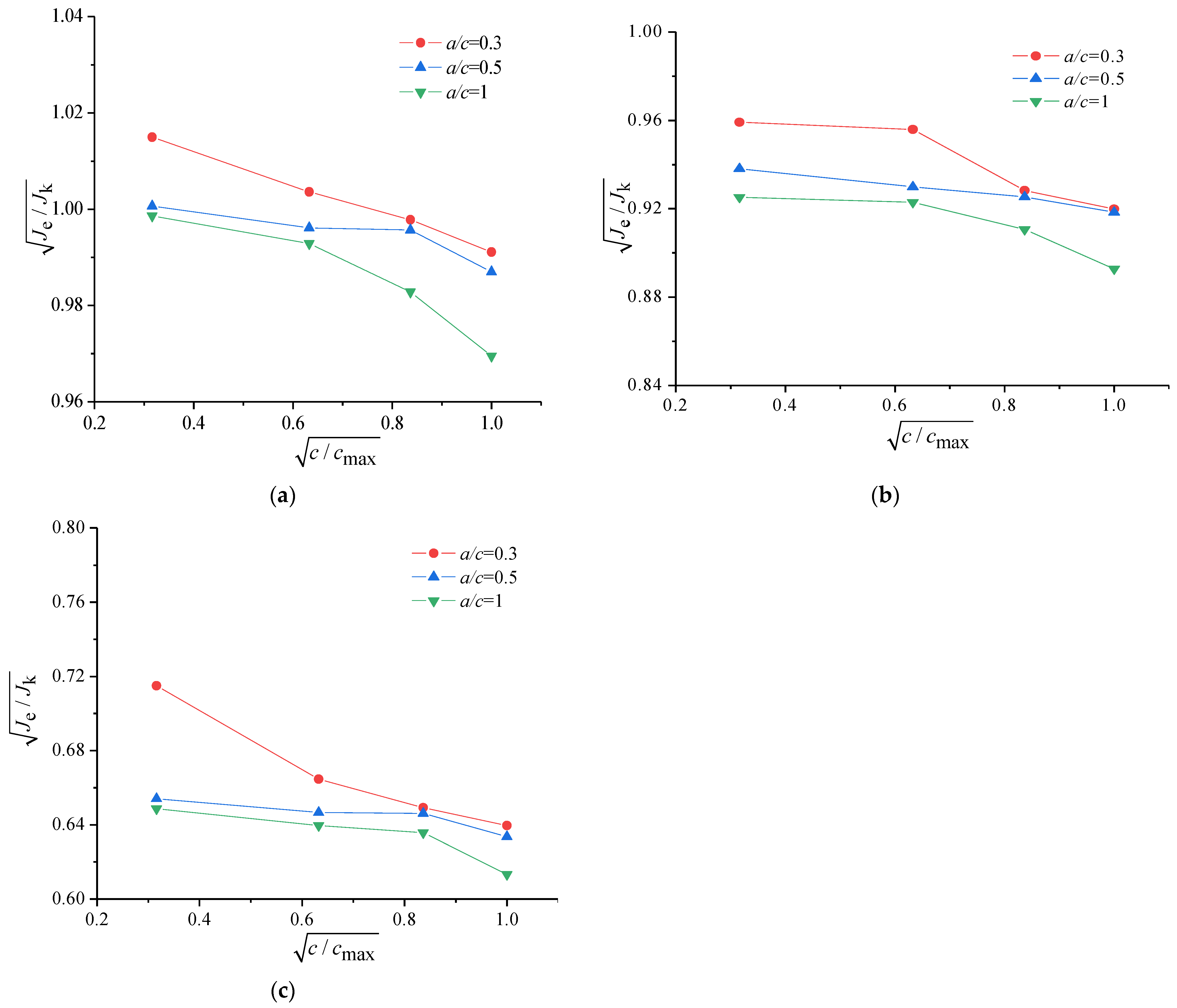
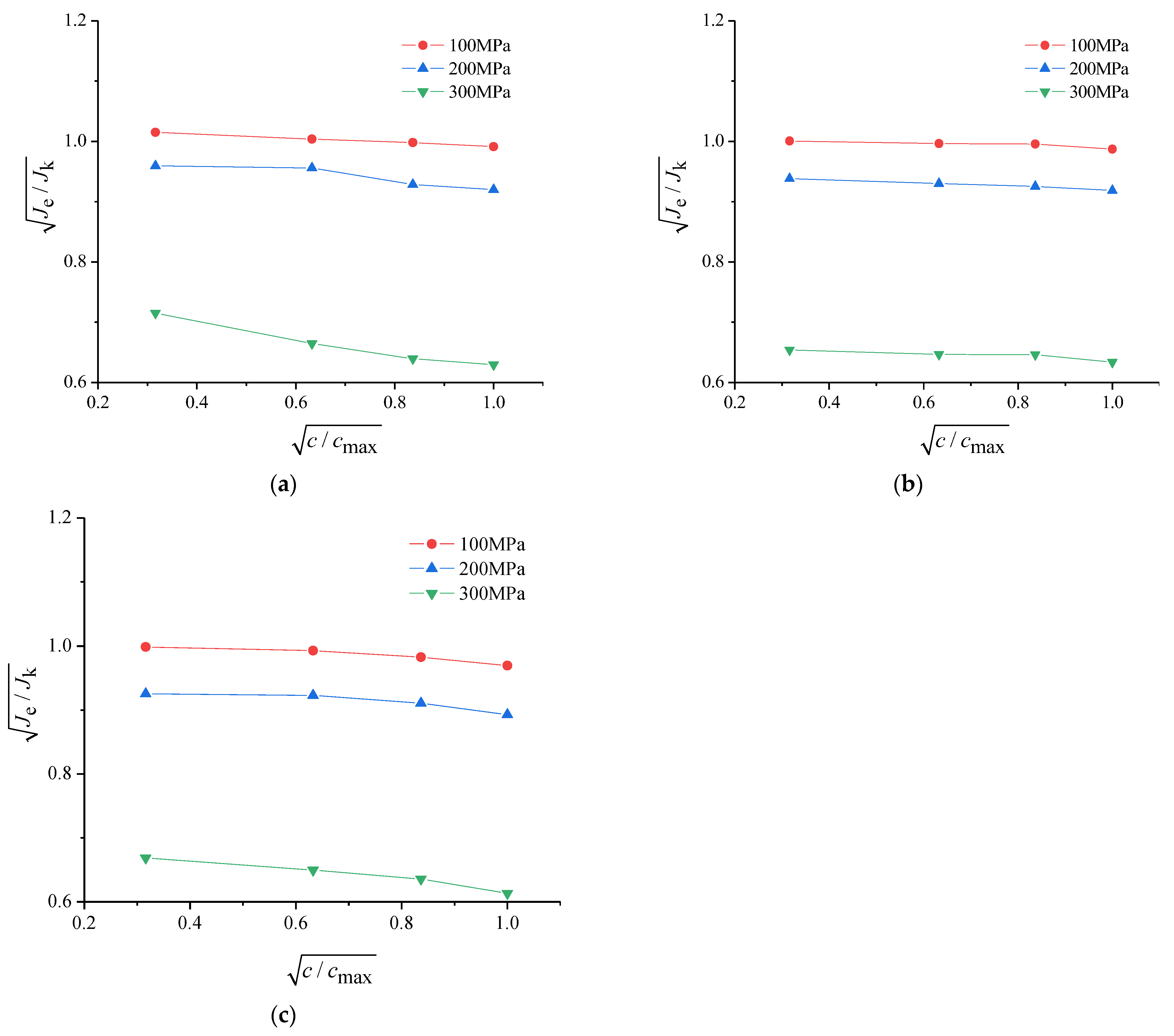
4.1. Analysis of J Integral in Creep Crack Propagation Process
In this section, the J integral was chosen to describe the crack tip fields of defective Q345 steel in small-scale creep conditions. The shape characters of the semi-elliptical surface crack were expressed by an aspect ratio
a/
c. Three groups of cracks with different aspect ratios have been investigated, in which the influence of the biaxial loading ratio
λ was studied. The J integral near the crack tip of defective Q345 steel was directly extracted from the finite element simulation results at 400 °C, and the results are shown as
Figure 4 and
Figure 5. Furthermore, the influence of the constraint effect near the crack tip on the J integral has been investigated, as shown in
Figure 6. The conclusions can be obtained from
Figure 4,
Figure 5 and
Figure 6:
(1) The influence of the biaxial loading ratio on the J integral was slight for relatively low stress levels, and it gradually became prominent with the improvement in the stress level.
(2) The value of the J integral increased with the increase in the crack length growth and the aspect ratio of the semi-elliptical surface crack, in which the relative increase could reach 52.2%.
(3) The constraint effect near the crack tip exhibited significant influence on the J integral, and the maximal relative increase was 67.9% in this study, which implies that the constraint effect should be considered in the structural assessment using the J-based procedure.
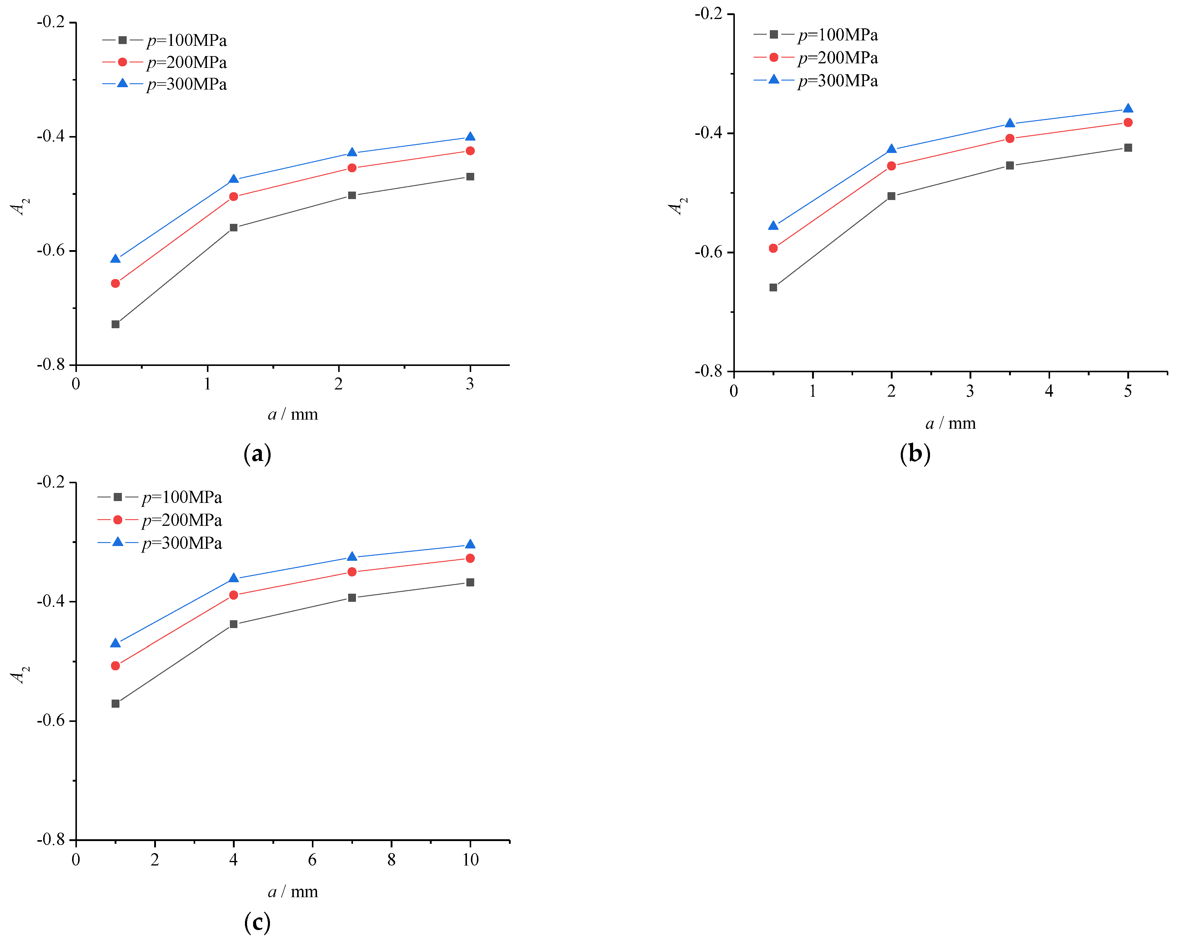
4.2. Analysis of Constraint Effect on Creep Crack Propagation Process
On the basis of the finite element simulation results and J-A
2 three-term solutions, an analysis on the constraint effect near the crack tip in the process of creep crack propagation has been performed using the J-A
2 two-parameter method, in which the influence of the crack aspect ratio, loading level, and biaxial loading ratio was studied. The A
2 was used to describe the constraint effect level near the crack tip, and the solution was taken at a normalized distance
r/(
J/
σs) = 2 from the crack tip. The numerical results are shown as
Figure 7,
Figure 8 and
Figure 9.
(1) A high constraint effect level occurred near the crack tip of Q345 steel in small-scale creep conditions, and the influence of the constraint effect on crack tip fields could be enhanced due to crack growth.
(2) The influence of the biaxial loading ratio on the constraint effect level was slight for relatively low stress, levels and it gradually became prominent with the increase in the stress level in small-scale creep conditions.
(3) The constraint effect level could be improved with the increase in the aspect ratio of the semi-elliptical surface crack and applied loading level.
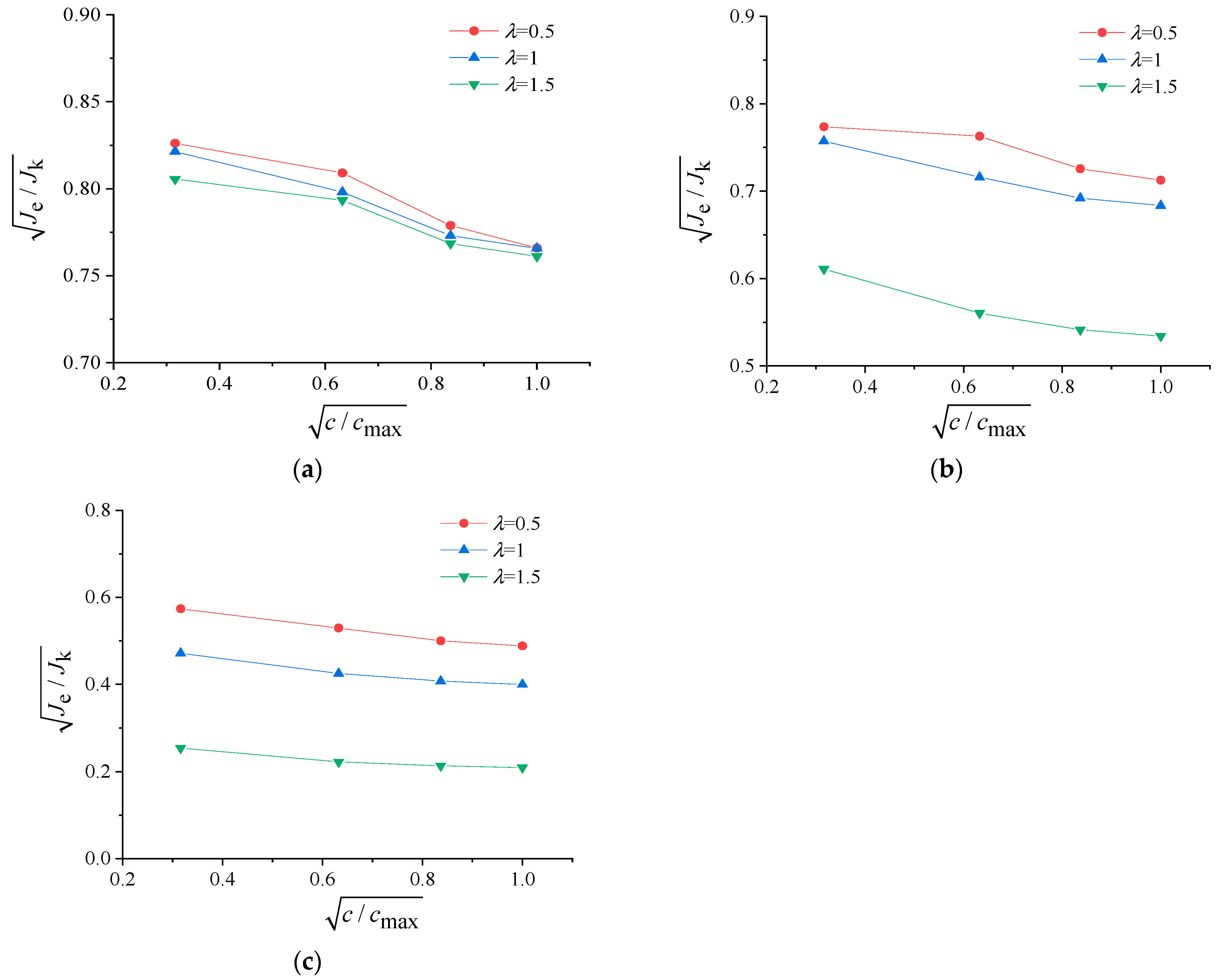
4.3. Structural Integrity Assessments for the Flawed Structure
In the previous paper [
18], a modified option 3 of R6 was developed in which the influence of the constraint effect and crack growth was considered, and the horizontal axis Lr and vertical axis Kr of option 3 in the FAD were expressed by Equation (7) and Equation (8), respectively. In this section, the modified option 3 of R6 was chosen to assess the structural integrity of the flawed structure made of Q345 steel in small-scale creep conditions. On the basis of the numerical results, the structural integrity assessments for the three-dimensional plates with a semi-elliptical surface crack were performed in which the influence of the biaxial loading ratio, the aspect ratio of the crack, and the loading level was studied, and the assessment results are shown as
Figure 10,
Figure 11 and
Figure 12, respectively.
(1) The safe area in the FAD decreased with the increased biaxial loading ratio, and the influence could be more prominent with the increase in the stress level.
(2) The decrease in the safe area in the FAD could occur due to an increase in the aspect ratio of the crack in the process of creep crack propagation, which could endanger the structural integrity of the structure.
(3) The increase in the loading level could lead to a decrease in the safe area in the FAD, in which the influence may be sharply enhanced due to high stress levels, and the maximal relative increase was 58.1% in this study.
5. Conclusions
This paper aimed to resolve the fracture problem of defective Q345 steel in small-scale creep conditions, and the creep crack propagation process was simulated at 400 °C. It is assumed that the J integral can describe crack tip fields in small-scale creep conditions. The constraint effect near the crack tip in the process of creep crack propagation was analyzed using the J-A2 two-parameter method, and the structural integrity of the cracked structure subjected to biaxial loading was assessed. The main works and conclusions were summarized as follows:
(1) The increase in the aspect ratio of the semi-elliptical crack and biaxial loading ratio could lead to an increase in the J integral in small-scale creep conditions, in which the relative increase could reach 52.2% in this study.
(2) A high constraint effect level could occur near the crack tip of defective Q345 steel and the constraint effect could be enhanced due to crack growth, leading to a significant increase in the J integral, and the maximal relative increase was 67.9% in this study, which demonstrates that the constraint effect should be considered in the structural integrity assessment for the structures made of Q345 steel.
(3) The constraint effect level near the crack tip could be distinctly affected by the aspect ratio of the semi-elliptical crack, applied loading level, and biaxial loading ratio. The influence of the biaxial loading ratio on the constraint effect level was slight for relatively low stress levels, and it gradually became prominent with the increase in the stress level.
(4) The structural integrity assessment curves were provided for the three-dimensional cracked structures made of Q345 steel in the process of creep crack propagation using the previously modified R6 procedure. The safe area in the FAD decreased with the increase in the biaxial loading ratio, loading level, and aspect ratio of the crack, and the maximal relative increase was 58.1% in this study.


