


Experimental Investigation of Vibration Control in Timber–Concrete Composite (TCC) Floors Using Tuned Mass Damper


Abstract
1. Introduction
1.1. Overview of Research in Timber Floor Vibration
1.2. Application of TMD to Floor Systems
1.3. Research on SMA–TMD
2. Development and Tests of the Pre-Strained SMA–TMD
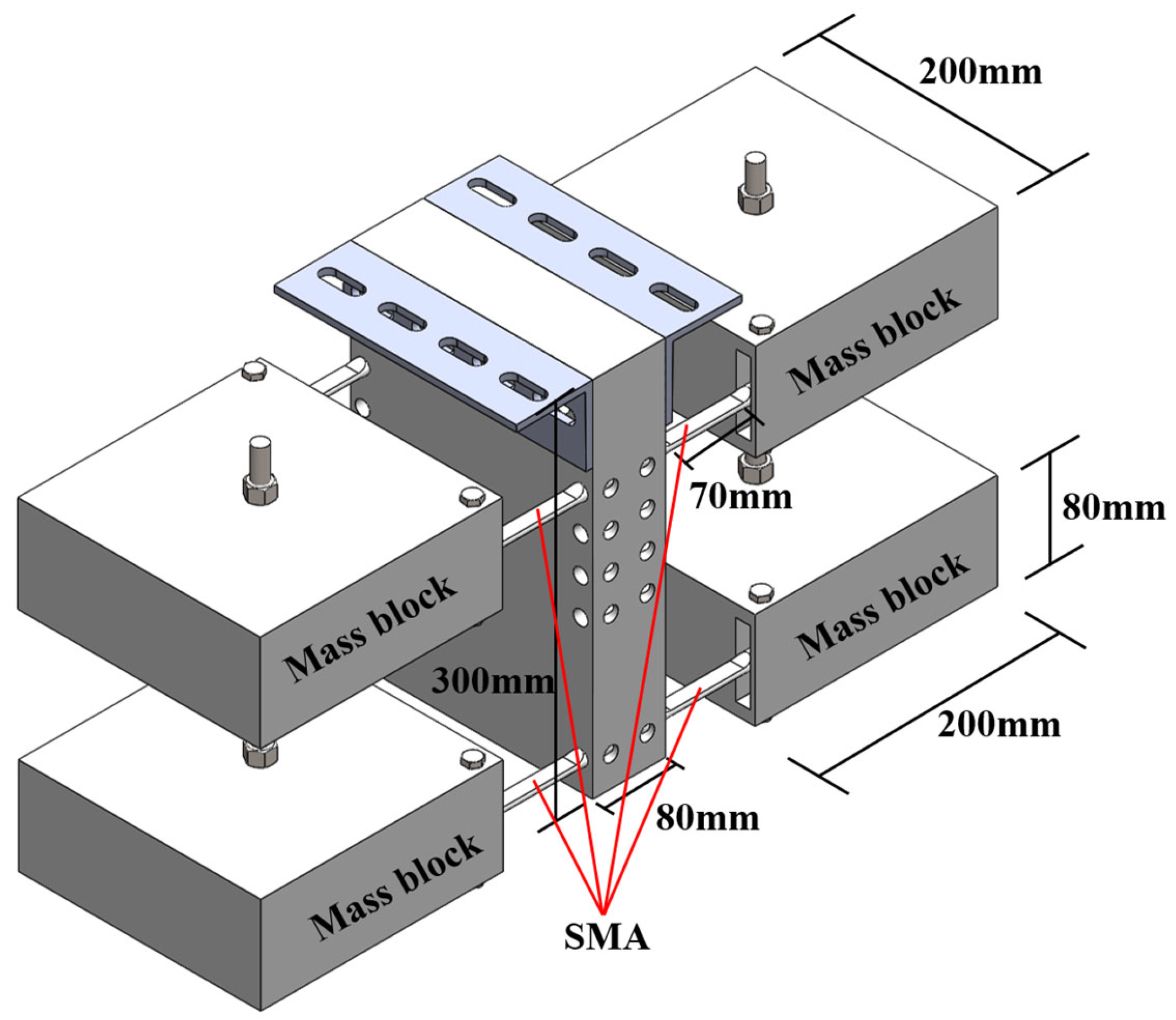
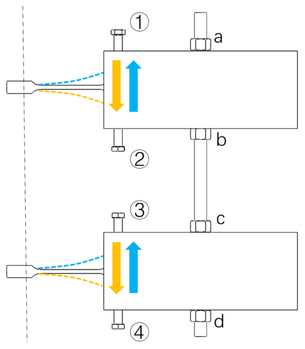
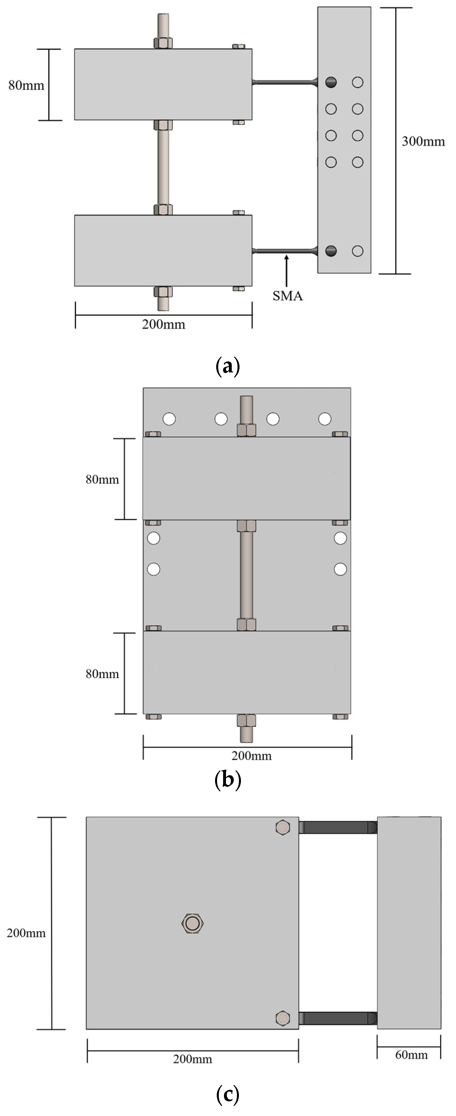
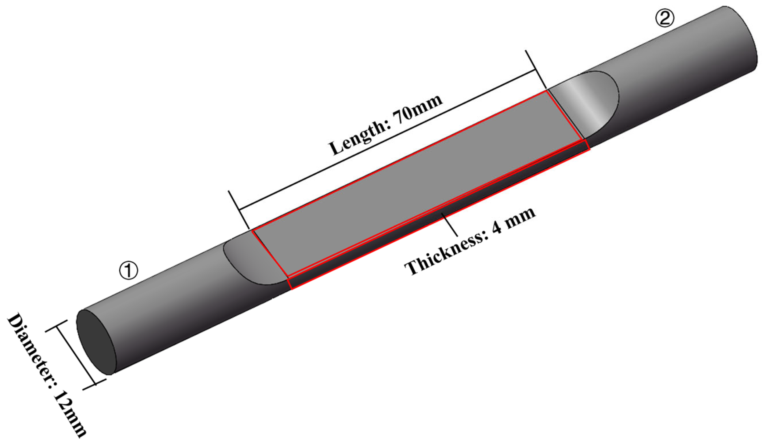
2.1. Pre-Strained SMA–TMD Design
2.2. Experimental Testing Methods for the SMA–TMD
2.3. Results and Analysis
3. Application of the SMA–TMD to the TCC Floor
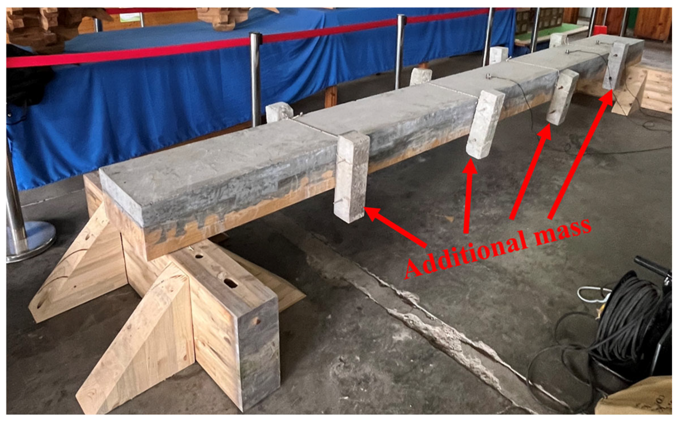
3.1. The Tested TCC Floor
3.2. Timber Floor Vibration Evaluation Standards
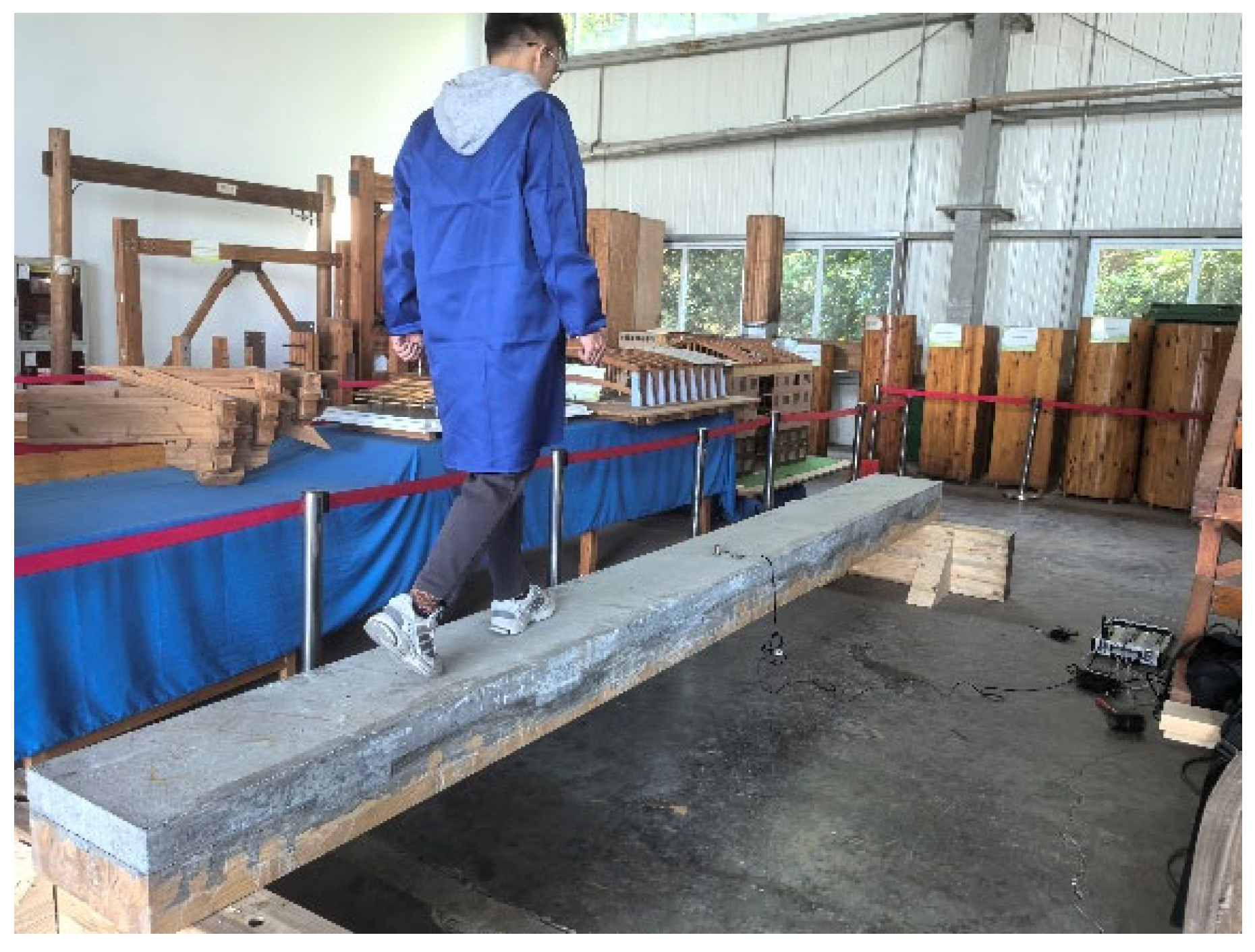
3.3. Testing the Effectiveness of the SMA–TMD on TCC Floor Vibration Reduction
3.4. Evaluating the Robustness of the SMA–TMD
4. Conclusions
- The damping ratio of the SMA–TMD increases with the increase in pre-strain level. Specifically, without any pre-strain, the damping ratio of the SMA–TMD is 0.8621%. As the pre-strain increases, the damping ratio continues to rise, reaching 1.6949% when the pre-strain is 2.92%. Additionally, as the pre-strain increases, the natural frequency slightly increases.
- The pre-strained SMA–TMD significantly reduces the vibration response of the TCC floor, with the highest reduction of peak acceleration by 49.91%, RF (Response Factor) by 40.82% and VDV (Vibration Dose Value) by 44.47%. Compared with the SMA–TMD system without pre-strain, there is an improvement in vibration reduction.
- The pre-strained SMA–TMD has stronger robustness and better adaptability to floor mass changes. Specifically, compared with non-pre-strained SMA–TMD, the pre-strained SMA–TMD showed more consistent performance, retaining its vibration control capability even after changes in the floor frequency.
Author Contributions
Funding
Data Availability Statement
Conflicts of Interest
References
- Nyabongo, E.; Li, X. Development of energy-early-dissipated braces based on web buckling of low-yield I-section steel. J. Constr. Steel Res. 2024, 217, 108672. [Google Scholar] [CrossRef]
- Qiu, Z.; Chen, R.; Gan, X.; Wu, C. Torsional damper design for diesel engine: Theory and application. Phys. Scr. 2024, 99, 125214. [Google Scholar] [CrossRef]
- He, D.; Xu, H.; Wang, M.; Wang, T. Transmission and Dissipation of Vibration in a Dynamic Vibration Absorber-Roller System Based on Particle Damping Technology. Chin. J. Mech. Eng. 2024, 37, 108. [Google Scholar] [CrossRef]
- Yang, J.; Liang, S.; Zhu, X.; Dang, L.; Shen, T.; Zhou, S. Experimental and theoretical research on a shear-bending-metallic-damper with a double-phased yield mechanism. J. Constr. Steel Res. 2023, 203, 107839. [Google Scholar] [CrossRef]
- Yuan, X.; Qiu, T.; Tian, T. Design and modelling methodology for a new magnetorheological damper featuring a multi-stage circumferential flow mode. Int. J. Mech. Mater. Des. 2022, 18, 785–806. [Google Scholar] [CrossRef]
- Khalfi, B.; Ross, A. Transient response of a plate with partial constrained viscoelastic layer damping. Int. J. Mech. Sci. 2013, 68, 304–312. [Google Scholar] [CrossRef]
- Jarnerö, K.; Brandt, A.; Olsson, A. In Situ Testing of Timber Floor Vibration Properties. In Proceedings of the 11th World Conference on Timber Engineering (WCTE 2010), Trentino, Italy, 20–24 June 2010. [Google Scholar]
- British Standards Institution. UK National Annex to Eurocode 5: Design of Timber Structures In Part 1-1: General, Common Rules and Rules for Buildings London; British Standards Institution: London, UK, 2004. [Google Scholar]
- Hu, L.; Chui, Y. Development of a Design Method to Control Vibrations Induced by Normal Walking Action in Wood-Based Floors. In Proceedings of the 8th World Conference on Timber Engineering, Oslo, Norway, 19–22 June 2023. [Google Scholar]
- Ebadi, M.M.; Doudak, G.; Smith, I. Evaluation of floor vibration caused by human walking in a large glulam beam and deck floor. Eng. Struct. 2019, 196, 109349. [Google Scholar] [CrossRef]
- Saidi, I.; Haritos, N.; Gad, E.F.; Wilson, J.L. Floor vibrations due to human excitation—Damping perspective. In Earthquake Engineering in Australia; Australian Earthquake Engineering Society: Canberra, Australia, 2006. [Google Scholar]
- Racic, V.; Pavic, A.; Brownjohn, J.M.W. Experimental identification and analytical modelling of human walking forces: Literature review. J. Sound Vib. 2009, 326, 1–49. [Google Scholar] [CrossRef]
- Pavic, A.; Reynolds, P. Vibration serviceability of long-span concrete building floors. Part 1: Review of background information. Shock Vib. Dig. 2002, 34, 191–211. [Google Scholar]
- Bernard, E.S. Dynamic Serviceability in Lightweight Engineered Timber Floors. J. Struct. Eng. 2008, 134, 258–268. [Google Scholar] [CrossRef]
- Weckendorf, J.; Ussher, E.; Smith, I. Dynamic response of CLT plate systems in the context of timber and hybrid construction. Compos. Struct. 2016, 157, 412–423. [Google Scholar] [CrossRef]
- Shi, B.; Liu, W.; Yang, H. Experimental investigation on the long-term behaviour of prefabricated timber-concrete composite beams with steel plate connections. Constr. Build. Mater. 2021, 266, 120892. [Google Scholar] [CrossRef] [PubMed]
- Ljunggren, F. In Floor Vibration—Dynamic Properties and Subjective Perception. Ph.D. Thesis, Luleå University of Technology, Luleå, Sweden, 2006. [Google Scholar]
- Ljunggren, F.; Ågren, A. Dynamic and Subjective Analysis of a Lightweight/Semi-Heavyweight Floor in a Laboratory. Build. Acoust. 2006, 13, 255–272. [Google Scholar] [CrossRef]
- Jarnerö, K.; Brandt, A.; Olsson, A. Vibration properties of a timber floor assessed in laboratory and during construction. Eng. Struct. 2015, 82, 44–54. [Google Scholar] [CrossRef]
- Rijal, R.; Samali, B.; Shrestha, R.; Crews, K. Experimental and analytical study on dynamic performance of timber-concrete composite beams. Constr. Build. Mater. 2015, 75, 46–53. [Google Scholar] [CrossRef]
- Yeoh, D.; Fragiacomo, M.; De Franceschi, M.; Heng Boon, K. State of the art on timber-concrete composite structures: Literature review. J. Struct. Eng. 2011, 137, 1085–1095. [Google Scholar] [CrossRef]
- Klotz, S.; Holschemacher, K.; Köhler, S. Wirtschaftlichkeit von Holz-Beton-Verbunddecken. In Proceedings of the Innovationen im Bauwesen-Holz-Beton-Verbund, Leipzig, Germany, 18–19 March 2004; pp. 269–279. [Google Scholar]
- Newcombe, M.P.; Van Beerschoten, W.A.; Carradine, D.; Pampanin, S.; Buchanan, A.H. In-plane experimental testing of timber-concrete composite floor diaphragms. J. Struct. Eng. 2010, 136, 1461–1468. [Google Scholar] [CrossRef]
- Smith, I.; Frangi, A. Use of Timber in Tall Multi-Storey Buildings; International Association for Bridge and Structural Engineering: Zurich, Switzerland, 2014. [Google Scholar]
- Movaffaghi, H.; Pyykkö, J.; Yitmen, I. Value-driven design approach for optimal long-span timber-concrete composite floor in multi-storey wooden residential buildings. Civ. Eng. Environ. Syst. 2020, 37, 100–116. [Google Scholar] [CrossRef]
- Stepinac, M.; Šušteršič, I.; Gavrić, I.; Rajčić, V. Seismic design of timber buildings: Highlighted challenges and future trends. Appl. Sci. 2020, 10, 1380. [Google Scholar] [CrossRef]
- Sebastian, W.; Webb, S.; Nagree, H.S. Orthogonal distribution and dynamic amplification characteristics of partially prefabricated timber-concrete composites. Eng. Struct. 2020, 219, 110693. [Google Scholar] [CrossRef]
- Zhang, X.; Hu, X.; Gong, H.; Zhang, J.; Lv, Z.; Hong, W. Experimental study on the impact sound insulation of cross laminated timber and timber-concrete composite floors. Appl. Acoust. 2020, 161, 107173. [Google Scholar] [CrossRef]
- Ghafar, N.H.A. In Vibration Performance of LVL-Concrete Composite Floor Systems. In Proceedings of the World Conference on Timber Engineering (WCTE 2008), Miyazaki, Japan, 2–5 June 2008. [Google Scholar]
- AbdGhafar, H.; Deam, B.L.; Fragiacomo, M. Dynamic Measurements of LVL-Concrete Composite Floors. In Proceedings of the 13th Asia Pacific Vibration Conference, University of Canterbury, Christchurch, New Zealand, 22–25 November 2009; pp. 1–8. [Google Scholar]
- Fragiacomo, M.; Lukaszewska, E. Development of prefabricated timber–concrete composite floor systems. Proc. Inst. Civ. Eng.-Struct. Build. 2011, 164, 117–129. [Google Scholar] [CrossRef]
- Shi, B.; Zhou, X.; Tao, H.; Yang, H.; Wen, B. Long-Term Behavior of Timber–Concrete Composite Structures: A Literature Review on Experimental and Numerical Investigations. Buildings 2024, 14, 1770. [Google Scholar] [CrossRef]
- Dolan, J.; Murray, T.; Johnson, J.; Runte, D.; Shue, B. Preventing annoying wood floor vibrations. J. Struct. Eng. 1999, 125, 19–24. [Google Scholar] [CrossRef]
- Talja, A.; Toratti, T. Effect on Floating Floors on the Vibration Performance of Wood-Concrete Composite Floors. In Proceedings of the World Conference on Timber Engineering (WCTE 2000), Whistler, BC, Canada, 31 July–3 August 2000. [Google Scholar]
- Mertens, C.; Martin, Y.; Dobbels, F. Investigation of the vibration behaviour of timber-concrete composite floors as part of a performance evaluation for the Belgian building industry. Build. Acoust. 2007, 14, 25–36. [Google Scholar] [CrossRef]
- Casagrande, D.; Giongo, I.; Pederzolli, F.; Franciosi, A.; Piazza, M. Analytical, numerical and experimental assessment of vibration performance in timber floors. Eng. Struct. 2018, 168, 748–758. [Google Scholar] [CrossRef]
- Hamm, P.; Richter, A.; Winter, S. Floor Vibrations–New Results. In Proceedings of the 11th World Conference on Timber Engineerig (WCTE2010), Riva del Garda, Trentino, Italy, 20–24 June 2010. [Google Scholar]
- Rijal, R.; Samali, B.; Crews, K.; Shrestha, R. Dynamic Behaviour of Timber-Concrete Composite Flooring Systems. In Proceedings of the 11th World Conference on Timber Engineering 2010, WCTE 2010, Trentino, Italy, 20–24 June; pp. 1815–1820.
- Skinner, J.; Harris, R.; Paine, K.; Walker, P.; Bregula, J. The characterisation of Connectors for the Upgrade of Timber Floors With Thin Structural Toppings. In Proceedings of the World Conference of Timber Engineering 2012, Auckland, New Zealand, 15–19 July 2012. [Google Scholar]
- Omenzetter, P.; Kohli, V.; Desgeorges, Y. Evaluation of timber-concrete floor performance under occupant-induced vibrations using continuous monitoring. Key Eng. Mater. 2013, 569, 230–237. [Google Scholar] [CrossRef]
- Fong, L.Y.; Ghafar, N.H.A.; Abd Rahman, N.; Fragiacomo, M.; Ibrahim, Z.; Buchanan, A. Comparison Between The Vibration Performance Of Lvlconcrete Composite (Lcc) Flooring System Made Of Malaysian And New Zealand Lvl. Malays. J. Civ. Eng. 2015, 27. [Google Scholar] [CrossRef]
- Marshall, E.J.; Granello, G.; Palermo, A. Vibration performance of timber-concrete composite floors: A case study. SESOC J. 2020, 33, 33–46. [Google Scholar]
- Mushina, J.; Abd Ghafar, N.; Yeoh, D.; Mushina, W.; Boon, K.H. Vibration Behaviour of Natural Timber and Timber Concrete Composite Deck System. In IOP Conference Series: Materials Science and Engineering; IOP Publishing: Bristol, UK, 2020; p. 012023. [Google Scholar]
- Hermann, F. Device For Damping Vibrations of Bodies. US Patent 89958, 18 April 1911. [Google Scholar]
- Xu, K.; Igusa, T. Dynamic characteristics of multiple substructures with closely spaced frequencies. Earthq. Eng. Struct. Dyn. 1992, 21, 1059–1070. [Google Scholar] [CrossRef]
- Yamaguchi, H.; Harnpornchai, N. Fundamental characteristics of Multiple Tuned Mass Dampers for suppressing harmonically forced oscillations. Earthq. Eng. Struct. Dyn. 1993, 22, 51–62. [Google Scholar] [CrossRef]
- Gu, M.; Chen, S.R.; Chang, C.C. Parametric study on multiple tuned mass dampers for buffeting control of Yangpu Bridge. J. Wind Eng. Ind. Aerodyn. 2001, 89, 987–1000. [Google Scholar] [CrossRef]
- Lin, C.C.; Wang, J.F.; Chen, B.L. Train-Induced Vibration Control of High-Speed Railway Bridges Equipped with Multiple Tuned Mass Dampers. J. Bridge Eng. 2005, 10, 398–414. [Google Scholar] [CrossRef]
- Chen, S.R.; Wu, J. Performance enhancement of bridge infrastructure systems: Long-span bridge, moving trucks and wind with tuned mass dampers. Eng. Struct. 2008, 30, 3316–3324. [Google Scholar] [CrossRef]
- Rainer, J.H.; Swallow, J.C. Dynamic behaviour of a gymnasium floor. Can. J. Civ. Eng. 1986, 13, 270–277. [Google Scholar] [CrossRef]
- Webster, A.; Vaicaitis, R. Application of Tuned Mass Dampers To Control Vibrations of Composite Floor Systems. Eng. J. 1992, 29, 116–124. [Google Scholar] [CrossRef]
- Setareh, M.; Hanson, R.D. Tuned Mass Dampers for Balcony Vibration Control. J. Struct. Eng. 1992, 118, 723–740. [Google Scholar] [CrossRef]
- Chen, Z.; Feng, Z.; Chen, J.; Sun, X.; Hua, X. Hybrid control of the vortex-induced vibration of a pedestrian landscape bridge based on aerodynamic measures and pulley-type TMD. J. Vib. Shock 2024, 43, 140–148. [Google Scholar]
- Huang, H.; Chang, W.-S. Application of pre-stressed SMA-based tuned mass damper to a timber floor system. Eng. Struct. 2018, 167, 143–150. [Google Scholar] [CrossRef]
- Huang, H.; Gao, Y.; Chang, W.-S. Human-induced vibration of cross-laminated timber (CLT) floor under different boundary conditions. Eng. Struct. 2020, 204, 110016. [Google Scholar] [CrossRef]
- Jiang, Z.-Q.; Liu, L.-T.; Chang, W.-S.; Wang, W.; Wang, Y.-H.; Huang, H. Enhancing CLT floor vibration mitigation with pre-strained shape memory alloy-tuned mass dampers. Structures 2024, 67, 106980. [Google Scholar] [CrossRef]
- Huang, H.; Mosalam, K.M.; Chang, W.-S. Adaptive tuned mass damper with shape memory alloy for seismic application. Eng. Struct. 2020, 223, 111171. [Google Scholar] [CrossRef]
- Huang, H.; Zhu, Y.-Z.; Chang, W.-S. Comparison of bending fatigue of NiTi and CuAlMn shape memory alloy bars. Adv. Mater. Sci. Eng. 2020, 2020, 8024803. [Google Scholar] [CrossRef]
- Huang, H.; Wang, C.; Chang, W.-S. Reducing human-induced vibration of cross-laminated timber floor—Application of multi-tuned mass damper system. Struct. Control Health Monit. 2021, 28, e2656. [Google Scholar] [CrossRef]
- Zieliński, T.; Duda, K. Frequency and Damping Estimation Methods—An Overview. Metrol. Meas. Syst. 2011, 18, 505–528. [Google Scholar] [CrossRef]
- BS EN 16929:2018; Test Methods—Timber Floors—Determination of Vibration Properties. British Standards Institution: Brussels, Belgium, 2018.
- Clough, R.W.; Penzien, J.; Griffin, D.S. Dynamics of Structures, 3rd ed.; McGraw-Hill: New York, NY, USA, 1993. [Google Scholar]
- BS 6472-1:2008; Guide to Evaluation of Human Exposure to Vibration in Buildings. In Part 1: Vibration Sources Other Than Blasting. British Standards Institution: London, UK, 2008.
- ISO 10137:2007; Bases for Design of Structures—Serviceability of Buildings and Walkways Against Vibrations. International Organization for Standardization (ISO): Geneva, Switzerland, 2007.
- Hartog, D. Mechanical Vibrations. In The Aeronautical Journal; McGraw-Hill: New York, NY, USA, 1957; Volume 61, p. 139. [Google Scholar]
- Huang, H.; Chang, W.-S.; Mosalam, K.M. Feasibility of shape memory alloy in a tuneable mass damper to reduce excessive in-service vibration. Struct. Control Health Monit. 2017, 24, e1858. [Google Scholar] [CrossRef]


| Test No. | Pre-Strain Level | Natural Frequency (Hz) | Damping Ratio |
|---|---|---|---|
| P1 | 0.00% | 9.96 | 0.8621% |
| P2 | 0.32% | 10.10 | 0.9901% |
| P3 | 1.33% | 10.06 | 1.2346% |
| P4 | 1.67% | 10.37 | 1.3889% |
| P5 | 1.95% | 11.04 | 1.6393% |
| P6 | 2.56% | 11.29 | 1.6760% |
| P7 | 2.92% | 12.43 | 1.6949% |
| Test No. | Floor Mass (kg) | Test Method | Natural Frequency (Hz) | Damping Ratio |
|---|---|---|---|---|
| C1 | 660 | Hammering method | 16.33 | 2.4133% |
| C2 | 660 + 80 | Hammering method | 15.78 | 1.7726% |
| C3 | 660 + 140 | Hammering method | 15.00 | 1.4845% |
| C4 | 660 + 260 | Hammering method | 13.78 | 1.6112% |
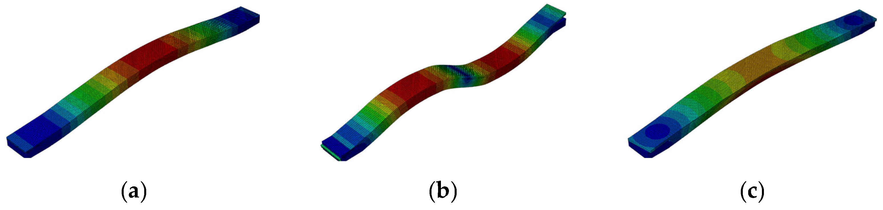
| f1 (Hz) | f2 (Hz) | f3 (Hz) |
|---|---|---|
| 16.69 | 35.02 | 45.50 |
| Place | Multiplying Factor (limit) for Exposure to Continuous Vibration |
|---|---|
| Office | 8 |
| Shopping mall | 4 |
| Dealing floor | 4 |
| Place and Time | Low Probability of Adverse Comment (m/s1.75) | Adverse Comment Possible (m/s1.75) | Adverse Comment Probable (m/s1.75) |
|---|---|---|---|
| Residential buildings 16 h day | 0.2–0.4 | 0.4–0.8 | 0.8–1.6 |
| Residential buildings 8 h night | 0.1–0.2 | 0.2–0.4 | 0.4–0.8 |
| Test No. | SMA–TMD | Pre-Strain Level of the SMA–TMD | Additional Mass (kg) |
|---|---|---|---|
| S1 | - | 260 | |
| S2 | √ | 0 | 0 |
| S3 | √ | 0 | 80 |
| S4 | √ | 0 | 140 |
| S5 | √ | 0 | 260 |
| S6 | √ | 2.92% | 0 |
| S7 | √ | 2.92% | 80 |
| S8 | √ | 2.92% | 140 |
| S9 | √ | 2.92% | 260 |
| F1 | - | 260 | |
| F2 | √ | 0 | 0 |
| F3 | √ | 0 | 80 |
| F4 | √ | 0 | 140 |
| F5 | √ | 0 | 260 |
| F6 | √ | 2.92% | 0 |
| F7 | √ | 2.92% | 80 |
| F8 | √ | 2.92% | 140 |
| F9 | √ | 2.92% | 260 |
| Test No. S1 | Test No. S5 | Test No. S9 | |
|---|---|---|---|
| Floor mass (kg) | 660 + 260 | 660 + 260 | 660 + 260 |
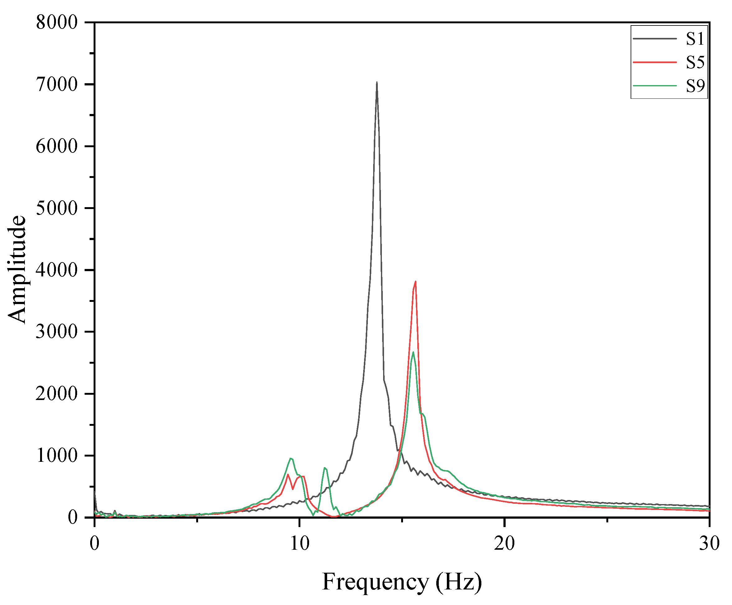
| Natural frequency of the floor (Hz) | 13.78 | 13.78 | 13.78 |
| Pre-strain level (%) | - | 0 | 2.92% |
| TMD mass (kg) | - | 24.9 | 24.9 |
| TMD natural frequency (Hz) | - | 9.96 | 12.43 |
| TMD damping ratio (%) | - | 0.8621 | 1.6949 |
| Mass ratio (%) | - | 3.7 | 3.7 |
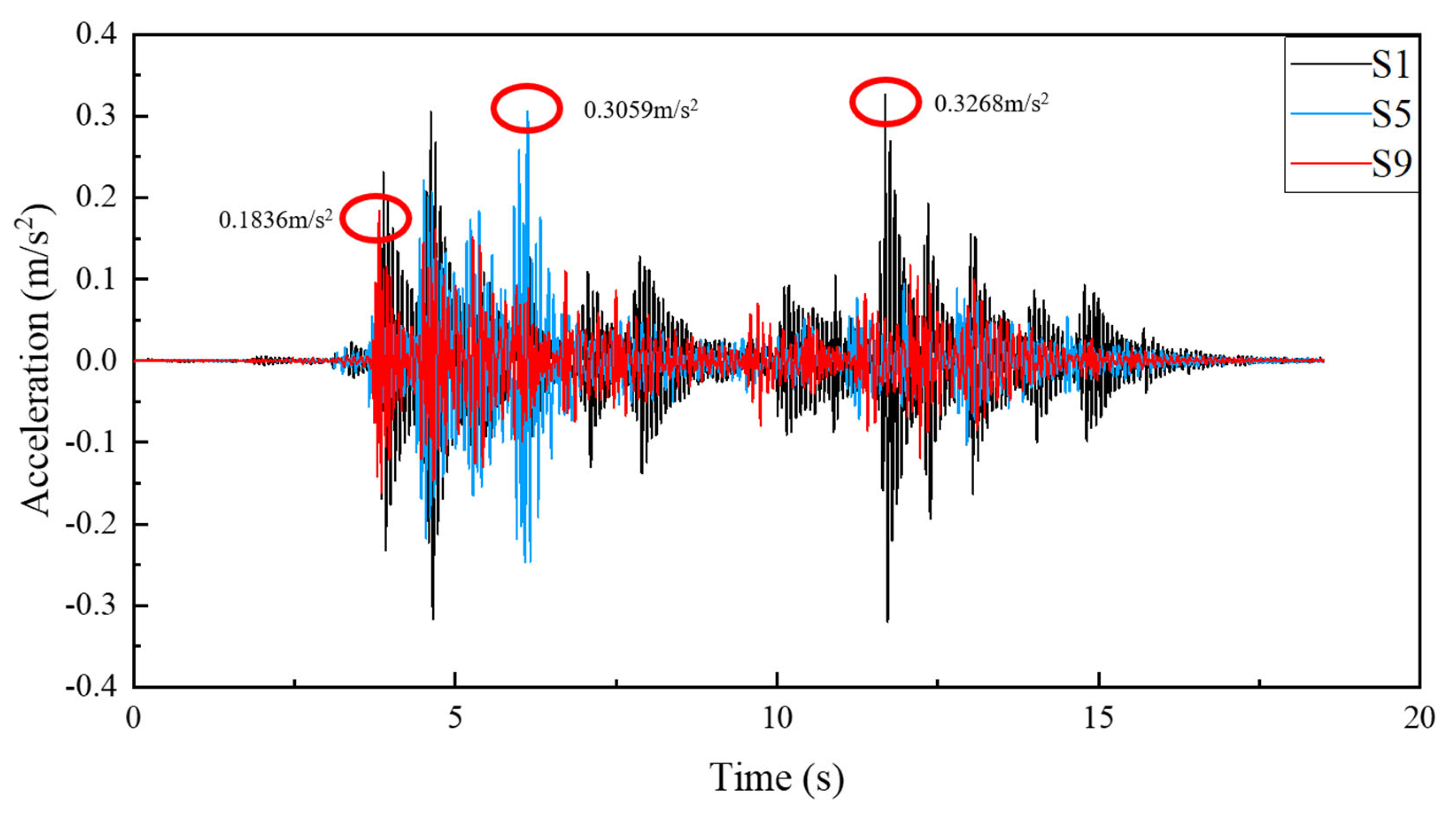
| 0.3268 | 0.3059 | 0.1836 | |
| Peak acceleration reduction | - | 6.40% | 43.82% |
| RF | 8.4159 | 6.4877 | 4.9804 |
| RF reduction | - | 22.91% | 40.82% |
| 0.1617 | 0.1368 | 0.0898 | |
| VDV reduction | - | 15.40% | 44.47% |
| Test No. F1 | Test No. F5 | Test No. F9 | |
|---|---|---|---|
| Floor mass (kg) | 660 + 260 | 660 + 260 | 660 + 260 |
| Natural frequency of the floor (Hz) | 13.78 | 13.78 | 13.78 |
| Pre-strain level (%) | - | 0 | 2.92% |
| TMD mass (kg) | - | 24.9 | 24.9 |
| TMD natural frequency (Hz) | - | 9.96 | 12.43 |
| TMD damping ratio (%) | - | 0.8621 | 1.6949 |
| Mass ratio (%) | - | 3.7 | 3.7 |
| 0.4390 | 0.3740 | 0.2991 | |
| Peak acceleration reduction | - | 14.81% | 31.87% |
| RF | 12.6429 | 10.6855 | 11.7325 |
| RF reduction | - | 15.48% | 7.20% |
| 0.2289 | 0.1808 | 0.1846 | |
| VDV reduction | - | 21.01% | 19.35% |
| Test No. S1 | Test No. S2 | Test No. S3 | Test No. S4 | Test No. S5 | Test No. S6 | Test No. S7 | Test No. S8 | Test No. S9 | |
|---|---|---|---|---|---|---|---|---|---|
| Floor | TCC | TCC | TCC | TCC | TCC | TCC | TCC | TCC | TCC |
| Floor mass (kg) | 660 + 260 | 660 | 660 + 80 | 660 + 140 | 660 + 260 | 660 | 660 + 80 | 660 + 140 | 660 + 260 |
| Natural frequency of the floor (Hz) | 13.78 | 16.33 | 15.78 | 15.00 | 13.78 | 16.33 | 15.78 | 15.00 | 13.78 |
| Pre-strain level (%) | - | 0 | 0 | 0 | 0 | 2.92 | 2.92 | 2.92 | 2.92 |
| TMD mass (kg) | - | 24.9 | 24.9 | 24.9 | 24.9 | 24.9 | 24.9 | 24.9 | 24.9 |
| TMD natural frequency (Hz) | - | 9.96 | 9.96 | 9.96 | 9.96 | 12.43 | 12.43 | 12.43 | 12.43 |
| TMD damping ratio (%) | - | 0.8621 | 0.8621 | 0.8621 | 0.8621 | 1.6949 | 1.6949 | 1.6949 | 1.6949 |
| Mass ratio (%) | - | 3.7 | 3.7 | 3.7 | 3.7 | 3.7 | 3.7 | 3.7 | 3.7 |
| 0.3268 | 0.5731 | 0.4604 | 0.2101 | 0.3059 | 0.2659 | 0.2505 | 0.1637 | 0.1836 | |
| Peak acceleration reduction | Refer to | −75.37% | −40.88% | 35.71% | 6.40% | 18.64% | 23.35% | 49.91% | 43.82% |
| RF | 8.4159 | 12.8072 | 9.9229 | 6.3701 | 6.4877 | 5.7964 | 6.0180 | 5.4455 | 4.9804 |
| RF reduction | Refer to | −52.18% | −17.91% | 24.31% | 22.91% | 31.13% | 28.49% | 35.30% | 40.82% |
| 0.1617 | 0.2525 | 0.2057 | 0.1122 | 0.1368 | 0.1097 | 0.1158 | 0.0920 | 0.0898 | |
| VDV reduction | Refer to | −56.15% | −27.21% | 30.61% | 15.40% | 32.16% | 28.39% | 43.10% | 44.47% |
| Test No. F1 | Test No. F2 | Test No. F3 | Test No. F4 | Test No. F5 | Test No. F6 | Test No. F7 | Test No. F8 | Test No. F9 | |
|---|---|---|---|---|---|---|---|---|---|
| Floor | TCC | TCC | TCC | TCC | TCC | TCC | TCC | TCC | TCC |
| Floor mass (kg) | 660 + 260 | 660 | 660 + 80 | 660 + 140 | 660 + 260 | 660 | 660 + 80 | 660 + 140 | 660 + 260 |
| Natural frequency of the floor (Hz) | 13.78 | 16.33 | 15.78 | 15.00 | 13.78 | 16.33 | 15.78 | 15.00 | 13.78 |
| Pre-strain level (%) | - | 0 | 0 | 0 | 0 | 2.92 | 2.92 | 2.92 | 2.92% |
| TMD mass (kg) | - | 24.9 | 24.9 | 24.9 | 24.9 | 24.9 | 24.9 | 24.9 | 24.9 |
| TMD natural frequency (Hz) | - | 9.96 | 9.96 | 9.96 | 9.96 | 12.43 | 12.43 | 12.43 | 12.43 |
| TMD damping ratio (%) | - | 0.8621 | 0.8621 | 0.8621 | 0.8621 | 1.6949 | 1.6949 | 1.6949 | 1.6949 |
| Mass ratio (%) | - | 3.7 | 3.7 | 3.7 | 3.7 | 3.7 | 3.7 | 3.7 | 3.7 |
| 0.4390 | 0.606 | 0.3746 | 0.398 | 0.374 | 0.5244 | 0.339 | 0.3086 | 0.2991 | |
| Peak acceleration reduction | Refer to | −38.04% | 14.67% | 9.34% | 14.81% | −19.45% | 22.78% | 29.70% | 31.87% |
| RF | 12.6429 | 15.1009 | 10.4689 | 11.7853 | 10.6855 | 11.3889 | 8.8426 | 11.9719 | 11.7325 |
| RF reduction | Refer to | −19.44% | 17.20% | 6.78% | 15.48% | 9.92% | 30.06% | 5.31% | 7.20% |
| 0.2289 | 0.2646 | 0.1603 | 0.2050 | 0.1808 | 0.2162 | 0.1615 | 0.1928 | 0.1846 | |
| VDV reduction | Refer to | −15.60% | 29.97% | 10.44% | 21.01% | 5.55% | 29.45% | 15.77% | 19.35% |
Disclaimer/Publisher’s Note: The statements, opinions and data contained in all publications are solely those of the individual author(s) and contributor(s) and not of MDPI and/or the editor(s). MDPI and/or the editor(s) disclaim responsibility for any injury to people or property resulting from any ideas, methods, instructions or products referred to in the content. |
© 2025 by the authors. Licensee MDPI, Basel, Switzerland. This article is an open access article distributed under the terms and conditions of the Creative Commons Attribution (CC BY) license (https://creativecommons.org/licenses/by/4.0/).
Share and Cite
Yang, H.; Lu, X.; Sun, H.; Pan, Y.; Shi, B.; Li, Y.; Huang, H. Experimental Investigation of Vibration Control in Timber–Concrete Composite (TCC) Floors Using Tuned Mass Damper. Buildings 2025, 15, 1642. https://doi.org/10.3390/buildings15101642
Yang H, Lu X, Sun H, Pan Y, Shi B, Li Y, Huang H. Experimental Investigation of Vibration Control in Timber–Concrete Composite (TCC) Floors Using Tuned Mass Damper. Buildings. 2025; 15(10):1642. https://doi.org/10.3390/buildings15101642
Chicago/Turabian StyleYang, Huifeng, Xuhui Lu, Hao Sun, Yuxin Pan, Benkai Shi, Yifei Li, and Haoyu Huang. 2025. "Experimental Investigation of Vibration Control in Timber–Concrete Composite (TCC) Floors Using Tuned Mass Damper" Buildings 15, no. 10: 1642. https://doi.org/10.3390/buildings15101642
APA StyleYang, H., Lu, X., Sun, H., Pan, Y., Shi, B., Li, Y., & Huang, H. (2025). Experimental Investigation of Vibration Control in Timber–Concrete Composite (TCC) Floors Using Tuned Mass Damper. Buildings, 15(10), 1642. https://doi.org/10.3390/buildings15101642