Article

Experimental Study on the Seismic Behavior of All-Steel Buckling-Restrained Braces Without an Unbonded Material Layer

1
College of Architecture and Civil Engineering, Kunming University, Kunming 650214, China
2
College of Architecture and Civil Engineering, Dianchi College, Kunming 650228, China
*
Author to whom correspondence should be addressed.
Buildings 2025, 15(10), 1626; https://doi.org/10.3390/buildings15101626
Submission received: 2 April 2025 / Revised: 4 May 2025 / Accepted: 6 May 2025 / Published: 12 May 2025
(This article belongs to the Section Building Structures)

Abstract

Three all-steel buckling-restrained brace (ABRB) specimens without unbonded materials were designed and manufactured. Through low-cycle reciprocating load tests, the seismic performance of these buckling-restrained braces was investigated, and the influence of the absence of an unbonded layer on failure modes, energy dissipation capacity, and low-cycle fatigue life was examined. The research findings suggest that in all-steel buckling-restrained braces lacking an unbonded layer, the excessive friction between the energy dissipation unit and the restraining unit can, to a certain degree, increase local compressive stress. This makes the braces more susceptible to local buckling at the ends. The frictional effect causes the axial force of the ABRB to follow a distribution pattern where it is greater at the ends and smaller in the middle. Correspondingly, the buckling wavelength of the energy dissipation unit shows a pattern of being shorter at the ends and longer in the middle, which also results in a significant cyclic hardening phenomenon in the ABRB. The fatigue performance of the ABRB is inversely related to the amplitude of local buckling in the energy dissipation unit.

1. Introduction

Buckling-restrained braces (BRBs) are dual-function seismic components that integrate load-bearing and energy-dissipation capabilities. Comprising a core energy-dissipating unit and an outer restraining unit, BRBs are extensively employed in buildings situated in areas of high seismic activity because of their outstanding seismic performance [1,2].
Buckling-restrained braces (BRBs) are generally classified into two categories: concrete-filled steel tube (CFST) and all-steel BRBs [3]. The latter has gained increasing popularity in engineering projects due to its ease of fabrication, high precision, light weight, and compact size [4]. In recent years, researchers have conducted comprehensive studies on all-steel BRBs. Zhou Yun et al. [5] examined the influence of unbonded materials, restraint ratios, and loading protocols on the mechanical performance of all-steel BRBs. Yan Hong et al. [6] investigated the energy dissipation performance of all-steel BRBs with a straight core. Guo Yanlin et al. [7] conducted theoretical research on the fundamental mechanical properties and design methodologies of prefabricated all-steel BRBs. Chen Quan et al. [8] analyzed the impact of unbonded materials on the hysteretic performance, failure modes, compressive strength adjustment coefficients, and residual deformations of all-steel BRBs. Zhao Junxian et al. [9] explored the effects of support boundary conditions, end restraint construction, and core extension configurations on the hysteretic performance of new angled steel BRBs. Huang Bo et al. [10] assessed the cumulative hysteretic performance and failure modes of all-steel BRBs made from Chinese Q235 steel. Yang Lu et al. [11] performed cyclic tensile–compression tests on three all-steel BRBs using LY315 seismic soft steel and analyzed their mechanical properties. Wang Jiaojiao et al. [12] studied four low-yield-point all-steel BRBs through cyclic tensile–compression tests, analyzing their hysteresis curves and discussing their failure modes and energy dissipation capacity. Das P. J. et al. [13,14] proposed a hybrid all-steel BRB and evaluated its seismic performance under various loading protocols. Tremblay R. et al. [15,16] conducted comparative studies between CFST and all-steel BRBs, analyzing performance differences under different restraining components and loading protocols. Wang C. L. et al. [17] developed a processing technique to enhance the fatigue performance of all-steel BRBs and formulated a low-cycle fatigue damage assessment model. Wu A. C. et al. [18] investigated the distribution and influencing factors of residual deformation in the core of all-steel BRBs without unbonded materials.
In previous studies on all-steel buckling-restrained braces (BRBs), the surface of the brace core was predominantly treated with unbonded materials as an isolation layer. Only a few studies on all-steel BRBs without unbonded layers (where air gaps replace unbonded layers) have primarily focused on aspects such as energy dissipation capacity, failure modes, and seismic performance. Furthermore, BRBs without unbonded layers allow for more precise control of the gap between the core and the restraining unit while reducing production costs and manufacturing complexity. As the engineering applications of all-steel BRBs continue to grow, these types of braces are increasingly utilized in practice [19,20]. Existing research findings [21] indicate that the friction effect between the brace core and the peripheral restraining components is significantly greater in BRBs without unbonded layers compared to those with unbonded treatment. However, the impact of this difference in friction effects on key seismic performance indicators, such as energy dissipation capacity, low-cycle fatigue life (cumulative plastic deformation capacity), and failure modes, lacks systematic and in-depth investigation and discussion.
Compared to traditional concrete-filled steel tube buckling-restrained braces (BRBs), all-steel BRBs without unbonded materials experience sliding friction between the steel core and the restraining casing under cyclic loading, creating an additional energy dissipation path. However, the energy dissipation contribution from this path is quite limited. Moreover, excessive friction between the steel core and the restraining casing can lead to stress concentration effects, potentially reducing fatigue performance and causing asymmetry in the hysteresis curves, resulting in unstable hysteretic energy dissipation capacity.
In response to the issues mentioned above, we designed and fabricated three all-steel buckling-restrained braces (BRBs) without unbonded materials. Through low-cycle reciprocating load tests and finite element simulations, the seismic performance of these braces was studied. Additionally, this paper explores the impact of using an air gap layer as a substitute for the unbonded layer on various performance indicators of these buckling-restrained braces, aiming to provide a reference for the design and engineering application of such BRBs.

2. Experimental Overview

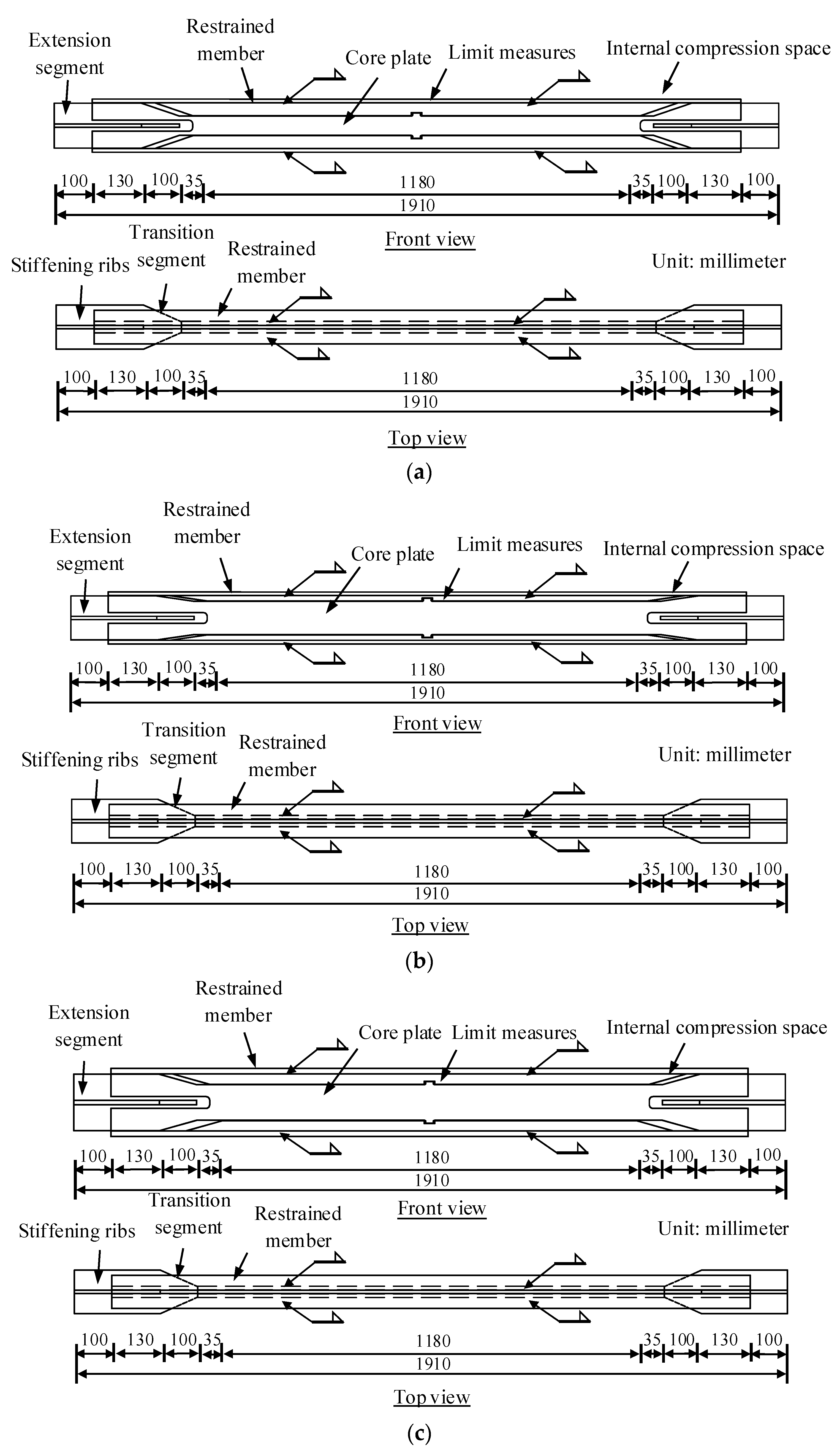
2.1. Specimen Design

The experiment involved the design of three all-steel buckling-restrained braces without unbonded materials, labeled ABRB3, ABRB5, and ABRB7. The three-dimensional structure of the braces and their components is shown in Figure 1. The outer restraining unit is a welded double-web I-beam casing. An air gap layer is created between the restraining unit and the core unit using steel spacer plates. The core plate unit adopts a rectangular cross-section, with steel spacer plates set in the strong axis direction of the core unit to prevent in-plane local buckling of the brace. Additionally, a stopper is installed in the middle of the core unit to prevent axial sliding of the restraining unit.
The core and restraining units of all three specimens were fabricated from Q235-B steel. Each specimen measured 1910 mm in length. The primary dimensions and planar configurations are illustrated in Figure 2. Detailed design parameters for each specimen’s components are provided in Table 1. The material properties of the Q235 steel (Kunming Iron & Steel Holding Co., Ltd., Kunming, China), sampled from the BRB specimen, are presented in Table 2.

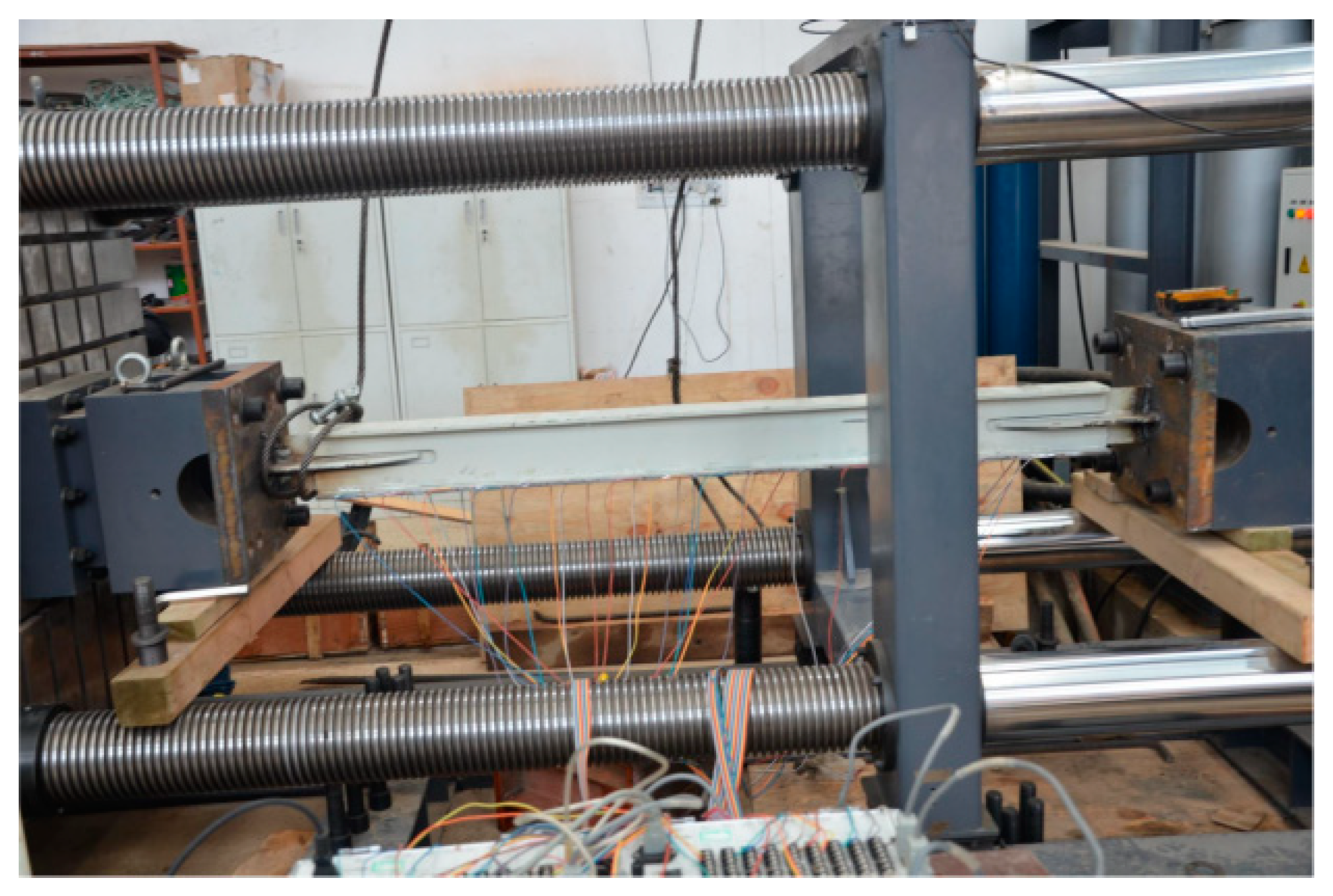
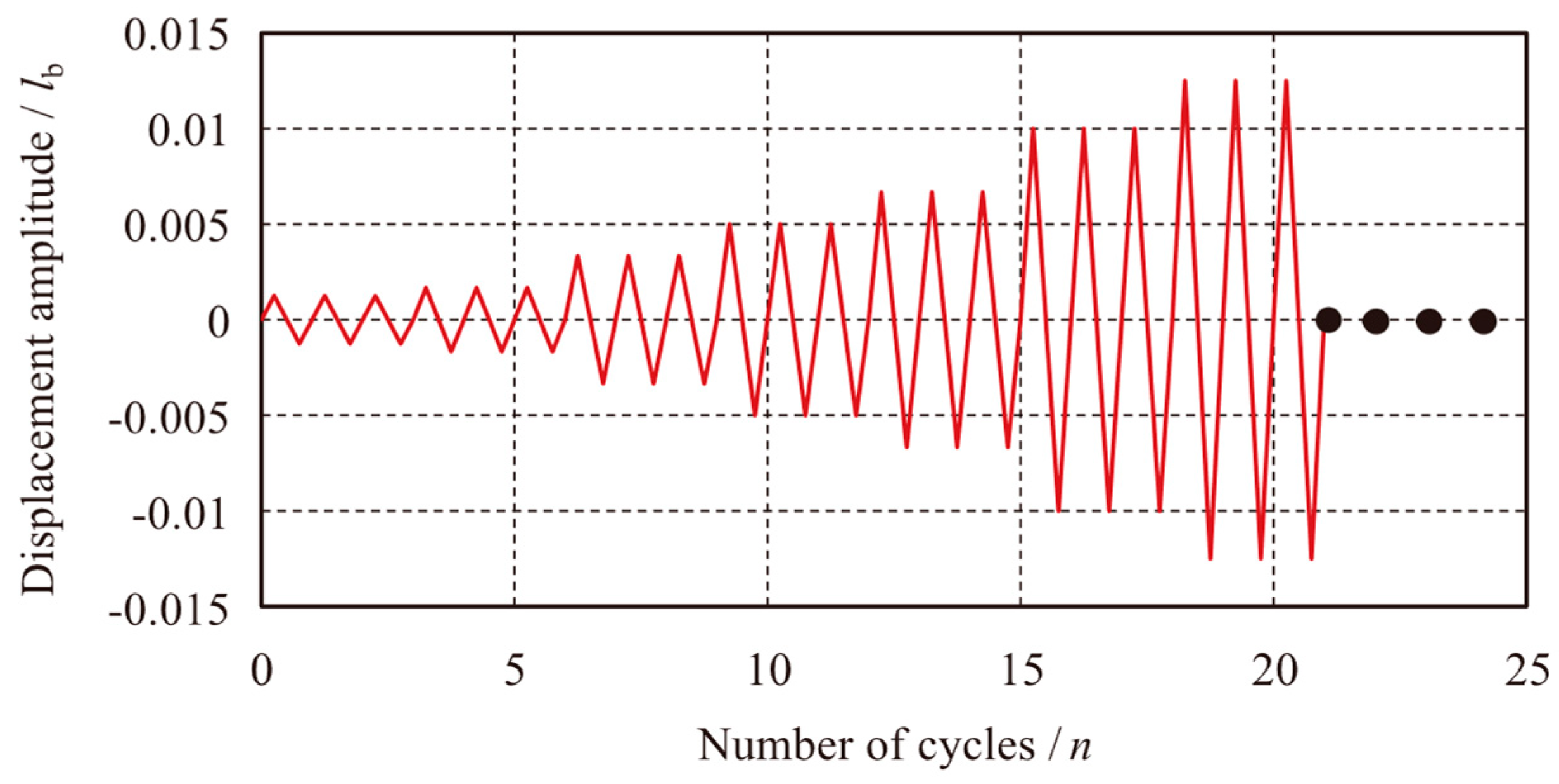
2.2. Experimental Loading and Measurement Scheme

The test was conducted using a 1500 kN electro-hydraulic servo testing machine. This machine primarily consists of an electro-hydraulic servo actuator, a directional support, and a reaction frame. The actuator has a maximum tension and compression capacity of 1500 kN, with a displacement stroke of ±250 mm. Initially, the specimen was welded to the connecting plate, which was then securely attached to the reaction support of the testing machine using high-strength bolts. The left end of the specimen was connected to the actuator, serving as the loading end. The on-site test loading setup is shown in Figure 3.
In accordance with the requirements for Buckling-Restrained Brace (BRB) performance testing outlined in the “Code for Seismic Design of Buildings” (GB 50011-2010) [22], cyclic loading tests were conducted. The tests were performed three times at strain amplitudes of (lb/800), (lb/600), (lb/300), (lb/200), (lb/150), and (lb/100) to evaluate the hysteretic behavior of the BRB under varying displacement amplitudes. Furthermore, cyclic loading was applied at a strain amplitude of (lb/80) until the specimen failed, in order to assess the low-cycle fatigue performance of the BRB. Table 3 outlines the specific loading scheme, and Figure 4 provides a schematic representation of the loading system.
The experiment mainly measures the axial load applied to the Buckling-Restrained Brace (BRB), the relative displacement between its two ends, and the strain distribution within the constraint unit along the BRB’s weak axis plane. The axial load is recorded using a force sensor mounted on the actuator, while the axial displacement is captured by wire displacement transducers symmetrically positioned on both sides of the BRB, as illustrated in Figure 5a. To investigate the relationship between the buckling behavior of the BRB core and the bending deformation of the surrounding constraint components, 16 resistive strain gauges were installed on each side of the BRB constraint unit in the weak axis direction. This configuration enables the assessment of strain distribution within the BRB constraint unit under varying displacement amplitudes, with the detailed layout of the strain gauges shown in Figure 5b.

3. Experimental Phenomena and Failure Characteristics
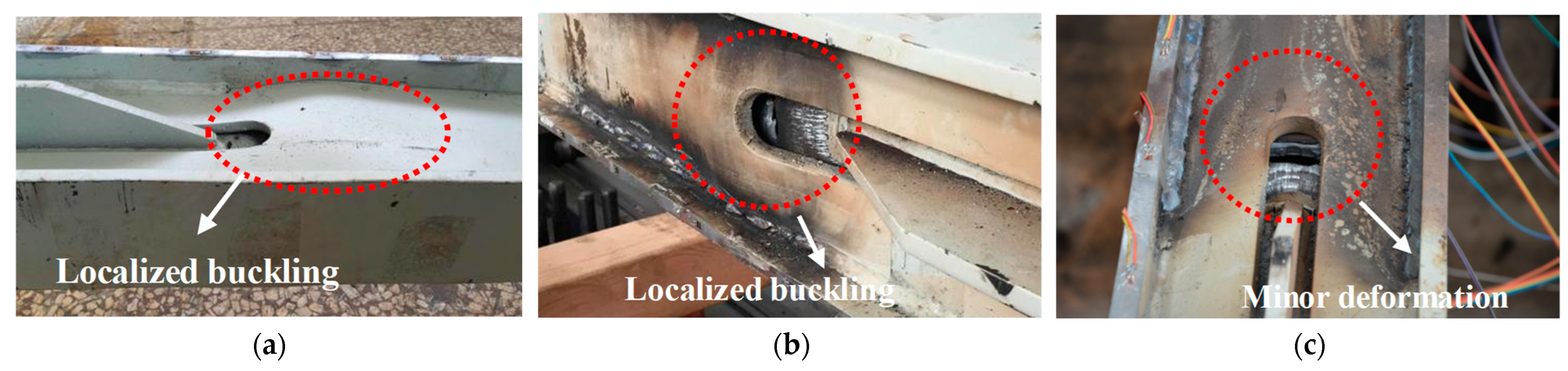
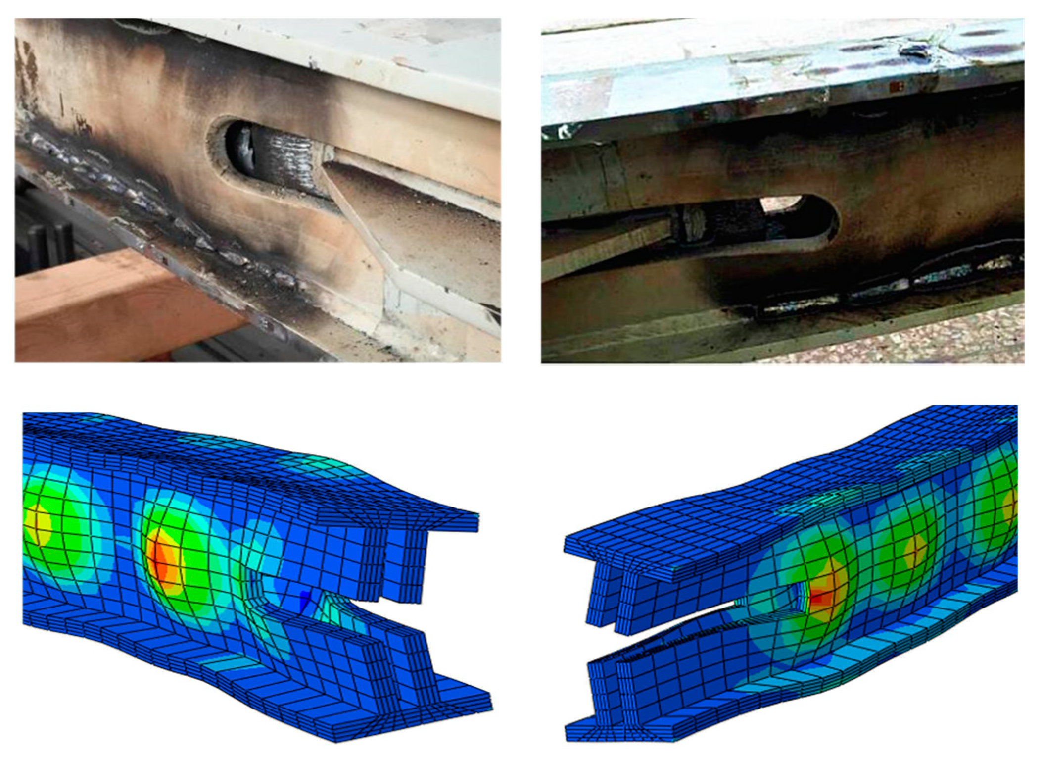
3.1. Failure Modes

During the experiment, specimens ABRB 3, ABRB 5, and ABRB 7 showed no significant changes under displacement loading amplitudes ranging from 1/800 to 1/200. For specimen ABRB 3, the constrained unit started to display slight local buckling deformation at a displacement amplitude of lb/200. When the test load reached a displacement amplitude of lb/100, obvious local bulging deformation emerged at the end of the constrained unit. At this loading level, as the number of load cycles increased, local buckling failure occurred near the loading end of the constrained unit (as depicted in Figure 6a), and the core unit fractured.
Specimen ABRB 5 suffered cyclic fracture at a displacement amplitude of lb/80. The constrained unit also showed local buckling failure near the loading end, as shown in Figure 6b. Specimen ABRB 7 also experienced cyclic fracture at a displacement amplitude of lb/80. At this stage, the constrained unit exhibited minor local buckling deformation near the loading end but generally remained in an elastic stable working state. Clear friction marks between the core unit and the surrounding constrained unit were observable, as presented in Figure 6c.
It was noted during the experiment that the local buckling positions of the constrained units in each specimen were near the BRB loading end. The reasons for this phenomenon will be further discussed and analyzed in the subsequent sections.

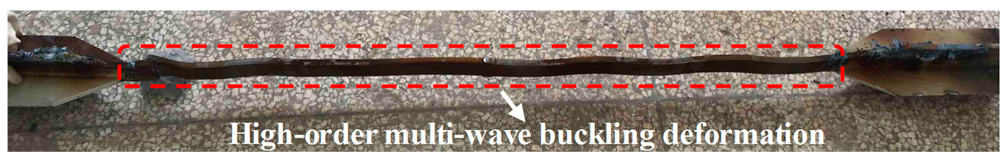
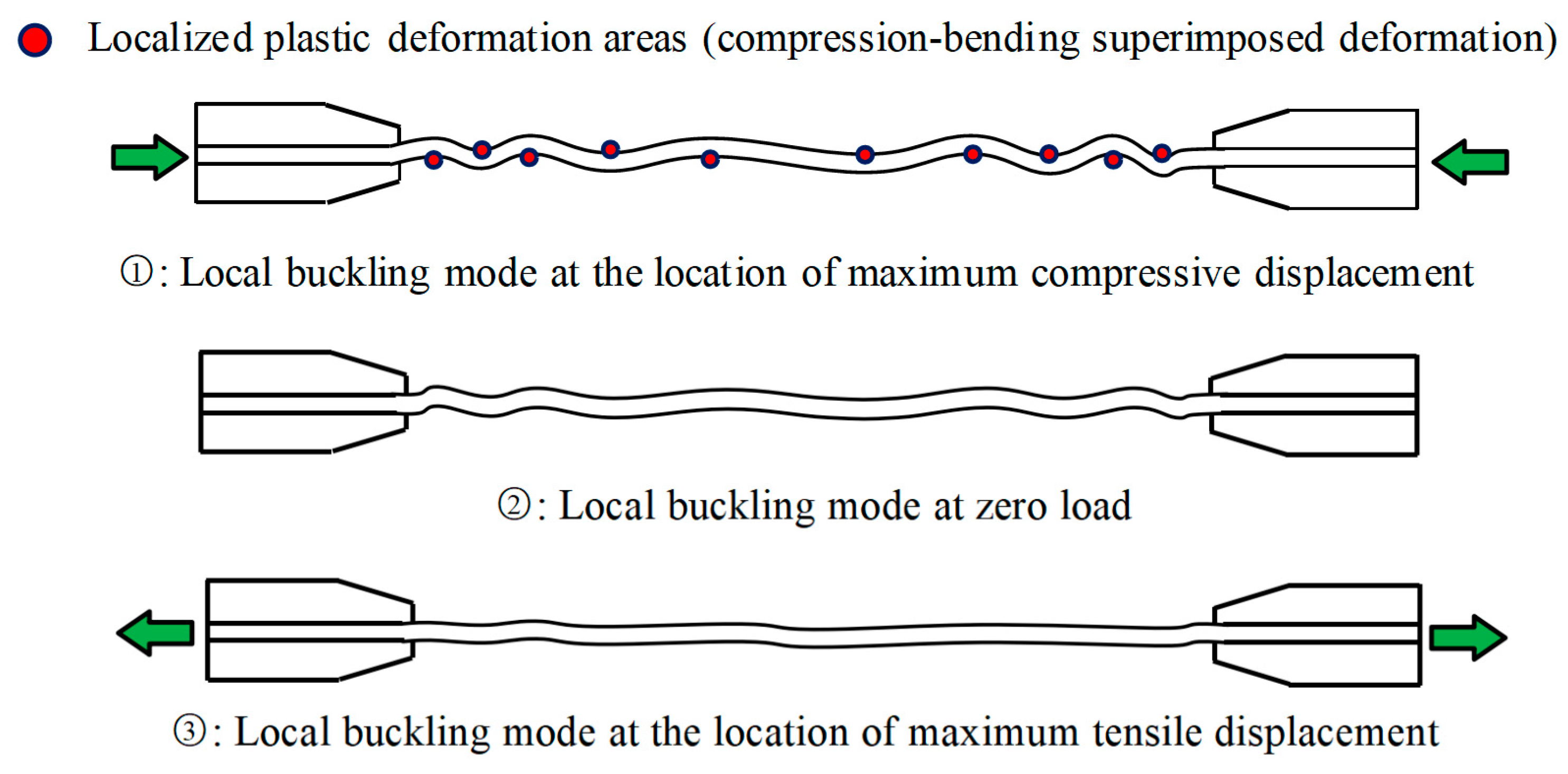
3.2. High-Order Multi-Wave Buckling of Core Energy-Consuming Unit

After removing the peripheral constraint units from each specimen at the end of the experiment, we observed that the core energy-dissipation units of each specimen exhibited significantly higher-order multi-wave buckling deformations. The typical axial higher-order multi-wave buckling deformation pattern of the energy-dissipation unit is presented in Figure 7. Moreover, the buckling amplitude near the loading end was greater than that in other locations.
This phenomenon occurs because, during compression, the axial force of the Buckling-Restrained Brace (BRB) is transmitted from the loading end to the fixed end. As the axial load increases, the energy-dissipation unit evolves from lower-order single-wave buckling at the initial axial force transmission point (the loading end) to higher-order multi-wave buckling. Dehghani, M. et al. [23] suggest that after the energy-dissipation unit enters the higher-order multi-wave buckling mode, the normal compressive force generated causes a frictional effect in the tangential direction. This results in a larger axial force at the end of the BRB (correspondingly, the local compressive force at the end is also larger), as depicted in Figure 8 [23].
The buckling amplitude of the energy-dissipation unit is positively correlated with the magnitude of the axial force. That is, the greater the axial force, the larger the corresponding local buckling amplitude. Therefore, the buckling amplitude near the loading end of the brace is greater than that in other areas, indicating that local instability is more likely to occur at the end of the constraint unit, which is consistent with the experimental observations.
Based on this analysis, the frictional interaction between the energy-dissipation unit and the constraint unit enhances the local compressive force between them to a certain degree. Hence, it is still advisable to use unbonded materials to reduce the frictional effect, thereby further enhancing the local stability performance of the brace. Additionally, attention should be focused on strengthening the design of the constraint unit’s end positions.

4. Experimental Results and Analysis

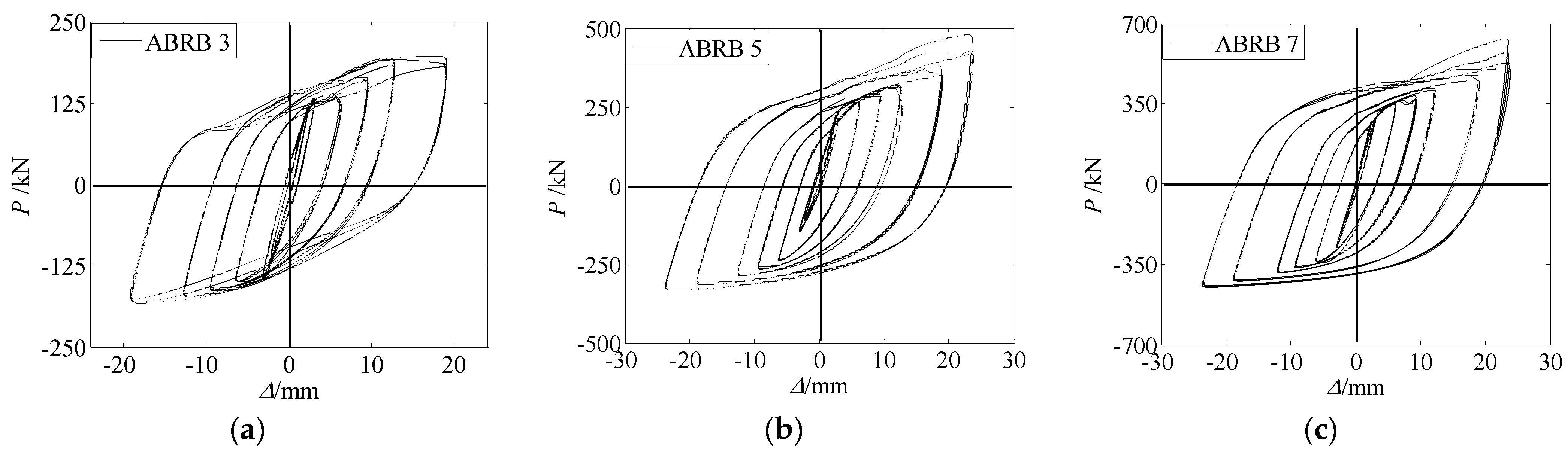
4.1. Hysteresis Curves and Characteristic Analysis

The load–displacement hysteresis curves of specimens ABRB 3, ABRB 5, and ABRB 7 are presented in Figure 9. Compression of the brace is defined as positive, and tension as negative.
For specimen ABRB 3, in the first four loading stages, the hysteresis curves of each loop under different displacement amplitudes almost overlap, suggesting that the energy-dissipation capacity of the BRB remains stable during this period, without obvious degradation in strength or stiffness. However, starting from the fifth loading stage, the hysteresis curve on the compression side starts to fluctuate. This is mainly because the multi-wave buckling of the energy dissipation unit exerts significant local pressure on the peripheral restraint components, resulting in partial instability of the restraint unit. Consequently, the energy dissipation unit fails to obtain sufficient stable compressive load-carrying capacity through the effective constraint of the restraint components, causing the hysteresis curve to fluctuate. When the load reaches lb/100, a notable degradation of strength and stiffness is observed. From the hysteresis curves, it can be seen that during this loading cycle, the loops do not overlap in both the tension and compression phases. This is because the brace undergoes large local buckling near the loading end. When the specimen is compressed in the first loading cycle, local buckling occurs. During the tension phase, the specimen cannot be fully restored, and when compressed again, due to residual deformation, more severe local buckling occurs, leading to strength and stiffness degradation.
Specimen ABRB 5 demonstrates good hysteresis energy dissipation ability in the first six loading stages, with well-overlapping hysteresis curves, indicating stable cyclic loading performance. However, as the loading displacement amplitude increases, the specimen shows some degree of tension–compression asymmetry. When the load reaches lb/100, the hysteresis curve on the compression side shows slight fluctuations. At lb/80, non-overlapping and strengthening phenomena appear near the peak compression displacement. This is mainly due to the multi-wave buckling of the energy dissipation unit, which generates significant tangential friction with the restraint components.
Specimen ABRB 7 exhibits mechanical characteristics similar to those of specimen ABRB 5 during the loading process. However, in the final loading stage, non-overlapping and strengthening phenomena also occur near the peak compression displacement in each loop.

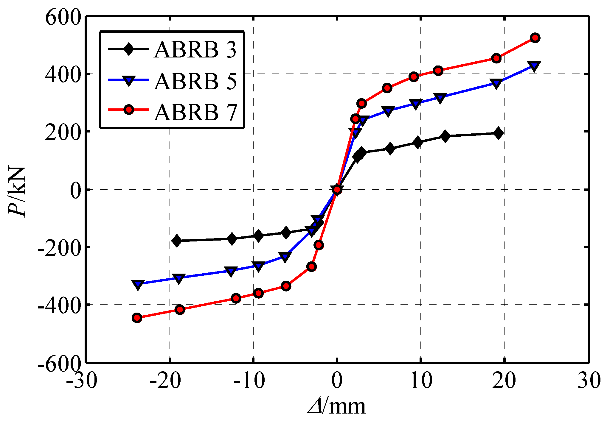
4.2. Skeleton Curves and Characteristic Analysis

Figure 10 presents the skeleton curves of specimens ABRB 3, ABRB 5, and ABRB 7 under low-cycle reciprocating loads. The figure illustrates that all three specimens exhibit a distinct yield point as they transition from the elastic phase to the plastic hardening phase. The overall curve clearly exhibits a bilinear restoring-force characteristic. This indicates that a bilinear model can be used in finite-element analysis to simulate the hysteretic behavior of all-steel buckling-restrained braces without an unbonded layer. Moreover, the skeleton curves indicate that the yield load under compression is greater than that under tension for each specimen. This discrepancy is attributed to the Bauschinger effect [24] in steel and the substantial frictional force generated between the energy-dissipating unit and the restraining unit after repeated buckling deformation.

4.3. Imbalance Coefficient of Tensile and Compressive Bearing Capacity

The tension–compression imbalance factor β represents the peak load difference of the buckling-restrained brace (BRB) under tension and compression loading. This factor is defined as the ratio of the maximum compressive load Pcmax to the maximum tensile load Ptmax in the hysteresis curves of each cycle of the BRB. According to the Technical Code for “Steel Structures of High-Rise Civil Buildings” (JGJ 99-2015) [25], hereinafter referred to as the High Steel Code, the coefficient β must not exceed 1.3.
The specimens ABRB 3, ABRB 5, and ABRB 7 exhibited an imbalance coefficient β distribution ranging from 0.89 to 1.3 under the first six loading levels. The occurrence of β values less than 1 in specimen ABRB 3 was attributed to local buckling phenomena in the BRB during compression. Specimen ABRB 5 surpassed the limit value for the imbalance coefficient under the lb/80 loading strain amplitude, as specified in the High Steel Code. This phenomenon was attributed to considerable friction between the energy-dissipating components and the restraining components resulting from multi-wave buckling deformation under compression. An additional phenomenon was observed in specimen ABRB 7 during the lb/80 fatigue loading phase. The compressive cyclic hardening effect became more pronounced with an increasing number of load cycles, leading to an increase in the tension–compression bearing capacity imbalance coefficient β, with a maximum value reaching 1.79, significantly exceeding the requirements of the High Steel Code. This was primarily due to the energy-dissipating unit undergoing multi-wave buckling deformation under compression, resulting in compressive bending deformation at the wave peaks and troughs. When the brace is under tension, the residual compressive bending deformation cannot be fully restored to a straight state. Upon subsequent compression of the energy-dissipating unit, greater local buckling deformation occurs at the same locations, further increasing the friction between the energy-dissipating unit and the restraining components [26]. To ensure stable hysteretic performance of the BRB under cyclic loading, it is recommended to use unbonded materials to reduce friction effects, thereby maintaining the BRB tension–compression bearing capacity imbalance coefficient within a reasonable range.

4.4. Equivalent Viscous Damping Ratio

Buckling-restrained braces are categorized as displacement-type energy dissipation devices. Their energy dissipation capacity is quantified using the equivalent viscous damping ratio. Due to the asymmetry in the hysteresis curves observed under tension and compression for each specimen, the hysteresis curves for positive loading (compression) and negative loading (tension) are computed separately. The specific calculation method follows the guidelines outlined in JGJ/T 101-2015 [27], “Technical Specification for Seismic Test of Buildings”. The relevant calculation formulas are provided in Equations (1) and (2), and a schematic representation of the calculation is depicted in Figure 11.
ζ eq + = 1 2 π S AGH S OAB
ζ eq = 1 2 π S DGH S OCD
In these formulas, SOAB and SOCD denote the areas of the shaded triangles in Figure 11, while SAGH and SDGH represent the areas of the upper and lower halves of the hysteresis loop in Figure 11.
Figure 12 depicts the distribution of the equivalent viscous damping ratio for each specimen. From the figure, it is evident that the equivalent viscous damping ratio rises with the amplitude of axial loading displacement. The maximum values of this parameter for specimens ABRB 3, ABRB 5, and ABRB 7 are 39.3%, 42.5%, and 43.2%, respectively. Additionally, it is observed that the values during the tensile cycle are slightly lower than those during the compressive cycle. This is primarily because of the friction effect generated in the brace during compression, which enhances the energy-dissipation capacity of the component. As the axial displacement increases to a certain degree, the increase in its value tends to plateau.

4.5. Equivalent Stiffness

Figure 13 illustrates the variation in secant stiffness, also known as equivalent stiffness, with loading displacement for each test specimen. Due to the asymmetrical tensile and compressive bearing capacities of the Buckling-Restrained Brace (BRB), the secant stiffness was calculated separately for tension and compression, following the method prescribed in JGJ/T 101-2015, “Specifications for Seismic Testing of Buildings”. The figure demonstrates that the tensile and compressive stiffness of the three specimens are generally symmetrically distributed. The overlap of secant stiffness across various displacement amplitude cycles is substantial, indicating that the mechanical performance of the braces under cyclic loading is relatively stable. However, as the loading displacement amplitude increases, the secant stiffness under tensile and compressive cyclic loading exhibits increasing asymmetry. This is primarily attributed to friction effects, as previously analyzed. Additionally, at smaller loading displacement amplitudes, the secant stiffness decreases rapidly, whereas at larger displacements, the rate of decline becomes more gradual.

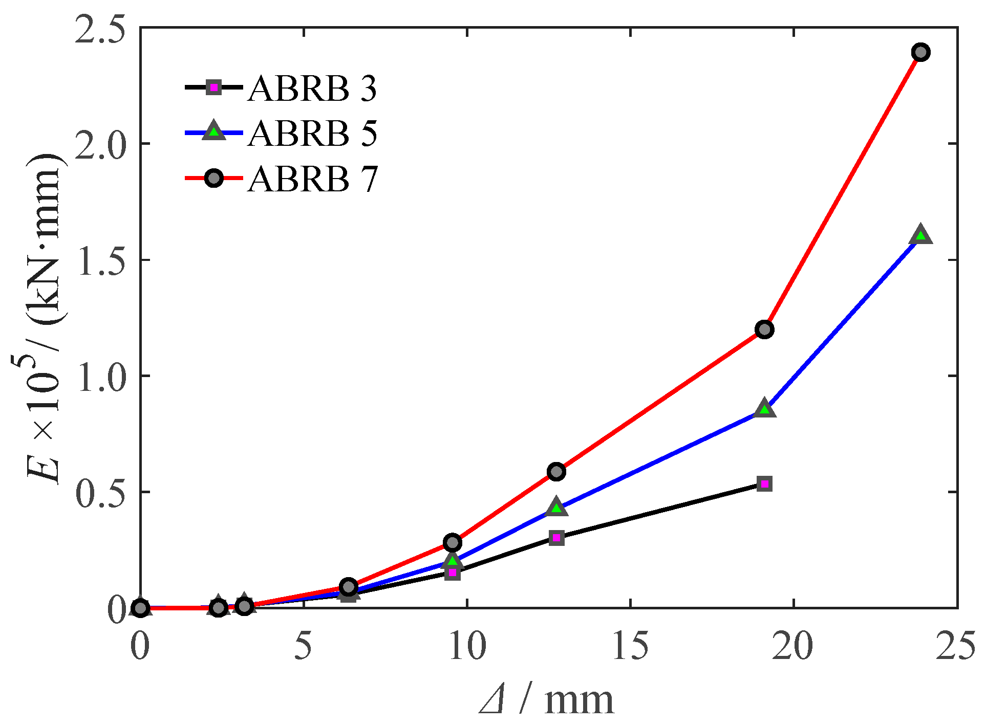
4.6. Cumulative Hysteresis Energy Dissipation Capacity

Cumulative hysteretic energy dissipation capacity is one of the key indicators for evaluating the seismic performance of buckling-restrained braces (BRBs). Figure 14 illustrates the relationship between cumulative hysteretic energy dissipation and loading displacement for specimens ABRB 3, ABRB 5, and ABRB 7. It can be observed from the figure that the cumulative energy dissipation of each specimen increases with the increase in loading displacement, indicating that each specimen has a sustained and steadily growing hysteretic energy dissipation capacity. Under various levels of loading displacement amplitudes, the cumulative hysteretic energy dissipation capacity of specimens ABRB 3, ABRB 5, and ABRB 7 increases sequentially, with their maximum cumulative hysteretic energy dissipation values being 53.57 kN·m, 160.01 kN·m, and 239.35 kN·m, respectively. Additionally, as the loading displacement amplitude increases, the differences in energy dissipation capacity among the specimens become more pronounced.

4.7. Low-Cycle Fatigue Performance

Figure 15 presents the low-cycle fatigue curves for specimens ABRB 5 and ABRB 7 under a loading displacement amplitude of lb/80, with ABRB 3 fracturing at a displacement amplitude of lb/100. The figure reveals that the hysteresis loops of both specimens fluctuate under cyclic loading. On the compression side of the curve, from the initial to the final loading cycle, a distinct strengthening phenomenon is evident near the maximum displacement. This phenomenon, previously analyzed in earlier sections, is primarily attributed to the increase in residual compressive bending deformation at multiple buckling peaks and troughs of the buckling-restrained brace (BRB) under repeated cyclic loading. Even when the brace is fully tensioned, it remains partially unstraightened, resulting in significant friction between the energy-dissipating unit and the restraining component, thereby contributing to the observed strengthening phenomenon. Figure 16 illustrates the local buckling deformation patterns of the core energy-dissipating unit at several key positions: maximum compressive displacement, maximum tensile displacement, and zero load [28]. This analysis suggests that the fatigue performance of all-steel buckling-restrained braces without unbonded materials is insufficiently stable.
Specimen ABRB3 experienced fracture failure at a displacement amplitude of lb/100, without entering the fatigue loading phase of the test. As shown in Figure 15, the low-cycle fatigue loading cycles of specimens ABRB 5 and ABRB 7 at a displacement amplitude of lb/80 were both below the theoretical fatigue life. The main reason for this is that during compression, the Buckling Restrained Brace (BRB) exhibited higher-order multi-wave buckling deformation. Since fatigue failure of the specimen begins at the location of maximum strain, at the position of local buckling of the steel core, the final deformation consists of two parts: compressive deformation and bending deformation. Therefore, the strain at this location is the sum of compressive strain and bending strain. This local strain is significantly larger than the axial average strain, whereas theoretical fatigue life is typically calculated based on the axial average strain. Consequently, the actual fatigue life of the BRB is lower than the theoretical fatigue life.

4.8. Cumulative Plastic Deformation Capacity

The cumulative plastic deformation capacity is an important indicator for evaluating the performance of buckling-restrained braces (BRBs). Takeuchi T. et al. [29] proposed a unified assessment model and prediction method for the cumulative plastic deformation capacity at the point of BRB fracture under different cyclic loading patterns. This method decomposes the BRB hysteresis curve into the “skeleton part”, “Bauschinger part”, and “elastic unloading part”. The “skeleton part” corresponds to the hysteresis curve when a certain load level is first reached during loading; the “Bauschinger part” corresponds to the hysteresis curve when a previously experienced load level is reached again; and the “elastic unloading part” corresponds to the curve during the unloading process. Takeuchi et al. argue that the “skeleton part” and “Bauschinger part” contribute differently to the damage of BRBs. The prediction model for cumulative plastic strain, denoted as Σεp, at BRB fracture, as proposed by these researchers, is provided in Equation (3).
ε p = 1 α S 35 + ( 1 α S ) ( ε a 0.41 417.14 )
In the formula, αS represents the ratio of the cumulative plastic strain of the “framework part” (ΣεpS) to the total cumulative plastic strain (Σεp), expressed as αS = ΣεpS/(ΣεpS + ΣεpB); εa is the mean strain amplitude during the loading process.
Figure 17a illustrates the relationship between the cumulative plastic strain Σεp and αS for specimens ABRB 3, ABRB 5, and ABRB 7, derived by decomposing the hysteresis curves using the method proposed by Takeuchi et al. Figure 17b compares the cumulative plastic strain Σεp predicted by Equation (3) with the experimental results Σεp for each specimen. The figure reveals that ABRB 7 demonstrates the highest prediction accuracy, although it is lower than that achieved with the same prediction model in [30]. An analysis of the experimental results indicates that prediction accuracy is inversely correlated with the extent of local buckling deformation in the BRB energy dissipation unit. Specifically, greater local buckling deformation corresponds to lower prediction accuracy. Examination of prediction Formula (3) reveals that the parameter εa represents the average strain amplitude during loading. However, after local buckling deformation of the BRB energy dissipation unit, the deformation at peaks and valleys is a combination of compressive and bending deformations. This superposition effect results in local strains at peaks and valleys exceeding the average axial strain when only compressive deformation is considered. Particularly when significant local instability occurs due to large BRB deformations, local strains substantially exceed the average strain. Consequently, using Equation (3) to predict the plastic deformation capacity of the BRB underestimates the strain amplitude experienced. Therefore, the predicted cumulative plastic strain Σεp exceeds the experimental value Σεp, which explains why ABRB 7 shows the highest prediction accuracy among the three specimens.

5. Finite Element Analysis

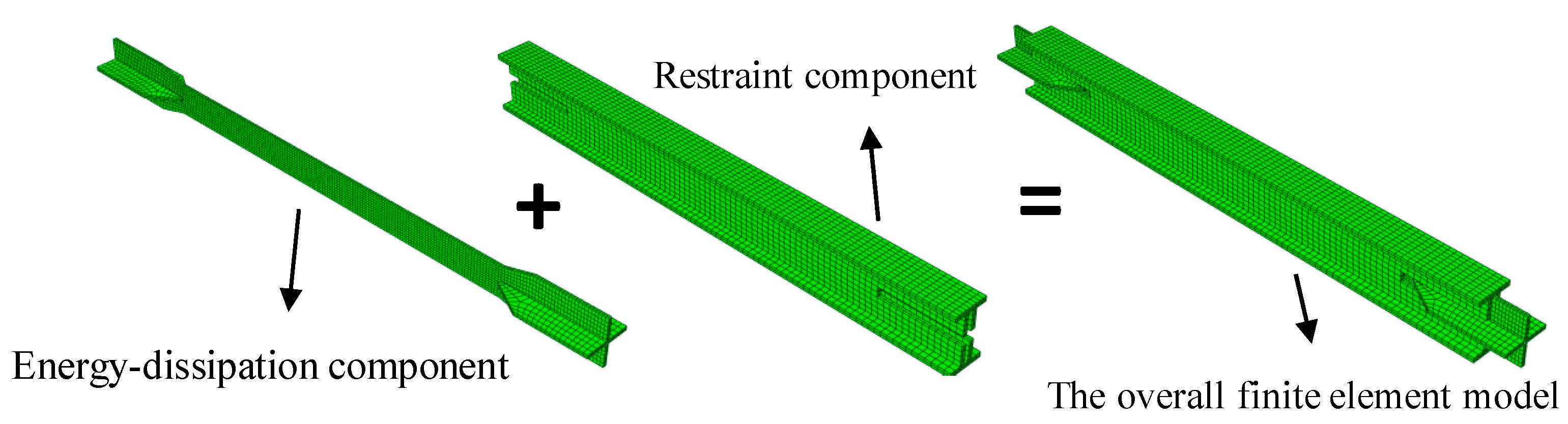
5.1. Finite Element Model Development

A finite element model of the three experimental specimens was established using the large general-purpose finite element software ABAQUS (V 6.14). The geometric parameters, materials, and loading protocols of the three finite element models were consistent with those of the experimental specimens described earlier. The finite element models were constructed using solid elements C3D8R, and the material constitutive behavior was modeled using ABAQUS’s built-in constitutive model for metals under cyclic loading. The mesh size was determined through trial calculations, with the energy-dissipating component having an element size of 10 mm and the constraining component having an element size of 20 mm in the longitudinal direction. Hard contact properties were set in the normal direction between the energy-dissipating and constraining components, while frictional contact properties were set in the tangential direction, with a friction coefficient of 0.3. The finite element model is shown in Figure 18.

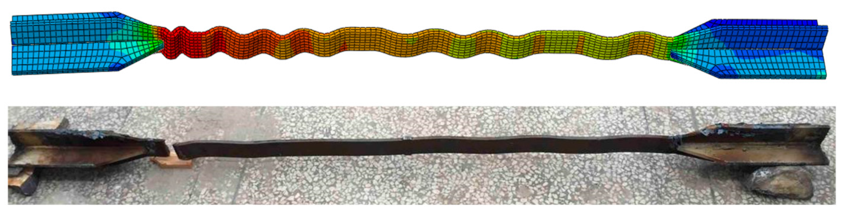
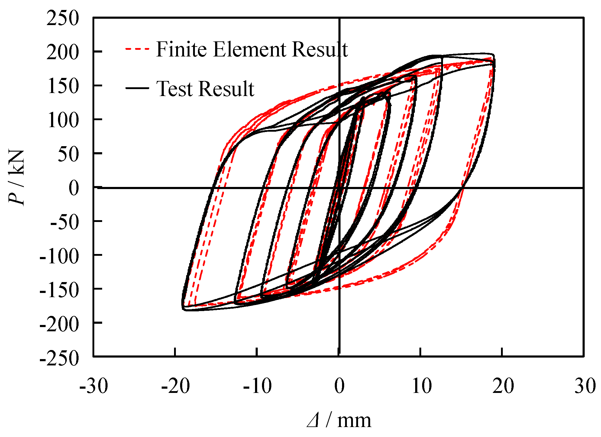
5.2. Analysis of Finite Element Simulation Results

The analysis of the refined finite element model under low-cycle repeated loading was conducted, and Figure 19 shows a comparison between the typical BRB energy dissipation segment’s higher-order multi-wave buckling deformation mode obtained from the finite element analysis and the experimental results. From the figure, it can be observed that the deformation mode obtained from the finite element analysis is generally consistent with the experimental results. The final failure location is also near the end of the side where the support load is applied. The finite element results are in high agreement with the experimental findings, indicating that finite element analysis can effectively predict the higher-order deformation modes and fracture failure locations of BRBs.
Figure 20 presents a comparison between the deformation pattern of a typical Buckling-Restrained Brace (BRB) constrained steel casing and the experimental results. It can be observed from the figure that local buckling occurs at the end of the constrained steel casing near the loading side of the brace. The stress distribution cloud map indicates that the contact force between the energy dissipation unit and the constrained steel casing is greater at the end compared to locations further from the end, and it exhibits a decreasing trend in the direction away from the loading end. The finite element analysis results show a high degree of agreement with the experimental results, with the locations of local buckling being largely consistent with the experimental findings. This indicates that finite element analysis is effective in predicting the deformation pattern and local buckling position of BRB-constrained steel casings.
Figure 21 presents a comparison between the typical hysteresis curves of the BRB obtained through finite element analysis (FEA) and experimental results. The figure indicates that the FEA results for the yield load capacity and the ultimate load capacity of the BRB are in close agreement with the experimental data. The hysteresis curves derived from FEA closely overlap with the experimental curves, demonstrating that the finite element model is accurate and reliable. Additionally, the initial elastic stiffness and post-yield stiffness curves of the BRB simulated via FEA are well aligned with the experimental findings. Furthermore, the FEA-derived hysteresis curve effectively captures the strengthening characteristics of the steel under cyclic loading, including the in-phase and out-of-phase enhancement behaviors.

6. Conclusions

This study conducted low-cycle reciprocating load performance tests and finite element numerical simulations on three all-steel buckling-restrained braces lacking unbonded materials. It examined the effects of the absence of an unbonded layer on several performance indicators of BRBs, including failure modes, energy dissipation capacity, cumulative plastic deformation capacity, and low-cycle fatigue life. The conclusions derived from the study are as follows:
(1)
Due to friction effects, the axial force distribution along the length of all-steel BRBs without unbonded material exhibits a gradient, with higher forces at the ends and lower forces in the middle. Consequently, the buckling wavelength of the energy dissipation unit is shorter near the ends and longer in the middle. Experimental results suggest that this type of BRB is more susceptible to localized instability failures at its ends.
(2)
Excessive friction between the energy dissipation and constraint units in BRBs without unbonded material increases local compressive stress, adversely affecting local stability. Additionally, the fatigue performance of these BRBs is inconsistent. For instance, due to friction effects, the tensile-to-compressive strength imbalance coefficient of specimen ABRB 7 reached 1.79, exceeding standard limits.
(3)
Test results from specimens ABRB 3, ABRB 5, and ABRB 7 indicate a negative correlation between fatigue performance and the amplitude of local buckling in the energy dissipation unit. Specifically, excessive friction effects can, to a certain extent, reduce the fatigue performance of BRBs.
(4)
In conclusion, the use of unbonded materials in the design of all-steel BRBs is recommended to mitigate friction effects, improve local stability, maintain acceptable imbalance coefficients, and enhance fatigue performance.

Author Contributions

Conceptualization, K.W. and G.W.; methodology, L.Z.; software, W.Y.; validation, W.Y., X.L. and L.Z.; formal analysis, K.W.; investigation, K.W.; resources, G.W.; data curation, L.Z.; writing—original draft preparation, K.W.; writing—review and editing, G.W.; visualization, G.W.; supervision, W.Y.; project administration, X.L.; funding acquisition, L.Z. All authors have read and agreed to the published version of the manuscript.

Funding

This research was supported by Yunnan Fundamental Research Projects (grant NO. 202501AT070066), Special Basic Cooperative Research Programs of Yunnan Provincial Undergraduate Universities’ Association (grant NO. 202101BA070001-176, 202101BA070001-159), Scientific Research Fund Project of the Yunnan Provincial Department of Education (Grant No. 2025J1150), Project of the Scientific Research Characteristic Team for Research and Application of Seismic Isolation and Mitigation Technologies in High-Intensity Areas (No. XJ20230036).

Data Availability Statement

All the data utilized in the research have been fully presented in the paper. No additional data have been employed.

Conflicts of Interest

The authors declare no conflicts of interest.

References

  1. Guo, Y.L.; Tong, J.Z.; Zhou, P. Research progress of buckling restrained braces: Types, design methods and applications. Eng. Mech. 2016, 33, 1–14. (In Chinese) [Google Scholar]
  2. Gao, J.; Xu, Z.G.; Ren, C.C.; Xue, Y.T.; Chen, J.K.; Yue, C.L.; Wang, L. Beijing rail transit command center (phase II) energy dissipation technology and dynamic elasto-plastic analysis. J. Build. Struct. 2014, 35, 56–62. (In Chinese) [Google Scholar]
  3. Ma, J.L.; Zhang, L.X.; Chen, Y.S. The future developing trends of buckling restrained braces from the 16WCEE. Earthq. Eng. Eng. Vib. 2017, 37, 127–135. (In Chinese) [Google Scholar]
  4. He, Y.T.; Ding, S.W.; Tu, T.G. Research progress and application development of buckling-restrained brace for seismic member. Spec. Struct. 2022, 39, 17–27+34. (In Chinese) [Google Scholar]
  5. Zhou, Y.; Zhong, G.Q.; Chen, Q.X.; Gong, C. Experimental study on hysteretic performance of steel-plate assembled buckling-restrained braces with different constructional details. China Civ. Eng. J. 2017, 50, 9–17. (In Chinese) [Google Scholar]
  6. Yan, H.; Pan, P.; Wang, Y.Q.; Muye, J.X.; Qi, X. Experimental study of buckling-restrained braces with in-line steel core plate encased in double web wide flange steel outer unit. J. Build. Struct. 2012, 33, 142–149. (In Chinese) [Google Scholar]
  7. Guo, Y.L.; Zhang, B.H.; Zhu, B.L. Restrain ratio of all-steel core-separated buckling-restrained braces. J. Build. Struct. 2015, 36, 133–141. (In Chinese) [Google Scholar]
  8. Chen, Q.; Li, T.; Wang, C.L.; Meng, S.P. Experimental research on effect of unbonding material on mechanical behavior of all-steel buckling-restrained brace. J. Build. Struct. 2013, 34, 119–124. (In Chinese) [Google Scholar]
  9. Zhao, J.X.; Wu, B.; Ou, J.P. Uniaxial quasi-static cyclic tests on the hysteretic behavior of a novel type of all-steel buckling-restrained brace. China Civ. Eng. J. 2011, 44, 60–70. (In Chinese) [Google Scholar]
  10. Huang, B.; Chen, Q.; Li, T.; Wang, C.L.; Wu, J. Low-cycle fatigue test of Q235 steel buckling-restrained braces. China Civ. Eng. J. 2013, 46, 29–34, 43. (In Chinese) [Google Scholar]
  11. Yang, L.; Wei, X.; Shi, G.; Xiao, S.Y. Experiment on energy dissipation performance of LY315 steel buckling-restrained braces. Eng. Mech. 2019, 36, 200–206. (In Chinese) [Google Scholar]
  12. Wang, J.J.; Shi, Y.J.; Yan, H.; Wang, Y.Q.; Pan, P. Experimental study on the seismic behavior of all-steel buckling-restrained brace with low yield point. China Civ. Eng. J. 2013, 46, 9–16+25. (In Chinese) [Google Scholar]
  13. Das, P.J.; Deb, S.K. Seismic performance evaluation of a new hybrid buckling restrained brace under cyclic loading. J. Struct. Eng. 2022, 148, 0003372. [Google Scholar] [CrossRef]
  14. Dehghani, M.; Tremblay, R. Design and full-scale experimental evaluation of a seismically endurant steel buckling-restrained brace system. Earthq. Eng. Struct. Dyn. 2018, 47, 105–129. [Google Scholar] [CrossRef]
  15. Tremblay, R.; Bolduc, P.; Neville, R.; DeVall, R. Seismic testing and performance of buckling-restrained bracing systems. Can. J. Civ. Eng. 2006, 33, 183–198. [Google Scholar] [CrossRef]
  16. Iwata, M. Applications-design of buckling restrained braces in Japan. In Proceedings of the 13th World Conference on Earthquake Engineering, Vancouver, BC, Canada, 1–6 August 2004; Canadian Association for Earthquake Engineering: Vancouver, BC, Canada, 2004; p. 3028. [Google Scholar]
  17. Wang, C.L.; Usami, T.; Funayama, J. Improving low-cycle fatigue performance of high-performance buckling-restrained braces by toe-finished method. J. Earthq. Eng. 2012, 16, 1248–1268. [Google Scholar] [CrossRef]
  18. Wu, A.C.; Lin, P.C.; Tsai, K.C. High-mode buckling responses of buckling-restrained brace core plates. Earthq. Eng. Struct. Dyn. 2014, 43, 375–393. [Google Scholar] [CrossRef]
  19. Lu, H.F.; Chen, B.K. Research status and engineering application of buckling-restrained braces. Constr. Technol. 2019, 48, 1292–1296. (In Chinese) [Google Scholar]
  20. Takeuchi, T.; Wada, A. Buckling-Restrained Braces and Applications; The Japan Society of Seismic Isolation: Tokyo, Japan, 2017. [Google Scholar]
  21. Genna, F.; Gelfi, P. Analysis of the lateral thrust in bolted steel buckling-restrained braces. I: Experimental and numerical results. J. Struct. Eng. 2012, 138, 1231–1243. [Google Scholar] [CrossRef]
  22. GB 50011-2010; Code for Seismic Design of Buildings. China Architecture & Building Press: Beijing, China, 2010.
  23. Dehghani, M.; Tremblay, R. An analytical model for estimating restrainer design forces in bolted buckling-restrained braces. J. Constr. Steel Res. 2017, 138, 608–620. [Google Scholar] [CrossRef]
  24. Wu, K.; Wei, G.; Lin, C.; Zhang, L.; Yu, W.; Lan, X. Experimental Study on the Seismic Performance of Buckling-Restrained Braces with Different Lengths. Buildings 2025, 15, 154. [Google Scholar] [CrossRef]
  25. JGJ 99-2015; Technical Specification for Steel Structure of Tall Building. China Architecture & Building Press: Beijing, China, 2015.
  26. Lin, P.; Tsai, K.; Chang, C.; Hsiao, Y.; Wu, A. Seismic design and testing of buckling-restrained braces with a thin profile. Earthq. Eng. Struct. Dyn. 2016, 45, 339–358. [Google Scholar] [CrossRef]
  27. JGJ/T 101-2015; Specification for Seismic Test of Buildings. China Architecture & Building Press: Beijing, China, 2015.
  28. Zhao, J.X.; Wu, B.; Ou, J.P. Local buckling behavior of steel angle core members in buckling-restrained braces: Cyclic tests, theoretical analysis, and design recommendations. Eng. Struct. 2014, 66, 129–145. [Google Scholar] [CrossRef]
  29. Takeuchi, T.; Ida, M.; Yamada, S.; Suzuki, K. Estimation of cumulative deformation capacity of buckling restrained braces. J. Struct. Eng. 2008, 134, 822–831. [Google Scholar] [CrossRef]
  30. Qu, Z.; Xie, J.; Cao, Y.; Li, W.; Wang, T. Effects of strain rate on the hysteretic behavior of buckling-restrained braces. J. Struct. Eng. 2020, 146, 06019003. [Google Scholar] [CrossRef]
Figure 1. Three-dimensional structure schematic of BRB.
Buildings 15 01626 g001
Figure 2. Geometric dimension diagram of BRB. (a) Specimen ABRB 3; (b) Specimen ABRB 5; (c) Specimen ABRB 7.
Buildings 15 01626 g002
Figure 3. Experimental loading site diagram.
Buildings 15 01626 g003
Figure 4. Diagram of the loading system.
Buildings 15 01626 g004
Figure 5. Displacement measurement of BRB and strain gauge layout of restraint segment: (a) displacement gauge arrangement; (b) strain gauge arrangement of the restraint segment.
Buildings 15 01626 g005
Figure 6. Failure characteristics and mode of BRBs: (a) specimen ABRB 3; (b) specimen ABRB 5; (c) specimen ABRB 7.
Buildings 15 01626 g006
Figure 7. Typical high-order multi-wave buckling deformation of BRB core units.
Buildings 15 01626 g007
Figure 8. Diagram of the force interaction between the energy-consuming unit and the constraint unit during the compression stage.
Buildings 15 01626 g008
Figure 9. Load–displacement hysteresis curves of BRBs: (a) specimen ABRB 3; (b) specimen ABRB 5; (c) specimen ABRB 7.
Buildings 15 01626 g009
Figure 10. Skeleton curves of BRBs.
Buildings 15 01626 g010
Figure 11. Calculation of the equivalent viscous damping ratio.
Buildings 15 01626 g011
Figure 12. Equivalent viscous damping ratio.
Buildings 15 01626 g012
Figure 13. Stiffness degradation curves.
Buildings 15 01626 g013
Figure 14. Cumulative hysteresis energy dissipation curve.
Buildings 15 01626 g014
Figure 15. Low-cycle fatigue curves of BRBs: (a) specimen ABRB 5; (b) specimen ABRB 7.
Buildings 15 01626 g015
Figure 16. Local buckling deformation of core plate at key position.
Buildings 15 01626 g016
Figure 17. Comparison between experimental and predicted value: (a) ΣεpαS relationship curve; (b) relationship between Σεp and Σεp [30].
Buildings 15 01626 g017
Figure 18. Finite element model.
Buildings 15 01626 g018
Figure 19. Comparison of typical high-order multi-wave buckling deformation modes in BRB.
Buildings 15 01626 g019
Figure 20. Comparison of typical deformation patterns of BRB-constrained steel casings.
Buildings 15 01626 g020
Figure 21. Hysteresis loop comparison of BRBs.
Buildings 15 01626 g021
Table 1. Dimension parameters of BRBs.
Specimen NumberBrace Total Length
lb/mm
Internal Structural CompositionOuter Restraint Unit
Energy Dissipation SegmentTransition SegmentConnection SegmentWeb PlateFlange
lc/mmbc/mmtc/mmAc/mm2lt/mmll/mmAl/mm2br/mmtr/mmbf/mmtf/mm
ABRB 319101250511051013523014281221010210
ABRB 519101250901090013523025201221010210
ABRB 7191012509612115213523032261541511415
Note: Ac, Al represent the cross-sectional areas of the energy dissipation and connection segments, respectively. lc, lt, ll denote the lengths of the energy dissipation, transition, and connection segments, respectively. bc, tc are the width and thickness of the energy dissipation segment. bf, tf are the width and thickness of the flange of the restraint component. br, tr are the width and thickness of the web of the restraint component.
Table 2. The mechanical properties of Q235 steel.
Sample NumberYield Strength
fy/MPa
Tensile Strength
fu/MPa
Elastic Modulus
Es/MPa
Elongation
A/%
12894261.96 × 10527.3
22934301.98 × 10523.4
33054512.02 × 10526.9
Average2964361.99 × 10525.9
Table 3. Details of test loading scheme.
Load Control ModeLoading LevelStrain Amplitude
εA/%
Displacement Amplitude ∆A/mmThe Number of Cycles/n
Displacement control10.132.393
20.173.183
30.336.373
40.509.553
50.6712.733
61.0019.103
71.2523.88
Note: In the table, “—” indicates that cyclic loading continued until the specimen fractured.
Disclaimer/Publisher’s Note: The statements, opinions and data contained in all publications are solely those of the individual author(s) and contributor(s) and not of MDPI and/or the editor(s). MDPI and/or the editor(s) disclaim responsibility for any injury to people or property resulting from any ideas, methods, instructions or products referred to in the content.

