Article

On the Penetration of Projectiles into Semi-Infinite Concrete Targets in a Coupled Deforming and Eroding Regime

by
Hengwei Xu
,
Yonggang Lu
,
Junrun Li
,
Xing Chen
,
Xiaowei Feng
and
Zhengcao Lu
*
Institute of Systems of Engineering, China Academy of Engineering Physics, Mianyang 621900, China
*
Author to whom correspondence should be addressed.
Buildings 2025, 15(10), 1607; https://doi.org/10.3390/buildings15101607
Submission received: 5 March 2025 / Revised: 28 March 2025 / Accepted: 10 April 2025 / Published: 10 May 2025
(This article belongs to the Section Building Structures)

Abstract

:
With the advancement of high-velocity kinetic energy weapons, the impact velocity encountered by concrete protective structures has evolved from low to high velocity ranges, rendering traditional rigid projectile penetration theories inadequate for accurately describing the physical mechanisms of deformation and erosion coupling during penetration. This study establishes a theoretical analytical framework for penetration dynamics under high-velocity conditions with coupled deformation and erosion effects: the critical velocity threshold distinguishing between rigid projectile penetration and hydrodynamic penetration modes is precisely defined based on the initial impact velocity V0. By integrating empirical mass erosion formulas with cavity expansion theory, a theoretical model encompassing coupled deformation and erosion effects has been developed, incorporating both projectile cross-sectional area evolution and penetration depth prediction. Comparative analysis with published experimental data (small-scale projectiles vertically impacting concrete targets) demonstrates the model’s predictive accuracy, showing maximum errors of 9.5% in critical velocity prediction, 17.89% in projectile cross-sectional area prediction, and 24.4% in penetration depth prediction.

1. Introduction

The rapid advancement of military technology in recent years has driven a significant increase in the impact velocity of earth-penetrating weapons, with their terminal velocities transitioning from the traditional low-velocity regime (<800 m/s) to the high-velocity regime [1]. This trend poses new challenges for the study of penetration mechanics into strategic targets deeply embedded within concrete protective structures. Experimental observations reveal [2,3] that when the impact velocity exceeds a critical threshold, the projectile undergoes severe mass erosion and plastic deformation, leading to an anomalous decrease in penetration depth with increasing velocity (termed the “reverse attenuation effect”). This phenomenon causes significant predictive deviations in traditional penetration models based on rigid assumptions within the high-velocity regime. Accurate prediction of penetration depth is critical for evaluating the damage efficacy of kinetic energy munitions and optimizing protective engineering designs. Therefore, establishing a theoretical framework capable of characterizing the coupled high-velocity penetration mechanisms holds substantial scientific significance and engineering value.
Based on the influence of impact velocity V0 on penetration dynamics, existing studies categorize projectile penetration regimes into three types [4,5], defined by two critical velocities: the rigid penetration critical velocity Vr and the hydrodynamic penetration critical velocity Vr (referred to as the rigid velocity and hydrodynamic velocity, respectively). (i) Rigid penetration regime (V0 < Vr): the projectile can be idealized as a rigid body, and its penetration behavior is accurately described by the cavity expansion theory [6,7,8]. (ii) Hydrodynamic penetration regime (V > Vh): when the velocity surpasses the hydrodynamic critical threshold, the projectile–target interaction exhibits fluid-like characteristics. The Alekseevskii–Tate (A-T) model and its derivatives [9,10,11] effectively predict the penetration process in this regime. (iii) Deformation and erosion coupled penetration regime (Vr < V < Vh): in this transitional regime, the projectile undergoes severe deformation, including mushrooming and bending, while kinetic energy loss due to “abrasion” (due to the cutting action of concrete aggregates) and “ablation” (caused by interfacial temperature rise) leads to nonlinear attenuation of penetration depth. The complex interplay between deformation and erosion in this regime remains a focal yet challenging area of research.
In experimental studies, scholars have uncovered critical physical phenomena through extensive projectile penetration tests into concrete. Liu et al. [12,13] conducted flat-nosed projectile penetration experiments within the 500–1700 m/s range, quantitatively correlating mushrooming deformation with reduced penetration depth. Kong et al. [5] identified a transitional velocity range between rigid and hydrodynamic penetration regimes, where severe projectile deformation and velocity-dependent depth reduction occur. Guo et al. [14] demonstrated in 800–1800 m/s ogival-nosed projectile tests that the synergistic effects of abrasion (target friction) and ablation (thermo-mechanical degradation) dominate mass loss mechanisms. Li et al. [15] further revealed a significant negative correlation between mass loss rate and penetration efficiency in granite penetration experiments during the semi-hydrodynamic regime. Nia et al. [16] conducted experimental studies on long-rod projectiles penetrating semi-infinite concrete targets at impact velocities between 650 m/s and 1150 m/s, demonstrating that mass erosion significantly affects penetration depth. Ning et al. [1] performed penetration experiments with 30CrMnSiNi2A projectiles against concrete targets at velocities ranging from 841 m/s to 1872 m/s, observing a penetration mode transition when impact velocity exceeded 1402 m/s. Qian et al. [17] investigated high-strength steel projectiles penetrating concrete at velocities of 1010–1660 m/s, noting projectile nose mushrooming and significant erosion during the semi-hydrodynamic penetration stage. These findings collectively highlight that dynamic coupling between projectile deformation and mass erosion constitutes the core physical mechanism, limiting high-velocity penetration efficacy.
In theoretical modeling, Lu et al. [18] and Zhang et al. [19] extended long-rod penetration theories for semi-infinite metallic targets to concrete targets, establishing rigid penetration models accounting for erosion effects and semi-hydrodynamic models incorporating deformation effects, respectively. Wen et al. [20] empirically formulated projectile cross-sectional area evolution equations via experimental data regression, though their model parameters lack universality due to dependencies on specific projectile–target combinations. Within the Jones model framework, Chen et al. [21], He et al. [22], Zhao et al. [23,24], and Ou [25] introduced modifications to aggregate hardness and volume fraction, thereby developing a projectile mass loss model. Guo et al. [26] elucidated the thermo-mechanical coupling mechanisms governing mass loss by integrating the Johnson–Cook constitutive model with temperature-dependent failure criteria. Lu et al. [11] developed a theoretical model of projectile mass loss incorporating both thermal melting and concrete aggregate cutting effects based on the Johnson–Cook model. Yao et al. [27] established a quasi-rigid penetration model considering both mass loss and nose shape evolution through point-by-point regression iteration, investigating the effects of projectile strength, nose shape, and concrete compressive strength on penetration behavior. However, existing models predominantly adopt single-effect assumptions (either deformation or erosion), failing to establish a unified theoretical framework that simultaneously addresses the coupling of projectile deformation and mass loss.
This study aims to establish a theoretical framework for analyzing high-velocity vertical penetration into semi-infinite concrete targets, incorporating the coupled effects of projectile deformation and erosion, which represents a theoretical innovation compared to conventional approaches considering single physical mechanisms. Based on cavity expansion theory and the Alekseivskii–Tate model, theoretical criteria for critical velocity thresholds of penetration regime transition are established. By introducing empirical mass loss rate functions coupled with mass conservation equations, a descriptive model for the evolution of projectile cross-sectional area during deformation and erosion processes is developed. Finally, through decoupling analysis of the penetration process within the velocity range [Vr, Vh], a penetration depth prediction model incorporating coupled deformation–erosion effects is constructed. The good agreement with experimental results from the published literature verifies the rationality and accuracy of the proposed models.
The paper is organized as follows: Section 3 theoretically establishes the critical velocity threshold models (rigid velocity Vr and hydrodynamic velocity Vh) and verifies their reliability through experimental data. Section 4 and Section 5 develop predictive models for projectile cross-sectional area and penetration depth within the determined velocity range [Vr, Vh], considering coupled deformation–erosion effects. Section 6 summarizes the main conclusions and outlines potential directions for future model development.

2. Penetration Regime

Figure 1 illustrates the variation in penetration depth with impact velocity for the same projectile–target combination under vertical impact conditions, where P represents the penetration depth, L0 denotes the projectile length, and P/L0 is the dimensionless penetration depth. As shown in the figure, as the impact velocity increases, the penetration depth exhibits a three-stage trend: initial increase, followed by a decrease, and then a slow rise.
When V0 < Vr, the projectile can be treated as a rigid body, and the penetration depth increases approximately linearly with velocity, consistent with the predictions of the classical cavity expansion theory. When Vr < V0 < Vh, the projectile enters a deformation–erosion coupled regime, characterized by significant head mushrooming and surface mass loss. During this regime, the target resistance increases sharply due to the projectile head’s blunting effect, while mass erosion leads to kinetic energy loss, causing the penetration depth to exhibit an anomalous decrease with increasing velocity. When Vh < V0, the stress at the projectile–target interface significantly exceeds the strength of the projectile material, and the projectile exhibits fluid-like behavior, which can be described using an incompressible fluid model. At this regime, the penetration depth increases slowly and eventually approaches a hydrodynamic limit determined by the material properties.

3. Critical Velocity

3.1. Rigid Velocity

According to cavity expansion theory, the cavity expansion stress of concrete can generally be expressed in the following form [6,28]:
σ r = a 0 + a 1 V R + a 2 V R 2
where a0 denotes the static resistance parameter of the concrete target, a1 and a2 are constants related to the properties of the concrete. VR denotes the cavity expansion velocity.
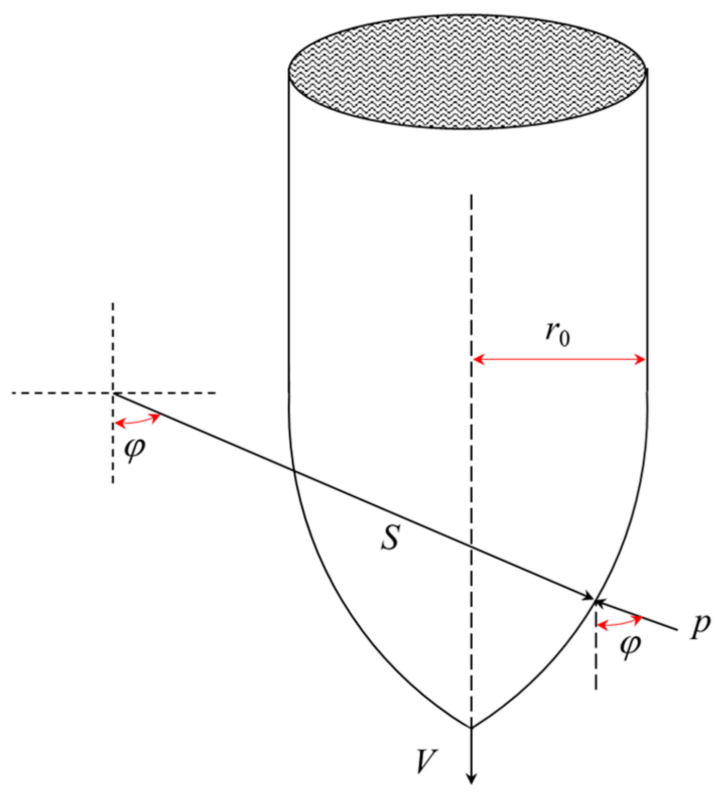
Figure 2 illustrates the stress state of an ogival-nosed projectile during its penetration of a semi-infinite concrete target in a rigid regime. In Figure 2, r0 represents the radius of the projectile, S is the radius of the arc of the ogive nose, φ is the angle between any point on the nose of the projectile and the central axis, and V is the instantaneous velocity of the projectile. Thus, the cavity expansion velocity, as defined in Equation (1), can be expressed as VR = Vcosφ.
The normal pressure exerted on the surface of the projectile nose is obtained as follows [13]:
p φ , V = a 0 + a 1 V cos φ + a 2 V cos φ 2
Chen et al. [29] demonstrated that the frictional resistance experienced by the projectile during its penetration into a concrete target is negligible. Therefore, the influence of friction was excluded from consideration in this study.
The normal pressure exerted on the surface of the ogival-nosed projectile is axially projected and subsequently integrated [18]. Consequently, the penetration resistance F of the projectile within the rigid penetration regime is determined.
F ( ψ , r 0 ) = 8 π r 0 2 ψ 2 φ 0 π 2 p cos φ sin φ sin φ 0 d φ
where ψ represents the CRH of the projectile, φ0 denotes the shape parameter of the projectile nose, and S is the radius of the arc of the projectile nose. According to the geometric relationships illustrated in Figure 2, φ0 can be calculated as φ 0 = arcsin S r 0 S .
By combining Equations (2) and (3), the expression for penetration resistance of the projectile is derived.
F = B 0 + B 1 V + B 2 V 2
where B0, B1, and B2 represent the penetration resistance coefficients derived from the integration of Equation (3).
B 0 = 8 π r 0 2 ψ 2 a 2 1 sin 2 φ 0 2 S r 0 s 1 sin φ 0
B 1 = 8 π r 0 2 ψ 2 a 1 cos 3 φ 0 3 S r 0 s π 4 φ 0 2 sin 2 φ 0 4
B 2 = 8 π r 0 2 ψ 2 a 0 cos 4 φ 0 4 S r 0 s 1 sin φ 0 1 sin 3 φ 0 3
According to Equation (4), the average axial pressure of the projectile during rigid penetration can be expressed as follows:
σ ¯ = F A 0
where A0 is the initial cross-sectional area of the projectile.
Chen et al. [30] concluded that the strength of the projectile constitutes the paramount factor influencing the transformation of the penetration regime. This study assumes that the projectile undergoes permanent deformation when the average axial pressure exceeds its dynamic strength. Consequently, the critical velocity for rigid penetration can be expressed as follows:
V r = B 1 + B 1 2 4 B 1 B 0 Y p A 0 2 B 2
where Yp is the dynamic strength of the projectile, characterized by the Hugoniot elastic limit in this study [31].

3.2. Hydrodynamic Velocity

According to the research findings of Tate [32], when the erosion rate of the projectile exceeds its plastic wave velocity, a shock wave forms at the projectile tip, and the projectile enters a hydrodynamic state. Considering that during the penetration of long-rod projectiles into semi-infinite concrete targets, since the projectile diameter is significantly smaller than the target and its length-to-diameter ratio is typically large (L/D > 5), the stress state of the projectile can be approximated as a one-dimensional stress state [10]. Therefore, the critical criterion for hydrodynamic penetration can be expressed as follows:
V h u = C H = E t p ρ p
where u is the penetration velocity, Ept is the plastic hardening modulus of the projectile, CH indicates the velocity of the plastic wave, and ρp represents the density of the projectile.
The Alekseevskii–Tate model formulates the hydrodynamic equations by incorporating the dynamic strength of the projectile Yp and the strength of the target Rt into the Bernoulli equation [32]:
ρ p V u 2 2 + Y p = ρ t u 2 2 + R t
where ρt represents the densities of the target.
Given the substantial influence of Yp and Rt on the computational outcomes of the A-T model, the determination of these parameters has remained a central research focus [6,33,34], with no consensus yet achieved. Based on the analysis of the applicability of different theoretical models for Rt by Liu et al. [13], the theoretical model proposed by Kong et al. [6] is adopted (the calculation of Yp has been elaborated in Section 3.1):
R t = a 0 + 2 3 a 1 u + 1 2 a 2 ρ t u 2
By substituting Equation (12) into Equation (11), we obtain
ρ p V u 2 2 + Y p = a 0 + 2 3 a 1 u + 1 2 a 2 u 2
Thus, the expression for the hydrodynamic velocity is derived by combining Equations (10) and (13).
V h = 4 a 1 + 16 a 1 2 36 a 2 2 a 0 2 Y p E t p 6 a 2 + E t p ρ p

3.3. Reliability Validation of Critical Velocity Models

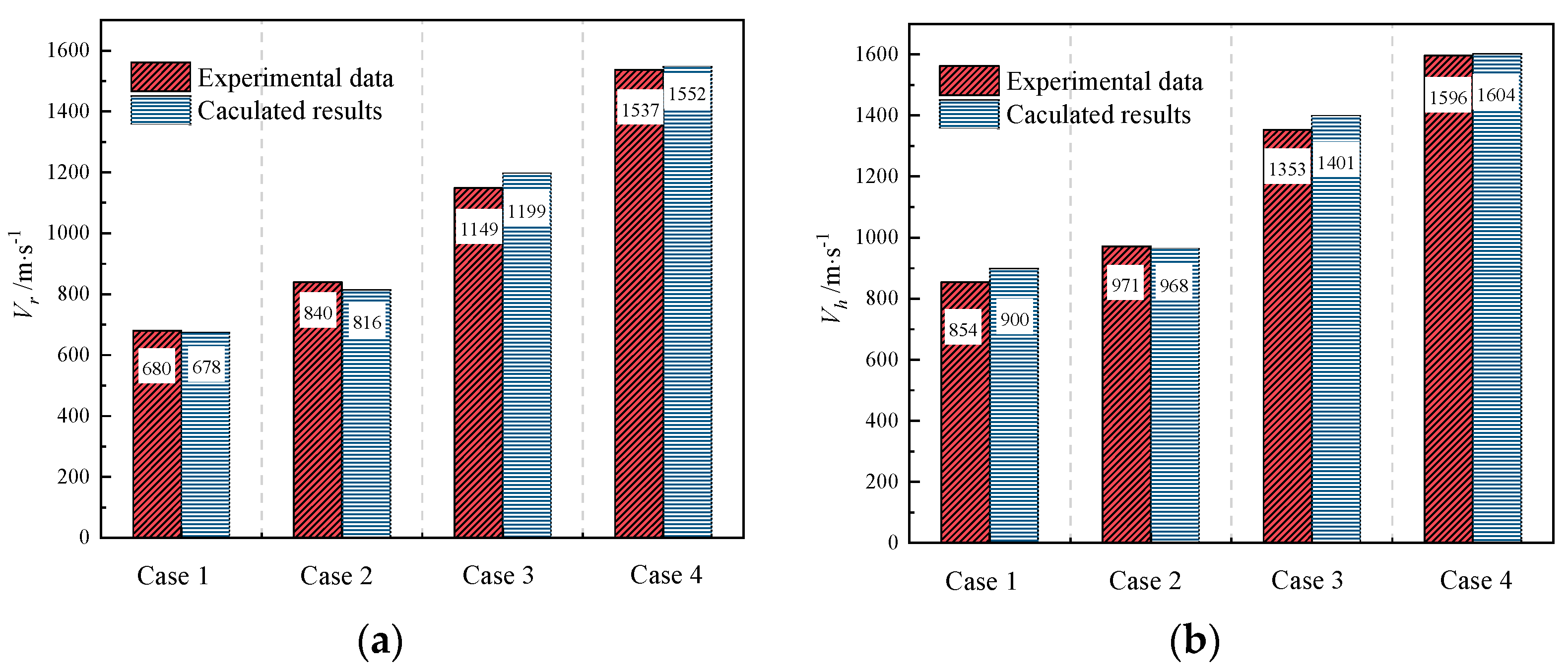
To validate the theoretical model of critical velocity established in this study, a comparative analysis of the experimental results of four series of projectile penetration into concrete targets was conducted. The experimental parameters for the projectiles and targets are listed in Table 1 and Table 2. Kong et al. [5] and Liu et al. [13] have performed experimental investigations on the penetration of flat-nosed projectiles into semi-infinite concrete targets, covering a wide range of impact velocities ranging from 500 to 1800 m/s. The unconfined compressive strengths of the concrete targets utilized in these experiments were 45.4 MPa and 50 MPa, respectively. In Case 1, the experimentally determined critical velocities for rigid penetration and hydrodynamic penetration were 682 m/s and 823 m/s, respectively. In Case 2, the critical velocities for rigid penetration and hydrodynamic penetration were observed to be 840 m/s and 971 m/s, respectively. Guo et al. [14] explored the effects of projectile diameter and material properties on the erosion of ogival-nosed projectiles. They conducted penetration experiments with ogival-nosed projectiles of diameters 12 mm and 30 mm into concrete targets with an unconfined compressive strength of 42.8 MPa, yielding rigid velocities of 1149 m/s and 1537 m/s, respectively. However, due to the constrained firing capability of the experimental apparatus, hydrodynamic velocities were not achieved. Through an analysis of the post-penetration shape characteristics of projectiles, Mu et al. [35] deduced that a key characteristic of the transition from rigid to semi-hydrodynamic penetration regime is the transformation of the nose into a hemispherical shape. Therefore, it can be simplified by considering the projectile nose as hemispherical when the impact velocity approaches the critical velocity for rigid penetration.
A comparison between the calculated critical velocities and the experimental results is depicted in Figure 3. The parameters requisite for calculation were sourced from the corresponding references. In accordance with Equations (9) and (14), the principal influencing factor for the rigid velocity is the strength of the projectile, whereas the primary determinants for the hydrodynamic velocity are the strength and plastic hardening modulus of the projectile.
As shown in Figure 3a, the calculated results for the rigid velocity are in close agreement with the experimental results, with the relative error maintained within 5%. Figure 3b presents a comparison between the calculated and experimental results for the hydrodynamic velocity. In Case 3 and Case 4, the experiments did not observe a transition from the coupled deforming/eroding regime to the hydrodynamic regime. As a result, the maximum impact velocity of the projectile under the corresponding conditions was adopted as the critical velocity for hydrodynamic penetration. As demonstrated in Figure 3b, there is a strong concordance between the calculated critical velocities for hydrodynamic penetration and the experimental data.

4. Cross-Sectional Area of the Projectile After Penetration

4.1. Fundamental Assumption

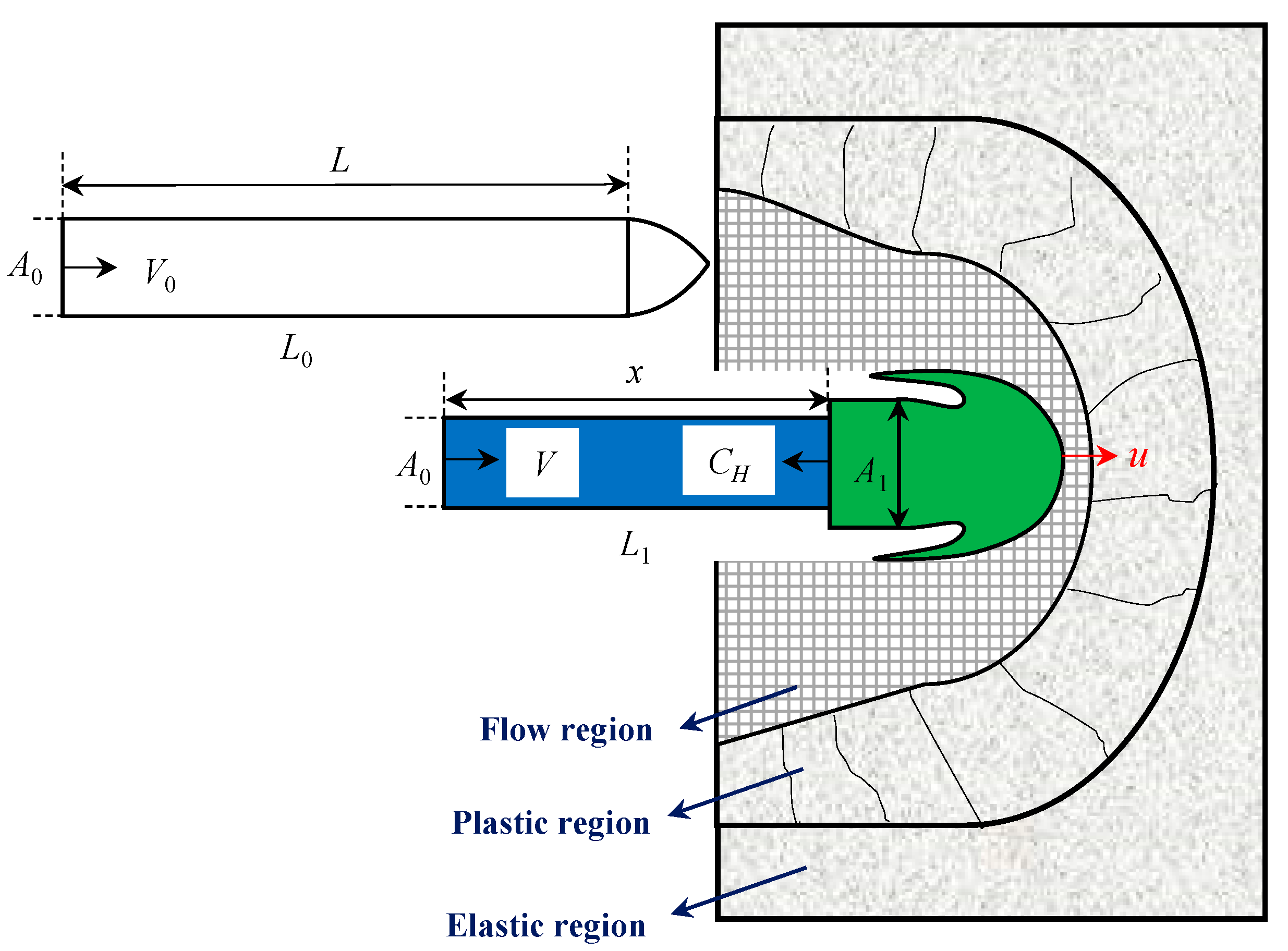
Figure 4 presents a schematic representation of a projectile penetrating a semi-infinite concrete target in a coupled deforming/eroding regime. In Figure 4, both the initial state of the projectile and its subsequent coupled deforming/eroding state are shown. L0 and L1 denote the equivalent length of the projectile before and after penetration, respectively. The equivalent length is defined as the length of a flat-nosed projectile that possesses an identical mass and cross-sectional area to the actual projectile. For a hemispherical-nosed projectile, the equivalent length L0 is determined by the equation L0 = 0.667r + L, where r represents the initial radius of the projectile nose, L represents the initial length of the projectile’s shank. A0 and A1 signify the cross-sectional area of the undeformed and deformed projectile, respectively. x denotes the length of the undeformed projectile. V0 represents the impact velocity of the projectile. CH denotes the velocity of the plastic interface, which can be approximated as the plastic wave velocity.
When the impact velocity V0 exceeds the rigid velocity Vr (i.e., when the projectile–target interfacial stress exceeds the dynamic yield strength of the projectile material), the projectile nose undergoes significant plastic deformation. Under this condition, the projectile nose can be simplified as a hemispherical shape for analysis [5,13].
After the projectile impacts the target plate, the plastic wavefront propagates along the projectile body from the nose to the tail at velocity CH, dividing the projectile into two parts: a rigid body and a plastically deforming region. In the plastic deformation region, the projectile penetrates the target at velocity u, while in the rigid body region, the projectile moves along the axial direction at velocity V. Furthermore, due to the combined effects of abrasive wear and thermal melting during high-velocity impact, the surface material of the projectile undergoes spalling, resulting in mass erosion.
In the study of the coupled deforming/eroding penetration regime, the following assumptions have been established [19]: (1) It is presumed that the projectile nose immediately adopts a hemispherical shape upon impact. (2) The influence of thermal effects on the projectile during the penetration process is disregarded. (3) The cross-sectional area of the deformed projectile is assumed to remain invariant. (4) The density of the projectile is assumed to remain constant throughout the entire penetration process. (5) The effect of projectile bending on the penetration process is not considered.

4.2. Construction of Caculated Model

In accordance with the principle of mass conservation, the total mass of a projectile is composed of the mass of the undeformed part, the mass of the deformed part, and the mass loss attributable to erosion.
L 0 A 0 = A 0 x + L 1 x A 1 + Δ M V = M 0
where ΔM(V) represents the instantaneous mass loss of the projectile, and M0 denotes the initial mass of the projectile.
Silling et al. [36] conducted a series of experiments with ogival-nosed projectiles penetrating quartzite and limestone aggregate concrete targets at velocities ranging from 450 to 1024 m·s−1. The mass erosion rate was empirically determined to exhibit a linear relationship with the impact velocity, as shown in Equation (16):
Δ M M 0 = k 1 V 0 + k 2
where k1 and k2 are linear fitting parameters.
Wu et al. [37] suggested a linear relationship between the instantaneous mass of the projectile and its corresponding instantaneous velocity. Assuming no mass loss during rigid penetration, the relationship between the mass erosion rate and the velocity of the projectile during the coupled deforming/eroding penetration process is given by
η V = Δ M V M 0 = M 0 M V M 0 = k 1 V 0 V V r < V < V h k 1 V 0 V r V < V r
where V symbolizes the instantaneous velocity, and M(V) denotes the instantaneous mass. When Vr < V0 < Vh, the projectile initially penetrates the target within a coupled deforming/eroding regime. Thereafter, when the instantaneous velocity falls below the rigid velocity (V < Vr), the projectile persists in penetrating the concrete target as a rigid body, during which its mass is presumed constant.
By combining Equations (15) and (17), the dimensionless cross-sectional area K of the projectile can be obtained.
K = A 1 A 0 = L 0 L 1 x 1 x L 0 η ( V )
By taking the plastic interface of the projectile as the reference system, we derive the following:
d V d t = Y p ρ p x
d L 1 x d t = C H + u
d x d t = V + C H
Jiao et al. [38] observed that the penetration velocity u exhibits a consistent linear relationship with the instantaneous velocity V throughout the coupled deforming/eroding penetration process. Therefore, in this study, the penetration velocity of the projectile is defined as follows:
u = a V + b
where a and b are constants. The initial boundary condition of Equation (22) is V = Vr and u = ur, and the termination boundary condition is V = Vh and u = uh, where ur and uh represent the penetration velocities corresponding to the critical states of rigid penetration and hydrodynamic penetration, respectively. The initial and terminal boundary conditions correspond to the upper and lower boundaries of the coupled deforming/eroding penetration states, respectively.
The constants in Equation (22) are determined by the aforementioned boundary conditions.
a = u h u r V h V r , b = u h u r V r V h V r
Combining Equations (19)–(23) and integrating over the velocity interval [V, V0], the lengths of the deformed and undeformed part of the projectile are expressed as follows:
x = L 0 exp ρ p Y p V 0 V V + C H d V
L 1 x = V V 0 E t p ρ p + a V + b ρ p Y p L 0 exp ρ p Y p V 0 V V + C H d V d V
By substituting Equations (24) and (25) into Equation (18), we derive the expression for the cross-sectional area that incorporates the coupled effects of deformation and erosion occurring during the semi-hydrodynamic penetration process, as presented below:
K = L 0 V r V 0 E t p ρ p + a V + b ρ p Y p L 0 exp ρ p Y p V 0 V r V + C H d V d V 1 1 exp ρ p Y p V 0 V r V + C H d V η V

4.3. Comparison of Experimental Data and Calculated Results

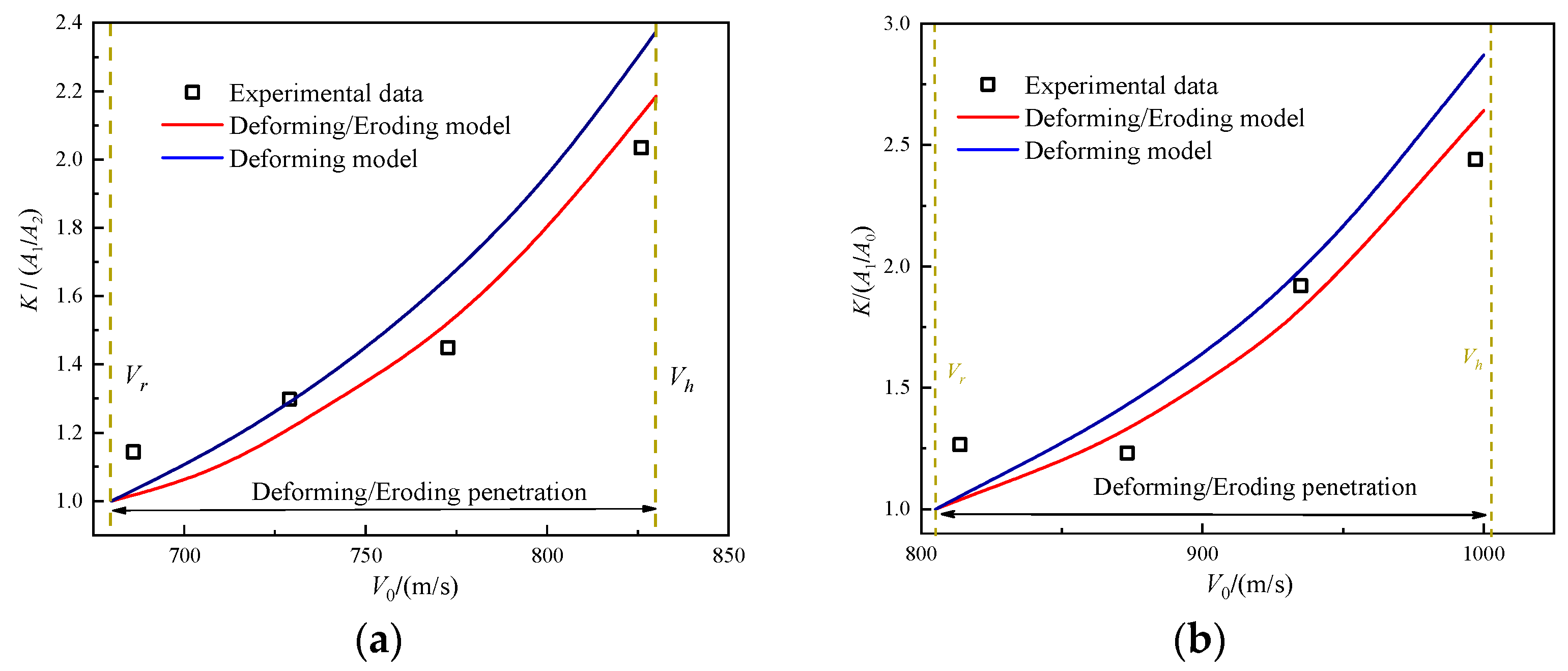
The reliability of the projectile cross-sectional area theoretical model was validated through comparison with experimental data from Liu et al. [13] and Kong [5] on residual projectile cross-sections. Two distinct cases were analyzed: Case 1 examined a 9 mm diameter medium carbon steel projectile penetrating concrete with 45.4 MPa compressive strength, while Case 2 involved a 6 mm diameter Chinese 45# steel projectile against 50 MPa concrete. Complete specifications for both projectiles and targets are detailed in Table 1 and Table 2.
Figure 5 presents the comparative analysis of model predictions and experimental results, revealing several important trends. Within the velocity range [Vr, Vh], the residual cross-sectional area shows a clear increasing trend with impact velocity, demonstrating the strong velocity-dependence of projectile deformation. When impact velocities slightly exceed the rigid velocity Vr, both the coupled deformation–erosion model and deformation-only model predictions fall below experimental measurements, primarily because neither accounts for cross-sectional area growth in the lower velocity range [0, Vr]. Importantly, the coupled model demonstrates significantly better agreement with experimental data than the deformation-only approach, particularly at higher impact velocities.
The observed behavior stems from competing physical mechanisms during penetration. While deformation acts to increase the projectile’s cross-sectional area through plastic expansion, simultaneous erosion reduces it through surface material loss. This erosion effect becomes progressively more pronounced at higher velocities, as evidenced by the widening gap between model predictions in Figure 5. Equation (17) confirms this relationship, showing the projectile mass erosion rate’s direct correlation with impact velocity. Experimental results from both cases clearly show substantially increased mass loss under high-velocity conditions, underscoring the critical importance of including erosion effects in penetration modeling.
Several factors contribute to remaining discrepancies between predictions and the experimental data of Liu et al. [13] and Kong [5]. First, the empirical formulations used for mass erosion rate may not perfectly capture the actual situation. Second, the theoretical assumption of cylindrical projectile geometry differs from actual frustum-shaped deformation patterns. Finally, the relatively small projectile sizes used in both experimental series likely introduced additional variability in the measurements. Despite these limitations, the coupled deformation–erosion model provides a more accurate representation of cross-sectional area evolution during high-velocity penetration compared to models considering deformation effects alone.

4.4. Parametric Analysis of the Cross-Sectional Area

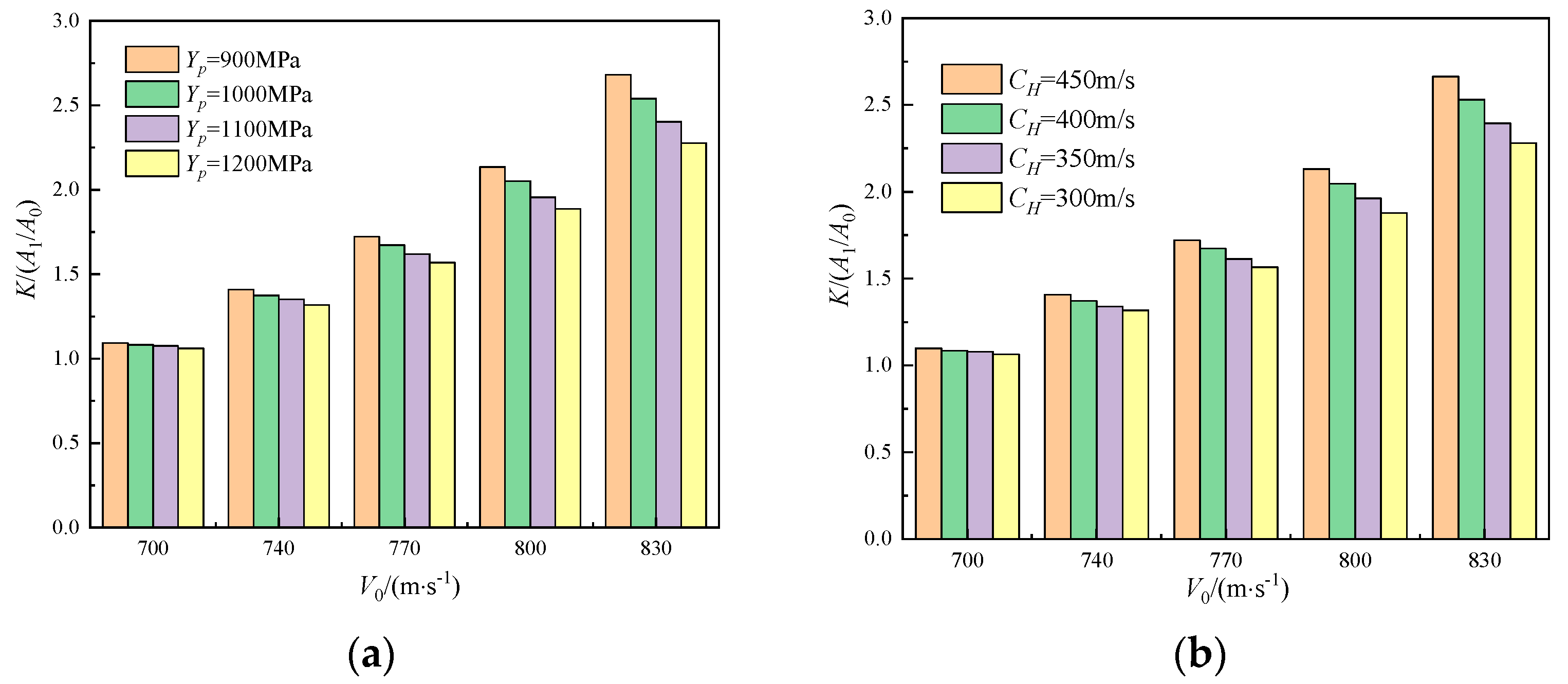
As indicated by Equation (26), the primary parameters influencing the cross-sectional area of the recovered projectile include the strength, plastic hardening modulus, density, and plastic wave velocity of the projectile. Among these factors, the density and plastic hardening modulus of the projectile influence the cross-sectional area by changing the plastic wave velocity. Consequently, this study analyzes the influence of strength Yp and plastic wave velocity CH on the cross-sectional area of the recovered projectile. The materials of the projectile and target from Case 1 were employed for the analysis, and all other parameters were maintained constant. Figure 6a,b show the relationship between the dimensionless cross-sectional area of the projectile and the impact velocity for different strengths (ranging from 900 to 1200 MPa) and different plastic wave velocities (ranging from 300 to 450 m/s), respectively. As observed in Figure 6a, the dimensionless cross-sectional area of the projectile progressively decreases with increasing projectile strength. This observation implies that under identical conditions, penetration resistance decreases as projectile strength increases. Conversely, as illustrated in Figure 6b, with constant strength, the dimensionless cross-sectional area exhibits a positive correlation with the plastic wave velocity of the projectile. The higher the plastic wave velocity, the larger the cross-sectional area of the projectile, thereby resulting in increased penetration resistance. Therefore, to enhance the penetration performance of the projectile during coupled deforming/eroding penetration, it is advisable to either increase the strength or reduce the plastic wave velocity of the projectile. The plastic wave velocity of a material is intrinsically linked to its density and plastic hardening modulus. It can be effectively reduced by increasing the density or decreasing the plastic hardening modulus.

5. Theoretical Model of DOP

5.1. Rigid Penetration

When V0 < Vr, the projectile penetrates the concrete target in a rigid regime. Consequently, the motion equation of the projectile is expressed as
F = B 0 + B 1 V + B 2 V 2 = M 0 d V d t
By integrating Equation (27) from 0 to V0 and simplifying, the DOP of rigid projectiles into the concrete targets is obtained.
P = P r i g = M 0 2 B 2 A 0 ln B 0 + B 1 V + B 2 V 2 B 1 B 2 4 B 0 B 1 2 4 B 0 B 2 B 1 + B 1 B 2 ln V 2 B 0 / B 1 2 4 B 0 B 2 B 1 V B 1 2 4 B 0 B 2 B 1 / 2 B 2 0 V 0

5.2. Coupled Deforming/Eroding Penetration

By employing the previously discussed cross-sectional area model, which accounts for the coupled deforming/eroding effect, and combining it with the equations of motion and cavity expansion theory, a comprehensive model of depth of penetration can be developed.
When Vr < V0 < Vh, the projectile initially penetrates the concrete target within a coupled deforming/eroding regime. Upon impact, the nose shape of the projectile transitions to a hemispherical form, as shown in Figure 7. According to the cavity expansion model, the normal pressure exerted on the surface of the projectile nose within this regime can be quantified as follows:
p ( θ , u ) = a 0 + a 1 u cos θ + a 2 u cos θ 2
According to Equation (29), the expression for the penetration resistance of the projectile in the coupled deformation/erosion regime is obtained:
F ( r 1 , u ) = 0 π / 2 2 π r 1 2 p sin θ cos θ d θ
where r1 is the radius after the projectile nose is deformed into a hemispherical shape, and A1 is the cross-sectional area of the projectile after deformation.
Similarly to rigid penetration, the depth of penetration Pdef can be determined based on Newton’s second law.
P d e f = ρ p L 0 K a 2 ln a 0 + 2 3 a 1 u + 1 2 a 2 u 2 24 a 0 a 1 18 a 0 a 2 4 a 1 2 arctan 6 a 0 u + 2 a 1 18 a 0 a 2 4 a 1 2 u u r
When the instantaneous velocity of the projectile decreases below the rigid velocity (V < Vr), the projectile continues to penetrate the target with a hemispherical nose in a rigid regime. The penetration resistance and depth of penetration of the residual projectile are as follows:
F r 1 , V = A 1 a 0 + 2 3 a 1 V + 1 2 a 2 V 2
P r e s , r = 0 V r V d t = M r A 1 a 2 ln a 0 + 2 3 a 1 u + 1 2 a 2 u 2 24 a 0 a 1 18 a 0 a 2 4 a 1 2 arctan 6 a 0 u + 2 a 1 18 a 0 a 2 4 a 1 2 0 V r
where Mr denotes the residual mass of the projectile.
Therefore, when the impact velocity V0 satisfies the condition Vr < V0 < Vh, the total depth of penetration is determined by summing the depths of penetration of both the coupled deforming/eroding and rigid penetration phases.
P = P r e s , r + P d e f

5.3. Comparison of Model Predictions with Experimental Data

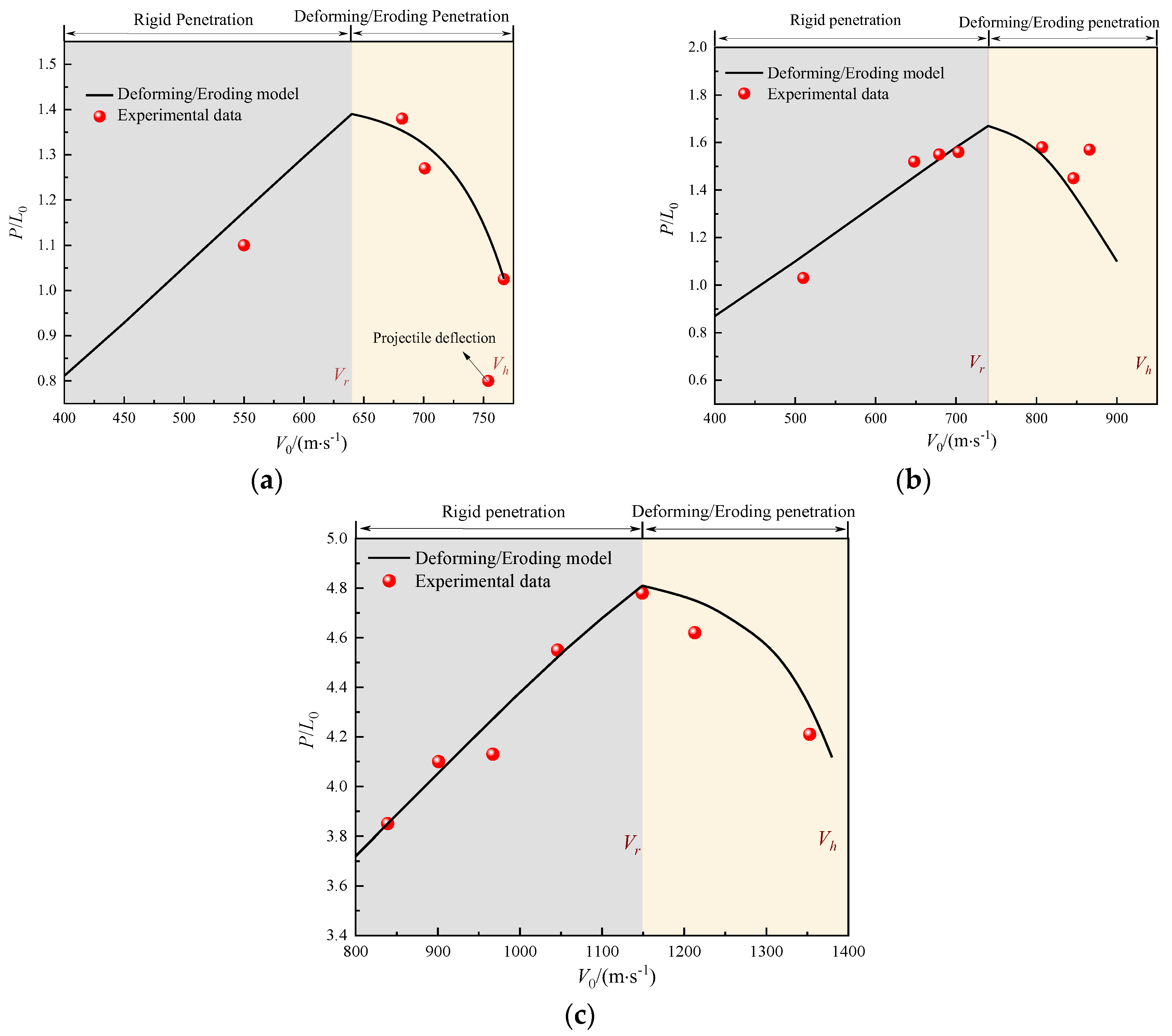
Figure 8 shows a comparison between the DOP predicted by the theoretical model proposed in this paper and the experimental data from studies [5,13]. It is evident that the predicted results are in good agreement with the experimental data. When V0 < Vr, the DOP increases linearly with the impact velocity, reaching its maximum at V0 = Vr. In the rigid penetration phase, the prediction results are marginally higher than the experimental data, likely due to minor permanent deformation and erosion of the projectile nose that occurs during actual penetration. This suggests that the projectile cannot maintain a rigid body assumed by the theoretical model, which will be addressed in a future study. When Vr < V0 < Vh, the projectile enters the coupled deforming/eroding penetration phase, wherein the DOP decreases at an accelerating rate as the velocity increases. Compared to the experimental data, the predicted results are higher. As shown in Figure 8a, the predicted DOP aligns closely with the experimental data from Case 1. During the experiment conducted at an impact velocity of 754 m/s, the projectile exited the target from the side. Consequently, the measured depth of penetration under this condition was anomalously low.
Figure 8b illustrates that the predicted DOP corresponds well with the experimental data from Case 2, except for the DOP at an impact velocity of 870 m/s. It is noteworthy that the DOPs at impact velocities of 866 m/s and 807 m/s are nearly identical, which deviates from the typical trend of decreasing DOP with increasing velocity in the coupled deforming/eroding penetration regime. This discrepancy may be attributed to the scatter of experimental data.
Figure 8c presents a comparison between the experimental data and predicted results for the terminal effects of an ogival-nosed projectile penetrating the concrete target in Case 3. The red square points in the figure represent the experimental values, while the black solid line indicates the model predictions. As shown in Figure 8c, the predicted results exhibit strong consistency with the experimental data. Figure 8a–c demonstrate that the theoretical model, which couples deforming and eroding effects, provides relatively accurate predictions for the DOP of flat-nosed and oval-nosed projectiles. This indicates that the model possesses a certain degree of accuracy and general applicability.
Figure 9 presents the photograph of the residual projectile in Case 1. At the initial stage of coupled deforming/eroding penetration with an impact velocity of V0 = 682 m/s, minimal mushrooming of the projectile is observed, accompanied by slight scratch marks on the projectile’s surface. These scratches are a consequence of the frictional interaction between the projectile’s surface and the concrete during penetration. As the impact velocity increases to V0 = 767 m/s, the frictional interaction intensifies, leading to a noticeable loss of the projectile’s original metallic luster and the observation of substantial concrete powder adhering to its surface. This adherence is attributable to the thermal softening effect on the projectile’s surface due to high-velocity friction, which facilitates the embedding of concrete particles. Concurrently, the extent of mushrooming observed on the projectile becomes considerably more pronounced. The above analysis indicates that within the coupled deformation/erosion penetration regime, the deforming and eroding effects of the projectile are significantly amplified with increasing impact velocity, leading to a progressively higher rate of decline in the depth of penetration.

6. Conclusions

This study conducted a theoretical investigation into the problem of projectiles penetrating semi-infinite concrete targets under vertical impact conditions, considering the coupled effects of deformation and erosion. The theoretical predictions were systematically compared with existing publicly available experimental data for small-scale projectiles. The main findings are summarized as follows:
(1)
The rigid velocity is defined as the critical initial impact velocity at which the projectile–target interfacial stress reaches the dynamic yield strength of the projectile, while the hydrodynamic velocity is defined as the critical impact velocity when the projectile’s erosion rate equals its internal plastic wave speed. These two critical velocities delineate the boundaries of the coupled deformation–erosion penetration regime.
(2)
The cross-sectional area evolution of projectiles is predominantly governed by material strength and plastic wave velocity. Specifically, the cross-sectional area demonstrates a negative correlation with material strength but exhibits a positive dependence on plastic wave velocity.
(3)
During the coupled deformation and erosion penetration process, the penetration depth decreases as the initial impact velocity increases. This is attributed to the increase in penetration resistance caused by the enlargement of the projectile’s cross-sectional area, as well as the significant dissipation of kinetic energy resulting from mass loss.
(4)
The theoretical framework shows good agreement with experimental data, with maximum errors of 9.5% for critical velocity prediction, 17.8% for residual projectile cross-sectional area prediction, and 24.4% for penetration depth prediction.
Given the limitations of currently available experimental data, the proposed model in this study has only been validated for small-scale projectiles under normal penetration conditions. To further verify the model’s rationality and universality, we will conduct large-scale projectile penetration tests to obtain more comprehensive experimental data. Meanwhile, structural instabilities such as bending and fragmentation that may occur during high-velocity penetration significantly affect penetration performance, yet current research on these phenomena remains inadequate. Therefore, future work will focus on investigating structural instability behavior during high-velocity projectile penetration, aiming to achieve a more comprehensive understanding of penetration mechanisms.

Author Contributions

Conceptualization, H.X., Y.L. and Z.L.; methodology, H.X., Y.L. and Z.L.; validation, H.X., Y.L. and Z.L.; formal analysis, H.X.; investigation, H.X., X.C. and X.F.; resources, X.F. and Z.L.; writing—original draft preparation, H.X., J.L. and Z.L.; writing—review and editing, H.X., J.L. and Z.L.; visualization, H.X., J.L. and Z.L.; project administration, J.L. and X.F.; funding acquisition, Z.L. All authors have read and agreed to the published version of the manuscript.

Funding

This work was supported by National Natural Science Foundation of China (NSFC) Young Scientists Fund Project (Grant No. 12202424).

Institutional Review Board Statement

Current research is limited to the field of civil engineering and protective infrastructure, which is beneficial for enhancing the safety and resilience of civilian structures and does not pose a threat to public health or national security. Authors acknowledge the dual-use potential of the research involving high-velocity impact mechanics and confirm that all necessary precautions have been taken to prevent potential misuse. As an ethical responsibility, authors strictly adhere to relevant national and international laws about Dual Use Research of Concern (DURC). Authors advocate for responsible deployment, ethical considerations, regulatory compliance, and transparent reporting to mitigate misuse risks and foster beneficial outcomes.

Data Availability Statement

The original contributions presented in the study are included in the article, further inquiries can be directed to the corresponding author.

Conflicts of Interest

The authors declare no conflict of interest.

Nomenclature

a0, a1, a2empirical coefficients related to the material properties of the target
A0cross-sectional area of the undeformed projectile
A1cross-sectional area of the deformed projectile
B0, B1, B2penetration resistance coefficients
CHplastic wave velocity
CRHcaliber-radius-head
dprojectile diameter
Etpplastic hardening modulus of the projectile
Fplastic hardening modulus of the projectile
fccompressive strength of concrete
Kcompressive strength of concrete
k1empirical mass loss coefficient
L0equivalent length of the projectile before penetration
L1equivalent length of the projectile during penetration
Llength of the projectile shank
M0initial mass of the projectile
Mrresidual mass of the projectile
M(V)instantaneous mass of the projectile
ΔMmass loss of the projectile
Prigpenetration depth of the projectile in rigid regime
Pres,rpenetration depth of the residual projectile in rigid regime
Pdefpenetration depth of the projectile in deformation and erosion regime
Ptotal penetration depth
pcavity expansion stress
r0radius of the undeformed projectile
r1radius of the deformed projectile
Rtstrength of the target
Sradius of curvature of the ogive-nosed projectile
φ0shape parameter of the projectile nose
φangle between the normal to the projectile nose surface and the penetration central axis
upenetration velocity
V0initial impact velocity
Vinstantaneous velocity during penetration
Vrrigid velocity
Vhhydrodynamic velocity
xlength of the undeformed projectile
Ypdynamic yield strength of the projectile
θangle between the surface normal of hemispherical nose and the penetration centerline
ψcaliber-radius-head
ρtdensity of the target
ρpdensity of the target
φangle between the projectile nose surface normal and the penetration centerline
η(V)instantaneous mass loss rate of the projectile
σ - average resistance acting on the projectile nose

References

  1. Ning, J.G.; Li, Z.; Ma, T.B.; Xu, X.Z. Failure behavior of projectile abrasion during high-speed penetrationinto concrete. Eng. Fail. Anal. 2020, 115, 104634. [Google Scholar] [CrossRef]
  2. Li, X.; Liu, Y.; Yan, J.B.; Shi, Z.Q.; Wang, H.F.; Xu, Y.L.; Huang, F.L. High-speed penetration of ogive-nose projectiles into thick concrete targets: Tests and a projectile nose evolution model. Def. Technol. 2024, 32, 553–571. [Google Scholar] [CrossRef]
  3. Li, Z.; Xu, X.Z. Theoretical investigation on failure behavior of ogive-nose projectile subjected to impact loading. Materials 2020, 13, 5372. [Google Scholar] [CrossRef]
  4. Gao, F.; Song, C.M.; Li, G.K.; Deng, S.X.; Wang, Z.; Liu, C.K. Experimental and analytical study on the penetration depth of mortar targets subjected to projectile impact in the hypervelocity regime. Int. J. Struct. Dyn. 2022, 22, 2250069. [Google Scholar] [CrossRef]
  5. Kong, X.Z.; Wu, H.; Fang, Q.; Zhang, W.; Xiao, Y.K. Projectile penetration into mortar targets with a broad range of striking velocities: Test and analyses. Int. J. Impact Eng. 2017, 106, 18–29. [Google Scholar] [CrossRef]
  6. Kong, X.Z.; Wu, H.; Fang, Q.; Peng, Y. Rigid and eroding projectile penetration into concrete targets based on an extended dynamic cavity expansion model. Int. J. Impact Eng. 2017, 100, 13–22. [Google Scholar] [CrossRef]
  7. Xing, H.Z.; Zhao, J.; Wu, G.; Duan, D.; Dehkhoda, S.; Lu, G.X.; Zhang, Q.B. Perforation model of thin rock slab subjected to rigid projectile impact at an intermediate velocity. Int. J. Impact Eng. 2020, 139, 103536. [Google Scholar] [CrossRef]
  8. Varnosfaderani, M.A.; Maghoul, P.; Wu, N. Modelling the penetration of subsonic rigid projectile probes into granular materials using the cavity expansion theory. Comput. Geotech. 2022, 141, 104546. [Google Scholar] [CrossRef]
  9. Alekseevskii, V. Penetration of a rod into a target at high velocity. Combust. Explos. Shock. Waves 1966, 2, 63–66. [Google Scholar] [CrossRef]
  10. Tate, A. A theory for the deceleration of long rods after impact. J. Mech. Phys. Solids 1967, 15, 387–399. [Google Scholar] [CrossRef]
  11. Lu, Y.Y.; Zhang, Q.M.; Xue, Y.J.; Guo, X.H.; Shang, C.; Liu, W.J.; Ren, S.Y.; Long, R.R. Hypervelocity penetration of concrete targets with long-rod steel projectiles: Experimental and theoretical analysis. Int. J. Impact Eng. 2021, 148, 103742. [Google Scholar] [CrossRef]
  12. Liu, C.; Zhang, X.F.; Huang, C. Critical velocity theoretical model for hemispherical long rod projectiles’ penetrating semi-infinite thick target at high velocity. J. Vib. Shock 2019, 38, 8–14. [Google Scholar]
  13. Liu, C.; Zhang, X.; Chen, H.; Wang, J.; Wei, H.; Xiong, W. Experimental and theoretical study on steel long-rod projectile penetration into concrete targets with elevated impact velocities. Int. J. Impact Eng. 2020, 138, 103482. [Google Scholar] [CrossRef]
  14. Guo, L.; He, Y.; Pan, X.C.; He, X.; Tu, J.; Qiao, L.; Pang, C.X. Experimental study on mass loss of projectile subjected to high-velocity penetration into concrete target. J. Exp. Mech. 2020, 35, 82–90. [Google Scholar]
  15. Li, G.; Song, C.M.; Qiu, Y.Y.; Wang, M.Y. Theoretical and experimental studies on the phenomenon of reduction in penetration depth of hyper-velocity projectiles into granite. Chin. J. Rock Mech. Eng. 2018, 37, 60–66. [Google Scholar]
  16. Nia, A.A.; Zolfaghari, M.; Khodarahmi, H.; Nill, M.; Gorbankhani, A.H. High velocity penetration of concrete targets with eroding long-rod projectiles; an experiment and analysis. Int. J. Prot. Struct. 2014, 5, 47–63. [Google Scholar] [CrossRef]
  17. Qian, B.W.; Zhou, G.; Li, M.R.; Yin, L.X.; Gao, P.F.; Chen, C.L.; Ma, K. Study on the critical transformation speed of rigid body of highstrength steel projectile penetrating concrete target at high speed. Explo. Shock Waves 2024, 44, 147–157. [Google Scholar]
  18. Lu, Z.C.; Zhang, Y.D.; Wen, H.M.; Zhou, G.; Li, M.R.; Qian, B.W. Theoretical study on the penetration of long rods into semiinfinite concrete target. Mod. Appl. Phys. 2018, 9, 13–24. [Google Scholar]
  19. Zhang, Y.D.; Lu, Z.C.; Wen, H.M. On the penetration of semi-infinite concrete targets by ogival-nosed projectiles at different velocities. Int. J. Impact Eng. 2019, 129, 128–140. [Google Scholar] [CrossRef]
  20. Wen, H.M.; Lan, B. Analytical models for the penetration of semi-infinite targets by rigid, deformable and erosive long rods. Acta Mech. Sin. 2010, 26, 573–583. [Google Scholar] [CrossRef]
  21. Chen, X.W.; He, L.L.; Yang, S.Q. Modeling on mass abrasion of kinetic energy penetrator. Eur. J. Mech-A/Solids 2010, 29, 7–17. [Google Scholar] [CrossRef]
  22. He, L.L.; Chen, X.W.; He, X. Parametric study on mass loss of penetrators. Acta Mech. Sin. 2010, 26, 585–597. [Google Scholar] [CrossRef]
  23. Zhao, J.; Chen, X.W.; Jin, F.N.; Xu, Y. Depth of penetration of high-speed penetrator with including the effect of mass abrasion. Int. J. Impact Eng. 2010, 37, 971–979. [Google Scholar] [CrossRef]
  24. Zhao, J.; Chen, X.W.; Jin, F.N.; Xu, Y. Analysis on the bending of a projectile induced by asymmetrical mass abrasion. Int. J. Impact Eng. 2012, 39, 16–27. [Google Scholar] [CrossRef]
  25. Hao, O.; Chen, X.W. Modeling on mass loss and nose blunting of high-speed penetrator into concrete target. Int. J. Prot. Struct. 2019, 10, 3–25. [Google Scholar] [CrossRef]
  26. Guo, L.; He, Y.; Zhang, X.F.; He, Y.; Deng, J.; Guan, Z. Thermal-mechanical analysis on the mass loss of high-speed projectiles penetrating concrete targets. Eur. J. Mech.-A/Solids 2017, 65, 159–177. [Google Scholar] [CrossRef]
  27. Yao, Z.; Huang, F.L.; Li, J. Research on mass loss and nose shape evolution of kinetic energy projectiles penetrating concrete at high velocity. Acta Mech. Sin. 2024, 40, 423410. [Google Scholar] [CrossRef]
  28. Deng, Y.J.; Song, W.J.; Chen, X.W. Spherical cavity-expansion model for penetration of reinforced-concrete targets. Acta Mech. Sin. 2019, 35, 535–551. [Google Scholar] [CrossRef]
  29. Chen, X.W.; Li, Q.M. Deep penetration of a non-deformable projectile with different geometrical characteristics. Int. J. Impact Eng. 2002, 27, 619–637. [Google Scholar] [CrossRef]
  30. Chen, X.W.; Li, Q.M. Transition from nondeformable projectile penetration to semihydrodynamic penetration. J. Eng. Mech. 2004, 130, 123–127. [Google Scholar] [CrossRef]
  31. Lan, B.; Wen, H.M. Alekseevskii-Tate revisited: An extension to the modified hydrodynamic theory of long rod penetration. Sci. China Technol. Sci. 2010, 53, 1364–1373. [Google Scholar] [CrossRef]
  32. Tate, A. A possible explanation for the hydrodynamic transition in high speed impact. Int. J. Mech. Sci. 1977, 19, 121–123. [Google Scholar] [CrossRef]
  33. Zhang, L.S.; Huang, F.L. Model for long-rod penetration into semi-infinite targets. J. Beijing Inst. Technol. 2004, 13, 285–289. [Google Scholar]
  34. Tate, A. Long rod penetration models—Part II. Extensions to the hydrodynamic theory of penetration. Int. J. Mech. Sci. 1986, 28, 599–612. [Google Scholar] [CrossRef]
  35. Mu, Z.C.; Zhang, W. An investigation on mass loss of ogival projectiles penetrating concrete targets. Int. J. Impact Eng. 2011, 38, 770–778. [Google Scholar] [CrossRef]
  36. Silling, S.; Forrestal, M. Mass loss from abrasion on ogive-nose steel projectiles that penetrate concrete targets. Int. J. Impact Eng. 2007, 34, 1814–1820. [Google Scholar] [CrossRef]
  37. Wu, H.J.; Huang, F.L.; Wang, Y.N.; Duan, Z.P.; Shan, Y. Mass loss and nose shape change on ogive-nose steel projectiles during concrete penetration. Int. J. Nonlinear Sci. Numer. Simul. 2012, 13, 273–280. [Google Scholar] [CrossRef]
  38. Jiao, W.J.; Chen, X.W. Approximate solutions of the Alekseevskii–Tate model of long-rod penetration. Acta Mech. Sin. 2018, 34, 334–348. [Google Scholar] [CrossRef]
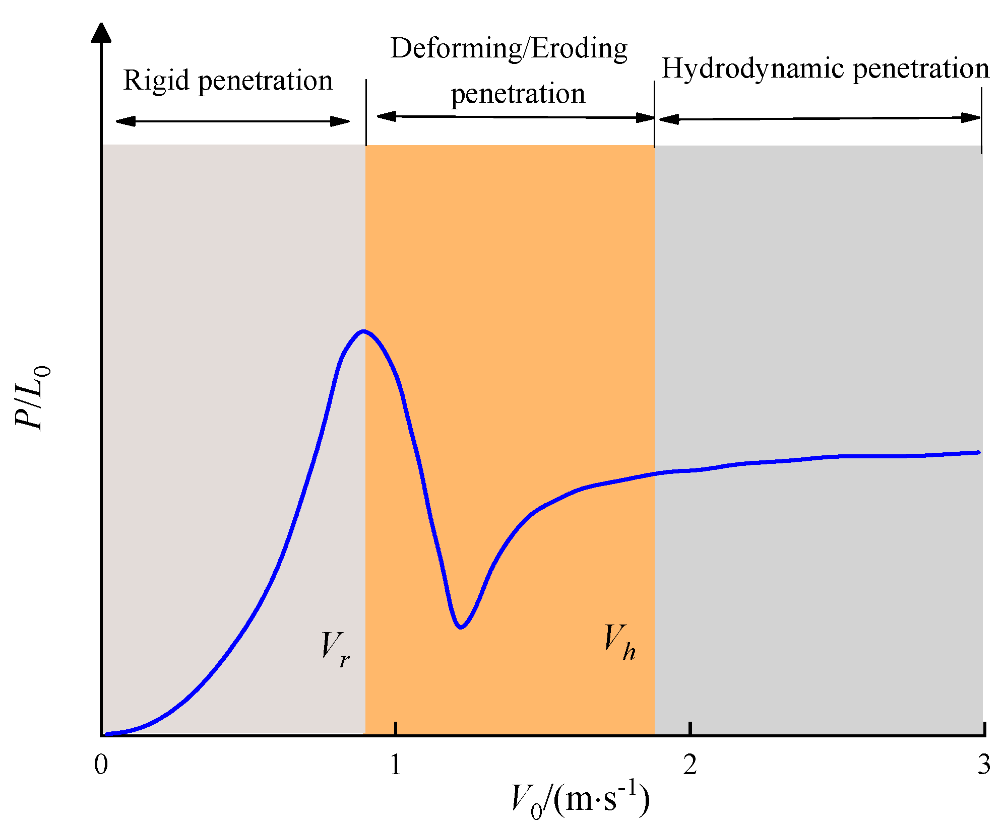
Figure 1. Schematic diagram of penetration regimes at different impact velocities [19].
Buildings 15 01607 g001
Figure 2. Schematic diagram of the stress state of an ogival-nosed projectile penetrating a semi-infinite concrete target in a rigid regime.
Buildings 15 01607 g002
Figure 3. Comparison of model calculations and experimental results for critical velocity: (a) the critical velocity for rigid penetration; (b) the critical velocity for hydrodynamic penetration.
Buildings 15 01607 g003
Figure 4. Sketch of coupled deforming/eroding penetration regime.
Buildings 15 01607 g004
Figure 5. Comparison of model calculations and experimental results for the non-dimensional cross-sectional area: (a) Case 1 (Experimental data were obtained from Ref. [13]); (b) Case 2 (Experimental data were obtained from Ref. [5]).
Buildings 15 01607 g005
Figure 6. The non-dimensional cross-sectional area with different projectile strengths and plastic wave velocities: (a) calculated results for different projectile strengths; (b) calculated results for different plastic wave velocities.
Buildings 15 01607 g006
Figure 7. Stress state of projectile during the coupled deforming/eroding penetration process.
Buildings 15 01607 g007
Figure 8. Comparison of model calculations and experimental results for the non-dimensional DOP: (a) Case 1 (Experimental data were obtained from Ref. [13]); (b) Case 2 (Experimental data were obtained from Ref. [5]); (c) Case 3 (Experimental data were obtained from Ref. [14]).
Buildings 15 01607 g008
Figure 9. Photographs of the recovered projectile [13].
Buildings 15 01607 g009
Table 1. Projectile parameters.
TypeProjectile
ρp/(kg·m−3)M0/gCRHd/mmL0/mmL/DEpt/MPaYp/GPa
Case 1 [13]780038.809808.887000.9
Case 2 [5]78006.58063057001.1
Case 3 [14]780068.531296812001.45
Case 4 [14]7800322.533090314001.95
Note: ρp denotes the projectile density, M0 denotes the projectile mass, CRH indicates the projectile head curvature ratio, d indicates the projectile diameter, L0 is the projectile length, and L/D represents the projectile length-to-diameter ratio.
Table 2. Target parameters.
TypeTarget
ρt/(kg·m−3)fc/MPaa0/(108 Pa)a1/(106 kg·m−2·s−1)a2/(103 kg·m−3)
Case 1 [13]240045.44.071.561.48
Case 2 [5]2400504.481.631.48
Case 3 [14]220042.83.831.451.36
Case 4 [14]220042.83.831.451.36
Note: ρt denotes the target density, fc represents the compressive strength of concrete, and a0, a1, a2 are resistance coefficients related to the target material properties from study [6].
Disclaimer/Publisher’s Note: The statements, opinions and data contained in all publications are solely those of the individual author(s) and contributor(s) and not of MDPI and/or the editor(s). MDPI and/or the editor(s) disclaim responsibility for any injury to people or property resulting from any ideas, methods, instructions or products referred to in the content.