
Post-Fire Mechanical Properties of Half-Grouted Sleeve Connectors with Grouting Defects


Abstract
1. Introduction
- (1)
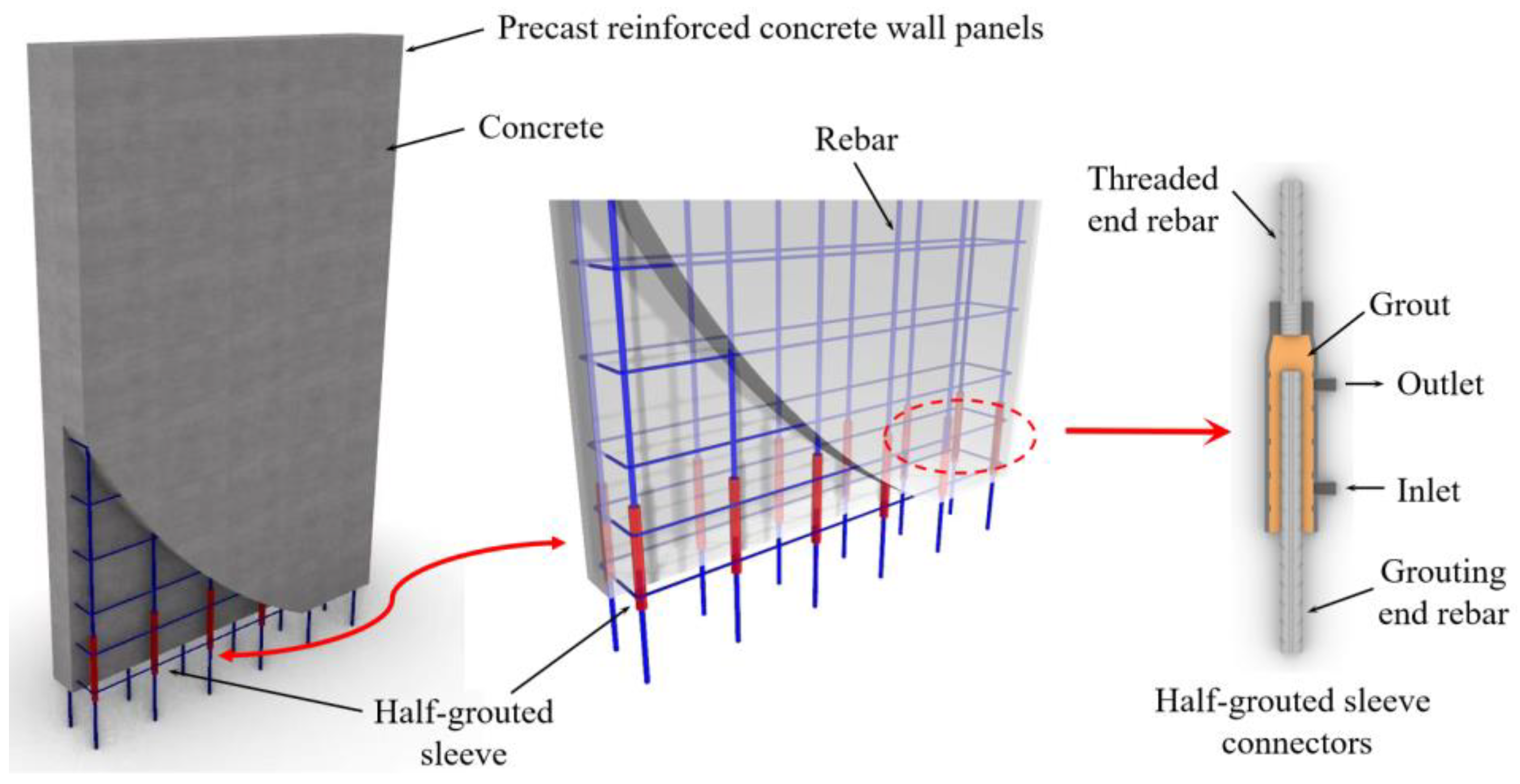
- Sleeve factors: the material from which the sleeve is made can significantly impact its properties. Different materials have varying strength, durability, and resistance to corrosion, which can affect the overall structural integrity of the sleeve. The structural design of the sleeve, including its shape and configuration, can affect its load-bearing capacity and resistance to deformation. The reduction of inner rib spacing can improve the bearing capacity of the sleeve up to a certain extent. However, there is a limit beyond which further reduction in spacing may not provide significant benefits. The thickness of the sleeve walls can influence its strength and stiffness. Thicker sleeves generally have higher load-bearing capacity. The sleeve inner diameter of the sleeve determines the size and type of rebars that can be accommodated. It can also affect the flow and compaction of grout within the sleeve [9].
- (2)
- Rebar factors: the diameter of the rebars used in the half-grouted sleeve can impact its dynamic loading performance and ductility. Larger diameter bars generally enhance the ductility of the grouted sleeve [10,11]. The anchorage length of rebar embedded within the sleeve affects its bonding strength with the grout. Longer anchorage lengths generally contribute to higher ultimate bearing capacity. The displacement or offset of rebar within the sleeve can influence the properties of the half-grouted sleeve [12]. Huang et al. [10] investigated that rebar offsets up to 6 mm may have negligible effects on the sleeve’s properties.
- (3)
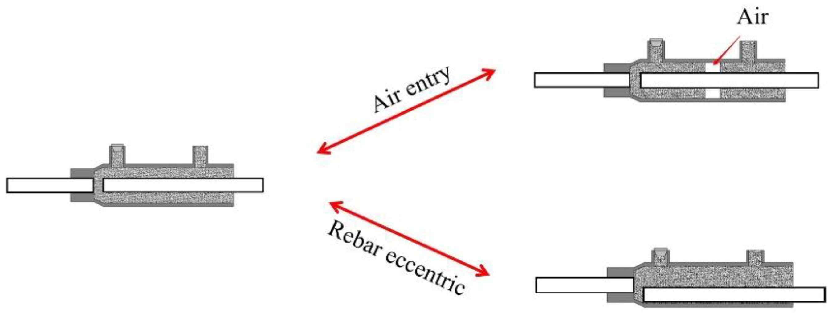
- Grout factors: the strength of the grout used to fill the half-grouted sleeve is an important factor for optimizing its properties. Higher grout strength contributes to increased load-bearing capacity and overall performance. The level of compaction achieved during the grouting process affects the failure mode of the grouted sleeve under loading [13]. Proper compaction helps ensure better load transfer and overall stability. The water-binder ratio in the grout is crucial, especially for large-diameter sleeve connections. Strict control of the water-binder ratio is necessary to maintain the desired strength and performance of the half-grouted sleeve [14]. These factors demonstrate the complexity of designing and optimizing the properties of half-grouted sleeves in prefabricated buildings. Studying and understanding these factors can help ensure the safe and efficient use of such construction methods.
2. Materials and Methods
2.1. Specimens Design
2.2. Materials
2.3. Fabrication Procedure
2.4. Test Setup and Loading Pattern
2.4.1. Heating Scheme
2.4.2. Loading Scheme
3. Results Analysis and Discussion
3.1. Failure Modes
3.2. Bearing Capacity Analysis
3.2.1. Analysis at 25 °C~200 °C
3.2.2. Analysis at 300 °C~400 °C
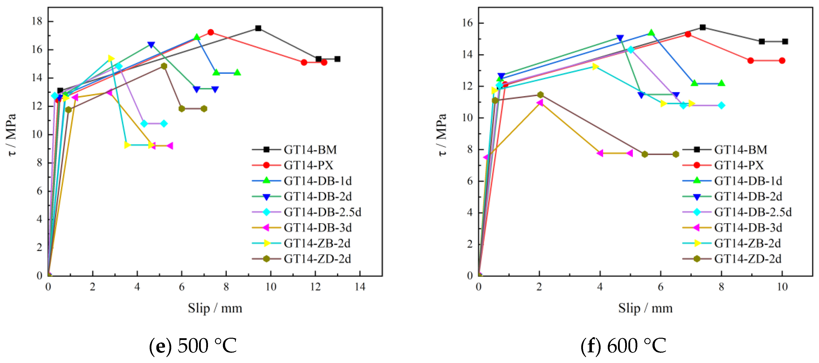
3.2.3. Analysis at 500 °C~600 °C
3.3. Grey Correlation Analysis of Ultimate Strength
3.4. Bond Stress-Slip Constitutive Model
3.5. Real Situation Fitting and Performance Improvement
4. Conclusions
- (1)
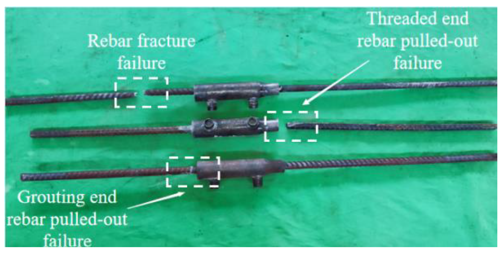
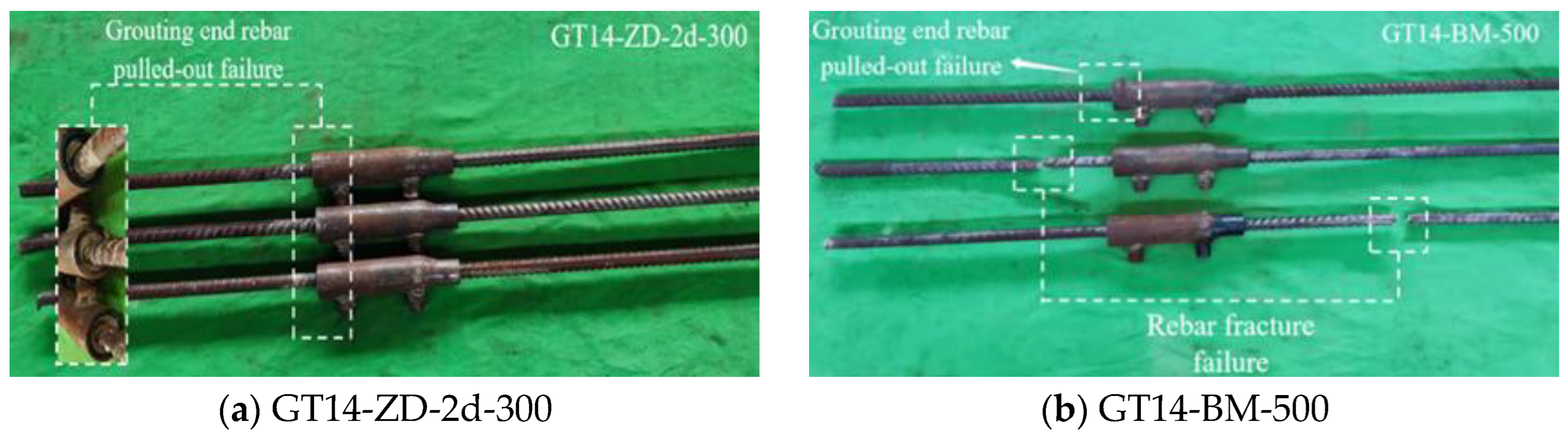
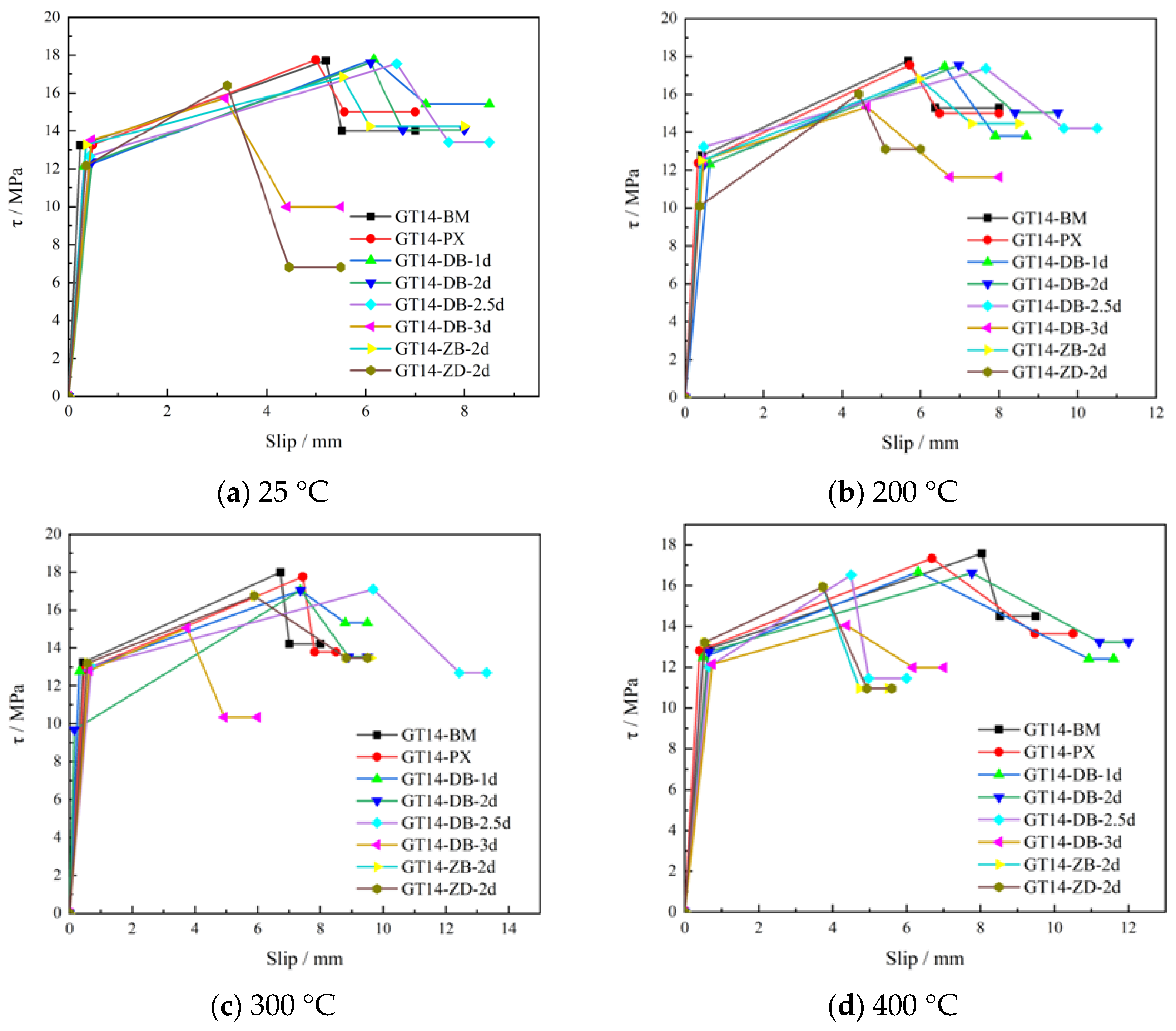
- The primary failure modes observed in the half-grouted sleeve specimens are rebar fracture failure and rebar pull-out failure. Upon reaching temperatures of 500 °C for non-defective specimens or exceeding 400 °C for defective specimens, a significant deterioration in the tensile properties of the half-grouted sleeve is evident, leading to a universal occurrence of rebar pull-out failure across all specimens.
- (2)
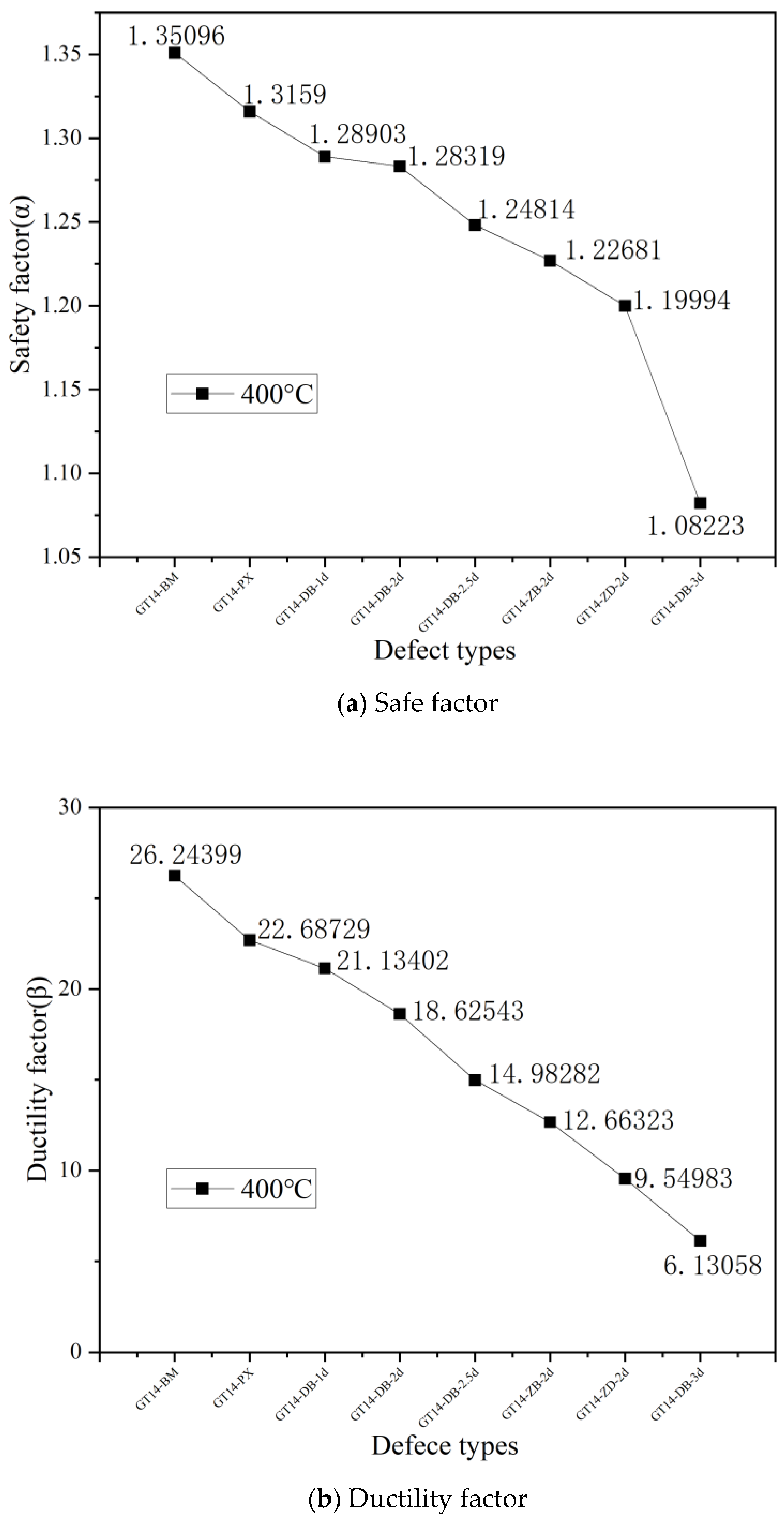
- When the temperature reaches 400 °C, all the defect groups with reduced anchorage length fail. Different types of defects have different effects on mechanical properties of half-grouted sleeve specimens. The 3d defect at the end has the greatest influence on the tensile properties of the half-grouted sleeve connection. When the end defect length reaches 35 mm, because the defect length is too large, the anchorage length decreases, and the cementation force between the reinforcement and the grouting material is far less than the ultimate tensile strength of the reinforcement, the specimen is not reliable at normal temperature. The influence degree of different defects is greater than that of temperature.
- (3)
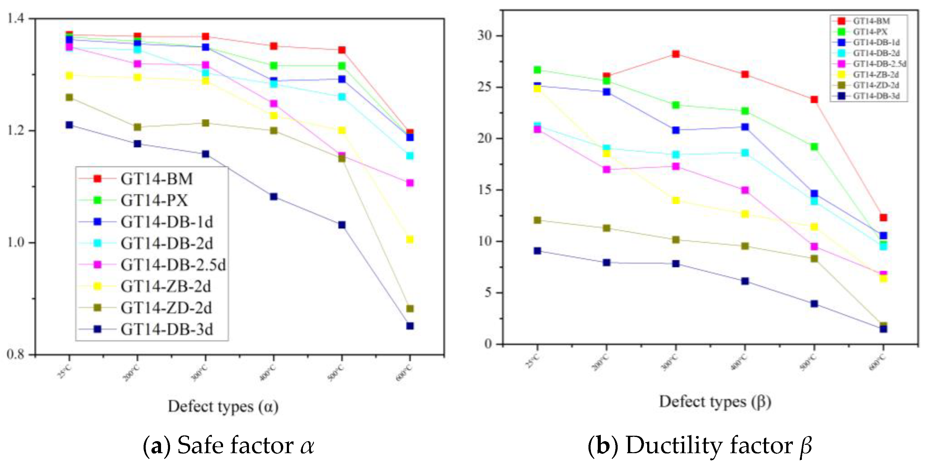
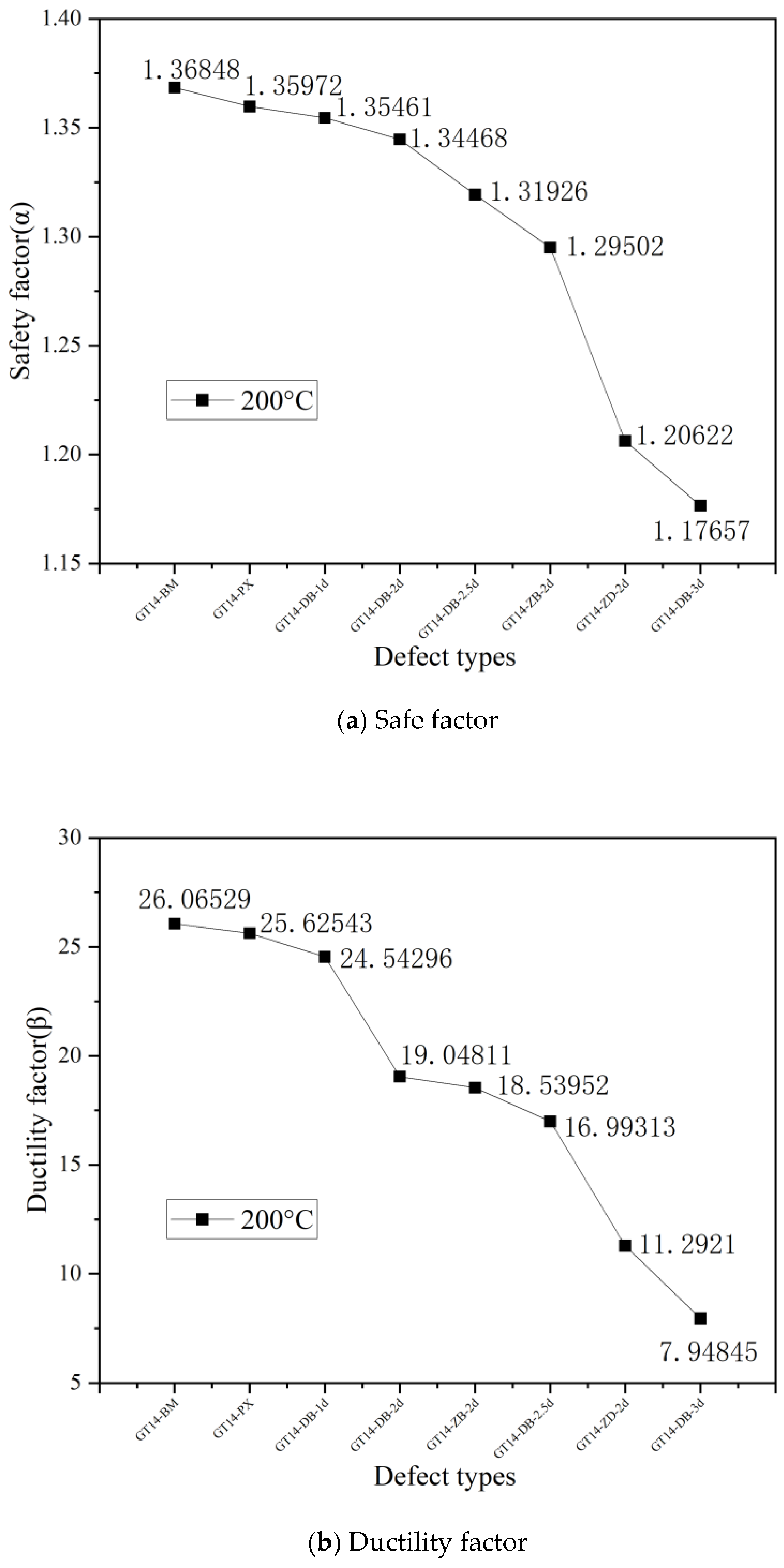
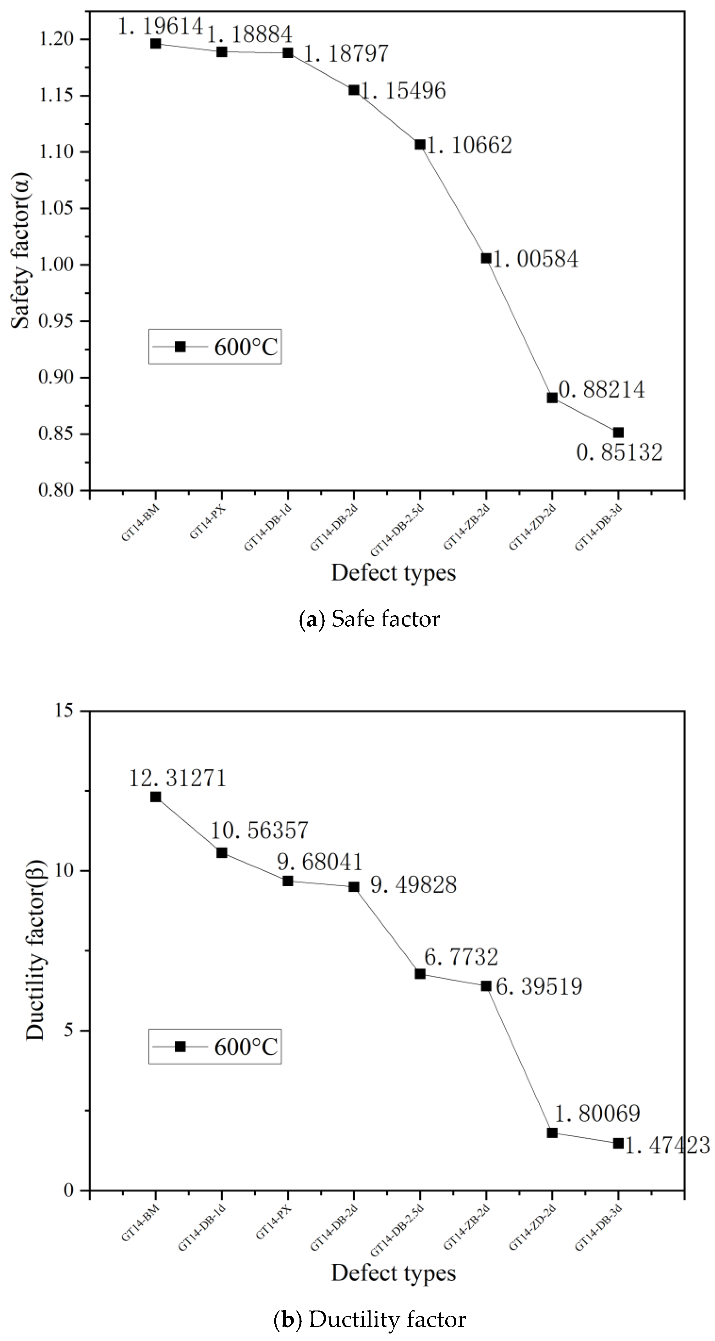
- The ultimate tensile force, yield tensile force, safety factor and ductility factor of half-grouted sleeves with or without grouting defects decrease with increases in temperature. The rate of increase or decrease of these parameters varies depending on the type of defect. High temperatures and construction defect have important influence on the reliability of half-grouted sleeve connections. The defects have greater influence on it through the grey correlation analysis. The practical engineering significance provided in this experiment is as follows: considering that defects cannot be avoided during the production and construction process, it is necessary to increase the thickness of the protective layer of the wall while reducing defects to improve fire-resistance performance, so as to control the indoor temperature within 400 degrees Celsius as much as possible after a fire occurs.
- (4)
- The use of advanced grouting materials or concrete can effectively improve the anti-cracking performance of time. When the conclusion is extended to full-size specimens, considering the size effect, the bearing capacity of specimens can be improved by increasing the section size of columns or using cement-based grouting materials instead of concrete.
- (5)
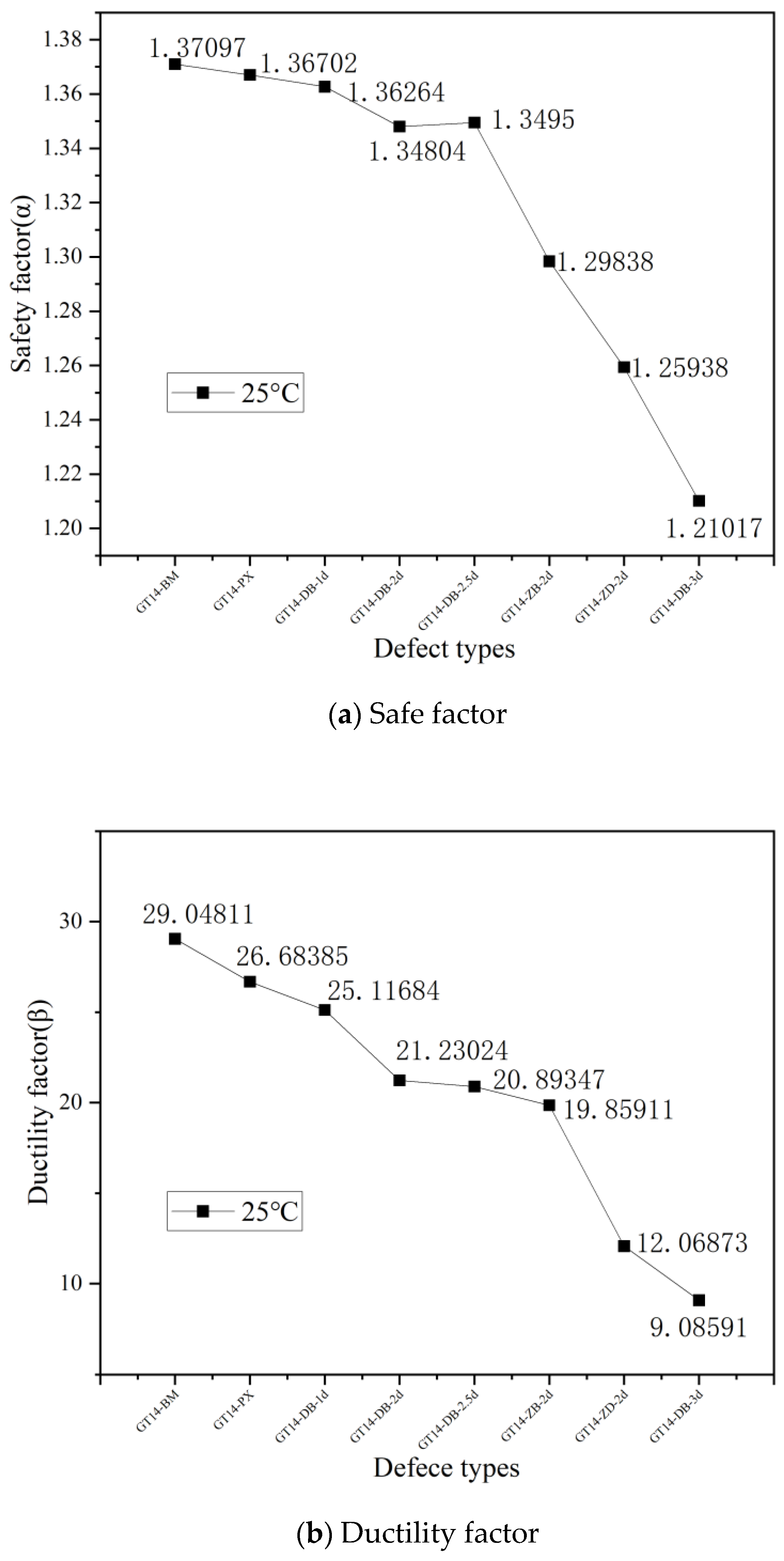
- For half-grouted sleeve connectors with the same total defect lengths, discrete defects result in lower bearing capacity compared to concentrate defects, and when defects are farther away from the sleeve end, the bearing capacity is lower. GT14-DB-2d has the best performance, followed by GT14-ZB-2d, and GT14-ZD-2d has the worst properties.
- (6)
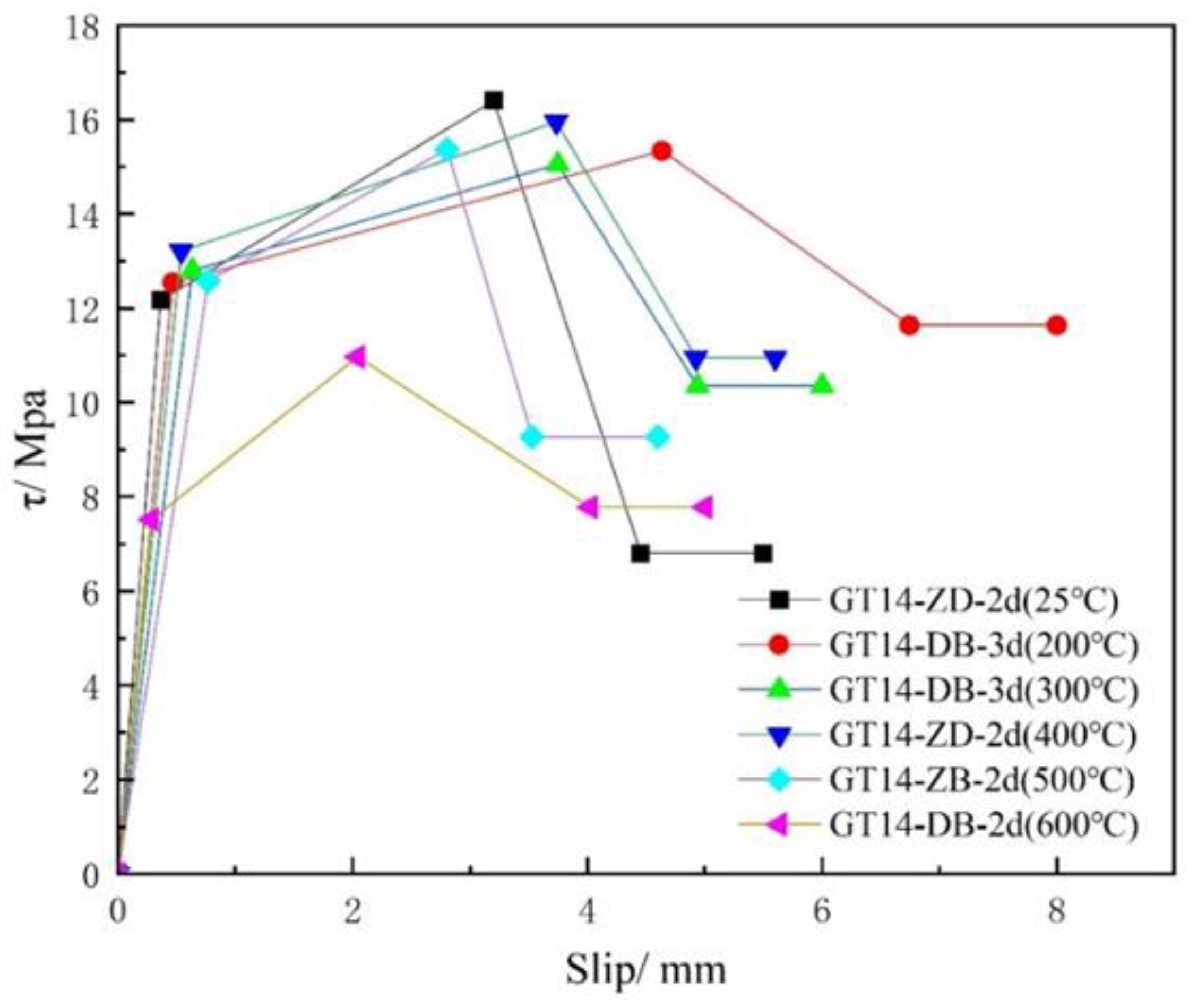
- Taking 400 °C as the critical point, high temperature has a significant impact on the stress of the half-grouted sleeve component after fire, so it is necessary to strengthen and improve the high temperature damage resistance of the half-grouted sleeve. By comparing the ultimate strength of the half-grouted sleeve with different thicknesses of the protective layer at different temperatures, it can be found that the ultimate strength and displacement of the specimen with the protective layer increase significantly, indicating that the appropriate increase in the thickness of the protective layer can effectively improve the ultimate strength of the half-grouted sleeve. In addition, the increase in anchorage length can also effectively improve the fire resistance of the connecting part.
Author Contributions
Funding
Data Availability Statement
Conflicts of Interest
References
- Che, W.P.; Chen, J.W.; Liu, Z.Y.; Tian, W.L. Mechanical properties of cast half-grouted sleeve splice with rebar bonding defects. Adv. Struct. Eng. 2022, 25, 2870–2884. [Google Scholar] [CrossRef]
- Zhao, C.F.; Zhang, Z.D.; Wang, J.F.; Wang, B. Numerical and theoretical analysis on the mechanical properties of improved CP-GFRP splice sleeve. Thin-Walled Struct. 2019, 137, 487–501. [Google Scholar] [CrossRef]
- Xu, L.; Pan, J.L.; Cai, J.M. Seismic performance of precast RC and RC/ECC composite columns with grouted sleeve connections. Eng. Struct. 2019, 188, 104–110. [Google Scholar] [CrossRef]
- Han, Q.; Li, X.P.; Xu, K.; Lu, Y.Q.; Du, X.L.; Wang, Z.Q. Shear strength and cracking mechanism of precast bridge columns with grouted sleeve connections. Eng. Struct. 2021, 230, 111616. [Google Scholar] [CrossRef]
- Liu, H.T.; Chen, J.N.; Xu, C.S.; Du, X.L. Seismic performance of precast column connected with grouted sleeve connectors. J. Build. Eng. 2020, 31, 101410. [Google Scholar] [CrossRef]
- Tang, H.S.; Xie, Y.J.; Zhao, T.T.; Xue, S.T. Identification of Grout Sleeve Joint Defect in Prefabricated Structures Using Deep Learning. Front. Mater. 2020, 7, 298. [Google Scholar] [CrossRef]
- Liu, Q.Z.; Li, J.Z.; Li, M.F.; Wu, X.K.; Li, Y.C.; Zhang, L. Bond performance prediction model of defective grout in post-fire sleeve connections under cyclic loading. Constr. Build. Mater. 2023, 400, 132442. [Google Scholar] [CrossRef]
- Li, Y.B.; Cheng, L.; Lei, W.Y.; Su, Y.; Huang, T.; Zhu, Y.X.; Mei, C.; He, X.Y. Microstructures and mechanical property of post-fire grouting sleeve connections considering concrete cover. Constr. Build. Mater. 2023, 403, 132578. [Google Scholar] [CrossRef]
- Gao, Q.; Zhao, W.J. Experimental study on factors influencing the connection performance of grouted welded sleeves under uniaxial tensile loads. J. Build. Eng. 2021, 43, 103033. [Google Scholar] [CrossRef]
- Huang, Y.; Zhu, Z.G.; Naito, C.J.; Yi, W.J. Tensile behavior of half grouted sleeve connections: Experimental study and analytical modeling. Constr. Build. Mater. 2017, 152, 96–104. [Google Scholar]
- Yu, Q.; JQ, S.; WH, Y. Experimental study on bond behavior between ribbed steel bars and sleeve constrained grouting material. J. Harbin Inst. Technol. 2018, 50, 98–106. [Google Scholar]
- Liu, C.; Pan, L.F.; Liu, H.; Tong, H.W.; Yang, Y.B.; Chen, W. Experimental and numerical investigation on mechanical properties of grouted-sleeve splices. Constr. Build. Mater. 2020, 260, 120441. [Google Scholar] [CrossRef]
- Guo, H.; Zhang, J.; Wang, C. Experimental study on influence of connection defects on joint strength of half-grouted sleeve splicing of rebar. Adv. Civ. Eng. 2020, 2020, 5389861. [Google Scholar] [CrossRef]
- Chen, J.W.; Wang, Z.W.; Liu, Z.Y.; Ju, S.L. Experimental investigation of mechanical behaviour of rebar in steel half-grouted sleeve connections with defects in water/binder ratio. Structures 2020, 26, 487–500. [Google Scholar] [CrossRef]
- Zhang, X.; Zhao, Y.H.; Guo, Y.F.; Li, Z.Y. Equivalent stress-strain model of half grouted sleeve connection under monotonic and repeated loads: Experiment and preliminary application. Eng. Struct. 2022, 260, 114247. [Google Scholar] [CrossRef]
- Zheng, G.Y.; Kuang, Z.P.; Xiao, J.Z.; Pan, Z.F. Mechanical performance for defective and repaired grouted sleeve connections under uniaxial and cyclic loadings. Constr. Build. Mater. 2020, 233, 117233. [Google Scholar] [CrossRef]
- Xu, F.; Wang, K.; Wang, S.G.; Li, W.W.; Liu, W.Q.; Du, D.S. Experimental bond behavior of deformed rebars in half-grouted sleeve connections with insufficient grouting defect. Constr. Build. Mater. 2018, 185, 264–274. [Google Scholar] [CrossRef]
- Kahama, E.K.; Xie, F.Z.; Anglaaere, D.L.M. Numerical study on the influence of defects in grouting on the mechanical properties of a full grouted sleeve connector. J. Adhes. 2022, 98, 2550–2581. [Google Scholar] [CrossRef]
- Zheng, Q.L.; Wang, N.; Tao, L.; Xu, W.J. Experimental study on effects of grout defects on the connection behaviors of grout sleeve splicing for reinforcing bars. Build. Sci. 2017, 33, 61–68. [Google Scholar]
- Xie, L.; Wang, X.; Yang, C.; Jiang, Y.; Liu, Q.; Miao, Q.; Chen, X. Development and validation of a defect detection and repair method for half grouted sleeve connection. Case Stud. Constr. Mater. 2022, 17, e01205. [Google Scholar] [CrossRef]
- Chen, H.B.; Zhou, J.C. Experimental study on mechanical properties of sleeve grouting material after fire. J. Saf. Sci. Technol. 2022, 18, 145–151. [Google Scholar]
- Zhang, W.X.; Deng, X.; Zhang, J.Y.; Yi, W.J. Tensile behavior of half grouted sleeve connection at elevated temperatures. Constr. Build. Mater. 2018, 176, 259–270. [Google Scholar] [CrossRef]
- Zhu, J.N.; Ma, J.F.; Guo, D.D.; Wu, Y.P.; Ma, J.J. Study on tensile properties of semi grouted sleeve connectors after high temperature. Constr. Build. Mater. 2021, 302, 124088. [Google Scholar] [CrossRef]
- Zhang, W.X.; Lv, W.L.; Zhang, J.Y.; He, C.; Deng, X.; Yi, W.J. Post-fire tensile properties of half-grouted sleeve connection under different cooling paths. Fire Saf. J. 2019, 109, 102848. [Google Scholar] [CrossRef]
- Wang, T.; Xu, H.M.; Yu, M.; Xu, L.H.; Ye, J.Q. Experimental investigation on the failure modes of grouted sleeve connections under thermal and mechanical loads. Eng. Fail. Anal. 2020, 109, 104246. [Google Scholar] [CrossRef]
- Wang, T.; Yu, M.; Li, X.Y.; Yan, Z.G.; Saafi, M.; Ye, J.Q. Experimental investigation on the post-fire cyclic behavior of grouted sleeve connections. Constr. Build. Mater. 2021, 279, 122394. [Google Scholar] [CrossRef]
- Xiao, J.Z.; Liu, L.L.; Ding, T.; Xie, Q.H. Experimental study on mechanical behavior of thermally damaged grouted sleeve splice under cyclic loading. Struct. Concr. 2020, 21, 2494–2514. [Google Scholar] [CrossRef]
- Zhang, W.X.; He, C.; Zhang, J.Y.; Yi, W.J.; Deng, X. Mechanical behavior of post-fire half-grouted sleeve connection covered by concrete. Constr. Build. Mater. 2019, 201, 218–231. [Google Scholar] [CrossRef]
- JG/T408-2019; Cementitious Grout for Sleeve of Rebar Splicing. Architecture & Building Press: Beijing, China, 2019.
- JGJ 107-2016; Technical Specification for Mechanical Splicing of Steel Reinforcing Bars. Architecture & Building Press: Beijing, China, 2016.
- GB/T 2419-2005; Test method for fluidity of cement mortar. National Standards of the People’s Republic of China: Beijing, China, 2005.
- GBT 50448-2015; Technical Code for Application of Cementitious Grout. Architecture & Building Press: Beijing, China, 2015.
- GB/T228.1-2021; Metallic Materials-Tensile Testing-Part 1: Method of Test at Room Temperature. Architecture & Building Press: Beijing, China, 2022.
- JGJ355-2015; Technical Specification for Grout Sleeve Splicing of Rebars. Architecture & Building Press: Beijing, China, 2015.
- Lin, F.; Wu, X.B. Effect of sleeve length on deformation properties of grouted splices. Gradevinar 2017, 69, 537–546. [Google Scholar]
- Guo, T.; Yang, J.; Wang, W.; Li, C. Experimental investigation on connection performance of fully-grouted sleeve connectors with various grouting defects. Constr. Build. Mater. 2022, 327, 126981. [Google Scholar] [CrossRef]
- Zhang, K. Experimental Investigation on the Residual Mechanical Properties of FRP Bars in the Structure during and after Exposure to High Temperatures; Southeast University: Nanjing, China, 2019; pp. 68–76. [Google Scholar]
- gb50010-2010; Appendix C: Constitutive Relationship of reinforced concrete and Multiaxial Strength Criterion of Concrete. Code for Design of Concrete Structures. Architecture & Building Press: Beijing, China, 2005.
- Ahmad, J.; Majdi, A.; Elhag, A.B.; Deifalla, A.F.; Soomro, M.; Isleem, H.F.; Qaidi, S. A Step towards Sustainable Concrete with Substitution of Plastic Waste in Concrete: Overview on Mechanical, Durability and Microstructure Analysis. Crystals 2022, 12, 944. [Google Scholar] [CrossRef]
- Jaf, D.K.I.; Abdulrahman, P.I.; Mohammed, A.S.; Kurda, R.; Qaidi, S.M.A.; Asteris, P.G. Machine learning techniques and multi-scale models to evaluate the impact of silicon dioxide (SiO2) and calcium oxide (CaO) in fly ash on the compressive strength of green concrete. Constr. Build. Mater. 2023, 400, 132604. [Google Scholar]
- Qiao, D.H.; Xu, Y.Q.; Zhang, X.; Pang, J.B.; Liu, K.; Wang, S.J. Seismic behaviour and size effect of column base joints with inverted exposed grouted sleeves. J. Build. Eng. 2022, 51, 104333. [Google Scholar] [CrossRef]


| Types | Temperature/°C | Construction Defect | Defect Length | Number | Schematic Diagram |
|---|---|---|---|---|---|
| GT14-BM | 25/200/300/400/500/600 | Control group | / | 18 | 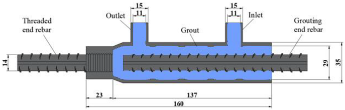 |
| GT14-DB-1d | 25/200/300/400/500/600 | End defect | 1d (14 mm) | 18 |  |
| GT14-DB-2d | 25/200/300/400/500/600 | End defect | 2d (28 mm) | 18 |  |
| GT14-DB-2.5d | 25/200/300/400/500/600 | End defect | 2.5d (35 mm) | 18 | 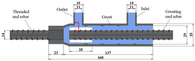 |
| GT14-DB-3d | 25/200/300/400/500/600 | End defect | 3d (42 mm) | 18 |  |
| GT14-ZB-2d | 25/200/300/400/500/600 | Middle defect | 2d (28 mm) | 18 |  |
| GT14-ZD-2d | 25/200/300/400/500/600 | Middle and end defect | 2d (28 mm) | 18 | 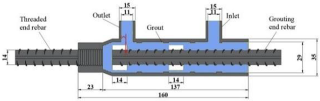 |
| GT14-PX | 25/200/300/400/500/600 | Deviated from the center 5 mm | / | 18 | 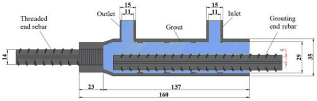 |
| Serial Number | L/mm | L1/mm | L2/mm | D1/mm | D2/mm | d1/mm | d2/mm | d3/mm | t/mm |
|---|---|---|---|---|---|---|---|---|---|
| GT JB414/14 | 160 | 23 | 137 | 29 | 35 | 11 | 15 | 14 | 3 |
| Temperature/°C | Average Flexural Tensile Strength/MPa | Average Compressive Strength/MPa | Reduction Factor |
|---|---|---|---|
| 25 | 11.75 | 87.3 | 100% |
| 200 | 10.35 | 77.9 | 89.2% |
| 300 | 7.34 | 74.4 | 85.8% |
| 400 | 5.60 | 66.8 | 76.6% |
| 500 | 4.11 | 63.3 | 72.5% |
| 600 | 3.73 | 46.7 | 53.5% |
| Temperature/°C | Yield Strength/MPa | Tensile Strength/MPa |
|---|---|---|
| 25 | 445 | 610 |
| 200 | 455 | 613 |
| 300 | 435 | 610 |
| 400 | 450 | 600 |
| 500 | 435 | 610 |
| 600 | 435 | 580 |
| Number | Fy/kN | Fu/kN | σ/MPa | ∆y/mm | ∆u/mm | Failure Mode |
|---|---|---|---|---|---|---|
| GT14-BM-25 | 68.47 | 93.87 | 610 | 2.91 | 84.53 | Rebar fracture |
| GT14-BM-200 | 67.6 | 93.7 | 609 | 3.12 | 75.85 | Rebar fracture |
| GT14-BM-300 | 68.4 | 93.67 | 608 | 3.17 | 82.14 | Rebar fracture |
| GT14-BM-400 | 67.9 | 92.5 | 601 | 3.09 | 76.37 | Rebar fracture |
| GT14-BM-500 | 67.2 | 92.02 | 598 | 2.56 | 69.27 | Rebar fracture |
| GT14-BM-600 | 63.48 | 81.9 | 532 | 3.25 | 35.83 | Rebar pulled-out |
| GT14-DB-1d-25 | 67.5 | 93.3 | 605 | 3.19 | 73.09 | Rebar fracture |
| GT14-DB-1d-200 | 68.8 | 92.75 | 601 | 3.52 | 71.42 | Rebar fracture |
| GT14-DB-1d-300 | 67.07 | 92.37 | 600 | 2.54 | 60.55 | Rebar fracture |
| GT14-DB-1d-400 | 67.5 | 88.26 | 573 | 3.21 | 61.5 | Rebar pulled-out |
| GT14-DB-1d-500 | 67.64 | 88.45 | 575 | 2.24 | 42.62 | Rebar pulled-out |
| GT14-DB-1d-600 | 65.23 | 81.34 | 528 | 2.53 | 30.74 | Rebar pulled-out |
| GT14-DB-2d-25 | 67.89 | 92.3 | 600 | 3.09 | 61.78 | Rebar fracture |
| GT14-DB-2d-200 | 67.75 | 92.07 | 598 | 2.67 | 55.43 | Rebar fracture |
| GT14-DB-2d-300 | 67.2 | 89.21 | 580 | 3.38 | 53.67 | Rebar fracture |
| GT14-DB-2d-400 | 66.69 | 87.86 | 571 | 3.09 | 54.2 | Rebar pulled-out |
| GT14-DB-2d-500 | 66.7 | 86.3 | 561 | 2.72 | 40.43 | Rebar pulled-out |
| GT14-DB-2d-600 | 65.6 | 79.08 | 514 | 3.38 | 27.64 | Rebar pulled-out |
| GT14-DB-2.5d-25 | 66.84 | 92.4 | 600 | 2.54 | 60.8 | Rebar pulled-out |
| GT14-DB-2.5d-200 | 67.2 | 90.33 | 587 | 3.21 | 49.45 | Rebar pulled-out |
| GT14-DB-2.5d-300 | 66.9 | 90.2 | 586 | 2.92 | 50.34 | Rebar pulled-out |
| GT14-DB-2.5d-400 | 66.5 | 85.46 | 555 | 2.97 | 43.6 | Rebar pulled-out |
| GT14-DB-2.5d-500 | 66.6 | 79.08 | 514 | 3.38 | 27.64 | Rebar pulled-out |
| GT14-DB-2.5d-600 | 66.2 | 75.77 | 492 | 2.54 | 19.71 | Rebar pulled-out |
| GT14-DB-3d-25 | 66.5 | 82.86 | 538 | 2.87 | 26.44 | Rebar pulled-out |
| GT14-DB-3d-200 | 64.53 | 80.56 | 523 | 3.29 | 23.13 | Rebar pulled-out |
| GT14-DB-3d-300 | 64 | 79.3 | 515 | 3.21 | 22.8 | Rebar pulled-out |
| GT14-DB-3d-400 | 67.34 | 74.1 | 481 | 3.62 | 17.84 | Rebar pulled-out |
| GT14-DB-3d-500 | 66.3 | 70.64 | 459 | 3.02 | 11.45 | Rebar pulled-out |
| GT14-DB-3d-600 | / | 58.29 | 379 | 2.33 | 4.29 | Rebar pulled-out |
| GT14-ZB-2d-25 | 67.14 | 88.9 | 578 | 3.29 | 72.34 | Rebar pulled-out |
| GT14-ZB-2d-200 | 67.24 | 88.67 | 576 | 3.79 | 53.95 | Rebar pulled-out |
| GT14-ZB-2d-300 | 66.4 | 88.26 | 573 | 2.91 | 40.7 | Rebar pulled-out |
| GT14-ZB-2d-400 | 67.8 | 84 | 546 | 2.72 | 36.85 | Rebar pulled-out |
| GT14-ZB-2d-500 | 67.18 | 82.19 | 534 | 3.22 | 33.23 | Rebar pulled-out |
| GT14-ZB-2d-600 | 63.15 | 68.87 | 447 | 1.70 | 18.61 | Rebar pulled-out |
| GT14-ZD-2d-25 | 66.4 | 86.23 | 560 | 2.64 | 35.12 | Rebar pulled-out |
| GT14-ZD-2d-200 | 66.2 | 82.59 | 537 | 3.11 | 32.86 | Rebar pulled-out |
| GT14-ZD-2d-300 | 63.61 | 83.09 | 540 | 3.08 | 29.56 | Rebar pulled-out |
| GT14-ZD-2d-400 | 66.19 | 82.16 | 534 | 2.81 | 27.79 | Rebar pulled-out |
| GT14-ZD-2d-500 | 64.39 | 78.76 | 512 | 1.95 | 24.22 | Rebar pulled-out |
| GT14-ZD-2d-600 | / | 60.4 | 392 | 2.68 | 5.24 | Rebar pulled-out |
| GT14-PX-25 | 68.16 | 93.6 | 608 | 2.64 | 77.65 | Rebar fracture |
| GT14-PX-200 | 67.5 | 93.1 | 605 | 2.91 | 74.57 | Rebar fracture |
| GT14-PX-300 | 67.63 | 92.37 | 600 | 2.54 | 67.67 | Rebar fracture |
| GT14-PX-400 | 67.79 | 90.1 | 585 | 3.09 | 66.02 | Rebar fracture |
| GT14-PX-500 | 69.92 | 90.08 | 585 | 3.01 | 55.90 | Rebar pulled-out |
| GT14-PX-600 | 64.3 | 81.4 | 529 | 3.25 | 28.17 | Rebar pulled-out |
| Number | Defect Types X1 | Temperature X2/°C | Ultimate Load X0/kN | |||||||
|---|---|---|---|---|---|---|---|---|---|---|
| 1 | GT14-BM | 200 | 93.7 | 1 | 1 | 1 | 0 | 0 | 1 | 1.00 |
| 2 | GT14-BM | 300 | 93.67 | 1 | 1.5 | 1 | 0 | 0.50 | 1 | 0.70 |
| 3 | GT14-BM | 400 | 92.5 | 1 | 2 | 0.99 | 0.01 | 1.01 | 0.99 | 0.54 |
| 4 | GT14-BM | 500 | 92.02 | 1 | 2.5 | 0.98 | 0.02 | 1.52 | 0.99 | 0.44 |
| 5 | GT14-BM | 600 | 81.9 | 1 | 3 | 0.87 | 0.13 | 2.13 | 0.90 | 0.36 |
| 6 | GT14-DB-1d | 200 | 92.75 | 0.88 | 1 | 0.99 | 0.11 | 0.01 | 0.92 | 0.99 |
| 7 | GT14-DB-1d | 300 | 92.37 | 0.88 | 1.5 | 0.99 | 0.10 | 0.51 | 0.92 | 0.70 |
| 8 | GT14-DB-1d | 400 | 88.26 | 0.88 | 2 | 0.94 | 0.06 | 1.06 | 0.95 | 0.53 |
| 9 | GT14-DB-1d | 500 | 88.45 | 0.88 | 2.5 | 0.94 | 0.06 | 1.56 | 0.95 | 0.43 |
| 10 | GT14-DB-1d | 600 | 81.34 | 0.88 | 3 | 0.87 | 0.02 | 2.13 | 0.99 | 0.36 |
| 11 | GT14-DB-2d | 200 | 92.07 | 0.77 | 1 | 0.98 | 0.22 | 0.02 | 0.85 | 0.99 |
| 12 | GT14-DB-2d | 300 | 89.21 | 0.77 | 1.5 | 0.95 | 0.19 | 0.55 | 0.87 | 0.68 |
| 13 | GT14-DB-2d | 400 | 87.86 | 0.77 | 2 | 0.94 | 0.17 | 1.06 | 0.87 | 0.53 |
| 14 | GT14-DB-2d | 500 | 86.3 | 0.77 | 2.5 | 0.92 | 0.15 | 1.58 | 0.89 | 0.43 |
| 15 | GT14-DB-2d | 600 | 79.08 | 0.77 | 3 | 0.84 | 0.08 | 2.16 | 0.94 | 0.36 |
| 16 | GT14-DB-2.5d | 200 | 90.33 | 0.71 | 1 | 0.96 | 0.26 | 0.04 | 0.82 | 0.97 |
| 17 | GT14-DB-2.5d | 300 | 90.2 | 0.71 | 1.5 | 0.96 | 0.25 | 0.54 | 0.82 | 0.69 |
| 18 | GT14-DB-2.5d | 400 | 85.46 | 0.71 | 2 | 0.91 | 0.20 | 1.09 | 0.85 | 0.52 |
| 19 | GT14-DB-2.5d | 500 | 79.08 | 0.71 | 2.5 | 0.84 | 0.14 | 1.66 | 0.90 | 0.42 |
| 20 | GT14-DB-2.5d | 600 | 75.77 | 0.71 | 3 | 0.81 | 0.10 | 2.19 | 0.92 | 0.35 |
| 21 | GT14-DB-3d | 200 | 80.56 | 0.65 | 1 | 0.86 | 0.21 | 0.14 | 0.85 | 0.89 |
| 22 | GT14-DB-3d | 300 | 79.3 | 0.65 | 1.5 | 0.85 | 0.20 | 0.65 | 0.86 | 0.65 |
| 23 | GT14-DB-3d | 400 | 74.1 | 0.65 | 2 | 0.79 | 0.14 | 1.21 | 0.89 | 0.50 |
| 24 | GT14-DB-3d | 500 | 70.64 | 0.65 | 2.5 | 0.75 | 0.10 | 1.75 | 0.92 | 0.41 |
| 25 | GT14-DB-3d | 600 | 58.29 | 0.65 | 3 | 0.62 | 0.03 | 2.38 | 0.98 | 0.33 |
| 26 | GT14-ZB-2d | 200 | 88.67 | 0.77 | 1 | 0.95 | 0.18 | 0.05 | 0.87 | 0.96 |
| 27 | GT14-ZB-2d | 300 | 88.26 | 0.77 | 1.5 | 0.94 | 0.18 | 0.56 | 0.87 | 0.68 |
| 28 | GT14-ZB-2d | 400 | 84 | 0.77 | 2 | 0.90 | 0.13 | 1.10 | 0.90 | 0.52 |
| 29 | GT14-ZB-2d | 500 | 82.19 | 0.77 | 2.5 | 0.88 | 0.11 | 1.62 | 0.92 | 0.42 |
| 30 | GT14-ZB-2d | 600 | 68.87 | 0.77 | 3 | 0.74 | 0.03 | 2.26 | 0.97 | 0.34 |
| 31 | GT14-ZD-2d | 200 | 82.59 | 0.77 | 1 | 0.88 | 0.11 | 0.12 | 0.91 | 0.91 |
| 32 | GT14-ZD-2d | 300 | 83.09 | 0.77 | 1.5 | 0.89 | 0.12 | 0.61 | 0.91 | 0.66 |
| 33 | GT14-ZD-2d | 400 | 82.16 | 0.77 | 2 | 0.88 | 0.11 | 1.12 | 0.92 | 0.53 |
| 34 | GT14-ZD-2d | 500 | 78.76 | 0.77 | 2.5 | 0.84 | 0.07 | 1.66 | 0.94 | 0.45 |
| 35 | GT14-ZD-2d | 600 | 60.4 | 0.77 | 3 | 0.64 | 0.12 | 2.36 | 0.91 | 0.34 |
| 36 | GT14-PX | 200 | 93.1 | 1 | 1 | 0.99 | 0.01 | 0.01 | 0.99 | 0.99 |
| 37 | GT14-PX | 300 | 92.37 | 1 | 1.5 | 0.99 | 0.01 | 0.51 | 0.99 | 0.70 |
| 38 | GT14-PX | 400 | 90.1 | 1 | 2 | 0.96 | 0.04 | 1.04 | 0.97 | 0.53 |
| 39 | GT14-PX | 500 | 90.08 | 1 | 2.5 | 0.96 | 0.04 | 1.54 | 0.97 | 0.44 |
| 40 | GT14-PX | 600 | 81.4 | 1 | 3 | 0.87 | 0.13 | 2.13 | 0.90 | 0.36 |
Disclaimer/Publisher’s Note: The statements, opinions and data contained in all publications are solely those of the individual author(s) and contributor(s) and not of MDPI and/or the editor(s). MDPI and/or the editor(s) disclaim responsibility for any injury to people or property resulting from any ideas, methods, instructions or products referred to in the content. |
© 2024 by the authors. Licensee MDPI, Basel, Switzerland. This article is an open access article distributed under the terms and conditions of the Creative Commons Attribution (CC BY) license (https://creativecommons.org/licenses/by/4.0/).
Share and Cite
Hu, S.; Jiang, S.; Chen, D.; Li, H.; Xu, T. Post-Fire Mechanical Properties of Half-Grouted Sleeve Connectors with Grouting Defects. Buildings 2024, 14, 1434. https://doi.org/10.3390/buildings14051434
Hu S, Jiang S, Chen D, Li H, Xu T. Post-Fire Mechanical Properties of Half-Grouted Sleeve Connectors with Grouting Defects. Buildings. 2024; 14(5):1434. https://doi.org/10.3390/buildings14051434
Chicago/Turabian StyleHu, Shouying, Shan Jiang, Dong Chen, Haoran Li, and Tao Xu. 2024. "Post-Fire Mechanical Properties of Half-Grouted Sleeve Connectors with Grouting Defects" Buildings 14, no. 5: 1434. https://doi.org/10.3390/buildings14051434
APA StyleHu, S., Jiang, S., Chen, D., Li, H., & Xu, T. (2024). Post-Fire Mechanical Properties of Half-Grouted Sleeve Connectors with Grouting Defects. Buildings, 14(5), 1434. https://doi.org/10.3390/buildings14051434