Abstract
Under human-induced excitations, a floor structure may suffer excessive vibrations due to its large span and low damping ratio. Vertical vibrations, in particular, can become intolerable during resonance events. A tuned mass damper (TMD) is a widely used single-degree-of-freedom dynamic vibration absorber. To enhance the serviceability of a floor structure, a multiple TMD (MTMD) system finds broad application. The parameters of the MTMD must be carefully designed to achieve satisfactory performance. However, existing studies often employ a simplified model of the floor structure with closely spaced modes to optimize the parameters of MTMD. Nonetheless, an oversimplified floor model can lead to a reduction in its control effect. To solve this problem, this study utilizes the OAPI facility of SAP2000 to build a connection with MATLAB. A multi-objective optimization algorithm based on the artificial fish swarm algorithm (AFSA) for MTMD is developed in MATLAB, while the finite element model of a real floor structure is built in SAP2000. The locations of the MTMD system are initially specified in SAP2000 and, through the proposed MATLAB–SAP2000 interface, data can be exchanged between them. Based on the structural dynamic responses to external excitations in SAP2000, the optimization process for the MTMD is carried out in MATLAB. Concurrently, the parameters of the MTMD in SAP2000 are iteratively adjusted until they reach their final optimal values. To underscore the enhancements brought about by the proposed interface and optimization method, a comparative case study is conducted. A group of MTMDs, optimized using a conventional method, is presented for reference. The numerical results indicate that, overall, the proposed MTMD system exhibits superior control effectiveness and robustness.
1. Introduction
With the acceleration of urban modernization and the rapid development of science and technology, modern architectural structure forms are developing towards larger volumes and spans [,,,]. Simultaneously, heightened demands are placed on the serviceability of structures. For sports venues where the floor structure possesses a lighter weight and lower damping ratio, the natural frequency tends to be lower [,,,,]. Considering the 1.6 Hz to 2.4 Hz human-induced excitation frequency range, when the excitation frequency closely aligns with the structural natural frequency, resonance phenomena can compromise user comfort and even evoke a sense of panic [,,,]. Most recently, serviceability evaluations on low-frequency floors, cross-laminated timber floors, concrete floors, lightweight timber floors, and reinforced concrete precast one-way joist floors can be found in [,,,,], respectively.
An appealing approach to improve the serviceability of a floor structure involves the application of additional structural control devices []. Among these, the TMD stands out as a popular SDOF dynamic vibration absorber [,,,]. In the case of a TMD with constant mass, its control effectiveness relies on both its frequency and damping ratio [,,,,]. Therefore, meticulous optimization of TMD parameters is essential to achieve satisfactory performance [,,]. Zhang and Zhang [] optimized a TMD for tall intake towers, simplifying the tower to a lumped mass model. Jimenez-Alonso et al. [] designed a TMD for a lively footbridge, employing a simplified SDOF system for the bridge. Though the designed TMD in these two references exhibited good control effectiveness, the error caused by the simplification of the model could affect the parameter optimization of the TMD. Rong and Lu [] developed an Abaqus-Python interface to optimize a particle TMD for a tower. In TMD optimization design, a more detailed model of the main structure leads to more accurate TMD optimization results and improved control effectiveness. Inspired by Ref. [], an interface between two commercial software programs can be devised to address issues arising from an overly simplified model. In recent years, the application of mesh-free techniques in dynamic analyses of rods, beams, and plates has gained interest among researchers, yielding more accurate results with the same number of nodes. Keivan et al. [,,], for instance, explored the prediction of the dynamic response of an elastically supported thin beam traversed by a moving mass.
Typically, a floor structure exhibits closely spaced modes, and human-induced excitations span a broad frequency range. In such cases, a MTMD system, composed of several TMDs with different frequencies, is known to yield more effective control than a single TMD [,,]. Wang et al. [] proposed an adaptive-passive variable mass MTMD for a floor slab. Liu et al. [] presented a MTMD system for a cantilevered floor. Zuo et al. [] optimized a MTMD for an offshore wind turbine. Jahangiri and Sun [] proposed a MTMD for an offshore floating wind turbine. Gaspar et al. [] proposed a MTMD to control the vibration of steel-concrete composite floors. Huang et al. [,] presented a shape memory alloy-based MTMD for a timber floor structure. From the literature review in this paragraph, it is evident that the optimization results of MTMD parameters are contingent on an accurate and precise structural model. However, the simplification of the structural model inevitably introduces errors that can diminish the control effectiveness of the MTMD.
In the literature mentioned above, the simplification of the structural model and the optimization of MTMD parameters are predominantly proposed using the business mathematics software MATLAB []. Simultaneously, the widely acclaimed and extensively used structural analysis program SAP2000 [] has been a focus of research, particularly in the realms of structural optimization and model updating based on the OAPI facility of SAP2000 connected to MATLAB. Through the developed MATLAB–SAP2000 interface, Dinh-Cong et al. [] updated the model and assessed the damage to full-scale structures. Minh et al. [] identified the damage in a 3D transmission tower. Artar et al. [] optimized the design of steel truss bridges. Miano et al. [] built fragility curves of existing reinforced concrete buildings. Optimization designs of 3D reinforced concrete frames, cold-formed steel frames, frame structures, RC counterfort retaining walls, tied-arch bridges, cable-stayed footbridge, framed structures, and geometrically nonlinear lattice structures can be found in [,], respectively.
It is evident that the MATLAB–SAP2000 interface has found widespread application in the field of structural engineering. However, its utilization in the realm of structural control is notably absent. In existing studies, the optimization of MTMD parameters relies on a simplified model of the floor structure. Nevertheless, this oversimplification can result in the diminished control effectiveness of the MTMD.
To address this gap and provide a solution, this paper introduces the development of a MATLAB–SAP2000 interface in Section 2. Additionally, a multi-objective optimization algorithm based on the AFSA [,] for MTMD, considering both maximum and root mean square (RMS) accelerations at selected measuring points, is proposed in Section 3. To validate the accuracy and efficacy of the developed interface and optimization algorithm, an SDOF system constructed in SAP2000 is initially tested in Section 4. Subsequently, a large-span floor structure is presented as a case study in Section 5, with TMD/MTMD designed through the conventional method included for comparison in Section 4 and Section 5. Finally, conclusions are drawn in Section 6.
2. Matlab–SAP2000 Interface
2.1. SAP2000-API
An excessively simplified model for the optimization of MTMD inevitably introduces errors, particularly for floor structures with closely spaced modes, thereby diminishing the control effectiveness of MTMD. To address this challenge, a MATLAB–SAP2000 interface is developed in this section. Leveraging this interface, the MTMD system can be optimized directly within the finite element model, resulting in higher precision and improved control effectiveness.
Utilizing the OAPI, users can employ various programming languages to manipulate the SAP2000 database. This significantly streamlines the modeling, analysis, optimization, extraction, and processing of SAP2000 calculation results, enabling seamless data connection and exchange with other software. The OAPI allows for two-way direct data conversion, facilitating the rapid and comprehensive import of large models. Furthermore, it permits multiple data exchange loops between different applications without the need to create a new model for each loop. Therefore, the OAPI module extends the innovative use of SAP2000 functionality, empowering developers to invoke the SAP2000 analysis and design engine through their own applications.
The main steps and codes of SAP2000-OAPI are shown in Figure 1.
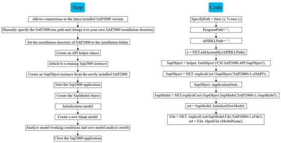
Figure 1.
Main steps and codes of SAP2000-OAPI.
2.2. MATLAB-SAP2000 Interface
It is mentioned in [,,] that at present, the current research indicates a lack of a universally accepted design method for the optimization of MTMD applied to floor structures. It is usually simplified into an SDOF system firstly according to the floor mode of interest, and then the traditional optimization design formula [,,,,,] is used for MTMD optimization. However, this widely employed simplified MTMD design method exhibits three main shortcomings: firstly, the modes of the floor structure are often closely spaced, and the simplification of multiple degrees of freedom to a single degree of freedom often leads to deviations; secondly, there is a lack of a widely accepted method to design the frequency and damping ratio of each TMD in the MTMD system; and thirdly, the actual vibration modes at the measuring points on the floor (i.e., the locations of each TMD in the MTMD) differ, and the simplified model fails to capture these differences between measuring points.
Hence, to mitigate the errors stemming from the simplification of floor structures in existing studies, this paper aims to directly utilize the floor finite element model in SAP2000 for the optimization of MTMD parameters through MATLAB. This approach is adopted to enhance the control effectiveness of MTMD in mitigating human-induced vibrations. The MATLAB-SAP2000 interface is developed upon the SAP2000-OAPI.
3. Parameter Optimization Algorithm of MTMD
MATLAB excels in conducting intelligent algorithm optimization for an objective function within specified parameters and a given range. However, it faces limitations in modeling and simplifying complex structures. On the other hand, SAP2000 is proficient in constructing a 3D finite element model, but it can only analyze under predefined models and parameter conditions, making direct optimization of MTMD parameters challenging. Therefore, by integrating these two software packages, a comprehensive approach can be achieved. After structural modeling, intelligent algorithm-based MTMD parameter optimization and structure analysis can be conducted, enabling applications across a broader spectrum of engineering scenarios.
In this paper, we have chosen MATLAB version 2020 [] and SAP2000 version 2022 [] software to develop the “interface function”, introducing a methodology that leverages the joint utilization of these two software tools. Structural modeling is conducted in SAP2000 and MTMD parameter optimization is performed in MATLAB, with seamless data transfer between the two platforms. Subsequently, MATLAB can automatically invoke the structural model in SAP2000 for MTMD parameter optimization and structural analysis.
The optimization outcomes and the effectiveness of vibration mitigation through MTMD are intricately tied to the chosen optimization target. In a bid to enhance the control effectiveness and robustness of the MTMD system for human-induced vibration control, this section introduces a multi-objective optimization algorithm. The algorithm integrates the AFSA [,] with the MATLAB-SAP2000 interface. The proposed method addresses the limitation of the direct application of intelligent optimization algorithms in actual engineering calculations. It significantly reduces the computational load, streamlining the MTMD parameter optimization process to be quicker, more convenient, and more accurate.
3.1. Artificial Fish Warm Algorithms
To expedite and enhance the effectiveness of MTMD parameter optimization, this section employs the AFSA for searching optimal parameters. AFSA is crafted based on the foraging, swarming, following, and random behavior of fish, presenting advantages such as strong flexibility, rapid convergence, high accuracy, and robust fault tolerance.
Four key parameters in the algorithm significantly influence convergence, namely visual range, step size, the number of artificial fish, and the number of attempts. Therefore, careful selection of these parameters is essential based on the specific situation and function.
The visual range parameter directly impacts algorithm convergence. Following the assessment of the fish swarm algorithm case and multiple attempts, this study determines a visual range of 0.5.
The step size parameter, influencing convergence speed and accuracy, requires a balance. A large value accelerates convergence but risks missing the optimal solution, leading to longer convergence times. On the other hand, a small value improves accuracy but may hinder algorithm convergence. Considering both speed and accuracy, along with the visual range, multiple trial calculations establish a step size of 1 in this paper.
The number of artificial fish directly affects the algorithm’s convergence speed. A higher number accelerates convergence but increases the iterative calculation load, impacting computational efficiency. After several trial calculations, the number of artificial fish is set at 80 in this section.
Lastly, the number of attempts influences foraging ability and convergence efficiency. A higher number strengthens foraging ability but raises the risk of local extreme values. After considering the case and the factors mentioned above, the number of attempts is determined to be 50 in Section 4.2 and 300 in Section 5.3 in the subsequent 3D model analysis.
3.2. Parameter Optimization Based on the Interface and AFSA
Regarding the serviceability problem, the typical focus is on the structural acceleration response. In this context, the maximum and RMS accelerations stand out as two crucial indices. In the pursuit of an MTMD system with heightened robustness and superior control effectiveness, both of these indices are taken into consideration. The objective function for the TMD in the system is shown in Equation (1).
where and are the two weight coefficients for the maximum and RMS accelerations, respectively, and are the mean maximum and RMS acceleration objective functions, respectively, and and represent the frequency and damping ratio of the TMD in the MTMD system, respectively.
In Equation (1), under several external excitations for optimization, normalized objective functions for the TMD are:
where and are the maximum values of the maximum structural accelerations of different excitations at the measuring point where the TMD is located, without and with the TMD, respectively, while and represent the maximum values of the RMS responses of different excitations, respectively. It should be noted that and are probably not from the same external excitation case, and it is likely that the excitation frequencies of these two cases are different. and are not necessarily from the same excitation case either.
Then, from Equations (2) and (3), it can be found that when the objective functional value is 1.0, it means that the TMD can completely kill the vibration at the corresponding structural measuring point. Therefore, the TMD will have a better control effect when the value is larger.
In Equation (1), the sum of and is 1.0, which means that for the TMD is also a normalized objective function. When is 1 and is 0, it means that only the maximum acceleration is considered, and it becomes a single-objective optimization problem. In this paper, they are both set to 0.5 as an example.
The suggested placement of each TMD in the MTMD system on the floor should align with the structural modal shape. Following the determination of the mass for each TMD in the MTMD system, the stiffness and damping coefficients can be optimized using the proposed algorithm, as depicted in Figure 2.
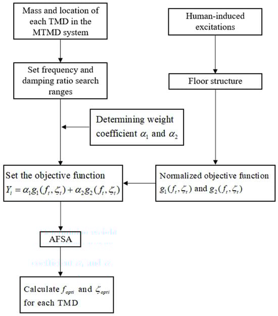
Figure 2.
Multi-objective optimization algorithm for MTMD based on AFSA.
Through the multi-objective optimization algorithm proposed in Figure 2, the optimal frequency ratio and the damping ratio for each TMD can be searched, and an optimized MTMD system is obtained.
Hence, the AFSA-based multi-objective optimization algorithm for MTMD using the developed MATLAB-SAP2000 interface is outlined in Figure 3. The floor structure and the initial MTMD system are initially constructed in SAP2000. Subsequently, under various human-induced excitations in SAP2000 for optimization purposes, structural acceleration responses can be seamlessly transferred to MATLAB. For the ith step, swarming and following behaviors of the artificial fish are carried out to search for a larger objective functional value in Equation (1). In correspondence with this step, adjustments are made to the parameters of the MTMD in SAP2000. The adaptability evaluation aims to assess whether a globally optimal solution has been reached. If affirmative, the entire joint optimization process concludes. Additionally, the optimization process concludes when a predetermined maximum number of steps has been attempted.
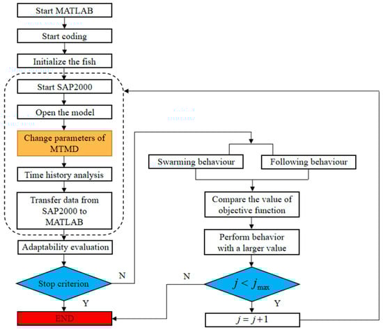
Figure 3.
Flow chart of the MATLAB-SAP2000 interface for MTMD optimization.
4. SDOF System Verification
4.1. Model Introduction
To validate the accuracy of the developed interface and optimization algorithm, in this section, a mass-spring-dashpot SDOF system built in SAP2000 is tested. The mass is set to 100 t, stiffness is 15,791 kN/m, indicating a natural frequency of 2.0 Hz, and a damping ratio of 1.0% is used, which is a typical model for a slender pedestrian structure.
The comfort design is based on [,]. According to [,], for pedestrian structures, the vertical load per unit area can be expressed as:
where is the vertical load of a single pedestrian and the value is 0.28 kN, means the frequency of the human-induced excitation, and represents the equivalent pedestrian density, and can be expressed as:
where is the area of the pedestrian structure, and are the structural damping ratio and the number of total pedestrians, respectively, and is the vertical load scale factor, which is shown in Figure 4.
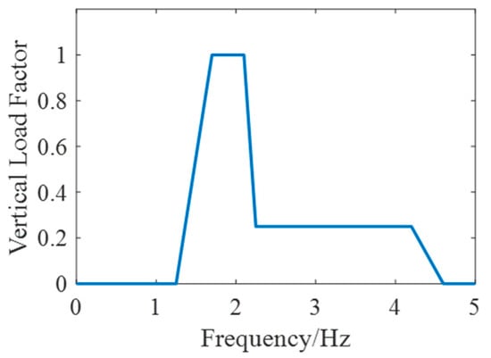
Figure 4.
Vertical load reduction coefficient.
To meticulously assess the performance of the pedestrian structure under walking-induced excitation, the model is subjected to harmonic excitations ranging from 1.25 to 4.60 Hz, with an equal interval of 0.05 Hz, resulting in a total of 68 cases based on Equation (4). It is important to note that this section considers the scenario with only one pedestrian.
4.2. Parameter Optimization of TMD
A TMD with a mass ratio of 1% is proposed as an example. The frequency searching range of TMD is set to be [0, 4 Hz], while the range of the damping ratio is set to be [0, 0.1]. Employing the optimization method outlined in Figure 4, the objective is to optimize the TMD to minimize both the maximum and RMS acceleration responses of the main structure under various excitations with different frequencies. The AFSA-based parameter searching is carried out in MATLAB while the SDOF main structure with a TMD is built in SAP2000, and they are connected through the developed interface. The optimization process can be seen in Figure 5.
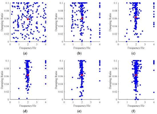
Figure 5.
Iterative process of the TMD parameter for the SDOF system: (a) Initial parameter distribution; (b) Step 5; (c) Step 10; (d) Step 15; (e) Step 20; (f) Step 50.
In Figure 5, the proposed MATLAB-SAP2000 interface facilitates seamless data transfer between the two platforms. The optimization process for MTMD is conducted in MATLAB based on structural dynamic responses under external excitations in SAP2000. The parameters of MTMD in SAP2000 are adjusted iteratively until reaching the final optimal values. In each iterative step, the ASFA depicts the convergence trajectory of the optimization process. The blue dots represent the distribution of TMD parameters for the current iteration, while the red dots represent the optimal TMD parameters for that iteration. Initially, the distribution of fish is scattered, but as the iterations progress, the fish swarm gradually converges towards the center, particularly around the frequency band of 2 Hz. Analyzing the position of the red dot in each subgraph and its slight variations reveals that the target function in Equation (1) is more sensitive to the frequency ratio than the damping ratio in this case. It is evident that the target function reaches its optimal value at approximately the 10th step due to the consistent location, with a frequency of 1.98 Hz and a damping ratio of 6.06%.
From Figure 6, with only a few iterations, the optimization method proposed in this study can quickly find the optimal frequency and damping ratio of TMD. Den Hartog [,,,] provided optimal formulas for the frequency ratio and damping ratio in an undamped SDOF system, but this paper focus on damped systems. In this regard, Warburton [,] conducted numerical studies and provided results for reference.
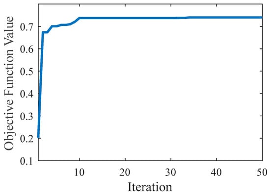
Figure 6.
Objective function value with the process of iteration.
For a given TMD mass ratio , structural damping ratio , TMD structure frequency ratio , excitation-structure frequency ratio , or TMD damping ratio , the optimization objective is to find the minimum acceleration response of the system under harmonic excitation. The response is defined by Equations (6)–(10).
The optimal frequency ratio and damping ratio should be chosen to minimize the peak value of . Substituting the known variables into the equations, we can obtain the optimal and damping ratio through numerical analysis methods.
According to Equations (6)–(10), when , we can obtain and , respectively. The optimized results are 1.98 Hz and 6.06%, respectively, which are nearly the same. Therefore, through a SDOF main structure, it has been verified in this section that the proposed AFSA-based multi-objective optimization algorithm for MTMD using the developed MATLAB-SAP2000 interface has the advantages of good convergence, fast convergence speed, and high precision.
5. Case Study
5.1. Case Introduction
To further illustrate the improvement of the proposed method in the optimization design of MTMD parameters used for vibration control of floor structures, this section takes a large-span floor structure as an example.
The proposed floor structure has a plane size of 67.6 m × 43.0 m. It is a steel frame structure. The thickness of the passageway floor is 120 mm, the thickness of the roof floor is 150 mm, and the floor material is concrete C30. The structure’s frame column adopts a 700 mm × 700 mm steel-reinforced concrete column, the material of the steel pipe is Q355, and material of the concrete is C50. The inclined strut mainly adopts 600 × 600 × 35 × 35 mm, 500 × 500 × 25 × 25 mm, BRB-120 × 120, BRB-180 × 180, and other box section steel, and the material is Q355. The frame beam is mainly made of 1100 × 600 × 35 × 35 mm, 900 × 600 × 30 × 30 mm, 600 × 450 × 14 × 30 mm H-beams and other sections, whose material is Q355. The total mass of the structure is 10,164 t. The finite element model of the floor structure is built in SAP2000 and shown in Figure 7.
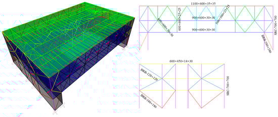
Figure 7.
The 3D view of the floor structure in SAP2000.
5.2. Conventional Design Method
In the conventional design approach for MTMD in a floor structure, the typical procedure involves conducting an initial modal analysis. Subsequently, the mode that is particularly sensitive to human-induced excitation is treated as a SDOF damped system, and the TMD can be optimized using formulas by Warburton. However, when dealing with MDOF floor structures characterized by densely spaced modal features, using the above-mentioned formulas cannot yield optimal results. The reason is that utilizing these formulas requires transforming the MDOF floor system into an equivalent SDOF system, which involves accurately assessing modal mass for the modes of interest. For a complex floor structure, achieving a precise equivalent SDOF system is challenging and the dynamic characteristics of the simplified SDOF model are different from those of the 3D model to some extent. This equivalence process introduces deviations, preventing the optimal vibration reduction effects when applying these formulas to 3D floor structures.
The structural mode shapes, sensitive to human-induced excitations, are depicted in Figure 8, with detailed information listed in Table 1. Figure 8 illustrates the vertical mode shape deformation of the entire floor structure. It is important to note that even though pedestrians exert force solely on the first floor, the connected inclined strut causes the second floor to influence the modal shape and frequency of the first floor. Consequently, a joint analysis of both floors is necessary.
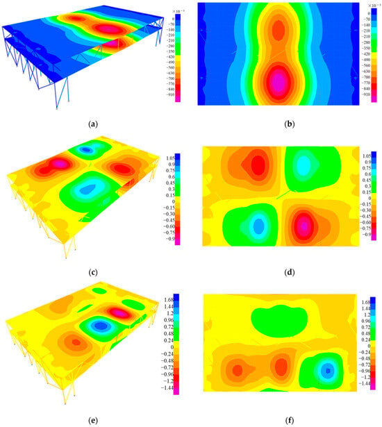
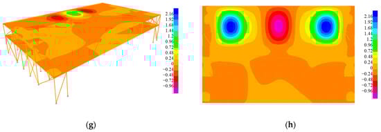
Figure 8.
Mode shapes: (a,b) Structural and the first floor’s first mode; (c,d) Structural and the first floor’s fourth mode; (e,f) Structural and the first floor’s fifteenth mode; (g,h) Structural and the first floor’s sixteenth mode.

Table 1.
Structural modal information.
From Figure 8 and Table 1, the first natural frequency is close to the fourth natural frequency, while the fifteenth natural frequency is close to the sixteenth natural frequency, which increases the difficulty of conventional design.
Based on the mode shapes presented in Figure 8 and considering that TMDs should be implemented where the modal response is maximum, a MTMD system comprising ten TMDs is proposed in Figure 9. It is worth noting that, for the ease of optimizing MTMD parameters and facilitating production processing, these TMDs are divided into three groups. TMDs within the same group share identical parameters.
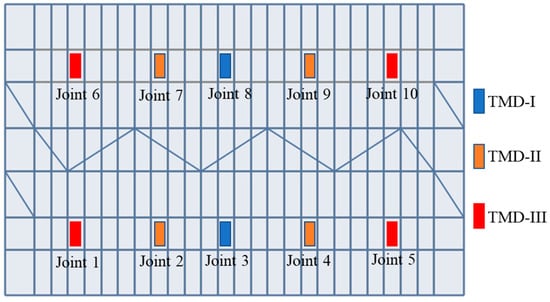
Figure 9.
The layout of the MTMD system on the first floor.
By comparing Figure 8 and Figure 9, TMD-I is used to control the first mode, but the location will be affected by the fifteenth and sixteenth modes as well. TMD-II is aimed at the fourth mode. TMD-III is mainly applied to control the fifteenth and sixteenth modes.
According to Table 1, the MTMD system is designed based on Equations (6)–(10), while the results are shown in Table 2. Note that the sixteenth mode is merged into the fifteenth mode while TMD-III is aimed at controlling it in the conventional design.
Table 2.
Conventional design results of the MTMD system.
5.3. Proposed Design Method
As discussed in Section 5.2, the conventional design method for MTMD relies on a simplified model of a floor structure with closely spaced modes, and an overly simplified floor model may result in a diminished control effect. In this section, the efficacy of the proposed AFSA-based multi-objective optimization algorithm for MTMD, utilizing the developed MATLAB-SAP2000 interface, is evaluated in the context of this floor structure.
In Equation (5), the area of the first floor is 1079 m2, as indicated in [], and the total number of pedestrians is half of this area, amounting to 540. To assess the performance of the pedestrian structure under human-induced excitation, the model undergoes harmonic excitations ranging from 1.25 Hz to 4.60 Hz, with an incremental difference of 0.05 Hz, resulting in a total of 68 cases based on Equation (4).
The parameter searching using the AFSA is conducted in MATLAB. Simultaneously, the floor structure with the MTMD system is constructed in SAP2000, and the two components are interconnected through the developed interface. The optimization process is illustrated in Figure 10. The frequency searching range for each TMD is set between 1 Hz and 3.5 Hz, while the range of the damping ratio is established as [0, 0.15].
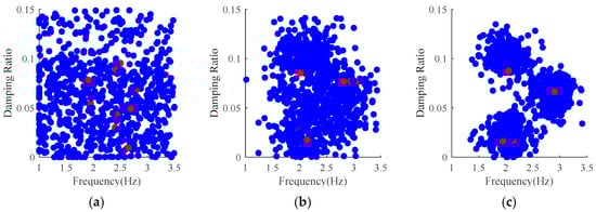
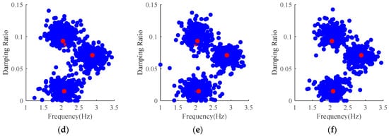
Figure 10.
Iterative process of the MTMD system on the floor structure: (a) Initial parameter distribution; (b) Step 10; (c) Step 50; (d) Step 100; (e) Step 200; (f) Step 300.
Through the established MATLAB-SAP2000 interface, data seamlessly transfers between the two platforms. The optimization process for the MTMD is executed in MATLAB based on structural dynamic responses under external excitations in SAP2000. Parameters of the MTMD in SAP2000 are adjusted iteratively until reaching the final optimal values. As depicted in Figure 10, with the progression of iterations, the initially scattered fish swarm gradually converges into three distinct groups, corresponding to the optimal frequency and damping ratio for the three types of TMDs illustrated in Figure 9. In each iteration step, the three red dots symbolize the optimal TMD parameters for the three types of TMDs, as presented in Table 3.
Table 3.
Optimal parameters of the three types of TMD in each iteration step.
Observing Table 3, it becomes apparent that with the advancement of iterations, the optimal parameters of the MTMD gradually stabilize. The results are summarized in Table 4, and the entire iterative process is depicted in Figure 11. A comparison between Table 2 and Table 4 reveals that the frequencies of the proposed optimized MTMD are consistently smaller than the values obtained through the conventional design method. Notably, there is a substantial difference in their optimal damping ratios. A comparative analysis of their human-induced vibration control effects will be conducted in the subsequent section.
Table 4.
Optimized parameters of the MTMD system by the proposed method.
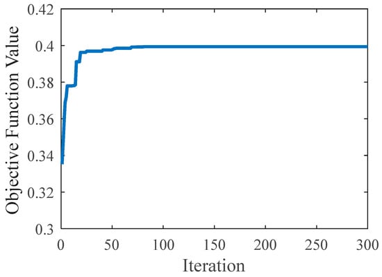
Figure 11.
Objective function value with the process of iteration of the MTMD system.
Analyzing Figure 11 reveals that after step 100, the value of the objective function remains constant, signifying that the iteration has converged. Hence, for a full-scale floor structure, this section provides verification that the proposed AFSA-based multi-objective optimization algorithm for MTMD, employing the developed MATLAB-SAP2000 interface, exhibits robust convergence characteristics.
For the real-scale floor structure model in Figure 9, when optimizing the MTMD system consisting of 10 TMDs, the CPU of the computer used in this paper is 3.50 GHz, the RAM is 64.0 GB, and the calculation time is about 20 h.
5.4. Comparison of the Control Effect
In this section, the human-induced vibration control effects of the MTMD from Section 5.2 and Section 5.3 are compared to emphasize the enhancements brought about by the proposed method. The comparison focuses on structural acceleration spectra under various human-induced excitations with different frequencies, as illustrated by the ten measuring points in Figure 9, now presented in Figure 12.
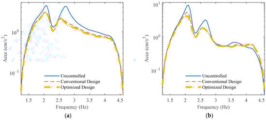
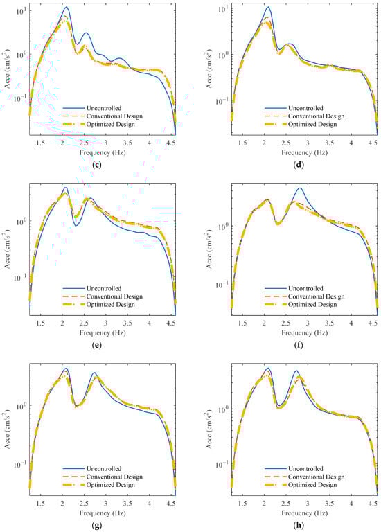
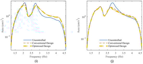
Figure 12.
Comparison of the structural acceleration spectra: (a) Point 1; (b) Point 2; (c) Point 3; (d) Point 4; (e) Point 5; (f) Point 6; (g) Point 7; (h) Point 8; (i) Point 9; (j) Point 10.
As can be seen from Figure 12, although the 10 measuring points are all situated on the same span of the floor structure, their acceleration spectrum shapes and response values are different. For measuring points 1, 7, 8, and 9, there are obviously two peaks close to the same height, that is, they are affected by multiple local vertical modes at the same time. Meanwhile, the MTMD optimized in this study has a better control effect than the MTMD optimized by the conventional method, which is especially reflected in the attenuation of the first peak at around 2.0 Hz at points 2~4 and the second peak at around 2.8 Hz at point 6 and point 10. It is worth noting in Figure 12e that for point 5, in the frequency range of 2.2 Hz to 2.6 Hz, the response of the uncontrolled structure is smaller than the response after adding the MTMDs. When MTMDs are used to control vibration at a specific frequency, they can achieve better control effects just at the frequency at the peak point. However, in a frequency range near that frequency, there may be a certain degree of response amplification. This is because the added MTMDs alter the whole structure’s modes, causing a shift in the structural modal frequencies. As a result, the resonance effect near the central frequency is enhanced, leading to the possibility of response amplification, or even leading to the appearance of two new peaks. These can explain why the response of the controlled structure between the frequencies at two peak points, around 2.2 Hz to 2.6 Hz, is larger than the uncontrolled structure. What is more, in Figure 12e, the peak responses of the conventional designed controlled structure and optimized designed controlled structure are both smaller than that of the uncontrolled structure.
Figure 12 shows that the optimized parameters outperform the conventional method. Since the optimized method employs the 3D model to run an iterative computation, the results can be regarded as optimal. The conventional method, although using the optimal formula, is designed for a SDOF system. This requires us to simplify the MDOF system and find an equivalent SDOF system instead. The equivalent simplification introduces computational deviations, preventing the parameters in this formula from achieving optimal solutions. Additionally, the vibration reduction effects of MTMD in the actual MDOF model interact with each other, and this cannot be reflected in these formulas.
In Figure 12, the maximum accelerations of the case without MTMD, with the conventional designed MTMD, and with the proposed MTMD of each subgraph are compared in Table 5, while reductions of the two MTMD systems are presented in Table 6.
Table 5.
Comparison of the maximum accelerations at the measuring points.
Table 6.
Comparison of the reductions of different MTMDs at the measuring points.
It is evident from Table 5 and Table 6 that the proposed optimization method significantly enhances the control effectiveness of the MTMD compared to the conventional design method. Notably, the maximum reduction achieved by the conventionally designed MTMD is 50.10%, while the proposed MTMD achieves a remarkable maximum reduction of 65.51%. Specifically, for measuring points 7–9, the reduction provided by the proposed MTMD is more than twice that achieved by the conventional design method.
When the structure resonates, its vibration response is maximized, and the vibration reduction of the TMD with optimized parameters is at its maximum. When the external excitation frequency deviates from the resonance interval, the response of the structure is significantly reduced, leading to a reduction in the control effect of the TMD. Upon comparing Table 5 and Table 6, it becomes apparent that for point 2, point 3, and point 4, where the acceleration response is most pronounced, the control effect of the MTMD is more significant and the optimized MTMD in this paper demonstrates superior control effectiveness. For other measurement points where the acceleration response of the structure is smaller, and the vibration mitigation effect of the MTMD is less pronounced, the MTMD system proposed in this paper still exhibits better vibration reduction performance than the MTMD system obtained through the conventional design method.
Finally, acceleration time history is compared in Figure 13. As for points 1–5 and 7–9, the excitation frequency is 2.10 Hz, while it is 2.80 Hz for points 6 and 10.
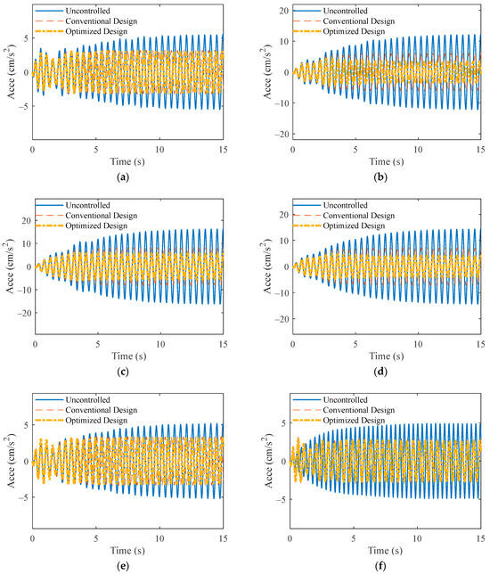
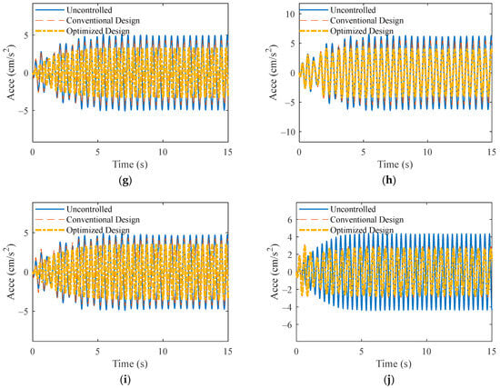
Figure 13.
Comparison of the structural acceleration time histories: (a) Point 1; (b) Point 2; (c) Point 3; (d) Point 4; (e) Point 5; (f) Point 6; (g) Point 7; (h) Point 8; (i) Point 9; (j) Point 10.
In Figure 13, it is obvious that the proposed MTMD system has a better human-induced vibration control effect at points 2–4 and points 7–9.
In Section 4, for a SDOF damped structure, the proposed method obtains an optimized TMD almost the same as the TMD from the work of G.B. Warburton [,]. However, in this section, for a full-scale floor structure, the proposed method obtains an optimized MTMD system which is more effective than the conventional designed MTMD system based on the Warburton formula. This indicates that the Warburton formulas have certain limitations when applied to MDOF systems. One of the reasons for the deviations is the process of transforming a MDOF system into a SDOF equivalent. Additionally, these formulas cannot consider the mutual influence between MTMDs at different locations. In practice, to obtain optimal parameters for MTMD in a MDOF system, the use of interface-based algorithm optimization is a good example.
In this study, the commonly used industrial software, SAP2000, was utilized as an interface for optimization design. This did not significantly increase time or manpower costs, yet it facilitated the optimal design of MTMD. Further, the proposed AFSA-based multi-objective optimization algorithm for MTMD can improve its control effect as well.
6. Conclusions
To enhance the serviceability of a floor structure, the application of a MTMD system is widespread. The parameters of the MTMD should be meticulously designed to achieve satisfactory performance. However, the prevalent use of a simplified model for the floor structure with closely spaced modes in optimizing MTMD parameters may result in a diminished control effect.
To address this challenge, the present study utilizes the OAPI feature of SAP2000 to establish a connection with MATLAB. A multi-objective optimization algorithm, based on the AFSA, is developed in MATLAB, while the finite element model of an actual floor structure is constructed in SAP2000. Initial positions for the MTMD system are designated in SAP2000. Subsequently, through the devised MATLAB-SAP2000 interface, data can be seamlessly exchanged between the two platforms. The optimization process for the MTMD is conducted in MATLAB based on structural dynamic responses obtained from SAP2000, and the parameters of the MTMD in SAP2000 are finely tuned until reaching the ultimate optimal values.
Through two numerical simulations, the following conclusions can be drawn:
- (1)
- Through a SDOF main structure, it has been verified in this section that the proposed AFSA-based multi-objective optimization algorithm for TMD using the developed MATLAB-SAP2000 interface has the advantages of good convergence, fast convergence speed, and high precision. The proposed method obtains an optimized TMD almost the same as the TMD from the Warburton formulas.
- (2)
- For a full-scale floor structure, the proposed method obtains an optimized MTMD system, and the iterative process has a good convergence as well.
- (3)
- During the conventional design, the simplification and neglect of the modal information of the floor structure will bring bias to the parameter design of MTMD and reduce its control effect, while the developed MATLAB-SAP2000 interface can solve this problem perfectly. Further, the proposed AFSA-based multi-objective optimization algorithm for MTMD can improve its control effect as well.
- (4)
- The proposed optimization method can improve the control effect and robustness of MTMD to a great degree compared to the conventional design method. In a further study, the application of a semi-active MTMD system in the 3D finite element model directly using the developed interface is worthy of investigation.
Author Contributions
Conceptualization, W.S.; methodology, W.S.; software, Q.Z. and Y.W.; validation, W.S., Q.Z. and Y.W.; formal analysis, Q.Z. and Y.W.; investigation, Y.W.; resources, Y.W.; data curation, Y.W.; writing—original draft preparation, Q.Z.; writing—review and editing, Q.Z.; visualization, Q.Z.; supervision, W.S.; project administration, W.S.; funding acquisition, W.S. All authors have read and agreed to the published version of the manuscript.
Funding
This research was funded by the National Natural Science Foundation of China (Grant No. 52308526), National Key Research and Development Program of China (Grant No. 2022YFF0608903), Shanghai Pujiang Program (Grant No. 22PJ1413600), and the Fundamental Research Funds for the Central Universities (Grant Nos. 22120220573 and 0200121005/174).
Data Availability Statement
Data are available from the corresponding author and can be shared upon reasonable request. The data are not publicly available due to confidentiality.
Conflicts of Interest
The authors declare no conflicts of interest.
References
- Wang, L.; Nagarajaiah, S.; Zhou, Y.; Shi, W. Experimental study on adaptive-passive tuned mass damper with variable stiffness for vertical human-induced vibration control. Eng. Struct. 2023, 280, 115714. [Google Scholar] [CrossRef]
- Casciati, F.; Casciati, S.; Faravelli, L. A contribution to the modelling of human induced excitation on pedestrian bridges. Struct. Saf. 2017, 66, 51–61. [Google Scholar] [CrossRef]
- Shi, W.; Wang, L.; Lu, Z. Study on self-adjustable tuned mass damper with variable mass. Struct. Control Health Monit. 2018, 25, e2114. [Google Scholar] [CrossRef]
- Wei, X. A simplified method to account for human-human interaction in the prediction of pedestrian-induced vibrations. Struct. Control Health Monit. 2021, 28, e2753. [Google Scholar] [CrossRef]
- Shi, W.; Wang, L.; Lu, Z.; Wang, H. Experimental and numerical study on adaptive-passive variable mass tuned mass damper. J. Sound Vib. 2019, 452, 97–111. [Google Scholar] [CrossRef]
- Costa-Neves, L.F.; da Silva, J.G.S.; de Lima, L.R.O.; Jordão, S. Multi-storey, multi-bay buildings with composite steel-deck floors under human-induced loads: The human comfort issue. Comput. Struct. 2014, 136, 34–46. [Google Scholar] [CrossRef]
- Xie, Z.; Hu, X.; Du, H.; Zhang, X. Vibration behavior of timber-concrete composite floors under human-induced excitation. J. Build. Eng. 2020, 32, 101744. [Google Scholar] [CrossRef]
- Nguyen, K.; Freytag, B.; Ralbovsky, M.; Rio, O. Assessment of serviceability limit state of vibrations in the UHPFRC-Wild bridge through an updated FEM using vehicle-bridge interaction. Comput. Struct. 2015, 156, 29–41. [Google Scholar] [CrossRef]
- Wang, Y.; Wang, L.; Shi, W. Two-dimensional air spring based semi-active TMD for vertical and lateral walking and wind-induced vibration control. Struct. Eng. Mech. 2021, 80, 377–390. [Google Scholar]
- Celik, O.; Dong, C.; Catbas, F.N. A computer vision approach for the load time history estimation of lively individuals and crowds. Comput. Struct. 2018, 200, 32–52. [Google Scholar] [CrossRef]
- Wang, L.; Nagarajaiah, S.; Shi, W.; Zhou, Y. Semi-active control of walking-induced vibrations using adaptive tuned mass damper considering human-structure-interaction. Eng. Struct. 2021, 244, 112743. [Google Scholar] [CrossRef]
- Racic, V.; Chen, J. Data-driven generator of stochastic dynamic loading due to people bouncing. Comput. Struct. 2015, 158, 240–250. [Google Scholar] [CrossRef]
- Shi, W.; Wang, L.; Lu, Z.; Gao, H. Study on adaptive-passive and semi-active eddy current tuned mass damper with variable damping. Sustainability 2018, 10, 99. [Google Scholar] [CrossRef]
- Van Engelen, N.C.; Graham, J. Comparison of prediction and measurement techniques for pedestrian-induced vibrations of a low-frequency floor. Struct. Control Health Monit. 2019, 26, e2294. [Google Scholar] [CrossRef]
- Hassan, O.A.B.; Öberg, F.; Gezelius, E. Cross-laminated timber flooring and concrete slab flooring: A comparative study of structural design, economic and environmental consequences. J. Build. Eng. 2019, 26, 100881. [Google Scholar] [CrossRef]
- Ussher, E.; Arjomandi, K.; Smith, I. Status of vibration serviceability design methods for lightweight timber floors. J. Build. Eng. 2022, 50, 104111. [Google Scholar] [CrossRef]
- Caballero-Garatachea, O.; Juarez-Luna, G.; Sandoval-Hernandez, M.E.R. Methods for the vibration analysis of reinforced concrete precast one-way joist slab floor systems under human walking. J. Build. Eng. 2021, 43, 103217. [Google Scholar] [CrossRef]
- He, W.; Xie, W. Characterization of stationary and walking people on vertical dynamic properties of a lively lightweight bridge. Struct. Control Health Monit. 2018, 25, e2123. [Google Scholar] [CrossRef]
- Gao, Z.; Zhao, M.; Wu, Y.; Wang, M.; Du, X. Parameter design and performance evaluation of tuned mass damper (TMD) for seismic control of structure considering soil-structure interaction (SSI). Structures 2023, 52, 1116–1129. [Google Scholar] [CrossRef]
- Wang, L.; Shi, W.; Zhou, Y. Study on self-adjustable variable pendulum tuned mass damper. Struct. Des. Tall Spec. Build. 2019, 28, e1561. [Google Scholar] [CrossRef]
- Zhang, H.; Wang, L.; Shi, W. Seismic control of adaptive variable stiffness intelligent structures using fuzzy control strategy combined with LSTM. J. Build. Eng. 2023, 78, 107549. [Google Scholar] [CrossRef]
- Cao, L.; Li, C. Tuned tandem mass dampers-inerters with broadband high effectiveness for structures under white noise base excitations. Struct. Control Health Monit. 2019, 26, e2319. [Google Scholar] [CrossRef]
- Wang, L.; Nagarajaiah, S.; Shi, W.; Zhou, Y. Seismic performance improvement of base-isolated structures using a semi-active tuned mass damper. Eng. Struct. 2022, 271, 114963. [Google Scholar] [CrossRef]
- Wang, L.; Shi, W.; Li, X.; Zhang, Q.; Zhou, Y. An adaptive-passive retuning device for a pendulum tuned mass damper considering mass uncertainty and optimum frequency. Struct. Control Health Monit. 2019, 26, e2377. [Google Scholar] [CrossRef]
- Wang, M.; Sun, F.; Koetaka, Y.; Chen, L.; Nagarajaiah, S.; Du, X. Frequency independent damped outrigger systems for multi-mode seismic control of super tall buildings with frequency independent negative stiffness enhancement. Earthq. Eng. Struct. Dyn. 2023, 52, 2731–2754. [Google Scholar] [CrossRef]
- Wang, L.; Zhou, Y.; Nagarajaiah, S.; Shi, W. Bi-directional semi-active tuned mass damper for torsional asymmetric structural seismic response control. Eng. Struct. 2023, 294, 116744. [Google Scholar] [CrossRef]
- Wang, L.; Zhou, Y.; Shi, W. Seismic response control of a nonlinear tall building under mainshock-aftershock sequences using semi-active tuned mass damper. Int. J. Struct. Stab. Dyn. 2023, 23, 2340027. [Google Scholar] [CrossRef]
- Wang, L.; Zhou, Y.; Shi, W. Seismic control of a smart structure with semi-active tuned mass damper and adaptive stiffness property. Earthq. Eng. Resil. 2023, 2, 74–93. [Google Scholar]
- Wang, L.; Nagarajaiah, S.; Shi, W.; Zhou, Y. Study on adaptive-passive eddy current pendulum tuned mass damper for wind-induced vibration control. Struct. Des. Tall Spec. Build. 2020, 29, e1793. [Google Scholar] [CrossRef]
- Karami, K.; Manie, S.; Ghafouri, K.; Nagarajaiah, S. Nonlinear structural control using integrated DDA/ISMP and semi-active tuned mass damper. Eng. Struct. 2019, 181, 589–604. [Google Scholar] [CrossRef]
- Sun, C.; Nagarajaiah, S. Study on semi-active tuned mass damper with variable damping and stiffness under seismic excitations. Struct. Control Health Monit. 2014, 21, 890–906. [Google Scholar] [CrossRef]
- Zhang, H.; Zhang, L. Tuned mass damper system of high-rise intake towers optimized by improved harmony search algorithm. Eng. Struct. 2017, 138, 270–282. [Google Scholar] [CrossRef]
- Jimenez-Alonso, J.F.; Soria, J.M.; Díaz, I.M.; Guillen-González, F. A common framework for the robust design of tuned mass damper techniques to mitigate pedestrian-induced vibrations in lively footbridges. Structures 2021, 34, 1276–1290. [Google Scholar] [CrossRef]
- Rong, K.; Lu, Z. An improved ESM-FEM method for seismic control of particle tuned mass damper in MDOF system. Appl. Acoust. 2021, 172, 107663. [Google Scholar] [CrossRef]
- Kiani, K.; Nikkhoo, A.; Mehri, B. Assessing dynamic response of multispan viscoelastic thin beams under a moving mass via generalized moving least square method. Acta Mech. Sin. 2010, 26, 721–733. [Google Scholar] [CrossRef]
- Kiani, K.; Nikkhoo, A. On the limitations of linear beams for the problems of moving mass-beam interaction using a meshfree method. Acta Mech. Sin. 2012, 28, 164–179. [Google Scholar] [CrossRef]
- Kiani, K.; Nikkhoo, A.; Mehri, B. Parametric analyses of multispan viscoelastic shear deformable beams under excitation of a moving mass. ASME J. Vib. Acoust. 2009, 131, 051009. [Google Scholar] [CrossRef]
- Kang, Y.; Peng, L.; Pan, P.; Xiao, G.-Q.; Wang, H.-S. Shaking table test and numerical analysis of a coal-fired power plant equipped with large mass ratio multiple tuned mass damper (LMTMD). J. Build. Eng. 2021, 43, 102852. [Google Scholar] [CrossRef]
- Dai, J.; Xu, Z.; Xu, W.; Yan, X.; Chen, Z.-Q. Multiple tuned mass damper control of vortex-induced vibration in bridges based on failure probability. Structures 2022, 43, 1807–1818. [Google Scholar] [CrossRef]
- Nagarajaiah, S. Adaptive passive, semiactive, smart tuned mass dampers: Identification and control using empirical mode decomposition, Hilbert transform, and short-term Fourier transform. Struct. Control Health Monit. 2009, 16, 800–841. [Google Scholar] [CrossRef]
- Wang, L.; Shi, W.; Zhang, Q.; Zhou, Y. Study on adaptive-passive multiple tuned mass damper with variable mass for a large-span floor structure. Eng. Struct. 2020, 209, 110010. [Google Scholar] [CrossRef]
- Liu, K.; Liu, L.; Zhu, Q.; Liu, Y.; Zhou, F. Dynamic testing and numerical simulation of human-induced vibration of cantilevered floor with tuned mass dampers. Structures 2021, 34, 1475–1488. [Google Scholar] [CrossRef]
- Zuo, H.; Bi, K.; Hao, H. Using multiple tuned mass dampers to control offshore wind turbine vibrations under multiple hazards. Eng. Struct. 2017, 141, 303–315. [Google Scholar] [CrossRef]
- Jahangiri, V.; Sun, C. Three-dimensional vibration control of offshore floating wind turbines using multiple tuned mass dampers. Ocean Eng. 2020, 206, 107196. [Google Scholar] [CrossRef]
- Gaspar, C.M.R.; Silva, J.G.S.; Costa-Neves, L.F. Multimode vibration control of building steel-concrete composite floors submitted to human rhythmic activities. Comput. Struct. 2016, 165, 107–122. [Google Scholar] [CrossRef]
- Huang, H.; Chang, W. Application of pre-stressed SMA-based tuned mass damper to a timber floor system. Eng. Struct. 2018, 167, 143–150. [Google Scholar] [CrossRef]
- Huang, H.; Wang, C.; Chang, W. Reducing human-induced vibration of cross-laminated timber floor-Application of multi-tuned mass damper system. Struct. Control Health Monit. 2021, 28, e2656. [Google Scholar] [CrossRef]
- MathWorks. 2020. Available online: https://uk.mathworks.com/products/matlab.html?s_tid=hp_products_matlab (accessed on 1 June 2022).
- CSI. 2022. Available online: https://www.csiamerica.com/products/sap2000 (accessed on 15 April 2023).
- Dinh-Cong, D.; Nguyen-Thoi, T.; Nguyeni, D. A FE model updating technique based on SAP2000-OAPI and enhanced SOS algorithm for damage assessment of full-scale structures. Appl. Soft Comput. J. 2020, 89, 106100. [Google Scholar] [CrossRef]
- Minh, H.L.; Khatir, S.; Cuong, L.T.; Wahab, M.A. An Enhancing Particle Swarm Optimization Algorithm (EHVPSO) for damage identification in 3D transmission tower. Eng. Struct. 2021, 242, 112412. [Google Scholar] [CrossRef]
- Artar, M.; Carbas, S. Discrete sizing design of steel truss bridges through teaching-learning-based and biogeography-based optimization algorithms involving dynamic constraints. Structures 2021, 34, 3533–3547. [Google Scholar] [CrossRef]
- Miano, A.; Mele, A.; Prota, A. Fragility curves for different classes of existing RC buildings under ground differential settlements. Eng. Struct. 2022, 257, 114077. [Google Scholar] [CrossRef]
- Mergos, P.E. Optimum design of 3D reinforced concrete building frames with the flower pollination algorithm. J. Build. Eng. 2021, 44, 102935. [Google Scholar] [CrossRef]
- Latif, M.A.; Saka, M.P. Optimum design of tied-arch bridges under code requirements using enhanced artificial bee colony algorithm. Adv. Eng. Softw. 2019, 135, 102685. [Google Scholar] [CrossRef]
- Jin, X.; Xie, S.; He, J.; Lin, Y.; Wang, Y.; Wang, N. Optimization of tuned mass damper parameters for floating wind turbines by using the artificial fish swarm algorithm. Ocean Eng. 2018, 167, 130–141. [Google Scholar] [CrossRef]
- Shi, W.; Wang, L.; Lu, Z.; Zhang, Q. Application of an artificial fish swarm algorithm in an optimum tuned mass damper design for a pedestrian bridge. Appl. Sci. 2018, 8, 175. [Google Scholar] [CrossRef]
- Den Hartog, J.P. Mechanical Vibrations; McGraw-Hill: New York, NY, USA, 1956. [Google Scholar]
- Wang, L.; Shi, W.; Zhou, Y.; Zhang, Q. Semi-active eddy current pendulum tuned mass damper with variable frequency and damping. Smart Struct. Syst. 2020, 25, 65–80. [Google Scholar]
- Wang, L.; Shi, W.; Zhou, Y. Adaptive-passive tuned mass damper for structural aseismic protection including soil–structure interaction. Soil Dyn. Earthq. Eng. 2022, 158, 107298. [Google Scholar] [CrossRef]
- Wang, L.; Zhou, Y.; Shi, W. Seismic multi-objective stochastic parameters optimization of multiple tuned mass damper system for a large podium twin towers structure. Soil Dyn. Earthq. Eng. 2024, 178, 108428. [Google Scholar] [CrossRef]
- Warburton, G.B.; Ayorinde, E.O. Optimum absorber parameters for simple systems. Earthq. Eng. Struct. Dyn. 1980, 8, 197–217. [Google Scholar] [CrossRef]
- Warburton, G.B. Optimum absorber parameters for various combinations of response and excitation parameters. Earthq. Eng. Struct. Dyn. 1982, 10, 381–401. [Google Scholar] [CrossRef]
- JGJ/T 441-2019; Technical Standard for Human Comfort of the Floor Vibration. China Architecture & Building Press: Beijing, China, 2019.
- Kasapova, K.; Dinev, D. Human-induced vibrations on footbridges. Current codes of practice-overview. J. Theor. Appl. Mech. (Bulg. Acad. Sci.) 2020, 50, 142–157. [Google Scholar] [CrossRef]
Disclaimer/Publisher’s Note: The statements, opinions and data contained in all publications are solely those of the individual author(s) and contributor(s) and not of MDPI and/or the editor(s). MDPI and/or the editor(s) disclaim responsibility for any injury to people or property resulting from any ideas, methods, instructions or products referred to in the content. |
© 2024 by the authors. Licensee MDPI, Basel, Switzerland. This article is an open access article distributed under the terms and conditions of the Creative Commons Attribution (CC BY) license (https://creativecommons.org/licenses/by/4.0/).