Abstract
Carbon-fiber-reinforced polymer (CFRP) laminates have gained attention for their potential to reduce carbon emissions in construction. The impact of carbon-fiber-reinforced polymer (CFRP Laminate) on carbon emissions and the influence of elasto-plastic analysis on this technique were studied in this research. This study focuses on how CFRP can affect the environmental footprint of reinforced concrete structures and how elasto-plastic analysis contributes to optimizing this strengthening method. Four flat RC slabs were created to evaluate this technique in strengthening. One slab was used as a reference without strengthening, while the other three were externally strengthened with CFRP. The slabs, which were identical in terms of their overall (length, width, and thickness) as well as their flexural steel reinforcement, were subjected to concentrated patch load until they failed. The strength of two-way RC slabs was analyzed using a concrete plastic damage constitutive model (CDP). Additionally, CFRP strips were applied to the tension surface of existing RC slabs to improve their strength. The load–deflection curves obtained from the simulations closely match the experimental data, demonstrating the validity and accuracy of the model. Strengthening concrete slabs with CFRP sheets reduced central deflection by 17.68% and crack width by 40%, while increasing the cracking load by 97.73% and the ultimate load capacity by 134.02%. However, it also led to a 15.47% increase in CO2 emissions. Also, the numerical results show that increasing the strengthening ratio significantly impacts shear strength and damage percentage.
1. Introduction
Many older structures require reinforcement or repair due to design errors, implementation flaws, changes in usage, variations in loads, and updated design codes. Reinforced concrete elements in buildings and bridges often lose structural integrity over time, necessitating repairs from weathering, excessive loads, and seismic activity [1].
Two-way reinforced concrete (RC) slabs are essential structural components in buildings, yet they face environmental and structural issues such as deformation, corrosion, and changes in use. Climatic conditions during a structure’s service life significantly impact its longevity by altering the mechanical properties of concrete. Extending the service life of structures can positively impact the climate by reducing the demand for energy and raw materials [2]. Various strategies have been investigated to enhance the durability and load-bearing capacity of RC two-way slabs, including section enlargement, externally bonded steel plates, fiber-reinforced polymers (FRPs), and near-surface mounted reinforcements [3,4,5,6,7,8,9].
There has been a recent surge in using carbon-fiber-reinforced polymers (CFRPs) for the repair and reinforcement of concrete structures. This reinforcement is necessary when the existing strength of a structural component is inadequate due to construction faults, severe downward pressure on steel reinforcement during construction, alterations in the designated load capacity, or decreases in capacity caused by environmental influences or human error. CFRPs have been cost-effective and efficient in creating and restoring aged structures in civil engineering. Their efficacy in reinforcing RC members depends on factors such as fiber type, distribution, orientation, and bonding techniques [10]. Numerous studies have highlighted the benefits of CFRP composites for strengthening and repairing due to their high tensile strength, lightweight nature, excellent resistance to corrosion and fatigue, nonmagnetic properties, thermal insulation, ease of transport in any length, lower maintenance costs, shorter construction times, minimal disruptions, extended service life, and quick installation [11]. For instance, Limam et al. [12] demonstrated the effectiveness of applying CFRP strips to the tension side of RC two-way slabs, with theoretical predictions closely matching experimental results. Mosallam and Mosalam [13] showed that CFRP strips increased the ultimate capacity of RC two-way slabs by approximately 200%, confirming the effectiveness of CFRP for flexural strengthening. Ebead and Marzouk [14] examined the use of CFRP and GFRP strips on the tension side of two-way RC slabs with low internal reinforcement ratios, finding that CFRPs could enhance the ultimate capacity by up to 35% compared to the reference specimens. Chen et al. [15] compared various FRP composite materials, including CFRP, GFRP, and BFRP, and found CFRP to be superior. Yılmaz et al. [16] investigated the structural behavior of RC two-way slabs under low-velocity impact loads, discovering that CFRP strips significantly improved performance, especially when wider strips were arranged diagonally. Al-Rousan et al. [17] found that multiple layers of CFRP improved flexural capacity but reduced ductility.
Plastic analysis and design have become crucial in engineering practice, providing valuable insights into the failure and post-yield behavior of structures and allowing for significant material savings by leveraging the plastic reserve [18,19]. However, plastic deformations often accumulate post-unloading, which can lead to structural failure, making it essential to assess the magnitude of inelastic deformations [10]. The concrete damage plasticity (CDP) model, which encompasses plastic deformation, compression, and splitting, is indispensable for accurately depicting concrete behavior beyond its optimal strength. This non-linear model is crucial for designing and analyzing structures under substantial pressures and has been successfully implemented in various contexts, including reinforced concrete construction and earthquake engineering [10]. In earthquake-prone regions where ductility is essential, the CDP model significantly impacts the construction and design of reinforced concrete structures. Plastic deformations have been estimated under various load conditions using bounding theorems, which consider total plastic work as a measure of the plastic behavior and deformation of elasto-plastic bodies [20]. The CDP model can predict both permanent plastic deformation and stiffness loss, making it one of the most popular methods for describing cement-based materials’ continuous theories. Researchers like Carol et al. [21], Kratzig and Polling [22], and Gatuingt and Pijaudier-Cabot [23] have explored different ways that damage and flexibility could work together. Other models for plasticity in the nominal stress space have been proposed by Lubliner et al. [24], Ananiev and Ozbolt [25], and Imran and Pantazopoulou [26].
Global warming, driven by the rise in greenhouse gases, is a major concern. The Architecture, Engineering, and Construction (AEC) sector contributes 35–40% of global carbon emissions. Reducing the carbon footprint of the built environment is crucial. While operational carbon emissions from buildings have decreased, the focus has shifted to embodied carbon (EC) [27]. Organizations aim to reduce EC by 40% by 2030 and achieve net-zero EC by 2050. Concrete structures, especially floors, significantly contribute to global warming due to emissions from cement production and the large quantities of concrete used [28,29].
This research aims to provide a comprehensive approach to examining the influence of CFRP on carbon emissions and simultaneously the application of elasto-plastic analysis to enhance the service life of concrete structures. By focusing on strengthening or repairing two-way slabs, this study addresses both environmental sustainability and structural performance, offering a dual benefit that is crucial for modern civil engineering practices. This study underscores the mitigation of concrete damage plasticity through CFRP reinforcement and the utilization of a plastic limit load multiplier. In order to verify the precision of the fortification ratio, laboratory test results were compared to numerical models. A series of simulations were conducted under defined constraints following this validation. To calibrate the numerical model and simulate concrete deterioration, the CDP model was implemented. This study evaluated the impact of load multipliers on concrete damage by examining the transition from elastic to plastic behavior and the impact of each parameter.
2. Methodology
2.1. Concrete Constitutive Model
To evaluate the inelastic behavior of concrete, The CDP model integrates both compressive and tensile plasticity with isotropic damaged elasticity. The elastic component () and the plastic component () comprise the overall strain value, denoted as ε, as illustrated below [10].
The reduced elastic tensor illustrated in Equation (3) can be employed to rewrite Equation (2), considering the nominal stress.
The CDP model for damage plasticity was developed in accordance with the stress-strain relationship. In Equation (6), () and () represent the scalar damage variables that range from 0 to 1 (no damage) to (indicating comprehensive damage), respectively. The damage model that is utilized for concrete is fundamentally composed of both compressive compression and tensile cracking.
Plasticity damage affects the responses to uniaxial tension and compression, as illustrated in Figure 1 [8]. The CDP model predicts the behavior of concrete under compressive loading and uniaxial tensile in the following manner:
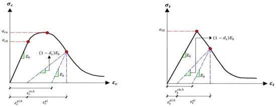
Figure 1.
Response of concrete to uniaxial loading conditions: (Right) Tension, (Left) Compression [9].
As a result, the uniaxial effective tensile and compressive stresses () and () are determined using the following formulas:
The tensile strain is defined as in this context, while the compressive strain is denoted as .
2.2. Analysis of Elastoplastic Limits
The fundamental principle of limit analysis may be illustrated as follows: Examine an elastoplastic body subjected to a continuously increasing force. To formally state the proportional loading, one may use the following: The limit analysis issue is illustrated as follows: Examine an elastoplastic material subjected to a certain force and always augmenting this energy. The proportional loading may be articulated as follows () [30]:
In this context, () is a scalar quantity that increases gradually and is referred to as load amplification, while () denotes the constant initial external force. The plastic deformation zones of the body expand gradually as () increases, ultimately reaching a specific intensity (). During this phase, unrestricted plastic deformation takes place, enabling the continuous expansion of plastic deformations and displacements as a result of external forces during the loading phase. Unrestricted plastic deformation of the entire body or specific sections occurs when an elastoplastic body is subjected to sustained external stress, thereby reaching its plastic limit state. The stress at the elastic limit, (), multiplied by (), is equivalent to the ultimate load during plastic deformation, (). Equilibrium equations are indispensable during the plastic limit phase, as stresses and forces may persist in a state of static equilibrium. Consequently, the body’s ultimate plastic burden is ( = ).
The symbol (k) denotes the material’s plastic properties. The concept of imaginary velocities can be applied to the force and stress fields of a deformable body with volume (V) and loading surface () by incorporating velocities () and kinematically permissible strain rate ()
Subtracting these two equations:
In order to guarantee that all points adhere to the normality criterion and the convexity of the yield surface, all surface points must be normalized, resulting in a normal distribution.
Hence, Equation (15) yields
The integral in this illustration suggests that the body’s actual velocities are influenced by external forces. To prevent negative work, the condition () must remain positive. The outlined steps highlight the enhanced uniqueness and convexity of the procedure. The mathematical complexity of the method does not increase when this element is incorporated into topology design.
3. Objective Functions of Carbon Emissions
This study introduces a sustainable slab design method, which aims to monitor the safety of the concrete slabs by calculating CO2 emissions through an analysis of an elasto-plastic model strengthened with CFRP strips. It compares this technique to a control slab that was not strengthened. The objective functions are defined and analyzed in this study by Equation (18) [30].
In Equation (18), (V) represents the volume and () is the density of the materials, with unit CO2 emissions (E) for concrete (c), steel (s), carbon-fiber-reinforced polymer (CFRP), and the epoxy resin (e). Typical values for the density of concrete are 2300 kg/m3, steel 7850 kg/m3, CFRP is 1500 kg/m3 and for the epoxy resin is 1200 kg/m3. These parameters are used to calculate the CO2 emissions for the structure. Carbon emission factors represent the emissions produced per unit mass of energy resource consumption. The choice of these factors significantly influences the accuracy of carbon emission calculations. However, the values for carbon emission factors can vary for different materials in specific buildings, depending on the measurement method or data source. To ensure precise calculation results in the model, this paper uses the carbon emission factor data presented in Table 1 [31,32].

Table 1.
Carbon dioxide emissions associated with the materials used in 30 MPa grade concrete [31,32].
4. Experimental Work
The efficacy of RC two-way slabs strengthened with CFRPs was assessed through an experimental program. This entailed the construction of four RC slab specimens, all of them subjected to a focused load and supported at the ends. The dimensions of all slabs were (1200 mm × 1200 mm × 130 mm), as demonstrated in Figure 2a. The control specimen was designated as S1, and the other specimens were labeled S2, S3, and S4. Furthermore, laboratory experiments were implemented to evaluate the concrete’s properties.
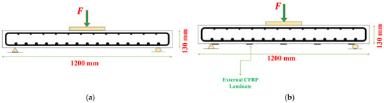
Figure 2.
Design of slab specimens: (a) Slab (S1) without strengthening, (b) reinforced slab with CFRPs.
Concrete with a compressive strength ( of 30 MPa was employed to construct the test specimens as determined by standard cylindrical strength experiments. To evaluate three cylinders and three cubes were used. The tensile and compressive properties of these specimens were evaluated after a curing period of 28 days, resulting in average values. The compressive strength results for both cubes and cylinders are presented in Table 2. The concrete’s compressive and tensile behavior were assessed during the laboratory experiments, as illustrated in Figure 3. In addition, failure of concrete is expected in tension, so the behavior of concrete in tension is very important in terms of calculating the damage within the model, as shown in Figure 3b.
Table 2.
Compressive Strength of Concrete.
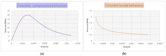
Figure 3.
Experimental Properties of Concrete Under (a) Compression and (b) Tension.
Fifteen steel rods, each with Φ 10 mm that were spaced 61 mm apart center-to-center, represent the tensile reinforcement in all specimens, while the compressive reinforcement included twelve steel bars, each with Φ 6 mm, that were positioned 85 mm apart center-to-center. Detailed information regarding the reinforcements is provided in Table 3.
Table 3.
Reinforcement Bar Properties.
The reinforcement was placed in two layers, following common practice. The design was based on the normal loads of a residential building (excluding parking stories, which have higher live loads). In addition to meeting design requirements, other code stipulations [33] (such as minimum and maximum reinforcement spacing) were also considered to ensure the placement closely mirrored practical applications.
The parametric study focused on the strengthening of slabs using NSM CFRP laminates, where CFRPs were attached to the bottom face of the slabs with epoxy. The mechanical properties of the CFRP and epoxy are detailed in Table 4. For the strengthening of the slabs using CFRP strips, the requirements of the ACI440.2R-17 code were considered [34].
Table 4.
Properties of CFRPs and Epoxy.
The strengthened slab designations were divided into three specimens: Slab S2 was strengthened in both directions with five CFRPs, each strip having a 1.2 mm thickness and a 15 mm width, as shown in Figure 2b. Slab S3 was strengthened in both directions with five CFRPs, each strip having a 30 mm width and a 1.2 mm thickness. In addition, slab S4 was reinforced with five CFRPs in both directions, each strip having a 45 mm width and a 1.2 mm thickness.
This study primarily focused on static loading conditions. This limitation means the findings may not fully predict the behavior of RC structures under dynamic or seismic loads. The numerical model used, while validated against experimental data for static loading, may not accurately simulate the complex behavior of RC structures under dynamic or seismic loading conditions. Factors such as cyclic loading, strain rate effects, and energy dissipation mechanisms in the event of an earthquake are not fully captured. Certain assumptions and simplifications inherent in the numerical model, such as perfect bond conditions between CFRP and concrete, uniform material properties, and ignoring potential degradation of CFRP under cyclic loads, can affect the accuracy of the predictions for real-world applications. Also, this study highlighted an increase in CO2 emissions due to CFRP strengthening, which poses an environmental concern. Balancing the benefits of enhanced structural performance with environmental impact remains a challenge. Engineers must consider the potential discrepancies between the model predictions and actual performance under dynamic loads. Conservative design approaches and additional safety factors may be required until more robust and validated models are developed.
5. The Response of Concrete Slabs and the Test Procedure
At each loading stage, the behavior of the RC two-way slabs was tracked using various instruments. During each loading increment, measurements were taken for parameters including deflection, cracking widths, initial load of cracking, and ultimate load. Testing continued until the slab failed, and the maximal load was recorded. A dial gauge with a precision of 0.01 mm and a load cell with a 700 kN capacity were employed to obtain deflection readings at the center of the slab’s bottom tension face.
The specimens were meticulously arranged into customized frame equipment, irrespective of their weight. An incremental load of 5 kN was implemented; initial dial gauge readings were recorded at zero loading. At each stage, the applied load was increased by 5 kN, and the cracks that developed on the concrete slabs’ surfaces were documented with a pencil. Simultaneously, the dial gauge was used to acquire deflection measurements, while the initial load of cracking was documented at each load increment, and the crack widths were evaluated using steel infill. The technique proceeded with further load phases according to the same methodology until the maximum load was attained and recorded.
The cracking load (), ultimate load (), crack width () at , and central deflections (Δv) at are shown in Table 5. Failure in flexure was intended for the control surface. To be compared:
Table 5.
Experimental Results of Slab Testing.
Control slab (S1): This slab was subjected to flexural testing without the use of any reinforcing techniques, with the objective of achieving failure. The slab’s behavior was attentively monitored as the load progressively increased. The substrate initially demonstrated elastic behavior until the initial damage emerged in the constant moment region at 120 kN. Flexural cracks developed as the load persisted, swiftly widening and extending toward the margins. Slab S1 experienced flexural failure at 241 kN, as demonstrated by a precipitous increase in deflection, whereas the load remained constant.
Strengthened slabs with external CFRPs: The CFRP laminate segments are attached to the slab’s base using epoxy resin as the adhesive in this method. The primary cracking was observed at loads of (190.6, 208.5, and 237.28) kN for slabs (S2, S3, and S4), respectively.
Slab S2, Slab S3, and Slab S4 experienced punching failure at stresses of (455, 498, and 564) kN, respectively. In comparison to slab S1, increased by 88.7% for slab S2, 107% for S3, and 134% for S4. underscoring the substantial effect of augmenting the reinforcement ratio inside CFRPs. With the load remaining constant, deflection escalated swiftly. Augmenting the applied load correspondingly escalates damage severity, signifying that increased load generates greater initial strains in both steel and concrete elements. This highlights the significance of complementary strain energy in depicting plastic degradation. Efficient handling of this component reduces occurrences of plastic degradation and failure.
Table 5 indicates that the use of CFRP laminates to reinforce concrete slabs improves relative to slab S1. The results are also displayed in the form of a column chart in Figure 4. Furthermore, slab S4 had the greatest maximum and the minimum crack width. The data suggest that slabs reinforced with CFRPs had punching failure, while slab S2 collapsed owing to debonding. The results demonstrate the efficiency of CFRPs in the enhancement of the of slabs while simultaneously reducing deflection and the width of cracks under comparable loads.
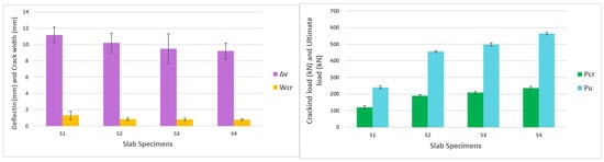
Figure 4.
Experimental Results of Slab Testing: (Left) Deflection and Crack Width, (Right) Cracking Load and Ultimate Load.
6. Numerical Modelling
The nonlinear behavior of RC two-way slabs that strengthened with CFRPs was simulated using finite element (FE) analysis, as illustrated in Figure 5. Concrete was represented within Abaqus CAE® using a damage plasticity model in this study. The modeling procedure involved four simply supported RC two-way slabs: one control slab that was devoid of CFRPs and three slabs that were fortified with CFRPs in varying proportions. The concrete substructure was modeled using 8-node solid elements (C3D8R), while 2-node linear beam elements (T3D2) were used to represent the reinforcement bars.
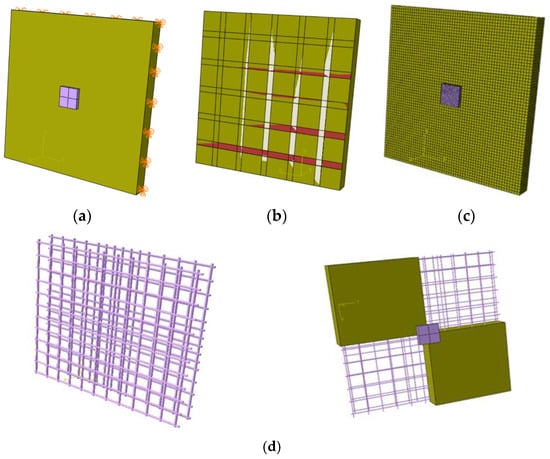
Figure 5.
Details of the numerical model: (a) supporting and loading conditions, (b) strengthening details, (c) details of the mesh, and (d) details of reinforcement.
In accordance with the Abaqus CAE® manual, the bond between CFRP and concrete was modeled as a surface-to-surface contact, and the bond between reinforcements and concrete was simulated using an embedded region. To prevent local failure as a result of compression, steel plates with dimensions of (250 × 250 × 25) mm were positioned and modeled using 8-node solid elements (C3D8R). The boundary conditions were a roller support at one end for horizontal movement and rotation and a pin support for rotation at the other end. A vertical concentrated load was applied to the center of the slab’s external face in order to replicate the experimental conditions. A thin mesh was employed to ensure precision, resulting in approximately 21,600 slab elements. The assessment of the influence of various mesh sizes on numerical clarity and computational efficiency revealed that the highest level of accuracy was attained with a mesh size of 20.
The validation procedure employed 3D finite element models in Abaqus CAE® using a CDP model. Four two-way slabs with simple support were employed to validate the experimental results. The concrete damage plasticity dataset, which is derived from mechanical property experiments on specimens, acknowledges both compressive compression and tensile fracture as failure mechanisms. By incorporating those features into Abaqus CAE®, the determination of CDP parameters is facilitated, thus guaranteeing a precise estimation of the damage behavior of concrete. The CDP parameters are determined by utilizing the data presented in Table 6 following sensitivity analyses. Nevertheless, these CDP parameters remain consistent in subsequent optimization iterations. The numerical model is depicted in Figure 5.
Table 6.
Input data for concrete from the CDP.
The comparable outcomes are illustrated in Figure 6, which illustrates the combined outcomes of numerical and experimental methodologies. Furthermore, Figure 7 illustrates similar tension damage patterns, showing a significant reduction in damaged red areas in the flexural regions of the slabs when CFRP is applied. The force–deflection curve compares four different concrete slabs. Among these, three slabs (S2, S3, and S4) are strengthened with CFRP strips, resulting in significantly improved performance. S1 (Control Slab), the unstrengthened slab, has the lowest force capacity, peaking at around 200 KN at approximately 6 mm deflection, while S4, the most enhanced slab with CFRP, achieved the highest force capacity, peaking at around 550 KN at about 8 mm deflection. Therefore, the curves illustrate that CFRP strengthening significantly enhances the load-bearing capacity and stiffness of the concrete slabs, with S4 showing the most substantial improvement. The numerical results closely follow the experimental data, validating the predictive models used. The comparison between the images of experimental tests and the corresponding finite element model highlights the effectiveness of CFRP strips in reducing damage: The unstrengthened slab shows extensive cracking, with high stress concentrations, particularly in the flexural regions, while the strengthened slabs show reduced cracking. The extent of the red areas is significantly diminished, indicating improved structural integrity and reduced tension damage. Therefore, the comparison illustrates that applying CFRP strips to the two-way slabs enhances their performance by mitigating damage and reducing stress concentrations, thereby increasing their load-bearing capacity and overall durability. The experimental results align well with the numerical simulations, validating the effectiveness of CFRP reinforcement in practical applications.
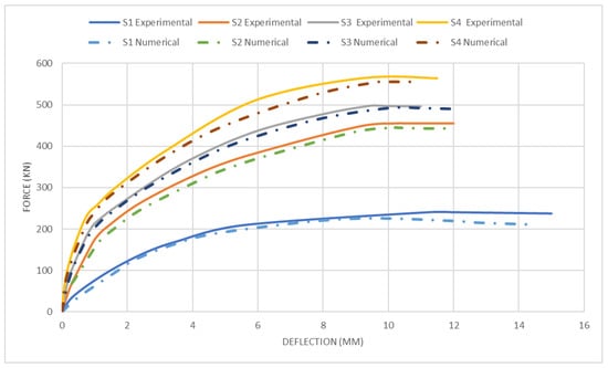
Figure 6.
Experimental and numerical load–deflection relationships for all four models.
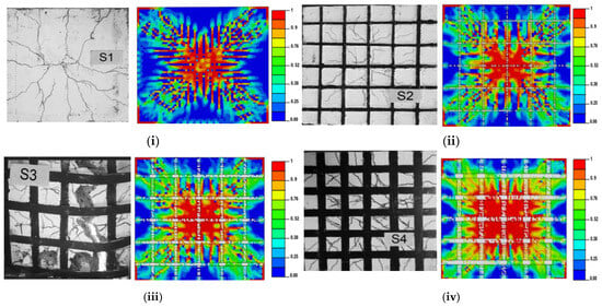
Figure 7.
Numerical and experimental comparison of damage patterns: (i) Slab S1, (ii) Slab S2, (iii) Slab S3, and (iv) Slab S4.
Table 7 presents the total amount of CO2 by applying the carbon dioxide emission factor (kg-CO2/kg) from Table 1 and the weight of each material in Equation (19).
Table 7.
Total carbon emissions (kgCO2e/kg).
The minimum amount of carbon emission (kg) from slab S1 is equal to 107.23 kg, while slab S4 has the highest amount of CO2 emission at 123.82 kg, as it has the largest CFRP covering. This shows that the use of CFRP strips will increase CO2 emissions by a small percentage.
Also, the relationship between the percentage of damage and the load multiplier for all fourth slab specimens is depicted in Figure 8. It can be noticed that at the lower load, slab S4 had the lowest percentage of damage in comparison with the control slab. By increasing the load multiplier, the percentage of damage will increase, but the existence of the CFRP strips minimizes the amount of damage at the same stage of the applied load in comparison with the three strengthened concrete slabs. In addition, increasing the area of strengthening will decrease the amount of damage at the same applied load. The damage intensity increases as the load increases, indicating that concrete, CFRPs, and steel materials are subjected to additional stress. In addition, at the same load multiplier, the percentage of damage will decrease while the CO2 emissions will increase but by a small percentage in the slabs (S2, S3, and S4), which are strengthened with CFRP in comparison with the control slab S1 which was without any strengthening. This emphasizes the significance of integrating complementary strain energy to accurately represent plastic injury. Plastic damage and defects are reduced through the effective management of this factor.
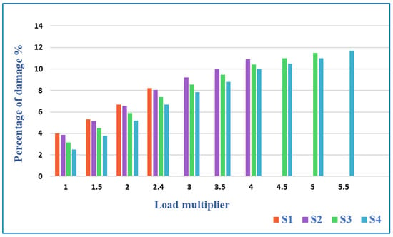
Figure 8.
Comparison of Damage Percentage of Control Slab and Strengthened Slabs.
The use of CFRP led to strengthened concrete slabs without a clear increase in carbon emissions compared to non-reinforced slabs. As well as CFRP, having higher initial energy consumption during production, offers significant long-term environmental benefits due to its lightweight nature and durability, which reduces the overall material usage and associated emissions over the lifecycle of the structure. Additionally, innovative recycling processes for CFRP, such as chemical recycling, further enhance its sustainability by reducing waste and energy consumption compared to traditional materials.
7. Conclusions
This study investigated the elastoplastic numerical modeling of RC slabs that were fortified with CFRPs. To accurately depict the behavior of concrete and the emission of CO2, the numerical model was validated using the concrete damage plasticity (CDP) constitutive model in Abaqus CAE® and the experimental data.
The effectiveness of the RC slab specimens was significantly influenced by the fortification ratios, as an increase in the fortifying percentage consistently led to a higher ultimate strength. Slabs S2, S3, and S4, when strengthened with CFRP, showed reduced cracking width, increased cracking load, and increased ultimate strength. The increase in ultimate loads happened with percentages of 88.7%, 107%, and 134% for Slabs S2, S3, and S4, respectively, compared to slab S1.
The damage pattern data indicated that concrete damage due to tension increased proportionally with load, signifying that higher load induced initial stresses in steel reinforcement and concrete. The complementary energy strain played a crucial role in reflecting plastic damage, with its proper management helping to prevent failure and excessive plastic damage.
Applying elasto-plastic analysis provided insight into the safety of the structure by assessing the percentage of damage at each load stage. Additionally, expanding the strengthening area increased CO2 emissions, although only slightly compared to the control slab S1 by the percentages of 5% for slab S2, 10% for slab S3, and 15% for slab S4.
Notably, a reduction in CFRP strips tended to expand red areas, indicating potential damage to steel or concrete. Conversely, using more CFRP strips reduced these red zones, mirroring the effects observed with lower reinforcement ratios. Structures with less reinforcement and under lighter loads endured higher stress, potentially leading to failure at reduced loads.
Author Contributions
Methodology, M.M.R. and R.C.; writing—original draft preparation, Z.S.S.; conceptualization, Z.S.S., M.D. and R.C.; formal analysis, Z.S.S.; resources, M.M.R.; writing—review and editing, M.M.R., R.C., M.D. and O.G.; software, Z.S.S. and O.G.; visualization, Z.S.S. and O.G.; investigation, Z.S.S., M.D. and R.C.; validation, Z.S.S. and O.G.; supervision, M.M.R. and M.D. All authors have read and agreed to the published version of the manuscript.
Funding
This research received no external funding.
Data Availability Statement
The data presented in this study are available upon corroborated request from the corresponding author.
Conflicts of Interest
The authors declare no conflicts of interest.
References
- Ojaimi, M.F.; Alabdulhady, M.Y.; Naser, K.Z. Influence of Concrete Compressive Strength on CFRP Strengthening and Repairing of RC Two-Way Slabs. J. Eng. 2024, 2024, 2166919. [Google Scholar] [CrossRef]
- Sahranavard, S.; Jahangir, H.; Kazemi, H.H. An experimental and numerical investigation of RC slabs externally strengthened by perforated steel plates. Structures 2022, 45, 1239–1252. [Google Scholar] [CrossRef]
- Shafaie, V.; Ghodousian, O.; Ghodousian, A.; Cucuzza, R.; Movahedi Rad, M. Integrating push-out test validation and fuzzy logic for bond strength study of fiber-reinforced self-compacting concrete. Constr. Build. Mater. 2024, 425, 136062. [Google Scholar] [CrossRef]
- Olivo, J.; Cucuzza, R.; Bertagnoli, G.; Domaneschi, M. Optimal design of steel exoskeleton for the retrofitting of RC buildings via genetic algorithm. Comput. Struct. 2024, 299, 107396. [Google Scholar] [CrossRef]
- Wang, Y.D.; Yang, S.; Han, M.; Yang, X. Experimental study of section enlargement with reinforced concrete to increase shear capacity for damaged reinforced concrete beams. Appl. Mech. Mater. 2012, 256–259, 1148–1153. [Google Scholar]
- Ebead, U.; Marzouk, H. Strengthening of two-way slabs using steel plates. Struct. J. 2002, 99, 23–31. [Google Scholar]
- Banu, D.; Taranu, N. Traditional solutions for strengthening reinforced concrete slabs. Inst. Politeh. Din Lasi Sect. Constr. Arhit. 2010, 56, 53. [Google Scholar]
- Mercimek, Ö.; Ghoroubi, R.; Anil, Ö.; Çakmak, C.; Özdemir, A.; Kopraman, Y. Strength, ductility, and energy dissipation capacity of RC column strengthened with CFRP strip under axial load. Mech. Based Des. Struct. Mach. 2023, 51, 961–979. [Google Scholar] [CrossRef]
- Ghoroubi, R.; Mercimek, O.; Ozdemir, A.; Anil, O. Experimental investigation of damaged square short RC columns with low slenderness retroftted by CFRP strips under axial load. Structures 2020, 28, 170–180. [Google Scholar] [CrossRef]
- Sharhan, Z.S.; Movahedi Rad, M. Elasto-Plastic Analysis of Two-Way Reinforced Concrete Slabs Strengthened with Carbon Fiber Reinforced Polymer Laminates. Computation 2024, 12, 93. [Google Scholar] [CrossRef]
- Abbood, I.S.; aldeen Odaa, S.; Hasan, K.F.; Jasim, M.A. Properties evaluation of fiber reinforced polymers and their constituent materials used in structures—A review. Mater. Today Proc. 2021, 43, 1003–1008. [Google Scholar] [CrossRef]
- Limam, O.; Foret, G.; Ehrlacher, A. RC two-way slabs strengthened with CFRP strips: Experimental study and a limit analysis approach. Compos. Struct. 2003, 60, 467–471. [Google Scholar] [CrossRef]
- Mosallam, A.S.; Mosalam, K.M. Strengthening of twoway concrete slabs with FRP composite laminates. Constr. Build. Mater. 2003, 17, 43–54. [Google Scholar] [CrossRef]
- Ebead, U.; Marzouk, H. Fiber-reinforced polymer strengthening of two-way slabs. Struct. J. 2004, 101, 650–659. [Google Scholar]
- Chen, Z.; Wan, L.; Lee, S.; Ng, M.; Tang, J.; Liu, M.; Lee, L. Evaluation of CFRP, GFRP and BFRP material systems for the strengthening of RC slabs. J. Reinf. Plast. Compos. 2008, 27, 1233–1243. [Google Scholar] [CrossRef]
- Yılmaz, T.; Kıraç, N.; Anil, O.; Erdem, R.T.; Sezer, C. Low-velocity impact behaviour of two way RC slab strengthening with CFRP strips. Constr. Build. Mater. 2018, 186, 1046–1063. [Google Scholar] [CrossRef]
- Al-Rousan, R.; Issa, M.; Shabila, H. Performance of reinforced concrete slabs strengthened with diferent types and confgurations of CFRP. Compos. Part B Eng. 2012, 43, 510–521. [Google Scholar] [CrossRef]
- Dániel, H.; Habashneh, M.; Rad, M.M. Reliability-based numerical analysis of glulam beams reinforced by CFRP plate. Sci. Rep. 2022, 12, 13587. [Google Scholar] [CrossRef]
- Grubits, P.; Cucuzza, R.; Habashneh, M.; Domaneschi, M.; Aela, P.; Rad, M.M. Structural topology optimization for plastic-limit behavior of I-beams, considering various beam-column connections. Mech. Based Des. Struct. Mach. 2024, 1–25. [Google Scholar] [CrossRef]
- Rad, M.M.; Ibrahim, S.K.; Lógó, J. Limit design of reinforced concrete haunched beams by the control of the residual plastic deformation. Structures 2022, 39, 987–996. [Google Scholar]
- Carol, I.; Rizzi, E.; Willam, K. On the formulation of anisotropic elastic degradation. I. Theory based on a pseudo-logarithmic damage tensor rate. Int. J. Solids Struct. 2001, 38, 491–518. [Google Scholar] [CrossRef]
- Krätzig, W.B.; Pölling, R. An elasto-plastic damage model for reinforced concrete with minimum number of material parameters. Comput. Struct. 2004, 82, 1201–1215. [Google Scholar] [CrossRef]
- Gatuingt, F.; Pijaudier-Cabot, G. Coupled damage and plasticity modelling in transient dynamic analysis of concrete. Int. J. Numer. Anal. Methods Geomech. 2002, 26, 1–24. [Google Scholar] [CrossRef]
- Lubliner, J.; Oliver, J.; Oller, S.; Onate, E. A plastic-damage model for concrete. Int. J. Solids Struct. 1989, 25, 299–326. [Google Scholar] [CrossRef]
- Ananiev, S.; Ozbolt, J. Plastic–damage model for concrete in principal directions. In Fracture Mechanics of Concrete Structures; Li, V., Leung, C.K.Y., William, K.J., Billington, S.L., Eds.; Cornell University: Ithaca, NY, USA, 2004; pp. 271–278. [Google Scholar]
- Imran, I.; Pantazopoulou, S.J. Plasticity model for concrete under triaxial compression. J. Eng. Mech. 2001, 127, 281–290. [Google Scholar] [CrossRef]
- Oh, B.K.; Glisic, B.; Lee, S.H.; Cho, T.; Park, H.S. Comprehensive investigation of embodied carbon emissions, costs, design parameters, and serviceability in optimum green construction of two-way slabs in buildings. J. Clean. Prod. 2019, 222, 111–128. [Google Scholar] [CrossRef]
- Ke, L.; Li, Y.; Li, C.; Cheng, Z.; Ma, K.; Zeng, J. Bond behavior of CFRP-strengthened steel structures and its environmental influence factors: A critical review. Sustain. Struct. 2024, 4, 000038. [Google Scholar] [CrossRef]
- Broyles, J.M.; Gevaudan, J.P.; Hopper, M.W.; Solnosky, R.L.; Brown, N.C. Equations for early-stage design embodied carbon estimation for concrete floors of varying loading and strength. Eng. Struct. 2024, 301, 117369. [Google Scholar] [CrossRef]
- Rad, M.M.; Papp, F.; Ibrahim, S.K.; Szép, J.; Gosztola, D.; Harrach, D. Elasto-plastic analysis and optimal design of composite integral abutment bridge extended with limited residual plastic deformation. Sci. Rep. 2023, 13, 5461. [Google Scholar] [CrossRef]
- Kaveh, A.; Izadifard, R.A.; Mottaghi, L. Optimal design of planar RC frames considering CO2 emissions using ECBO, EVPS and PSO metaheuristic algorithms. J. Build. Eng. 2020, 28, 101014. [Google Scholar] [CrossRef]
- Stoiber, N.; Hammerl, M.; Kromoser, B. Cradle-to-gate life cycle assessment of CFRP reinforcement for concrete structures: Calculation basis and exemplary application. J. Clean. Prod. 2021, 280, 124300. [Google Scholar] [CrossRef]
- ACI 318-19; Building Code Requirements for Structural Concrete. American Concrete Institute: Farmington Hills, MI, USA, 2019.
- ACI 440.2R-17; Guide for the Design and Construction of Externally Bonded FRP Systems for Strengthening Concrete Structures. American Concrete Institute: Farmington Hills, MI, USA, 2017.
Disclaimer/Publisher’s Note: The statements, opinions and data contained in all publications are solely those of the individual author(s) and contributor(s) and not of MDPI and/or the editor(s). MDPI and/or the editor(s) disclaim responsibility for any injury to people or property resulting from any ideas, methods, instructions or products referred to in the content. |
© 2024 by the authors. Licensee MDPI, Basel, Switzerland. This article is an open access article distributed under the terms and conditions of the Creative Commons Attribution (CC BY) license (https://creativecommons.org/licenses/by/4.0/).