Abstract
The field of 3D printing is in rapid evolution. The 3D printing technology applied to civil engineering is a promising advancement. From equipment and mixture design to testing methods, new developments are popping up to respond to specific demands either for the fresh or hardened state. Standardizing methods are still at an early age. For this reason, there is a multitude of 3D printers with different capabilities to print cementitious materials. In addition, norms are not applicable in 3D printing material science. Advances are being made to create new methods of testing. The key parameters of this new 3D printing process based on stratification, multiple uses of binders, and measurement at fresh and hardened states are being perfected to achieve an industrial application. This article gives an overview of how 3D-printed structures are made along with critical parameters that influence their performances. Our review suggests that the quality of the 3D prints is determined by the printing method, key printing parameters, and the mix design. We list different tests to help characterize these 3D-printed cementitious materials at the fresh state and to assess their performances at the hardened state. We aim throughout this work to give a state-of-the-art of recent advances in 3D printing technology. This could help for a better understanding of cementitious materials 3D printing for current and future related research work.
Keywords:
3D printing; 3D printer; cementitious materials; mix design; fresh state; hardened state; durability 1. Introduction
Three-dimensional printing is a growing process used in industries to develop custom parts, prototypes, or parts in small series [1].
In the field of construction, especially in concrete technologies, the advantages of 3D printing compared to traditional casting appear interesting and promising.
First, 3D printing allows the reduction of waste and consequently the corresponding environmental impact. This is possible with the use of the exact quantity of materials. Moreover, a decrease in construction costs could be possible by eliminating formwork and a decrease in labor time. With 3D modeling, architectural freedom is promoted by being able to offer more complex geometries. This automation allows increased safety by reducing work accidents and creating more qualified jobs [1,2].
The reduction of construction time is also possible by promoting an on-site construction and continuous operation of the 3D printer [1,2,3].
Industries have advanced far in the field of 3D printing; for example, XtreeE uses a CAD model for a 3D-printed high-performance concrete multifunctional wall [4]. In some instances, XtreeE was able to 3D print a prototype of an artificial reef, and the objective here is to produce this prototype on an industrial scale for marine restoration [5]. In another industry, Saint-Gobain Weber Beamix 3D printed a 29 m long bridge for cyclists, which uses several BAM robotic arms. The bridge is designed with round and natural shapes to blend in with its outdoor placement [6]. The prowess that can be achieved on an industrial scale seems to be limitless.
Although there are several review publications regarding the mix proportion of 3D printing of cementitious materials and other related subjects [7,8,9], this work focuses mainly on key printing parameters and characterization, which have rapidly advanced during the last few years. Thus, we consider that a review containing mainly these two subjects is needed for the scientific community.
To operate 3D printing adequately in the field of construction, the materials must meet printability criteria. Meeting these criteria is necessary to obtain final conforming properties. The multitude of 3D printing apparatuses, types of cementitious materials, and tests result in lack of harmonized studies. This review paper aims to list the different ways 3D printing of cementitious materials is possible, the parameters influencing the quality of the prints, and finally the useful techniques to characterize the pre-printed and printed structures with respect to physical, mechanical, and durability properties.
2. Type of Printers: 3D Printing Technology
Three-dimensional printing is an additive manufacturing process as opposed to casting and subtractive manufacturing [10]. Casting is a shaping technique that uses a temporary mold or formwork where the mixture is poured to obtain the desired shape. The final object is obtained by removing the mold or formwork after hardening of the mixture. Subtractive manufacturing is the process of obtaining the object by removing material from a block.
The object to be printed is modeled in 3D on Computer-Aided Design (CAD) software. The 3D model is converted to a “.stl” file (.stl stands for stereolithography) so that the design can be translated into a horizontal layer of information. Using adequate software, the layer size, speed, filling, and other parameters are determined and coded into a “.gcode” program. This type of file is processed by most 3D printing machines using Fused Deposition Modeling (FDM) and stereolithography. The printer is then set up to adjust the parameters according to the specificities of the machine (x, y, z position, material flow, printing speed, etc.) [11,12]. After the building stage, a cleaning or post-treatment stage could be needed.
The different 3D printing technologies are subdivided into seven categories (see Figure 1):
- Category 1: Material extrusion is also known as robocasting and FDM. Robocasting is the deposition of a liquid or pasty mixture that hardens to support the structure. The concrete or mortar hardening is a combination of chemical reactions followed depending on external conditions by evaporation. FDM is based on the extrusion of molten filaments, often plastic or composite. The molten filament is deposited by the nozzle of the machine. Its final shape is retained by cooling the filament.
- Category 2: Photopolymerization uses the solidification of light-sensitive polymers under the action of a laser or light source; these devices are called stereolithography (SLA) and digital light processing (DLP).
- Category 3: The deposition of materials in drop form and treated to be solidified (material jetting).
- Category 4: The jet of liquid binder on a bed of powder (binder jetting).
- Category 5: Solidification of a bed of material using a laser or electron gun powder bed fusion (selective laser sintering, SLS).
- Category 6: The addition of material melted by a laser and simultaneously deposited by a nozzle (direct energy deposition).
- Category 7: The layering of cut sheets and fixing together sheet lamination (laminated object manufacturing, LOM, and ultrasound additive manufacturing, UAM) [13,14].
In general, for cementitious materials, the printing technologies used are particularly based on extrusions. Indeed, the hydration reactions of the cement allow the hardening of the paste, which is necessary for printing by this method [15]. Moreover, the rheology of the mixture must be controlled to pass through the printer system in a fluid state. Then, the mixture must retain its shape during filament extrusions. Also, the mechanical strength of the mixture obtained through the hydration of cement must reach adequate value to support the above 3D-printed structure [16]. Finally, a defect-free hardened structure must be obtained with similar properties to obtain a conventionally manufactured object.

Figure 1.
Seven different 3D printing methods showing the schemes and the corresponding process [13,17].
Figure 1.
Seven different 3D printing methods showing the schemes and the corresponding process [13,17].

2.1. Extrusion Type Printing
2.1.1. Variation of the Technology
The extrusion method applied to 3D printing involves transporting the fluid mixture from the containing chamber to the print head. The material is deposited at the desired location. The following layers are deposited to create a 3D-printed structure [18,19]. The sections of the extrusion 3D printer consist of a supply section, a movement activation section, and a mixture transport section. There are several types of extrusion 3D printers, defined by their automation solution. The automation could either be supported by a robotic arm, by a gantry also known in the literature as a Cartesian structure, or by a structure called “Delta robot” [20].
Three-dimensional printers with a robotic arm (Figure 2a) are machines that control the print head along several axes of rotation using an articulated arm [4]. The advantage, unlike other types of 3D printer, is the absence of printing plates.
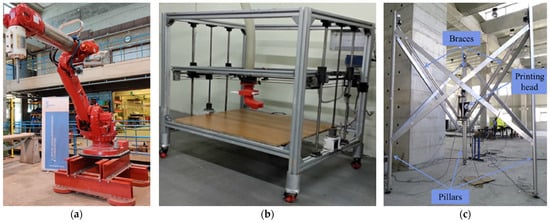
Figure 2.
Different types of 3D printers. (a) Six-axis industrial robot for 3D printing for extrusion method [21]. (b) Laboratory gantry 3D printer for extrusion method [22]. (c) Delta robot used for 3D printing for extrusion method [20].
Cartesian gantry printers consist of an arch that allows the translation of the printer head along the axes, with four degrees of freedom, over a print flat plate (Figure 2b). In some cases the print plate can be moved in height along the z-axis or in rotation [23].
The Delta structure is used on the BigDelta WASP printer (Figure 2c) [13]. The structure consists of three pillars. The arms attached to these pillars hold the 3D print head above the triangular print area. The printing area is therefore limited in space and difficult to move.
Laboratory printers are limited by the maximum size of the 3D-printed object. However, this makes it easy to test shapes and mixtures [22]. These printers are also used to manufacture parts or modular elements to obtain a complex object, such as bridges for example [20,24].
The same printer models are available in larger sizes for large-scale construction. Some of them are mounted on tracks or controlled with a crane to best suit on-site production [13]. Another promising technology with a robot was developed to allow mobility during 3D printing. This could possibly open new possibilities to print larger structure [25,26].
Three-dimensional-printed structures are often designed to be directly used for their construction function, but another approach (see Figure 3) is to print a 3D mold. With this process, the mold is designed with a different type of material and then removed. However, an approach using molds printed in the same material exists. The mold is then kept [27]. This approach makes it possible to have the final object directly.
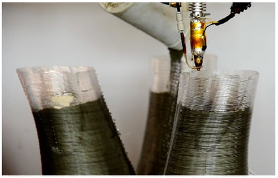
Figure 3.
Simultaneous concrete filling and formwork printing process; a thermoplastic polymer is extruded and moved according to a defined geometry to build the formwork, while set-on-demand concrete is filled in it (adapted from [27]).
2.1.2. Mixing
The mixing method determines the fresh state behavior of the mixture, which then needs to be adapted through the selection of its components.
A first existing method is to mix using a mixer separated from the printer. In this case, the mixture is homogenized before printing. The volume of material must therefore be adapted to be able to print without interruption, mainly to avoid fresh state property variation over time due to cement hydration. The time windows must be estimated and adjusted to prevent the hardening of the mixture inside the 3D printer system. Often, the printed objects with this method are limited in size [4].
A second existing method is to mix continuously. In this way, the construction is not limited to the size of the mixer or the tank and the material is always renewed (Figure 4) [28].
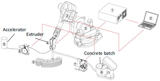
Figure 4.
Mixing and pumping systems for a robot printer, 0. System command; 1. Robot controller; 2. Printing controller; 3. Robotic arm; 4. Printhead; 5. Accelerating agent; 6. Peristaltic pump for accelering agent; 7. Peristaltic pump for premix; 8. Premix mixer; 9. 3D printed object [4,28].
A final existing method is to adapt the fresh state properties of the mixture during the printing process with the progressive incorporation of additives. The behavior is then tailor-made according to the prescription. However, the mixture in this case is difficult to homogenize due to the addition of a setting accelerator in the 3D printer head [13,28].
2.1.3. Pumping System
The pumping system is the main system for setting the mixture in motion. It is necessary to adapt the pumping characteristics in order to properly control the extrusion of a given mixture. The pumping system can either be a piston system or a peristaltic one [9]. The pump can also be accompanied by an additional system to assist the extrusion process. This is usually performed with the help of an adequate endless screw system or an additional vibration system [19].
2.1.4. The Nozzle
The nozzle is connected to the 3D printer head and is used for shaping the deposit. The shape and size of the nozzle define the correct shaping of the printed lines. Nozzle diameter, visible for example in Figure 5, allows control of the shape but can also influence other parameters like flow, print speed, accuracy of printing, and, if necessary, the fiber’s orientation [29]. Usual nozzles for cementitious materials are rectangular, circular, or elliptical in shape and with sizes from millimeters to centimeters. It is important to adapt nozzle size to the largest elements of the mixture (Table 1) [30]. Other non-conventional designs of nozzles achieved optimal interlayer bonding and reliable shape stability. A better control of 3D printing parameters related to nozzles have been shown to allow a better interconnection of printed layers [26,31,32,33].
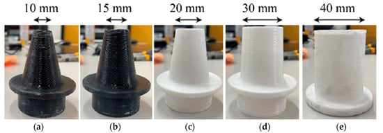
Figure 5.
Nozzle with diameters of (a) 10 mm, (b) 15 mm, (c) 20 mm, (d) 30 mm, and (e) 40 mm [29].
Additional elements can be adapted on the nozzle to improve the adhesion of the lines or for esthetic purposes of the part. Some of these elements are vibration devices, adhesion aid layers, reinforcement grids, or smoothing scrapers for contour crafting [19,34,35].

Table 1.
Nozzle size and shape with maximum aggregate size.
Table 1.
Nozzle size and shape with maximum aggregate size.
| Paper | Nozzle Shape | Nozzle Size | Maximum Aggregate Size |
|---|---|---|---|
| Le [36,37] | Circular | 9 mm | 2 mm |
| Nerella [38] | Circular | 40 mm | 2 mm |
| Paul [39] | Rectangular/Circular | 10 × 20 mm and 8 mm | 1 mm |
| Wolfs [40] | Rectangular | 50 × 9.5 mm | 1 mm |
| Panda [41] | Circular | 10 mm | 0.2 mm |
| Rahul [42] | Rectangular | 30 × 30 mm | 1 mm |
| Marchment [43] | Rectangular | 30 × 17 mm | 1 mm |
| Panda [44] | Rectangular | 30 × 15 mm and 20 × 20 mm | 1.15 mm |
| Asprone [20] | Circular | 25 mm | 4 mm |
| Panda [45] | Rectangular | 40 × 10 mm | 1.18 mm |
| Kazemian [46] | Rectangular | 38.1 × 25.4 mm | 2.36 mm |
| Zhang [47] | Circular | 20 mm | 1 mm |
2.2. Other Technologies
Three-dimensional printing of cementitious materials is not limited to the extrusion printing method. Other possible technologies are also being investigated in the literature.
One of the investigated technologies, the Shortcrete 3D printing process, is based on the principle of material jetting (Figure 6). The process involves spraying the mixture in drops to form layers. This type of printing is very similar to extrusion printing, but the nozzle is longer and/or more flexible with compressed air assistance. The formed layers are not well defined but result in a more homogeneous construction.
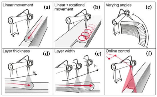
Figure 6.
Specific deposition methods of the Shortcrete 3D printing process (SC3DP): (a) layer-by-layer deposition, (b) laminar application, (c) variation of application angle, (d) control of layer thickness by robot speed (V), (e) control of layer width by nozzle distance (h), (f) line laser for in situ measurement of layer distance and width [48].
Binder jetting or D-shape for concrete is 3D printed on a bed of cement and aggregates with a water drop projection. This technology does not create a layer like extrusion. The 3D structure is created by an agglomeration of material in specific coordinates. However, non-agglomerated material is used to support this type of structure where the non-agglomerated residue must be removed from the base structure. For example, Cesaretti et al. (2014) use this technology with lunar soil to assess the possibility to print on the moon [49]. Alternatively, a concrete or binder mixture can be sprayed onto an aggregate bed (Figure 7) [50].
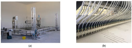
Figure 7.
D-shape 3D printer using a multiple nozzle to ensure a quick print. (a) The structure of the 3D printer; (b) all the nozzles for spraying the binding mixture [50].
Form filling is the custom fabrication of a mold by CAD technology. Some are cut in polymers and wood [51] or 3D printed with polymers or concrete [27,52,53]. The mold is filled with concrete to ensure good mechanical support of the functional part [4,34].
Smart Dynamic Casting (SDC) is the vertical extrusion of concrete, often used for column models [54], as shown in Figure 8. This method of printing uses a fresh mixture into the upper part of the 3D printer, which is relatively smaller than the final printed object. The mixture emerges from the bottom in a partially hardened state due to a waiting period. And with enough strength, it can support the weight of the structure. Yet, the mixture remains fluid enough to be shaped into the formwork. However, the geometry is limited to a variation of rotating or curved structures [27].
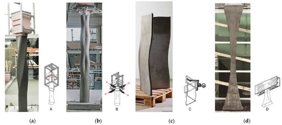
Figure 8.
Smart Dynamic Casting (SDC) with different formwork; (a) rigid formwork; (b) flexible formwork; (c) formwork for thin folded structures; (d) deformed formwork for a varying cross-section [27].
Injection 3D concrete printing is a technique consisting of injecting concrete into a gel (Figure 9), which carries the mixture to the printing bed. This technique allows more freedom of the printed shape compared to other techniques. However, this technique is up to now limited to laboratory uses [55].
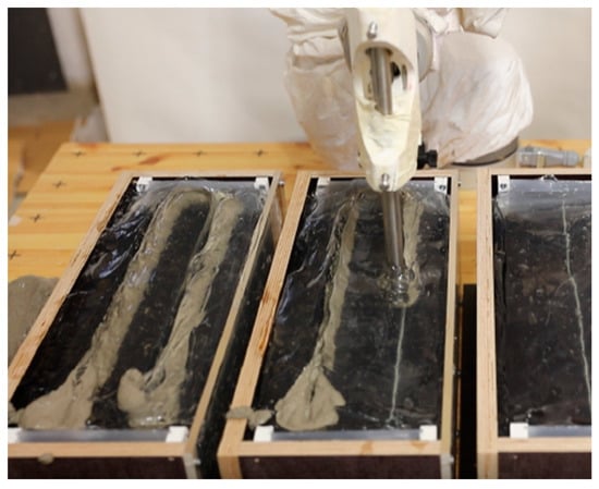
Figure 9.
Injection 3D concrete printing with a nozzle of 18 mm [55].
Table 2 highlights the points of divergence of the different 3D printing technologies for cementitious materials.
Table 2.
Comparison of 3D printing technology.
Another investigated technology involves the incorporation of an adherence layer deposition between the usual layers; the additional layer can be made of additives, different materials, or application of a patterned roll. Van der Putten et al. (2019) compare different interlayer gap times and different properties [56]. Mostert and Kruger (2022) use different patterns and show the improvement in mechanical strength with the interlayer pattern [26,32,33].
2.3. Reinforcements
Reinforcements are used to increase some properties of the resulting 3D printed structures. The reinforcements used in 3D printing need to be adapted to the process. Thus, several solutions have been studied to integrate reinforcements into the 3D printed structure [57].
The reinforcements are classified either from type or the introduction stage during the 3D printing process [58]. We use this latter classification here.
2.3.1. Pre-Incorporated Reinforcements (Either Fibers or Bars)
The first possibility of reinforcement is to add fibers in the formulation used to print (Figure 10). The material in this case is known as a Printable Fiber Reinforced Concrete (Printable FRC) [23,57]. The fibers can be of different origins, such as natural flax and sisal [59,60,61,62], steel [23,29], basalt [23,63], glass [23,39], carbon [23], or polymer like polypropylene fibers [22,36,37,40,42,46,48,64,65]. This technique does not require any modification of the printers, except when fibers are added just before the extrusion stage [58]. One thing to do is to ensure that the fibers do not get tangled at the nozzle. Usually, a homogeneous distribution and a random orientation of the fibers would be preferred to obtain optimized isotropic mechanical properties. However, fibers subjected to a laminar concrete flux and passing through the nozzle tend to align due to radial concrete speed differences, resulting in fibers’ preferred orientation. Depending on the targeted functionality of the printed concrete, this can be either detrimental or not [45]. If the printed object must support anisotropic solicitations, some fibers orientations might be desired. However, for other types of materials such as polymers and composites, a progressive collapse behavior of 3D printed thin-walled under multi-conditional loading can be observed [66].
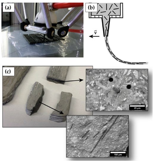
Figure 10.
Fiber-reinforced Portland cement paste. (a) Photograph of 3D printing of a beam specimen; (b) schematic of fiber alignment during 3D printing process; (c) photograph of a sample containing fibers [23].
Another reinforcement strategy is to make a 3D support framework and then spray concrete onto it. Mesh mold technology is one application where a robot welds steel bars to form the 3D framework [51,57,67]. On the same principle, the preinstalled reinforcement method is a method that uses a 3D printer to spray the mixture around a reinforcement grid [43].
As presented earlier, Slipforming is the vertical printing of self-supporting concrete, also known as Smart Dynamic Casting. Reinforcements are used with this technology, and the grid is laid before printing and the concrete is deposited around it [51,57,68].
2.3.2. On-Line Reinforcement Incorporation (Cables and Meshes)
The second reinforcement system is to insert during the printing process. In this case, 3D printers can be modified to allow the correct placement of the reinforcement.
In Figure 11, 3D concrete printing (3DCP) with a reinforcement cable is a system in which the printer continuously adds a reinforcement cable during printing. The cable is injected using the same nozzle as the concrete. The printing has to be adapted because the cable affects section size, print speed, and pump pressure [24,57,69].
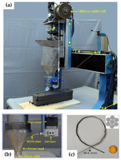
Figure 11.
Set up for micro cable; (a) 3D printer configuration; (b) micro-cable setup; (c) micro cable photograph [69].
In Figure 12, the mesh reinforcing method for 3DCP is a system for adding a reinforcing grid to the 3D printer in parallel with the printing process. This system can link the layers using the mesh [43].
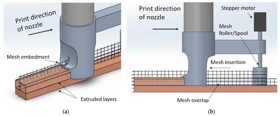
Figure 12.
Mesh insertion in the extrusion process with a custom nozzle; (a) printing view; (b) side view [43].
In another case, 3D-printed concrete formwork corresponds to the addition of reinforcement bars manually or automatically in parallel with the printing process. There are different types of reinforcement: bars, nails, or screws [70]. Several strategies are used to add the reinforcements: addition of bars in the same printing direction, perpendicular to the layers, or with an angle to the printing direction [18,57,68].
2.3.3. Post-Processing Reinforcement
A last type of reinforcement method exists in the literature, consisting of adding the reinforcement material after printing on the outside of the printed elements (Figure 13). The techniques most often used are external reinforcement arrangement [57] or prestressed external reinforcement [57,68] with constrained reinforcements on the outside of several printed elements. This technology is composed of two stages: printing and strengthening the 3D-printed structure.
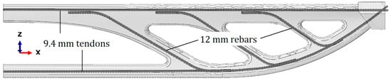
Figure 13.
Post-tensioned reinforcement on 3D-printed concrete bridge (adapted from [71]).
2.4. Support
Support helps to make more flexible structures. The layer-by-layer manufacturing principle imposes not to deposit a top layer on the void. But in order to create openings such as windows and doors, a supporting piece can be added. Usually, a piece of wood is used to support further depositions. The supports evolve and become more complex according to the complexity of the forms. In complex cases, materials support can be printed directly with the 3D-printed part. Another approach used by Kovaleva et al. (2022) [26,72] and Roussel and Lowke (2022) [73] is to print the support material with the same printer but with a second printhead. Another support technology is used by Tay et al. (2019) [74], which consists of printing the support with the same material as the printed object. In this latter case, the support is created with an under-extrusion material, and the excess material is removed after hardening, the authors further highlighting the ability of a structure to support with primary material. This idea is developed by Carneau et al. (2020) [75], with layers inclined in a masonry inspiration to create a dome. The design could also take into account cantilever supports to reduce materials use.
3. Experiments for 3D Printing
3.1. Design Mixture and Printing Parameters
3.1.1. Design Mixture
The formulation must be adapted to the used 3D printing extrusion process. The composition includes a large proportion of binder, often Portland cement, in larger proportion than for conventional concretes [8]. The use mixes have to be suitable for extrusion through a narrow nozzle of a few mm or cm [30]. Sand with a controlled maximum grain size is recommended (Table 1). For this purpose, the particle size is chosen to correspond to the manufacturing process and is limited to an average of 2 mm. The proportion of sand is measured to exhibit an adequate workability [37,76]. The amount of water is controlled by the water to cement ratio (W/C) and the water to binder ratio (W/B) and should be as low as possible, in a compromise large enough viscosity and self-supporting deposits. As for usual concretes, part of the cement can be substituted by silica fumes, fly ash, limestone, or nano silica (Table 3) [42] in order to reduce the associated GHG emissions. Additives can also be used to improve rheological properties. For instance, superplasticizers allow a decrease of the W/B ratio while viscosity modifiers allow adaption to viscosity. Retarders or accelerators ensure that the mix behaves in the predicted way as the process progresses. For example, retarders are used to prevent material from hardening in the 3D printer system, while accelerators are used during deposition to increase the mechanical self-supporting behavior of the layers. In addition, the mix design may include reinforcing fibers to improve mechanical strength over time [23]. The presence of fibers also influences the viscosity of the mix [15,37].
Table 3.
Mixture designs from different studies.
3.1.2. Printing Parameters
The printing parameters are all the modifiable elements of the process, which have a consequence on the final print, apart from the raw materials. Firstly, the characteristics of the nozzle influence the printing with its geometry, [2,29,30,68,78], its height in relation to the work surface, [2,19,40,44,79], speed [2,19,24,29,44,74,75,79,80,81], and its deposition angle [75], which in turn determine the shape and quality of the printed layer (Figure 14). The printing parameters that can be varied and affect the printing are the time interval between two consecutive printed lines [19,40,44,68,79,81] and the material flow [2,19,24,74,75,80,81,82]. During model creation, the parameters of the print file or “GCODE” are the height and thickness of the layer [82,83], the geometry [75,81], the total height of the part [75,83], the print path [2,9,19,24,29,80,82], the filling grid of the part [23,68,75], the minimum tolerance dimension [68], the total length of the contour of the part [19,81,83], the contact surface holding [4], and the use of supports [74]. Some parameters modification is not possible depending on the 3D printer or slicing software used. Finally, environmental parameters [74,83] and layer moisture content [40,79,80] are parameters that influence the quality of the print and have to be controlled as much as possible.
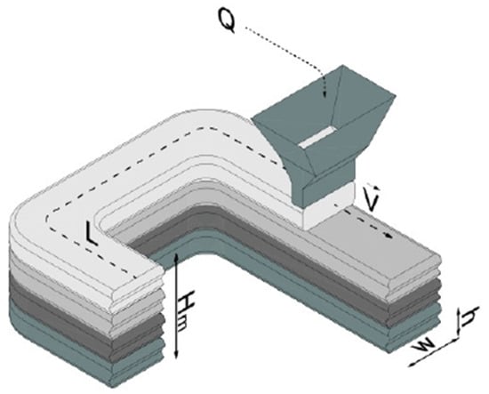
Figure 14.
Schematic of a layer extrusion showing different parameters of the 3D printing where Q is the flow, V is the speed, L is the total length of the printed layer, h is the height of a layer, w is the width of the layer, and Hm is the total height of the structure [51].
3.2. Experiments at Fresh State
For 3D printing, characterization of the material’s fresh properties is not standardized, but different indicators have been developed to satisfy the needs for the specific 3D-printed mixtures. Some evaluations for 3D mixtures allow evaluation of different indicators.
3.2.1. Rheology
The ability of a paste to be printed depends on its flowability and the printer model. The paste viscosity must be adapted to the technology used. For instance, a high-viscosity cementitious mixture could be used for a brick extrusion strategy (yield stress higher than 500 Pa) (Figure 15), whereas a low viscosity cementitious mixture allows spreading of deposition strategies (yield stress lower than 100 Pa) (Figure 15) [19]. Rheological properties must also be adapted during printing process stages. For example, during pumping, extrusion, or deposition stages, the evolution of pastes’ plasticity is required as printing advances.
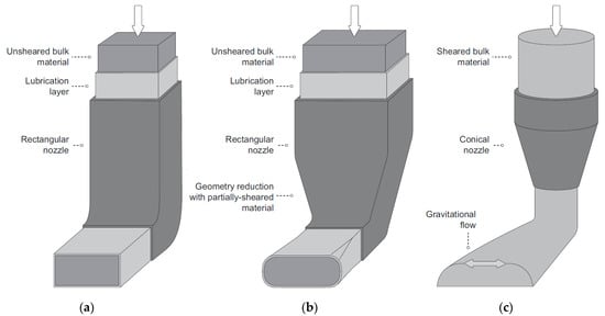
Figure 15.
Strategy of deposition. (a) Extrusion with a very stiff material; (b) more realistic case of extrusion with a sufficiently stiff material; (c) extrusion with very flowable material [19].
Some parameters can impact the 3D printing process like printing strategy and printer characteristics. The rheological behavior of the pastes is often characterized by either of two viscoplastic models [83]:
- The Bingham model, characterized by a linear dependency of shear stress τ with the shear rate . This model applies for shears above a threshold also call yield stress characterizing the minimum stress , for which the mixture deforms:where μ is the plastic viscosity [84,85].
- The Herschel–Buckley model considers that the fresh mixture becomes fluid when the yield stress is reached. The difference between this model and the Bingham model is the capability to represent non-linear dependencies between shear stress and shear rate:where τ is the shear stress, is the yield stress, μ is the plastic viscosity, is the shear rate, K is the constituency index, and n is the flow behavior index. To be able to compare the K values of different fluids, they must have a similar n value. The constant n is greater than 1 if the mixture is rheo-thickening and between 0 and 1 for a rheofluidizing mixture [85].
These two models cannot best describe the behavior of a 3D-printed cementitious mixture. Indeed, in practice, a delay is commonly observed in the response of two successive measurements, and the mixture is said to be thixotropic. This thixotropy behavior is observed to be reversible in the literature [86].
Different experimental set-ups, measurements, and protocols are used to characterize 3D mix rheological behavior [87]. The mixture is first submitted to a constant shear rate and the evolution of the yield stress recorded as a function of time. With this measurement, the workability period is estimated for the mixture and compared for different formulations [22,76,81,83,88,89]. The evaluation of the thixotropic behavior is then measured. The mixture is subjected to a shear rate profile composed of an increase followed by a decrease (Figure 16) [38,47,90]. This protocol of shear rate variation can either be with an incremental step [21,91], with a threshold process [39,44,80], or with a pre-shear (Figure 16) [9,92,93]. With these protocols, the static and dynamic yield stress and thixotropy can be adequately evaluated.
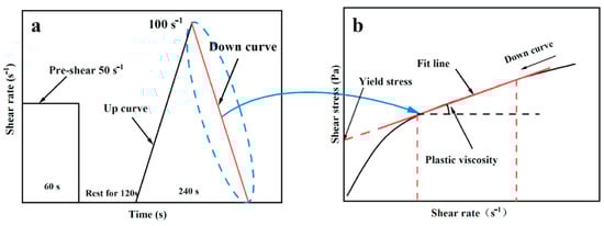
Figure 16.
Process with pre shear and stress increment followed by a resting period; (a) test process; (b) fitting of yield stress and plastic viscosity [93].
Measuring the rheological behavior of mixtures is a good indicator, but rheometers are often limited by the viscosity of the tested 3D-printed material [83]. Other tests are used to empirically estimate the rheological behavior, such as the Abrams’s cone, slump, or slump flow tests. As an overall, rheology can provide insightful information on the adaption of a given cementitious material to 3D printing [2,20,39,69,82,94].
Moreover, non-conventional tests can also be carried out to assess 3D printability of cementitious materials. Among these latter, a variation of the Abrams cone using cylindrical slump tests [47,59,62,65,76,95], the jolting table [22,38,47,59,60,61,62,65,69,82], or penetration tests allow the measurement of mixtures’ resistance [59,60,61,62,65,69,96,97]. These tests are used thanks to being adapted into conventional workability testing, then for their appropriate assessment of rheological properties.
To sum up, rheometers are adapted for liquid mixtures; when a mixture becomes thicker or stickier, substitute tests should be used.
It appears necessary to include other indicators with these rheological measurements.
3.2.2. Extrudability
Extrudability is the aptitude of a mixture to be extracted through a nozzle in a continuous way, while maintaining its dimension. This indicator is usually not quantified numerically but rather visually appreciated. A test to evaluate extrudability consists of the extrusion of a filament followed by a visual inspection of its confirmation and dimensions.
The mixture should not be too fluid in order to have sufficient support, nor too thick in order to be extrudable without discontinuities. According to Le et al. (2012) [37], extrudability is evaluated by producing five groups of one to five rows of 300 mm filaments continuously. This test shows the optimal ratio of sand and different binders: cement, fly ash, and silica fumes. During this test, the total continuous filament extruded out is 4500 mm. If this condition is obtained, then the test is conclusive. For formulations that do not extrude properly, the additive dosage is determined using such a test. With Rahul et al. (2019), the length of the filament is also 300 mm, then a measure of the dimensional conformity is carried out (Figure 17). This measure allows to choose the optimal mixture incorporating silica fumes, nanoclay, and superplasticizer [22]. Extrusion behavior is also studied by depositing a first layer with a special extrusion gun. Khalil et al. (2018) highlight a formulation with sand, Portland cement, sulphoaluminous cement, water, and plasticizer [98]. Finally, Panda et al. (2018), Kazemian et al. (2017) and Kruger et al. (2020) studied the shape conservation and the width of the extruded filament through a nozzle of a certain diameter for a geopolymer mixture; moreover, they study the dimension conformity and consistency for mortar with alternative binders and fibers [41,46,99]. This extrudability indicator allows the choice or improvement of mixtures during the extrusion stage. Extrudability is a first attempt to establish a parameter that evaluates somehow visually the feasibility of 3D printing. Other parameters could be added for a more rigorous study of the mix.
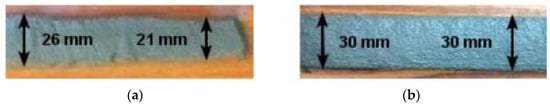
Figure 17.
Test samples to evaluate extrudability; (a) distorted layer; (b) well-printed layer [22].
3.2.3. Workability
Workability is assessed after deformation of a mix submitted to its own weight. This indicator shows the ability of a mix to withstand the structure weight. Workability could be determined by shear vane tests according to Le et al. (2012). A shear vane test is used and could measure the influence of the additive dosage on mortar mixture and typically with cement, fly ash, silica fumes, and sand with size limited to 2 mm. Shear strength is in the order of kPa. High stiffness materials exhibit values above 2 kPa, and adequate shear strength to pass printability is around 0.3 to 0.9 kPa [37].
The slump test can also be used to assess workability and estimate the yield stress. A conical mold is used in this case for the slump tests. This procedure consists of filling the mold with fresh mortar two times to allow tamping at each filling. Then, the mold is removed and the difference in height is measured as the slump value. Hence, a first indication about the rheological behavior is provided. Thixotropy, static yield stress, dynamic yield stress, and plastic viscosity are generally estimated for mortars and geopolymers using the Bingham model. Geopolymers exhibit higher static yield stress than the ones of mortars due to the sticky nature of the formers, but all the three other parameters are usually smaller in geopolymers. In order to ease pumpability, thixotropy values of mixes must be larger than 10,000 N mm rpm [39]. Tay et al. (2019) (Figure 18) describe a printability window with slump and slump flow. The slump flow test is inspired by the slump test. During a slump test, the flow table is dropped 25 times and the diameter of the flow is recorded as slump flow. A large quantity of mortar mixtures is tested with different mix of binders (cement, fly ash, silica fume) [82].
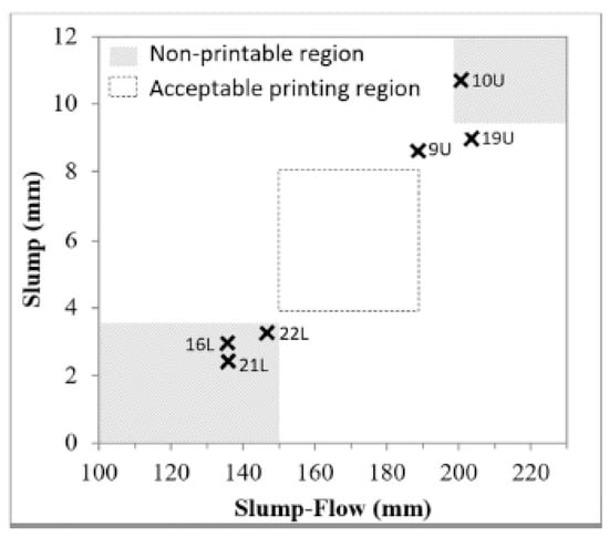
Figure 18.
Printable and non-printable region on slump/slump flow graph [82].
Both Bohuchval et al. (2019, 2020), and Rubio et al. (2017, 2019) [59,60,61,62,65] used cone penetrometer and flow table tests. Cone penetrometers evaluate the consistency of a mixture. A stress is caused by the fall of the cone under gravity. Like in a slump test, a conical mold is filled in two parts. Then, the mold is placed under the falling cone. The cone is dropped for 5 s, and the value of the penetration is measured. The authors selected the best mixture composed of various materials like limestone powder, fly ash, silica fumes, metakaolin, sisal fiber, and polypropylene fibers.
Rubio et al. (2017) also used other types of tests such as a time-dependent extrusion test using a modified joint gun [60].
Compressive tests are used to determine, like at hardened states, apparent elastic modulus. For example, Esposito et al. (2020) [100,101] measured mixtures at different resting times (0, 10, 20, 30 min) using uniaxial compression and compared the values with self-bucking failure. Cylindrical samples with a diameter of 60 mm and a height of 120 mm are tested with a load displacement rate of 30 mm/min. The stress–strain curve is measured and used to determine the elastic modulus and compressive strength and compared to self-bulking failure to avoid its occurrence.
3.2.4. Pumpability
Pumpability is the ability of a mixture to flow under pressure until extraction. Pumpability is determined by finding the moment at which the mixture extracts while maintaining the output rate as a function of the imposed pump speed. For Tay et al. (2019) [82], pumpability is defined by looking at the width of the beads as a function of print speed. For Khalil et al. (2018) [98], this measure is determined by controlling of the length of the ground layer as a function of speed. For Lafhaj and Dakhli (2019) [102], pumpability is the threshold of pressure that allows a possible flow. A good pumpability is not necessary for a good printability if shape retention is not satisfactory or if the production of additional layers in heights is not verified.
3.2.5. Buildability
Buildability is the ability of an extruded layer to support both its own weight and the weight of the above layers. The commonly used method to measure buildability is to estimate the maximum number of overlapping layers before collapse of the structure. The maximum number of layers or maximum reachable height without structure collapse is then measured. Often, mixtures can easily be differentiated with buildability tests. For example, Rahul et al. (2019) and Le et al. (2012) tried using silica fumes, nanoclay, and superplasticizer to assess constructability [22,37,47,81,82,98,103]. Without extruding the mixture, buildability tests can be performed using squeeze flows between two parallel plates [46,88], or by a simple control of the stability of a freshly made cylinder with a mold [46,76], or using non-destructive measurement with ultrasonic waves measurement [64].
3.2.6. Usability Window—Time Use (Open Time)
The open time or usability window is the time interval during which the mixture can be used. Since the mix changes with time, it is necessary to determine when it becomes unprintable. For example, if the mixture starts to cure, it may not complete the print any longer.
This time interval is determined with a time-dependent collapse test. For Le et al. (2012), the variation of the shear strength test is evaluated as a function of time. The measure allows to determine if additives can be used, and in this case the good amount [37]. Buswell (2018) assessed the open time using the buildability as a function of time (Figure 19) [68].
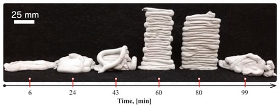
Figure 19.
Evolution of the buildability as a function of time with a maximum height obtained at 60 min (adapted [68]).
In other words, the ability of the mixture to pass the nozzle determines the operating time. When it becomes difficult for the mixture to be extracted, the usability time window is over [39]. Another method to determine the operating window is to monitor rheological parameters [22,44], using a penetrometer [46], a Vicat plunger [93], a resistance to water penetration test, and/or by semi-adiabatic calorimetry [22]. The time-dependent buildability makes it possible to determine the minimum and maximum usable time after the start of mixing [46].
3.2.7. Time between Two Successive Layers
Adding to the difficulty of properly choosing the operating time, it is also necessary to determine the time laps needed before printing a new layer. The 3D-printed structure is self-supporting if the cold joint is strong enough between two successive layers. A too-short printing time between layers will lead to bad buildability, while too large times will let layers be insufficiently bonded to each other [22,68]. In addition, layer deformation can occur, which also depends on the printing time interval between two layers [46].
3.2.8. Object Printing in Its Entirety
The final object print validates the manufacturing process. All previous steps can only be validated after this point. Three-dimensional-printed objects can be rather basic like simple cylinders or much more complex object like a whole bench (Figure 20) [37,104]. Even if all the previous validation steps have been successfully carried out, adaptions of the printer parameters can still be operated to improve the process [46,98]. A common practice is to first print a simple-geometry sample used to adjust printing speed, possible defect removal, flow parameters, and buildability, then to carry on more complex shapes and structures [21,23,81].
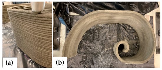
Figure 20.
Three-dimensional-printed bench by extrusion method; (a) during 3D printing process; (b) top-view (adapted from [104]).
3.3. Experiments at Hardened State
Hardened state properties for 3D-printed objects are also evaluated by mechanical strength tests. Additional tests can be performed to check whether the material deposition process is working properly. The shaping process tends to make the material anisotropic, which leads to a decrease in their mechanical performance along some directions compared to cast concrete [3]. The strength measurement will consequently have to be operated to probe this performance difference as a function of direction. Durability tests estimate the service life of a material under given environmental conditions and can also be applied for 3D-printed materials.
3.3.1. Compressive Strength
Compressive strength is estimated by performing a destructive test, where a sample is subjected to compression using a press. The differences between the tests are especially visible in the choice of the sample subjected to the load and in its construction. Specimen with different shapes (cubes, pavers, cylinders, etc.) and various porosities do not behave the same under load. In the case of 3D-printed samples, compressive strength specimens can either be cut out from a larger printed part, printed to the right dimensions, casted, or printed in a mold.
As usual for classical mortars and concretes, in order to study the influence of the mix design on the compressive strength, cubes extracted from different mixes are compared to samples cast in three directions after 7, 14, and 28 days [39]. Similarly, the size of the aggregates is selected on cylindrical sample castings after 14 and 28 days of curing [34], or on prisms after 1 and 7 days [21,42,93].
In order to evaluate the effect of 3D printing on the strength of the object, Le et al. (2012) tested extracted cubes, in comparison with cast samples, at different time intervals of 1, 7, 28 and 56 days after printing, along three perpendicular directions [36]. With Panda et al. (2018), the tests were also carried out on extracted and cast cubes after 7 days of curing [41]. Other authors use the cast and printed samples in the molds to see the influence of the layering [98]. Cylindrical printed samples are compared to the standard by Asprone [20]. Two printing techniques, spray and extrusion, are compared on prisms in two perpendicular directions after 14 days [48].
The influence of the printing parameters is evaluated with extracted cubes compared to samples cast after 7 days in the three directions (Figure 21) [40]; cast cubes are tested after 1, 3, 7, and 28 days [95].
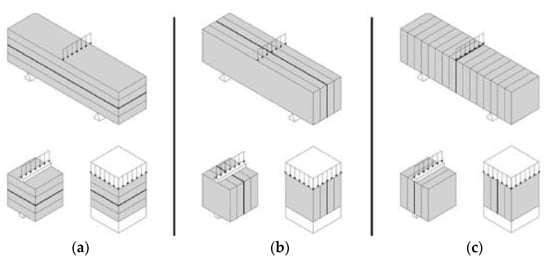
Figure 21.
Three possible orientations for compressive strength testing. (a) Orientation I; (b) orientation II; (c) orientation III [40].
The influence of reinforcements and fibers is also evaluated on extracted and cast cubes along and perpendicular to the printing direction after 7 days [43] and 28 days [23]. To select the optimal quantity of fiber, the presence of fibers in the samples, and their effects on the mechanical strength, the compressive strengths of cubes printed after 28 days along three dimensions [45] and on extracted and cast cubes after 7 days [61] can be compared.
Most tests show that printed samples exhibit a lower mechanical strength than cast samples; however, in some studies, the opposite behavior is observed [48].
3.3.2. Flexural Strength
In a similar way, flexural strength is measured by a destructive test in which a specimen is subjected to bending using a press. Often these tests are performed using a three-point or four-point flexural set-up [57].
For measurements with three-point bending, the influence of the printing direction on the flexural strength of extracted pavers along two or three directions are used [39,42,45]. With the same set-up, the influence of different printing parameters such as the time interval between two layers, the height of the nozzle, and the dehydration of the layers are measured with the help of parallelepipeds sawn in three directions (Figure 21) [40]. The main parameters that influence flexural strength in this case are layer dehydration and nozzle height. The results in this case remain identical to the cast sample.
The performance of the reinforcements is determined on cut pavers trimmed perpendicular to the direction of the reinforcements [23,43,105]. In this situation, reinforced 3D-printed samples tend to have better results than non-reinforced samples. The type of reinforcement and print path play a major role in flexural strength.
Likewise, four-point bending tests were carried out on pavers extracted from a larger object to evaluate the influence of the printing path on the flexural strength [36].
3.3.3. Tensile Strength
The tensile strength is estimated by a destructive test where a sample is subject to tension with a press. This test is less commonly used; cubes can also be tested along two or three directions with varying time intervals between layers [40,44,45]. Tensile testing is also achieved by splitting tests on cast cylinders [34].
The literature review shows in this case that there is no apparent dependency of tensile strength in regard to layer orientation, contrary to compressive and flexural strength [40].
3.3.4. Bonding between Layers
The correct cohesion between two consecutive layers is controlled lively by visual inspection during 3D printing and depends among other parameters on the durability of the mix. If the adhesion is not optimal, this can be due to the mixture or the printing parameters. Cold joints are optimal if the layers are well deposited (depending on the quality of the layer and the deposit of the layer). For closer, but destructive, inspection and diagnosis, cohesion can be assessed using microphotography and/or scanning electron microscopy (SEM) [68]. Also, adhesion strength tests can be carried out by bending printed or extracted cylinders twice with a given time interval [36,106] and resulting strengths compared to the ones of cast samples [42,44]. Samples can also be specifically manufactured for the test. These are prisms consisting of two layers, and each layer is glued to the tensile plates [107].
3.3.5. Reinforcement Pull-Out Resistance
The reinforcement pull-out test is used to check the adhesion of the reinforcement inclusions to the matrix. The sample is submitted to a mechanical stress and determines whether the reinforcement is well integrated into the matrix. Reinforcements are subject to tearing, using a sample with a reinforcement that comes out [57,105,108,109,110].
The pull-out test shows a difference between cast and printed concrete, due to the quality of the process. Cast samples tend to have a greater pull-out resistance that is linked to the used reinforcement [105,108,110]. However, Baz et al. (2020) show that the strength is almost the same for cast and 3D-printed samples. The timeline of reinforcement insertion is critical in the fabrication process, which gives a lesser pull-out strength. The workability of the mix and printing direction does not appear to influence the pull-out resistance [109].
3.3.6. Density
The density is measured and compared with the theoretical density of the mix. Density measurements can indicate either if the process was correctly archived or the presence of defects that could compromise the structure. For Buswell (2018), the measurement is made by water saturation. This measurement determines the quality of the print according to the formulation [68]. For Hambach et Volkmer (2017), the density measured by helium pycnometer is used to determine the influence of the printing pattern. Patterns with similar results to the cast samples are then selected [23]. Good printing as shown in Figure 22 has higher density than a casted one [36]. Density is often associated with porosity tests, which in turn helps in understanding durability properties for cast and printed samples.
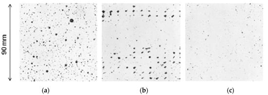
Figure 22.
Three specimens for void measurement; (a) mold-cast; (b) poor printing; (c) good printing [36].
3.3.7. Porosity
The apparent porosity of a printed sample is a measure of the quality of the print. For example, a coarse print can exhibit a large porosity with large pore diameters and irregular pore distributions. This porosity induces a lower strength than a cast material. The porosity is determined by the presence of black contrasts in image analysis (Figure 22). This analysis determines mean pore diameters, total pore surfaces, and distributions of pores locations and diameters, all somehow reflecting the quality of the print. Eventually, image analysis can also provide pore sizes anisotropy measurement. When the print is correct, the 3D-printed sample can outperform the cast sample as suggested by results from vacuum saturation [42] and helium pycnometer [23]. Porosity is also determined by water absorption. Samples are immersed in a water tank under vacuum. The porosity is then determined by hydrostatic weighting. Mixtures with and without accelerators and retarders are compared, and this indicates that additives influence the total porosity [102]. Oxygen permeability gives an indication of the interconnectivity of the pores. This indicator gives an idea of the printing process quality compared to a conventional production system. In fact, for Moelich et al. (2021), the proportion of connected pores implies a decrease of cohesion [111].
3.3.8. Shrinkage
Shrinkage of concrete refers to dimensional changes before, during, or after its hardening. Using larger cement contents in the mixture gives rise to 3D-printed structures highly susceptible to shrinkage. Three-dimensional printing allows printing of a larger surface area in comparison to the cast object. The defects resulting from large surface printing weaken the structure and compromise the service life of the 3D-printed object. Reducing shrinkage through formulation or curing conditions improves the mechanical strength of the material. For example, Le et al. (2012), shrinkage measurements are performed using iron molds and sensors that allow the visualization of length variation [36]. Moelich et al. (2020, 2021) used sensors on the different layers of a printed sample, the developed system being able to monitor the shrinkage of individual layers within a controlled environment [111,112]. Another large study of Moelich et al. (2020) reports the deformation and cracking of structures by analyzing images over time as a function of curing conditions [112]. To evaluate mixture design, in a study by Zhang et al. (2021), dimensions are controlled using a strain captor on the 3D-printed object and mold samples [113].
3.3.9. Chloride Ion Penetration Resistance
The chloride ion permeability of concrete is a measure of the durability of mortar or concrete, for instance, in a marine environment. The aim is to measure chloride anion diffusion in the depth of the material over time. The influence of the layering created during the printing process is evaluated [102,111,113,114]. For Van der Putten et al. (2020), a mortar is evaluated between cast and 3D-printed samples with different time gaps. All surfaces are covered with double epoxy in order to prevent Cl diffusion from the surfaces, except one let uncovered which deserves chloride anions entrance window. This sample preparation ensures unidimensional chloride diffusion for an easy modelling. Samples are submerged on a 165 g/L NaCl solution at 20 °C. After various times of exposure, a solution of silver nitrate is sprayed on a sample cut, to reveal the diffusion front as a function of exposure time. Three-dimensional-printed samples exhibit larger chloride anion penetration. In addition, the longer the interlayer time gap is, the greater the chloride penetration is [114]. Moelich et al. (2021), cast and cut printed samples which were then put in a tank vacuum saturated with NaCl solution. An electrical current is applied to accelerate the attack of ions. Mixtures adapted for 3D printers have usually lower chloride ion penetrations than standard mortar, mainly due to their cement content [111].
3.3.10. Sorption
Material sorption measures the ability of a material to absorb and restore ambient moisture by capillary action. In this case, it is the height of the diffusion depth as a function of time that is measured. The more water the sample absorbs, the larger the diffusion [115]. In addition, variation of mass moisture content on the samples at different levels of relative humidity (RH) can be measured, which allows plotting of sorption and desorption curves. The hygroscopic characteristics are then evaluated (Figure 23). Typically, if moisture is large, samples can be more sensitive to aggressive agents [102]. Since 3D-printed materials are usually more porous than usual casts, they are subjected to more moisture uptake under RH given values.
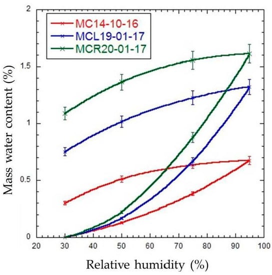
Figure 23.
Sorption/desorption isotherms of cementitious material specimens [102].
3.3.11. Freeze–Thaw Resistance
Freeze–thaw cycles give an indication of the deterioration of a material submitted to cyclic temperature variations over its lifetime. The sample is subjected to a definite number of temperature cycles ranging from room temperature to sub-zero temperatures. The evolution of the mechanical strength as well as the weight loss can be analyzed to investigate the degradation of the material under freezing–unfreezing conditions. The influence of the material components and the shaping process can then be assessed. Zhang et al. (2021) chose the mix and type of manufacture with the number of cycles. Mixtures contain different sand/binder ratios and different polypropylene fiber. Three-dimensional-printed objects have lower dynamic modulus and weight loss than mold cast (Figure 24) [113]. The results converge with Weger et al. (2018), who showed the 3D-printed object dynamic modulus evolution during the freeze–thaw cycle [116].
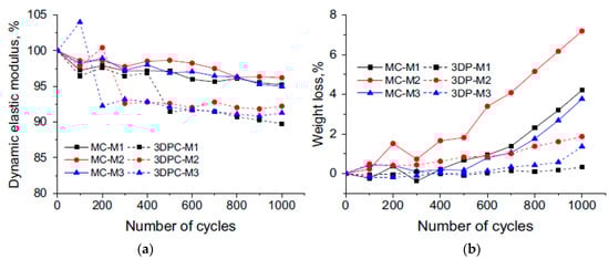
Figure 24.
(a) Relative dynamic elastic modulus and (b) weight loss during freeze–thawing cycles for mold cast (MC) and 3D-printed (3DP) samples [113].
3.3.12. Fire Resistance
The fire resistance gives an indication of the performance of the material against ignition. The samples are subjected to high temperatures in an oven for a given period of time. The evolution of the mechanical properties is evaluated as a function of temperatures [8,100,117]. Xiao et al. (2021) controlled properties on different mixtures, 3D-printed and cast specimens after exposition for 1 h to elevated temperatures. Mass loss, compressive, and flexural strengths are measured after 200 °C, 400 °C, 600 °C, and 800 °C expositions. Regardless of the mixture, loss of mechanical properties is similar for 3D-printed and mold cast samples [117]. D’Hondt et al. (2020) also measure compressive and flexural strengths during 2 h of exposures at 250 °C, 400 °C, and 600 °C. Specimens are extracted, horizontally and vertically, on 3D-printed parts. The different properties have not been significantly modified after exposition [100,118]. Kruger et al. (2020) control fire resistance with one-dimension tests. A 1D heat test is set up, using direct irradiation perpendicular to the front face. The samples were heated until the front and back faces reached 500 and 200 °C, respectively. The temperature resistance of the 3D-printed samples steel fiber (with orthogonal steel reinforcements) exhibit better mechanical performances than non-reinforced ones [100,119].
3.3.13. Acidic Attack Resistance
The deterioration of cementitious materials depends on the acid (nitric [120] or sulfuric acid [120,121]). Frequently, this test is used when the formulation contains substitute binders, which can often be the case to improve the rheology of the paste. For sulfuric acid, Baz et al. (2021) use a 1% to 3% sulfuric acid bath. They compare different mortar mixtures and 3D-printed and cast samples for 3 to 56 days (Figure 25). Materials are Ordinary Portland Cements, sand, limestone filler with admixtures, a high ratio water reducer, and a viscosity modifying agent. The control of acidic attacks is based on mass loss. The pore size distribution is affected by the process. Cast and 3D-printed samples are behaving the same under acid attack. However, the pore size distribution is different. Overall, 3D-printed samples seem to exhibit decreased micro porosity and increased resistance to acid attack [121].
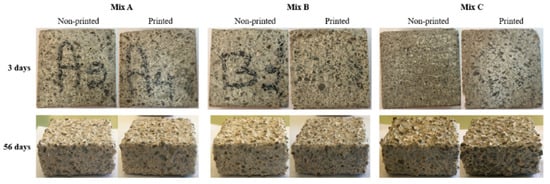
Figure 25.
Progressive damage of printed and non-printed samples for three mix in 1% acidic solution [121].
3.3.14. Sulfate Attack Resistance
Sulfate attack of concretes is based on a degradation process called decalcification of the concrete in 5% sodium sulfate solution. The sulfate ions pass through the pores and react with the calcium ions. After 28 days of curing, at 24 h cycles, the mechanical strength is assessed on 3D-printed and cast samples for different mixtures. For the same mixture, 3D-printed samples resist more to sulfate attacks than cast samples (Figure 26a) [113].
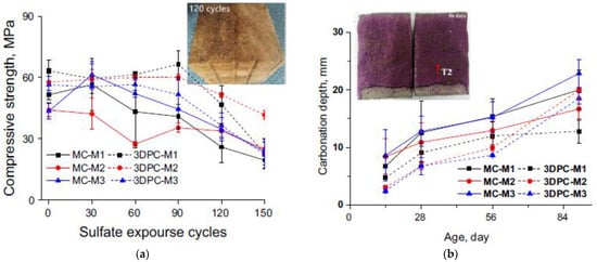
Figure 26.
(a) Compressive strength changes with sulfate exposure period for cast (MC) and 3D-printed (3DPC) specimens. (b) Relationships between carbonation depths and exposition time for mold cast sample (MC) and 3D-printed sample (3DPC) [113].
3.3.15. Carbonation
The carbonation depth measurement allows the evaluation of the transformation of the hydrated phases of cementitious materials subjected to atmospheric CO2 resulting in a progressive degradation. In the laboratory, the sample is subjected to an accelerated degradation due to CO2 exposition. After different exposition times, phenolphthalein is sprayed on the freshly split section. Carbonation depths are measured on 3D-printed and cast samples and compared (Figure 26b). Three-dimensional samples seem to exhibit better resistance to CO2 diffusion in comparison to cast samples. Finally, 3D-printed samples have better results than cast [113]. Sun et al. measured carbonation with accelerated carbonation test on 3D-printed and cast samples. The 3D-printed samples were cut along three different directions. In this case, 3D-printed samples had a higher degree of carbonation than a cast specimen. This difference is due to a higher porosity induced by the multiple layer interface [122]. These results suggest that more data are needed to conclude on the 3D-printed parameters assessment on carbonation ingress.
4. Recent Advances of 3D Printing Applied to Architecture
These paragraphs about 3D printing in architecture were not intended initially, but we thought that architecture should always be kept in sight when discussing 3D printing in buildings. We aim to provide recent architectural breakthroughs, that were made possible thanks to the recent advances shown previously in our paper. The benefits often put forward by 3D printing advocates are reducing costs, reducing material waste, increasing the quality of production, and the quality of work. However, the main benefit of 3D printing in industries is the liberty of shape. It is also preferable to create non-standard designs. For example, simple shapes such as bricks are simpler and cheaper to manufacture using conventional methods rather than using 3D printing. Architects can therefore imagine original shapes that are costly to achieve using conventional technologies. What is more, the construction industry in collaboration with architects needs very large-scale manufacturing, which is a technological challenge that can be solved by 3D printing [123]. We present here some structures that efficiently use the recent advances of 3D printing.
- Housing:
Industries aim to manufacture large structures to show the capabilities of 3D printing. In most cases, house-building projects take an important part of the total number of the studied 3D printing project, as García-Alvarado et al. suggest in their study [124]. In García Alvarado et al.’s findings, the projects hope to achieve multi-storey homes. To attain this ambition, the Design for Manufacture and Assembly (DfMA) technique can be adopted for analyzing and enhancing product design for both economical production and assembly [125]. Figure 27 shows designs conceived using shapes with curvature that can be printed on site as an assembly of multiple parts.
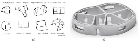
Figure 27.
(a) Plans of 3D-printed constructions recorded by García-Alvarado et al. (b) Model of a 3D-printed construction [124].
Some of the drawbacks of using unconventional shapes is the need to accommodate plumbing, electrical wiring, and furniture. For this reason, some projects have adapted certain elements to have straight walls or incorporate double walls that make it easier to install these elements [124]. Often, these projects are limited to a single building. However, as the project developed by ICON shows [126], rapid home 3D printing could facilitate access to accommodation for people who need it, such as homeless, families in need, and victims of climate change [127].
- Walls:
The design of walls allows the creation of innovative and structural elements and even new living spaces [128,129]. Textured and/or curved walls obtained by 3D printing could also offer other benefits in terms of thermal and acoustic performances (Figure 28) [130,131,132].
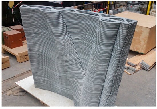
Figure 28.
Three-dimensional-printed high-performance concrete multifunctional wall [4].
- Columns:
The manufacture of columns involves elongated and load bearing structures. Three-dimensional printing gives the ability to produce highly ambitious and optimized shapes, which are often highlighted with this kind of construction. Different printing techniques are used to obtain the most architectural shapes. For example, structures are obtained by 3D printing of formwork [133], by extrusion [134], or by Smart Dynamic Casting [27] (Figure 29).
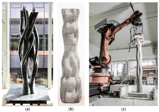
Figure 29.
(a) Branching column fabricated in three parts by using a simultaneous process printing and filling [133]; (b) 3DCP columns by extrusion process [134]; (c) column prototype by Smart Dynamic Casting [51].
- Bridge:
Architecture could also be applied to bridges shape using 3D printing. This type of processing reduces the amount of material used, which makes it possible to achieve optimized and original shapes. Three-dimensional printing can be used to print bridges in several parts, which can then be assembled (Figure 30) [135,136,137] or produced in a single print run [138].
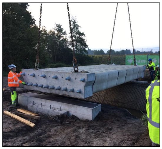
Figure 30.
3DCP bicycle bridge printed by Eindhoven University of Technology [24].
- Others:
In some other cases, 3D printing of concrete enables structures to be manufactured on a macroscopic and large scale. This custom-made manufacturing allows us, for example, to draw inspiration from nature to restore natural habitats, such as coral reefs, [139,140] or artificial reefs for the biodiversity of marine fauna [141].
5. Conclusions
This article gives an overview of recent advances in 3D printing cementitious materials. We present in our work multiple 3D printing structure production methods, together with critical parameters that influence their performance. Recent advances in 3D printing technologies show that:
- Extrusion processes are more flexible and offer a variety of shapes to suit the geometry of the object, whether it is on-site, a module, or a small object. Typically, printing methods such as robots, cartesian printers, gantries, and delta printers are generally combined with different mixing, pumping, and nozzle systems to achieve the desired result.
- Other used processes are based on material jetting, binder jetting, and injection. These techniques eliminate the layer effect. These techniques are more suitable for making complex shapes but more complex to use (with the use of carrier materials to remove) and cannot yet be used on site.
- Reinforcements are introduced in different ways: in the mix, in the layers, or in the hardened state. The focus here is to improve mechanical properties and the bond between printing layers. Supports are added to allow greater printing freedom, these supports are either installed manually or printed in parallel with another material or set up with the same material.
As it is shown in our review, to obtain optimal performances with 3D printers, some key parameters must be controlled such as:
- As a major key parameter, the rheology, which is influenced by the choice of binders, either substitutes binders or mineral components. This rheology is also controlled by the quantity of water and the addition of aggregates or fibers. This mix design must be adapted to the printing techniques and the desired rheology. Organic additions are also operated to correct the mix design.
- The second key parameters are linked to the design of the 3D-printed object. They can encompass the dimensions of the object to be printed its size, height, angle, and filling pattern.
- The third key parameter is linked to the characteristics of the 3D printing apparatus like the size and shape of the nozzle, speed, flow rate, size and width of the layers, and time lag between two layers.
- The final key parameters which can mainly be for on-site 3D printing objects are more difficult to control, like environment, hydration, and contact surface.
With the recent development of 3D-printed structures, existing methods for testing physical, mechanical, and durability properties are exampled in our review. These testing methods can either be at:
- The fresh state, these tests are performed to evaluate the rheology and printability of the mixture: extrudability, workability, pumpability, buildability, usability window, and time between two successive layers.
- The hardened state, used to determine whether the printing is properly produced. These tests are either be related to microstructure (porosity, density, shrinkage, and sorption) or mechanical (compressive strength, flexural strength, tensile strength, layer’s cohesion, and resistance to reinforcement pull-out) or durability (resistance to chloride ions, freeze/thaw resistance, fire resistance, resistance to acidic attack, resistance to sulphate attack, and carbonation).
The multitude of printing methods, material designs, fresh state, and hardened state tests make it difficult to normalize 3D printing testing methods yet. It is not unlikely that a standard on testing for 3D printed objects will shortly appear. This article provides a contribution for achieving this purpose.
Author Contributions
Writing—original draft preparation, M.A., A.F., B.E.H., D.C. and M.S.; writing—review and editing, M.A., A.F., B.E.H., D.C., M.S. and N.S.; supervision, A.F., B.E.H., D.C. and N.S. All authors have read and agreed to the published version of the manuscript.
Funding
This research was co-funded by both the Normandie region (France) under the PhD thesis grant RIN allocations 2020 and the ESITC Metz with an equal cofounding.
Data Availability Statement
No new data were created or analyzed in this study. Data sharing is not applicable to this article.
Acknowledgments
This work has been co-financed by the Normandie region (France) under the PhD thesis grant. The authors thank the Normandie region and ESITC Metz for their funding and contribution.
Conflicts of Interest
The authors declare no conflict of interest.
References
- Wu, P.; Wang, J.; Wang, X. A critical review of the use of 3-D printing in the construction industry. Autom. Constr. 2016, 68, 21–31. [Google Scholar] [CrossRef]
- Souza, M.T.; Ferreira, I.M.; Guzi de Moraes, E.; Senff, L.; Novaes de Oliveira, A.P. 3D printed concrete for large-scale buildings: An overview of rheology, printing parameters, chemical admixtures, reinforcements, and economic and environmental prospects. J. Build. Eng. 2020, 32, 101833. [Google Scholar] [CrossRef]
- Kristombu Baduge, S.; Navaratnam, S.; Abu-Zidan, Y.; McCormack, T.; Nguyen, K.; Mendis, P.; Zhang, G.; Aye, L. Improving performance of additive manufactured (3D printed) concrete: A review on material mix design, processing, interlayer bonding, and reinforcing methods. Structures 2021, 29, 1597–1609. [Google Scholar] [CrossRef]
- Gosselin, C.; Duballet, R.; Roux, P.; Gaudillière, N.; Dirrenberger, J.; Morel, P. Large-scale 3D printing of ultra-high performance concrete—A new processing route for architects and builders. Mater. Des. 2016, 100, 102–109. [Google Scholar] [CrossRef]
- X-Reef, in the Calanques National Park—XtreeE. Available online: https://xtreee.com/en/project/xreef/ (accessed on 28 June 2023).
- Mikahila, L. The Most Impressive 3D-Printed Bridge Projects, 3Dnatives, 5 November 2021. Available online: https://www.3dnatives.com/en/3d-printed-bridge-051120214/ (accessed on 28 June 2023).
- Al-Noaimat, Y.A.; Chougan, M.; Al-kheetan, M.J.; Al-Mandhari, O.; Al-Saidi, W.; Al-Maqbali, M.; Al-Hosni, H.; Ghaffar, S.H. 3D printing of limestone-calcined clay cement: A review of its potential implementation in the construction industry. Results Eng. 2023, 18, 101115. [Google Scholar] [CrossRef]
- Rehman, A.U.; Kim, J.-H. 3D Concrete Printing: A Systematic Review of Rheology, Mix Designs, Mechanical, Microstructural, and Durability Characteristics. Materials 2021, 14, 3800. [Google Scholar] [CrossRef]
- Hou, S.; Duan, Z.; Xiao, J.; Ye, J. A review of 3D printed concrete: Performance requirements, testing measurements and mix design. Constr. Build. Mater. 2021, 273, 121745. [Google Scholar] [CrossRef]
- Shahrubudin, N.; Lee, T.C.; Ramlan, R. An Overview on 3D Printing Technology: Technological, Materials, and Applications. Procedia Manuf. 2019, 35, 1286–1296. [Google Scholar] [CrossRef]
- Pessoa, S.; Guimarães, A.S.; Lucas, S.S.; Simões, N. 3D printing in the construction industry—A systematic review of the thermal performance in buildings. Renew. Sustain. Energy Rev. 2021, 141, 110794. [Google Scholar] [CrossRef]
- Sakin, M.; Kiroglu, Y.C. 3D Printing of Buildings: Construction of the Sustainable Houses of the Future by BIM. Energy Procedia 2017, 134, 702–711. [Google Scholar] [CrossRef]
- Perrot, A. (Ed.) 3D Printing of Concrete: State of the Art and Challenges of the Digital Construction Revolution, 1st ed.; ISTE: London, UK; Wiley: Hoboken, NJ, USA, 2019. [Google Scholar]
- Gibson, I.; Rosen, D.; Stucker, B. Additive Manufacturing Technologies; Springer: New York, NY, USA, 2015. [Google Scholar] [CrossRef]
- Marchon, D. Hydration and rheology control of concrete for digital fabrication_ Potential admixtures and cement chemistry. Cem. Concr. Res. 2018, 112, 96–110. [Google Scholar] [CrossRef]
- Arnaud, P.; Damien, R.; Sofiane, A. Défis à relever en termes de rhéologie des matériaux cimentaires pour une impression 3D par extrusion/dépôt. Acad. J. Civ. Eng. 2018, 36, 5. [Google Scholar]
- Dilberoglu, U.M.; Gharehpapagh, B.; Yaman, U.; Dolen, M. The Role of Additive Manufacturing in the Era of Industry 4.0. Procedia Manuf. 2017, 11, 545–554. [Google Scholar] [CrossRef]
- Mohan, M.K.; Rahul, A.V.; De Schutter, G.; Van Tittelboom, K. Extrusion-based concrete 3D printing from a material perspective: A state-of-the-art review. Cem. Concr. Compos. 2021, 115, 103855. [Google Scholar] [CrossRef]
- Mechtcherine, V.; Bos, F.P.; Perrot, A.; da Silva, W.R.L.; Nerella, V.N.; Fataei, S.; Wolfs, R.J.M.; Sonebi, M.; Roussel, N. Extrusion-based additive manufacturing with cement-based materials—Production steps, processes, and their underlying physics: A review. Cem. Concr. Res. 2020, 132, 106037. [Google Scholar] [CrossRef]
- Asprone, D.; Auricchio, F.; Menna, C.; Mercuri, V. 3D printing of reinforced concrete elements: Technology and design approach. Constr. Build. Mater. 2018, 165, 218–231. [Google Scholar] [CrossRef]
- Mohan, M.K.; Rahul, A.V.; De Schutter, G.; Van Tittelboom, K. Early age hydration, rheology and pumping characteristics of CSA cement-based 3D printable concrete. Constr. Build. Mater. 2021, 275, 122136. [Google Scholar] [CrossRef]
- Rahul, A.V. 3D printable concrete: Mixture design and test methods. Cem. Concr. Compos. 2019, 97, 13–23. [Google Scholar] [CrossRef]
- Hambach, M.; Volkmer, D. Properties of 3D-printed fiber-reinforced Portland cement paste. Cem. Concr. Compos. 2017, 79, 62–70. [Google Scholar] [CrossRef]
- Salet, T.A.M.; Ahmed, Z.Y.; Bos, F.P.; Laagland, H.L.M. Design of a 3D printed concrete bridge by testing. Virtual Phys. Prototyp. 2018, 13, 222–236. [Google Scholar] [CrossRef]
- Dielemans, G.; Lachmayer, L.; Recker, T.; Atanasova, L.; Hechtl, C.M.; Matthäus, C.; Raatz, A.; Dörfler, K. Mobile Additive Manufacturing: A Case Study of Clay Formwork for Bespoke in Situ Concrete Construction. In Third RILEM International Conference on Concrete and Digital Fabrication; Buswell, R., Blanco, A., Cavalaro, S., Kinnell, P., Eds.; RILEM Bookseries; Springer International Publishing: Cham, Swtizerland, 2022; pp. 15–21. [Google Scholar] [CrossRef]
- Buswell, R.; Blanco, A.; Cavalaro, S.; Kinnell, P. (Eds.) Third RILEM International Conference on Concrete and Digital Fabrication: Digital Concrete 2022; RILEM Bookseries; Springer International Publishing: Cham, Swtizerland, 2022; Volume 37. [Google Scholar] [CrossRef]
- Lloret-Fritschi, E.; Wangler, T.; Gebhard, L.; Mata-Falcón, J.; Mantellato, S.; Scotto, F.; Burger, J.; Szabo, A.; Ruffray, N.; Reiter, L.; et al. From Smart Dynamic Casting to a growing family of Digital Casting Systems. Cem. Concr. Res. 2020, 134, 106071. [Google Scholar] [CrossRef]
- Reiter, L.; Wangler, T.; Roussel, N.; Flatt, R.J. The role of early age structural build-up in digital fabrication with concrete. Cem. Concr. Res. 2018, 112, 86–95. [Google Scholar] [CrossRef]
- Arunothayan, A.R.; Nematollahi, B.; Ranade, R.; Bong, S.H.; Sanjayan, J.G.; Khayat, K.H. Fiber orientation effects on ultra-high performance concrete formed by 3D printing. Cem. Concr. Res. 2021, 143, 106384. [Google Scholar] [CrossRef]
- El Cheikh, K.; Rémond, S.; Khalil, N.; Aouad, G. Numerical and experimental studies of aggregate blocking in mortar extrusion. Constr. Build. Mater. 2017, 145, 452–463. [Google Scholar] [CrossRef]
- He, L.; Tan, J.Z.M.; Chow, W.T.; Li, H.; Pan, J. Design of novel nozzles for higher interlayer strength of 3D printed cement paste. Addit. Manuf. 2021, 48, 102452. [Google Scholar] [CrossRef]
- Yang, L.; Sepasgozar, S.M.E.; Shirowzhan, S.; Kashani, A.; Edwards, D. Nozzle criteria for enhancing extrudability, buildability and interlayer bonding in 3D printing concrete. Autom. Constr. 2023, 146, 104671. [Google Scholar] [CrossRef]
- Mostert, J.-P.; Kruger, J. Interlocking 3D Printed Concrete Filaments through Surface Topology Modifications for Improved Tensile Bond Strength. In Third RILEM International Conference on Concrete and Digital Fabrication; Buswell, R., Blanco, A., Cavalaro, S., Kinnell, P., Eds.; RILEM Bookseries; Springer International Publishing: Cham, Swtizerland, 2022; pp. 235–240. [Google Scholar] [CrossRef]
- Zareiyan, B.; Khoshnevis, B. Interlayer adhesion and strength of structures in Contour Crafting—Effects of aggregate size, extrusion rate, and layer thickness. Autom. Constr. 2017, 81, 112–121. [Google Scholar] [CrossRef]
- Khoshnevis, B.; Hwang, D.; Yao, K.-T.; Yeh, Z. Mega-scale fabrication by Contour Crafting. Int. J. Ind. Syst. Eng. 2006, 1, 301. [Google Scholar] [CrossRef]
- Le, T.T.; Austin, S.A.; Lim, S.; Buswell, R.A.; Law, R.; Gibb, A.G.F.; Thorpe, T. Hardened properties of high-performance printing concrete. Cem. Concr. Res. 2012, 42, 558–566. [Google Scholar] [CrossRef]
- Le, T.T.; Austin, S.A.; Lim, S.; Buswell, R.A.; Gibb, A.G.F.; Thorpe, T. Mix design and fresh properties for high-performance printing concrete. Mater. Struct. 2012, 45, 1221–1232. [Google Scholar] [CrossRef]
- Nerella, V.N.; Näther, M.; Iqbal, A.; Butler, M.; Mechtcherine, V. Inline quantification of extrudability of cementitious materials for digital construction. Cem. Concr. Compos. 2019, 95, 260–270. [Google Scholar] [CrossRef]
- Paul, S.C.; Tay, Y.W.D.; Panda, B.; Tan, M.J. Fresh and hardened properties of 3D printable cementitious materials for building and construction. Arch. Civ. Mech. Eng. 2018, 18, 311–319. [Google Scholar] [CrossRef]
- Wolfs, R.J.M.; Bos, F.P.; Salet, T.A.M. Hardened properties of 3D printed concrete: The influence of process parameters on interlayer adhesion. Cem. Concr. Res. 2019, 119, 132–140. [Google Scholar] [CrossRef]
- Panda, B.; Unluer, C.; Tan, M.J. Investigation of the rheology and strength of geopolymer mixtures for extrusion-based 3D printing. Cem. Concr. Compos. 2018, 94, 307–314. [Google Scholar] [CrossRef]
- Rahul, A.V.; Santhanam, M.; Meena, H.; Ghani, Z. Mechanical characterization of 3D printable concrete. Constr. Build. Mater. 2019, 227, 116710. [Google Scholar] [CrossRef]
- Marchment, T.; Sanjayan, J. Mesh reinforcing method for 3D Concrete Printing. Autom. Constr. 2020, 109, 102992. [Google Scholar] [CrossRef]
- Panda, B. Measurement of tensile bond strength of 3D printed geopolymer mortar. Measurement 2018, 113, 108–116. [Google Scholar] [CrossRef]
- Panda, B.; Chandra Paul, S.; Jen Tan, M. Anisotropic mechanical performance of 3D printed fiber reinforced sustainable construction material. Mater. Lett. 2017, 209, 146–149. [Google Scholar] [CrossRef]
- Kazemian, A.; Yuan, X.; Cochran, E.; Khoshnevis, B. Cementitious materials for construction-scale 3D printing: Laboratory testing of fresh printing mixture. Constr. Build. Mater. 2017, 145, 639–647. [Google Scholar] [CrossRef]
- Zhang, Y. Fresh properties of a novel 3D printing concrete ink. Constr. Build. Mater. 2018, 174, 263–271. [Google Scholar] [CrossRef]
- Kloft, H.; Krauss, H.-W.; Hack, N.; Herrmann, E.; Neudecker, S.; Varady, P.A.; Lowke, D. Influence of process parameters on the interlayer bond strength of concrete elements additive manufactured by Shotcrete 3D Printing (SC3DP). Cem. Concr. Res. 2020, 134, 106078. [Google Scholar] [CrossRef]
- Cesaretti, G. Building components for an outpost on the Lunar soil by means of a novel 3D printing technology. Acta Astronaut. 2014, 93, 430–450. [Google Scholar] [CrossRef]
- Lowke, D.; Dini, E.; Perrot, A.; Weger, D.; Gehlen, C.; Dillenburger, B. Particle-bed 3D printing in concrete construction—Possibilities and challenges. Cem. Concr. Res. 2018, 112, 50–65. [Google Scholar] [CrossRef]
- Wangler, T.; Lloret, E.; Reiter, L.; Hack, N.; Gramazio, F.; Kohler, M.; Bernhard, M.; Dillenburger, B.; Buchli, J.; Roussel, N.; et al. Digital Concrete: Opportunities and Challenges. RILEM Tech. Lett. 2016, 1, 67. [Google Scholar] [CrossRef]
- Jipa, A.; Bernhard, M.; Ruffray, N.; Wangler, T.; Flatt, R.; Dillenburger, B. Formwork fabrication freedom for a concrete canoe. Gest. Tecnol. Proj. 2019, 14, 25–44. [Google Scholar] [CrossRef]
- Jipa, A.; Dillenburger, B. 3D Printed Formwork for Concrete: State-of-the-Art, Opportunities, Challenges, and Applications. 3D Print. Addit. Manuf. 2022, 9, 84–107. [Google Scholar] [CrossRef]
- Lloret, E.; Shahab, A.R.; Linus, M.; Flatt, R.J.; Gramazio, F.; Kohler, M.; Langenberg, S. Complex concrete structures. Comput.-Aided Des. 2015, 60, 40–49. [Google Scholar] [CrossRef]
- Lowke, D.; Vandenberg, A.; Pierre, A.; Thomas, A.; Kloft, H.; Hack, N. Injection 3D concrete printing in a carrier liquid—Underlying physics and applications to lightweight space frame structures. Cem. Concr. Compos. 2021, 124, 104169. [Google Scholar] [CrossRef]
- Van Der Putten, J.; De Schutter, G.; Van Tittelboom, K. Surface modification as a technique to improve inter-layer bonding strength in 3D printed cementitious materials. RILEM Tech. Lett. 2019, 4, 33–38. [Google Scholar] [CrossRef]
- Asprone, D.; Menna, C.; Bos, F.P.; Salet, T.A.M.; Mata-Falcón, J.; Kaufmann, W. Rethinking reinforcement for digital fabrication with concrete. Cem. Concr. Res. 2018, 112, 111–121. [Google Scholar] [CrossRef]
- Mechtcherine, V.; Buswell, R.; Kloft, H.; Bos, F.P.; Hack, N.; Wolfs, R.; Sanjayan, J.; Nematollahi, B.; Ivaniuk, E.; Neef, T. Integrating reinforcement in digital fabrication with concrete: A review and classification framework. Cem. Concr. Compos. 2021, 119, 103964. [Google Scholar] [CrossRef]
- Bohuchval, M.; Sonebi, M.; Amziane, S.; Perrot, A. Effect of metakaolin and natural fibres on three-dimensional printing mortar. Proc. Inst. Civ. Eng.-Constr. Mater. 2020, 174, 115–128. [Google Scholar] [CrossRef]
- Rubio, M.; Sonebi, M.; Amziane, S. Fresh and rheological properties of 3D printing bio-cementbased materials. Acad. J. Civ. Eng. 2017, 35, 283–290. [Google Scholar] [CrossRef]
- Rubio, M.; Sonebi, M.; Amziane, S.; Perrot, A. Mechanical properties of 3D bio-printing cement-based materials. Acad. J. Civ. Eng. 2019, 37, 256–261. [Google Scholar] [CrossRef]
- Bohuchval, M.; Sonebi, M.; Amziane, S.; Perrot, A. Rheological properties of 3D printing concrete containing sisal fibres. Acad. J. Civ. Eng. 2019, 37, 249–255. [Google Scholar] [CrossRef]
- Bai, G.; Wang, L.; Ma, G.; Sanjayan, J.; Bai, M. 3D printing eco-friendly concrete containing under-utilised and waste solids as aggregates. Cem. Concr. Compos. 2021, 120, 104037. [Google Scholar] [CrossRef]
- Wolfs, R.J.M. Correlation between destructive compression tests and non-destructive ultrasonic measurements on early age 3D printed concrete. Constr. Build. Mater. 2018, 181, 447–454. [Google Scholar] [CrossRef]
- Rubio, M.; Sonebi, M.; Amziane, S. 3D printing of fibre cement-based materials: Fresh and rheological performances. Acad. J. Civ. Eng. 2017, 35, 480–488. [Google Scholar] [CrossRef]
- Wang, J.; Liu, Y.; Wang, K.; Yao, S.; Peng, Y.; Rao, Y.; Ahzi, S. Progressive collapse behaviors and mechanisms of 3D printed thin-walled composite structures under multi-conditional loading. Thin-Walled Struct. 2022, 171, 108810. [Google Scholar] [CrossRef]
- Buchli, J.; Giftthaler, M.; Kumar, N.; Lussi, M.; Sandy, T.; Dörfler, K.; Hack, N. Digital in situ fabrication—Challenges and opportunities for robotic in situ fabrication in architecture, construction, and beyond. Cem. Concr. Res. 2018, 112, 66–75. [Google Scholar] [CrossRef]
- Buswell, R.A. 3D printing using concrete extrusion—A roadmap for research. Cem. Concr. Res. 2018, 112, 37–49. [Google Scholar] [CrossRef]
- Li, Z.; Wang, L.; Ma, G.; Sanjayan, J.; Feng, D. Strength and ductility enhancement of 3D printing structure reinforced by embedding continuous micro-cables. Constr. Build. Mater. 2020, 264, 120196. [Google Scholar] [CrossRef]
- Marchment, T.; Sanjayan, J. Bond properties of reinforcing bar penetrations in 3D concrete printing. Autom. Constr. 2020, 120, 103394. [Google Scholar] [CrossRef]
- Vantyghem, G.; De Corte, W.; Shakour, E.; Amir, O. 3D printing of a post-tensioned concrete girder designed by topology optimization. Autom. Constr. 2020, 112, 103084. [Google Scholar] [CrossRef]
- Kovaleva, D.; Nistler, M.; Verl, A.; Blandini, L.; Sobek, W. Zero-Waste Production of Lightweight Concrete Structures with Water-Soluble Sand Formwork. In Third RILEM International Conference on Concrete and Digital Fabrication; Buswell, R., Blanco, A., Cavalaro, S., Kinnell, P., Eds.; RILEM Bookseries; Springer International Publishing: Cham, Swtizerland, 2022; pp. 3–8. [Google Scholar] [CrossRef]
- Roussel, N.; Lowke, D. (Eds.) Digital Fabrication with Cement-Based Materials: State-of-the-Art Report of the RILEM TC 276-DFC. In RILEM State-of-the-Art Reports; Springer International Publishing: Cham, Swtizerland, 2022; Volume 36. [Google Scholar] [CrossRef]
- Tay, Y.W.D.; Li, M.Y.; Tan, M.J. Effect of printing parameters in 3D concrete printing: Printing region and support structures. J. Mater. Process. Technol. 2019, 271, 261–270. [Google Scholar] [CrossRef]
- Carneau, P.; Mesnil, R.; Roussel, N.; Baverel, O. Additive manufacturing of cantilever—From masonry to concrete 3D printing. Autom. Constr. 2020, 116, 103184. [Google Scholar] [CrossRef]
- Zhang, C.; Hou, Z.; Chen, C.; Zhang, Y.; Mechtcherine, V.; Sun, Z. Design of 3D printable concrete based on the relationship between flowability of cement paste and optimum aggregate content. Cem. Concr. Compos. 2019, 104, 103406. [Google Scholar] [CrossRef]
- Liu, Z.; Li, M.; Weng, Y.; Wong, T.N.; Tan, M.J. Mixture Design Approach to optimize the rheological properties of the material used in 3D cementitious material printing. Constr. Build. Mater. 2019, 198, 245–255. [Google Scholar] [CrossRef]
- Nair, S.A.O. A critical examination of the influence of material characteristics and extruder geometry on 3D printing of cementitious binders. Cem. Concr. Compos. 2020, 112, 103671. [Google Scholar] [CrossRef]
- Wangler, T.; Roussel, N.; Bos, F.P.; Salet, T.A.M.; Flatt, R.J. Digital Concrete: A Review. Cem. Concr. Res. 2019, 123, 105780. [Google Scholar] [CrossRef]
- Weng, Y.; Li, M.; Zhang, D.; Tan, M.J.; Qian, S. Investigation of interlayer adhesion of 3D printable cementitious material from the aspect of printing process. Cem. Concr. Res. 2021, 143, 106386. [Google Scholar] [CrossRef]
- Kruger, J.; Zeranka, S.; van Zijl, G. 3D concrete printing: A lower bound analytical model for buildability performance quantification. Autom. Constr. 2019, 106, 102904. [Google Scholar] [CrossRef]
- Tay, Y.W.D.; Qian, Y.; Tan, M.J. Printability region for 3D concrete printing using slump and slump flow test. Compos. Part B Eng. 2019, 174, 106968. [Google Scholar] [CrossRef]
- Roussel, N. Rheological requirements for printable concretes. Cem. Concr. Res. 2018, 112, 76–85. [Google Scholar] [CrossRef]
- Olivas, A. Re-Certification of SRM 2492: Bingham Paste Mixture for Rheological Measurements. NIST Spec. Publ. 2015, 260, 182. [Google Scholar]
- Björn, A.; de La Monja, P.S.; Karlsson, A.; Ejlertsson, J.; Svensson, B.H. Rheological Characterization. In Biogas; Kumar, S., Ed.; InTech: Rijeka, Croatia, 2012. [Google Scholar] [CrossRef]
- Roussel, N. A thixotropy model for fresh fluid concretes: Theory, validation and applications. Cem. Concr. Res. 2006, 36, 1797–1806. [Google Scholar] [CrossRef]
- Feys, D.; Sonebi, M.; Amziane, S.; Djelal, C.; El-Cheikh, K.; Fataei, S.; Greim, M.; Ivanova, I.; Keller, H.; Khayat, K.; et al. RILEM TC 266-MRP: Round-robin rheological tests on high performance mortar and concrete with adapted rheology—Rheometers, mixtures and procedures. Mater. Struct. 2023, 56, 90. [Google Scholar] [CrossRef]
- Perrot, A.; Rangeard, D.; Pierre, A. Structural built-up of cement-based materials used for 3D-printing extrusion techniques. Mater. Struct. 2016, 49, 1213–1220. [Google Scholar] [CrossRef]
- Prevedello Rubin, A.; Hasse, J.A.; Longuini Repette, W. The evaluation of rheological parameters of 3D printable concretes and the effect of accelerating admixture. Constr. Build. Mater. 2021, 276, 122221. [Google Scholar] [CrossRef]
- Quanji, Z.; Lomboy, G.R.; Wang, K. Influence of nano-sized highly purified magnesium alumino silicate clay on thixotropic behavior of fresh cement pastes. Constr. Build. Mater. 2014, 69, 295–300. [Google Scholar] [CrossRef]
- Mohan, M.K.; Rahul, A.V.; Van Tittelboom, K.; De Schutter, G. Rheological and pumping behaviour of 3D printable cementitious materials with varying aggregate content. Cem. Concr. Res. 2021, 139, 106258. [Google Scholar] [CrossRef]
- Long, W.-J.; Lin, C.; Tao, J.-L.; Ye, T.-H.; Fang, Y. Printability and particle packing of 3D-printable limestone calcined clay cement composites. Constr. Build. Mater. 2021, 282, 122647. [Google Scholar] [CrossRef]
- Xu, J.; Chen, M.; Zhao, Z.; Li, L.; Wang, S.; Huang, Y.; Zhao, P.; Gong, C.; Lu, L.; Cheng, X. Printability and efflorescence control of admixtures modified 3D printed white Portland cement-based materials based on the response surface methodology. J. Build. Eng. 2021, 38, 102208. [Google Scholar] [CrossRef]
- Roussel, N. Correlation between Yield Stress and Slump: Comparison between Numerical Simulations and Concrete Rheometers Results. Mater. Struct. 2007, 39, 501–509. [Google Scholar] [CrossRef]
- Dejaeghere, I.; Sonebi, M.; De Schutter, G. Influence of nano-clay on rheology, fresh properties, heat of hydration and strength of cement-based mortars. Constr. Build. Mater. 2019, 222, 73–85. [Google Scholar] [CrossRef]
- Le, T.; Govin, A.; Grosseau, P. Influence de formulation d’un mortier sur ces propriétés à l’état frais pour sa mise en forme par chaîne numérique 3D. In 9e Colloque Science et Technologie des Poudres; Saleh, K., Ed.; UTC Université de technologie de compiègne: Compiègne, France, 2018; pp. 42–45. Available online: https://hal.archives-ouvertes.fr/hal-01849875 (accessed on 17 May 2021).
- Lootens, D.; Jousset, P.; Martinie, L.; Roussel, N.; Flatt, R.J. Yield stress during setting of cement pastes from penetration tests. Cem. Concr. Res. 2009, 39, 401–408. [Google Scholar] [CrossRef]
- Khalil, N. Formulation et Caractérisation Chimique et Rhéologique des Mortiers Imprimables en 3D à Base de Mélanges de Ciments Portland et Sulfoalumineux. Ph.D. Thesis, Ecole Nationale Supérieure Mines-Télécom Lille Douai, Douai, France, 2018. Available online: https://tel.archives-ouvertes.fr/tel-02900865 (accessed on 17 May 2021).
- Kruger, J.; Zeranka, S.; van Zijl, G. A rheology-based quasi-static shape retention model for digitally fabricated concrete. Constr. Build. Mater. 2020, 254, 119241. [Google Scholar] [CrossRef]
- Bos, F.P.; Lucas, S.S.; Wolfs, R.J.M.; Salet, T.A.M. (Eds.) Second RILEM International Conference on Concrete and Digital Fabrication: Digital Concrete 2020; RILEM Bookseries; Springer International Publishing: Cham, Swtizerland, 2020; Volume 28. [Google Scholar] [CrossRef]
- Esposito, L.; Menna, C.; Asprone, D.; Rossino, C.; Marchi, M. An Experimental Testing Procedure to Assess the Buildability Performance of 3D Printed Concrete Elements. In Second RILEM International Conference on Concrete and Digital Fabrication; Bos, F.P., Lucas, S.S., Wolfs, R.J.M., Salet, T.A.M., Eds.; RILEM Bookseries; Springer International Publishing: Cham, Swtizerland, 2020; pp. 235–245. [Google Scholar] [CrossRef]
- Lafhaj, Z.; Dakhli, Z. Performance Indicators of Printed Construction Materials: A Durability-Based Approach. Buildings 2019, 9, 97. [Google Scholar] [CrossRef]
- Lu, B.; Weng, Y.; Li, M.; Qian, Y.; Leong, K.F.; Tan, M.J.; Qian, S. A systematical review of 3D printable cementitious materials. Constr. Build. Mater. 2019, 207, 477–490. [Google Scholar] [CrossRef]
- Arunothayan, A.R.; Nematollahi, B.; Ranade, R.; Bong, S.H.; Sanjayan, J. Development of 3D-printable ultra-high performance fiber-reinforced concrete for digital construction. Constr. Build. Mater. 2020, 257, 119546. [Google Scholar] [CrossRef]
- Bos, F.; Ahmed, Z.; Jutinov, E.; Salet, T. Experimental Exploration of Metal Cable as Reinforcement in 3D Printed Concrete. Materials 2017, 10, 1314. [Google Scholar] [CrossRef] [PubMed]
- Tay, Y.W.D.; Ting, G.H.; Qian, Y.; Panda, B.; He, L.; Tan, M.J. Time gap effect on bond strength of 3D-printed concrete. Virtual Phys. Prototyp. 2018, 14, 104–113. [Google Scholar] [CrossRef]
- Assaad, J.J.; Hamzeh, F.; Hamad, B. Qualitative assessment of interfacial bonding in 3D printing concrete exposed to frost attack. Case Stud. Constr. Mater. 2020, 13, e00357. [Google Scholar] [CrossRef]
- Baz, B.; Aouad, G.; Leblond, P.; Al-Mansouri, O.; D’hondt, M.; Remond, S. Mechanical assessment of concrete—Steel bonding in 3D printed elements. Constr. Build. Mater. 2020, 256, 119457. [Google Scholar] [CrossRef]
- Baz, B.; Aouad, G.; Remond, S. Effect of the printing method and mortar’s workability on pull-out strength of 3D printed elements. Constr. Build. Mater. 2020, 230, 117002. [Google Scholar] [CrossRef]
- Mechtcherine, V.; Grafe, J.; Nerella, V.N.; Spaniol, E.; Hertel, M.; Füssel, U. 3D-printed steel reinforcement for digital concrete construction—Manufacture, mechanical properties and bond behaviour. Constr. Build. Mater. 2018, 179, 125–137. [Google Scholar] [CrossRef]
- Moelich, G.M.; Kruger, P.J.; Combrinck, R. The effect of restrained early age shrinkage on the interlayer bond and durability of 3D printed concrete. J. Build. Eng. 2021, 43, 102857. [Google Scholar] [CrossRef]
- Moelich, G.M.; Kruger, J.; Combrinck, R. Plastic shrinkage cracking in 3D printed concrete. Compos. Part B Eng. 2020, 200, 108313. [Google Scholar] [CrossRef]
- Zhang, Y.; Zhang, Y.; Yang, L.; Liu, G.; Chen, Y.; Yu, S.; Du, H. Hardened properties and durability of large-scale 3D printed cement-based materials. Mater. Struct. 2021, 54, 45. [Google Scholar] [CrossRef]
- Van Der Putten, J.; De Volder, M.; Van den Heede, P.; De Schutter, G.; Van Tittelboom, K. 3D Printing of Concrete: The Influence on Chloride Penetration. In Second RILEM International Conference on Concrete and Digital Fabrication; Bos, F.P., Lucas, S.S., Wolfs, R.J.M., Salet, T.A.M., Eds.; RILEM Bookseries; Springer International Publishing: Cham, Swtizerland, 2020; Volume 28, pp. 500–507. [Google Scholar] [CrossRef]
- Geetha, S.; Selvakumar, M.; Lakshmi, S.M. 3D concrete printing matrix reinforced with Geogrid. Mater. Today Proc. 2021, 49, 1443–1447. [Google Scholar] [CrossRef]
- Weger, D.; Lowke, D.; Gehlen, C.; Talke, D.; Henke, K. Additive Manufacturing of Concrete Elements Using Selective Cement Paste Intrusion-Effect of Layer Orientation on Strength and Durability. In Proceedings of the RILEM 1st International Conference on Concrete and Digital Fabricaton, Zürich, Switzerland, 10–12 September 2018. [Google Scholar]
- Xiao, J.; Han, N.; Zhang, L.; Zou, S. Mechanical and microstructural evolution of 3D printed concrete with polyethylene fiber and recycled sand at elevated temperatures. Constr. Build. Mater. 2021, 293, 123524. [Google Scholar] [CrossRef]
- D’Hondt, M.; Rémond, S.; Leblond, P.; Iea, B.; Hynek, E.; Pinoteau, N. Fire Behavior of a Printed Sample for Building. In Second RILEM International Conference on Concrete and Digital Fabrication; Bos, F.P., Lucas, S.S., Wolfs, R.J.M., Salet, T.A.M., Eds.; RILEM Bookseries; Springer International Publishing: Cham, Swtizerland, 2020; pp. 428–438. [Google Scholar] [CrossRef]
- Kruger, J.; Cicione, A.; Bester, F.; van den Heever, M.; Cho, S.; Walls, R.; van Zijl, G. Facilitating Ductile Failure of 3D Printed Concrete Elements in Fire. In Second RILEM International Conference on Concrete and Digital Fabrication; Bos, F.P., Lucas, S.S., Wolfs, R.J.M., Salet, T.A.M., Eds.; RILEM Bookseries; Springer International Publishing: Cham, Swtizerland, 2020; pp. 449–458. [Google Scholar] [CrossRef]
- Barbhuiya, S.; Kumala, D. Behaviour of a Sustainable Concrete in Acidic Environment. Sustainability 2017, 9, 1556. [Google Scholar] [CrossRef]
- Baz, B.; Aouad, G.; Kleib, J.; Bulteel, D.; Remond, S. Durability assessment and microstructural analysis of 3D printed concrete exposed to sulfuric acid environments. Constr. Build. Mater. 2021, 290, 123220. [Google Scholar] [CrossRef]
- Sun, X.; Zhou, J.; Wang, Q.; Shi, J.; Wang, H. PVA fibre reinforced high-strength cementitious composite for 3D printing: Mechanical properties and durability. Addit. Manuf. 2022, 49, 102500. [Google Scholar] [CrossRef]
- Gao, W.; Zhang, Y.; Ramanujan, D.; Ramani, K.; Chen, Y.; Williams, C.B.; Wang, C.C.L.; Shin, Y.C.; Zhang, S.; Zavattieri, P.D. The status, challenges, and future of additive manufacturing in engineering. Comput.-Aided Des. 2015, 69, 65–89. [Google Scholar] [CrossRef]
- García-Alvarado, R.; Moroni-Orellana, G.; Banda-Pérez, P. Architectural Evaluation of 3D-Printed Buildings. Buildings 2021, 11, 254. [Google Scholar] [CrossRef]
- Tuvayanond, W.; Prasittisopin, L. Design for Manufacture and Assembly of Digital Fabrication and Additive Manufacturing in Construction: A Review. Buildings 2023, 13, 429. [Google Scholar] [CrossRef]
- 3D Technology, ICON. Available online: https://www.iconbuild.com/ (accessed on 30 June 2023).
- Bazli, M.; Ashrafi, H.; Rajabipour, A.; Kutay, C. 3D printing for remote housing: Benefits and challenges. Autom. Constr. 2023, 148, 104772. [Google Scholar] [CrossRef]
- Hack, N.; Lauer, W.; Gramazio, F.; Kohler, M. Mesh Mould: Robotically Fabricated Metal Meshes as Concrete Formwork and Reinforcement. In Proceedings of the 11th International Symposium on Ferrocement and 3rd ICTRC International Conference on Textile Reinforced Concrete, Aachen, Germany, 7–10 June 2015. [Google Scholar]
- Hack, N.; Wangler, T.; Mata-Falcón, J.; Dörfler, K.; Kumar, N.; Walzer, N.; Graser, K.; Reiter, L.; Richner, H.; Buchli, J.; et al. Mesh Mould: An on Site, Robotically Fabricated, Functional Formwork. Second. Concr. Innov. Conf. 2017, 19, 1–10. [Google Scholar]
- Prasittisopin, L.; Pongpaisanseree, K.; Jiramarootapong, P.; Snguanyat, C. Thermal and Sound Insulation of Large-Scale 3D Extrusion Printing Wall Panel. In Second RILEM International Conference on Concrete and Digital Fabrication; Bos, F.P., Lucas, S.S., Wolfs, R.J.M., Salet, T.A.M., Eds.; RILEM Bookseries; Springer International Publishing: Cham, Swtizerland, 2020; pp. 1174–1182. [Google Scholar] [CrossRef]
- Suntharalingam, T.; Gatheeshgar, P.; Upasiri, I.; Poologanathan, K.; Nagaratnam, B.; Corradi, M.; Nuwanthika, D. Fire performance of innovative 3D printed concrete composite wall panels—A Numerical Study. Case Stud. Constr. Mater. 2021, 15, e00586. [Google Scholar] [CrossRef]
- Vantyghem, G.; Steeman, M.; De Corte, W.; Boel, V. Design Optimization for 3D Concrete Printing: Improving Structural and Thermal Performances. In Second RILEM International Conference on Concrete and Digital Fabrication; Bos, F.P., Lucas, S.S., Wolfs, R.J.M., Salet, T.A.M., Eds.; RILEM Bookseries; Springer International Publishing: Cham, Swtizerland, 2020; pp. 720–727. [Google Scholar] [CrossRef]
- Burger, J.; Lloret-Fritschi, E.; Scotto, F.; Demoulin, T.; Gebhard, L.; Mata-Falcón, J.; Gramazio, F.; Kohler, M.; Flatt, R.J. Eggshell: Ultra-Thin Three-Dimensional Printed Formwork for Concrete Structures. 3D Print. Addit. Manuf. 2020, 7, 48–59. [Google Scholar] [CrossRef]
- Anton, A.; Reiter, L.; Wangler, T.; Frangez, V.; Flatt, R.J.; Dillenburger, B. A 3D concrete printing prefabrication platform for bespoke columns. Autom. Constr. 2021, 122, 103467. [Google Scholar] [CrossRef]
- Salet, T.A.; Ahmed, Z.Y.; Laagland, H.L. 3D printed concrete bridge. In Proceedings of the 3rd International Conference on Progress in Additive Manufacturing (Pro-AM 2018), Singapore, 14–17 May 2018. [Google Scholar] [CrossRef]
- Ooms, T.; Vantyghem, G.; Tao, Y.; Bekaert, M.; De Schutter, G.; Van Tittelboom, K.; De Corte, W. The Production of a Topology-Optimized 3D-Printed Concrete Bridge. In Third RILEM International Conference on Concrete and Digital Fabrication; Buswell, R., Blanco, A., Cavalaro, S., Kinnell, P., Eds.; RILEM Bookseries; Springer International Publishing: Cham, Swtizerland, 2022; pp. 37–42. [Google Scholar] [CrossRef]
- Striatus 3D Printed Concrete Bridge—Zaha Hadid Architects. Available online: https://www.zaha-hadid.com/design/striatus/ (accessed on 3 July 2023).
- 3D Printed Bridge. IAAC. Available online: https://iaac.net/project/3d-printed-bridge/ (accessed on 2 March 2022).
- Mohammed, J.S. Applications of 3D printing technologies in oceanography. Methods Oceanogr. 2016, 17, 97–117. [Google Scholar] [CrossRef]
- Levy, N.; Berman, O.; Yuval, M.; Loya, Y.; Treibitz, T.; Tarazi, E.; Levy, O. Emerging 3D technologies for future reformation of coral reefs: Enhancing biodiversity using biomimetic structures based on designs by nature. Sci. Total Environ. 2022, 830, 154749. [Google Scholar] [CrossRef] [PubMed]
- Ly, O.; Yoris-Nobile, A.I.; Sebaibi, N.; Blanco-Fernandez, E.; Boutouil, M.; Castro-Fresno, D.; Hall, A.E.; Herbert, R.J.H.; Deboucha, W.; Reis, B.; et al. Optimisation of 3D printed concrete for artificial reefs: Biofouling and mechanical analysis. Constr. Build. Mater. 2021, 272, 121649. [Google Scholar] [CrossRef]


Disclaimer/Publisher’s Note: The statements, opinions and data contained in all publications are solely those of the individual author(s) and contributor(s) and not of MDPI and/or the editor(s). MDPI and/or the editor(s) disclaim responsibility for any injury to people or property resulting from any ideas, methods, instructions or products referred to in the content. |
© 2023 by the authors. Licensee MDPI, Basel, Switzerland. This article is an open access article distributed under the terms and conditions of the Creative Commons Attribution (CC BY) license (https://creativecommons.org/licenses/by/4.0/).