
Experimental Research Studies on Seismic Behaviour of Confined Masonry Structures: Current Status and Future Needs


 and
and
Abstract
1. Introduction
2. In-Plane Shear Behaviour
2.1. Masonry Component
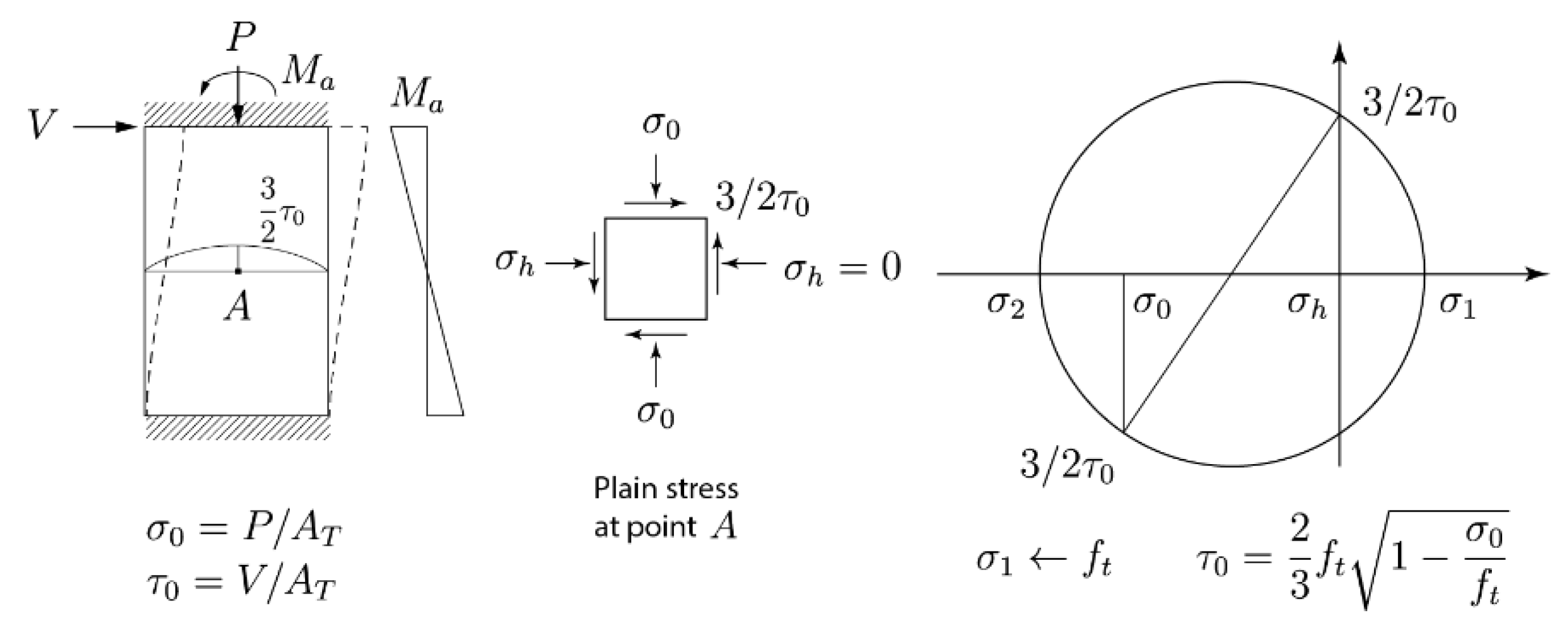
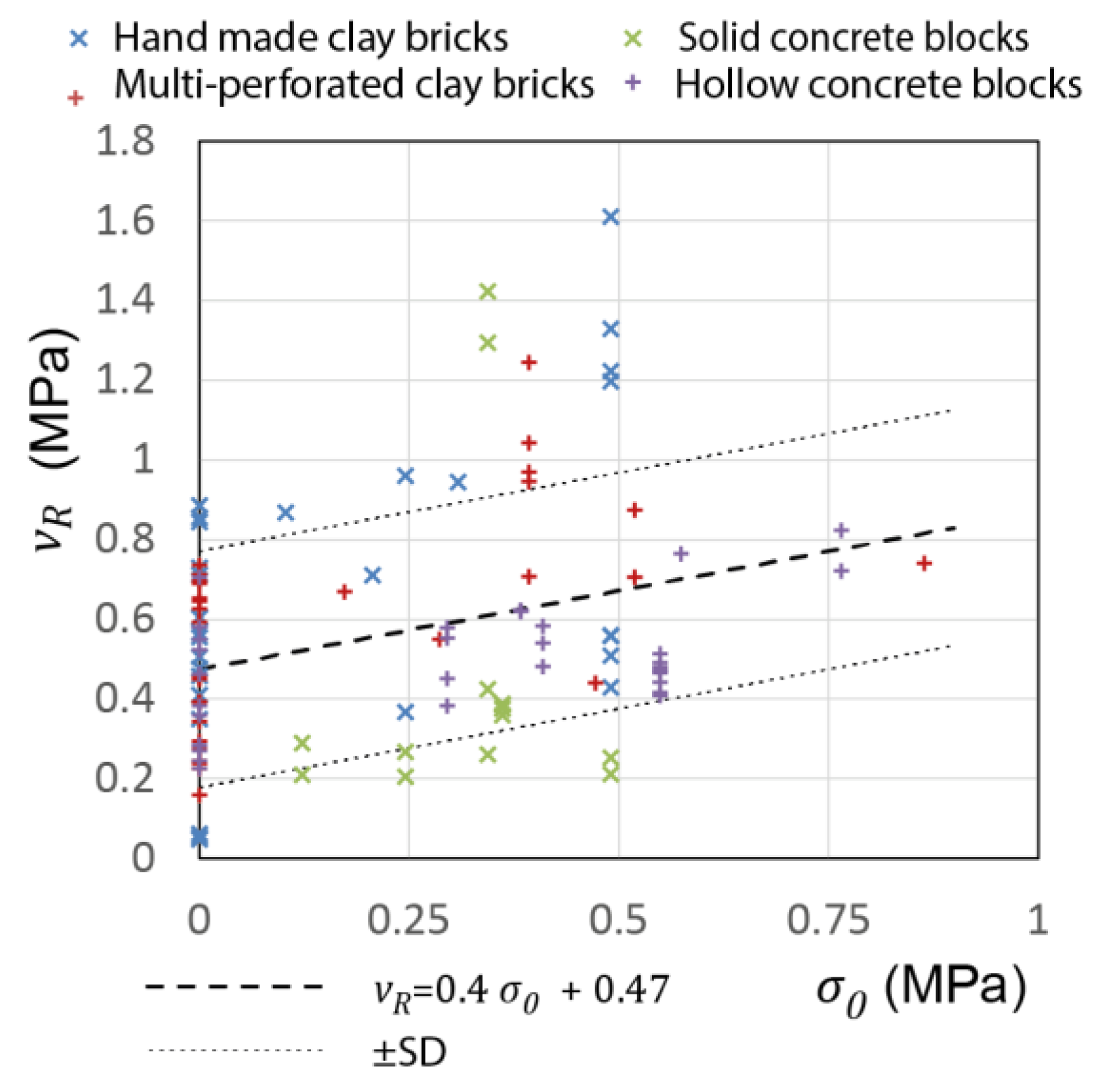
2.1.1. The Effect of Masonry Tensile Strength
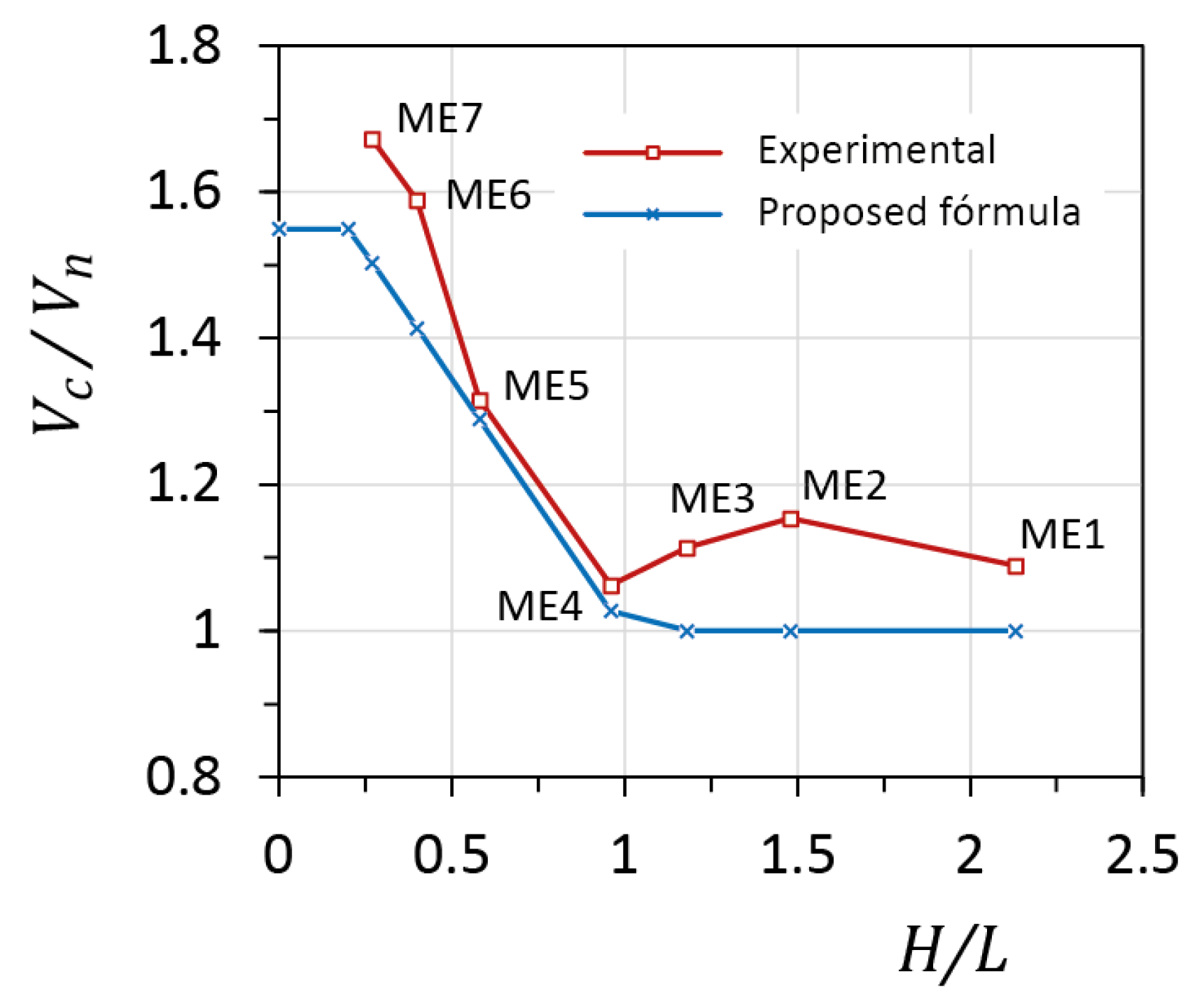
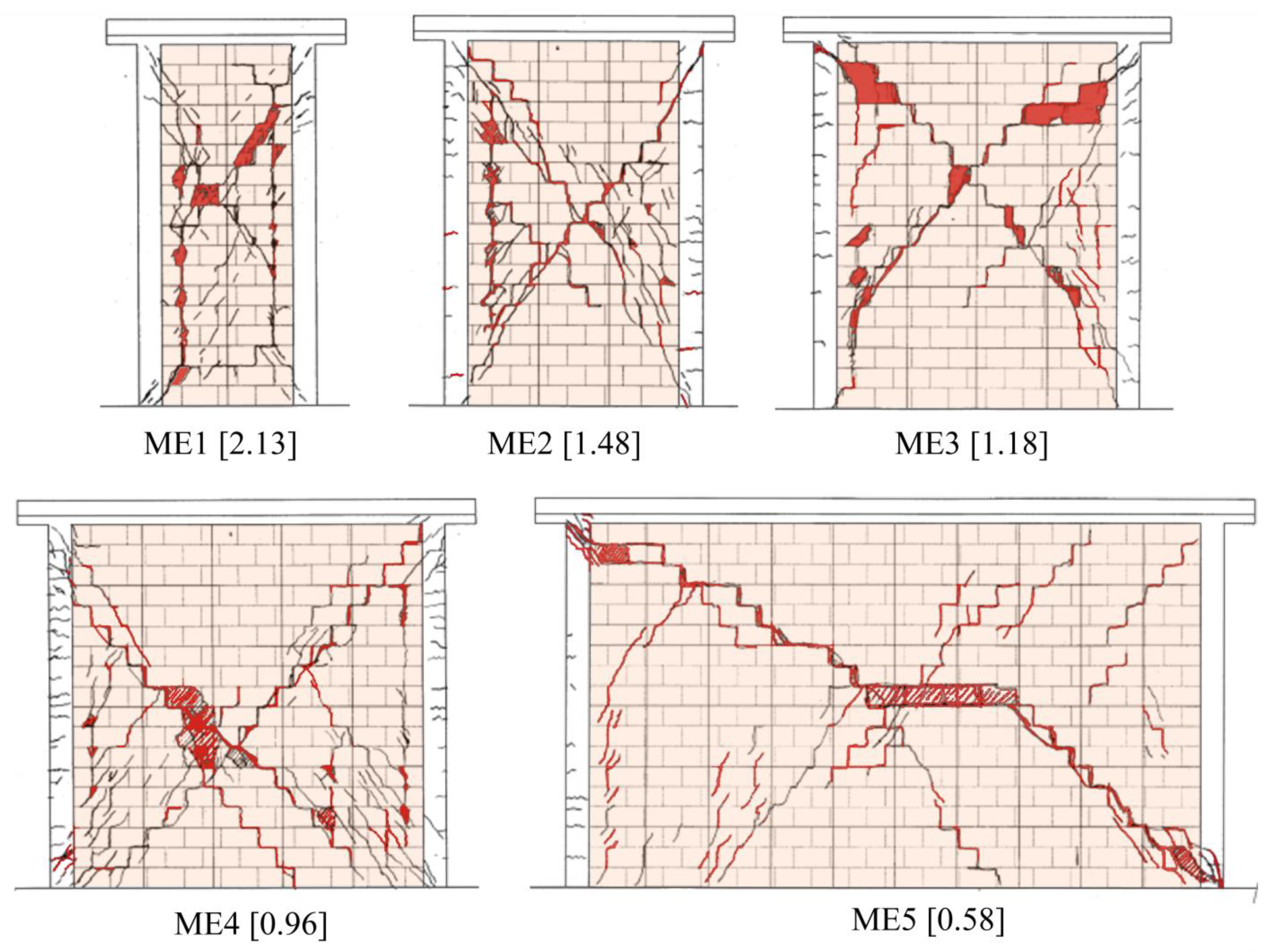
2.1.2. The Effect of Wall Aspect Ratio
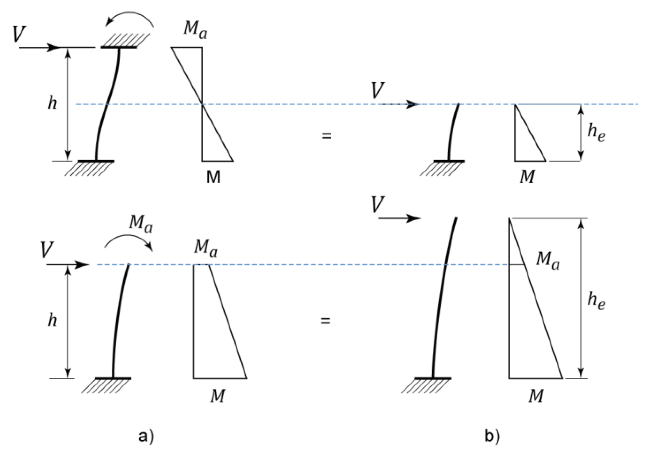
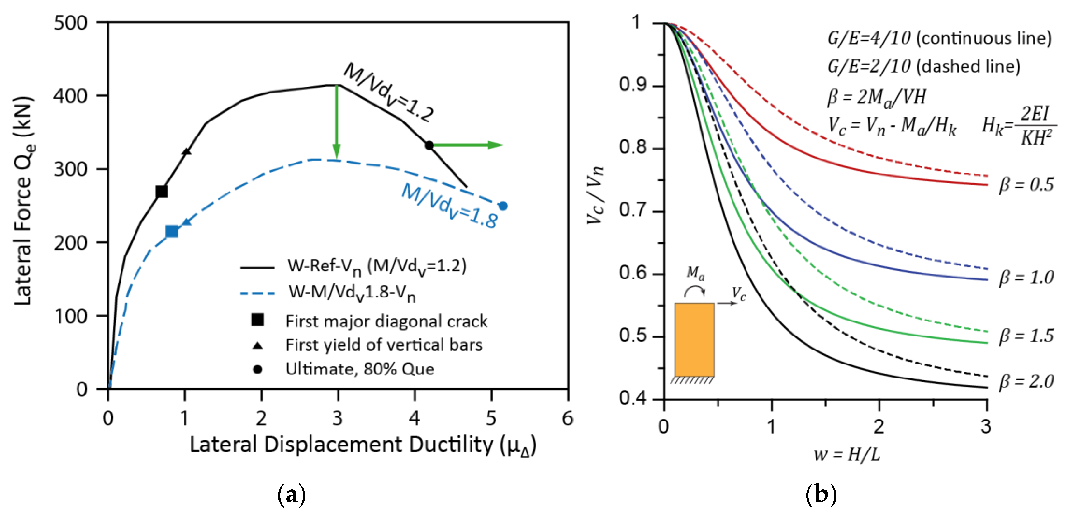
2.1.3. Shear–Moment Interaction
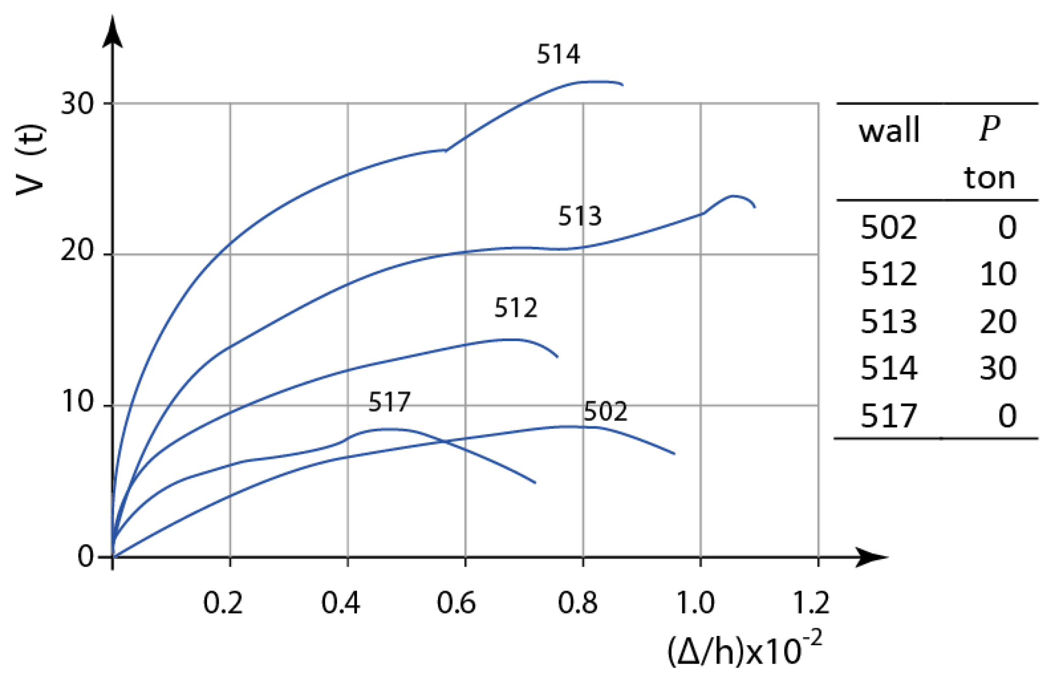
2.2. The Axial Stress Component
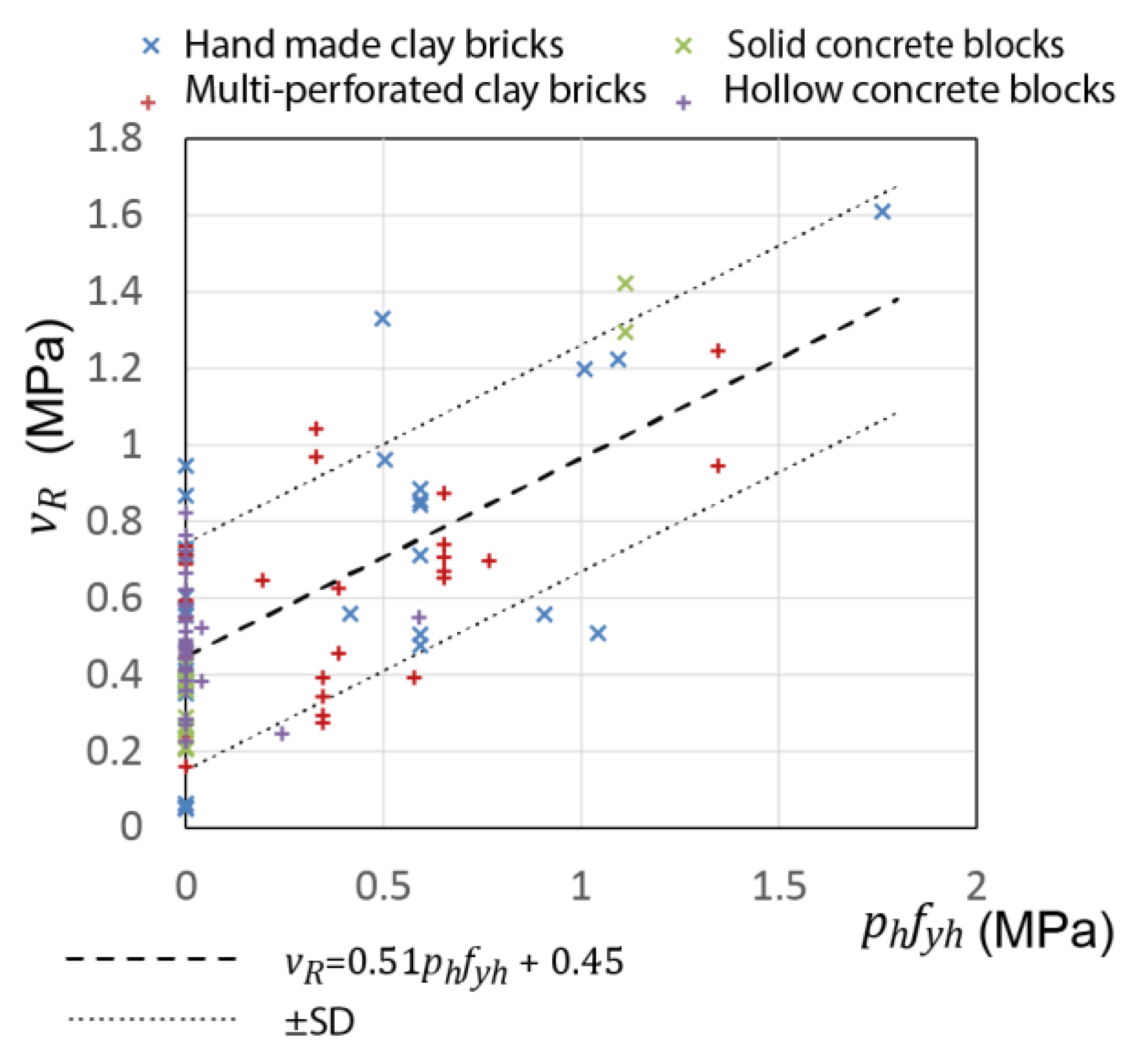
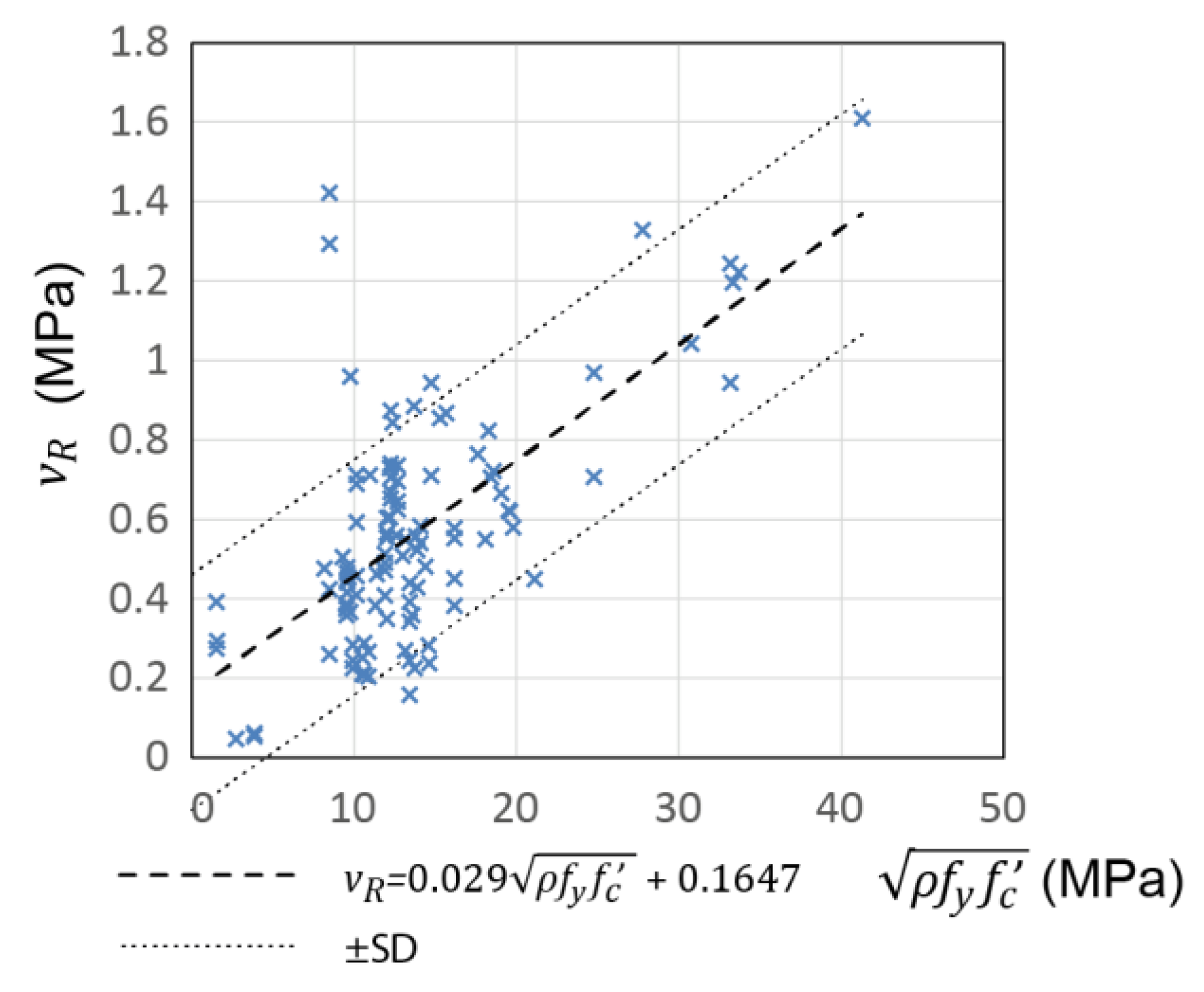
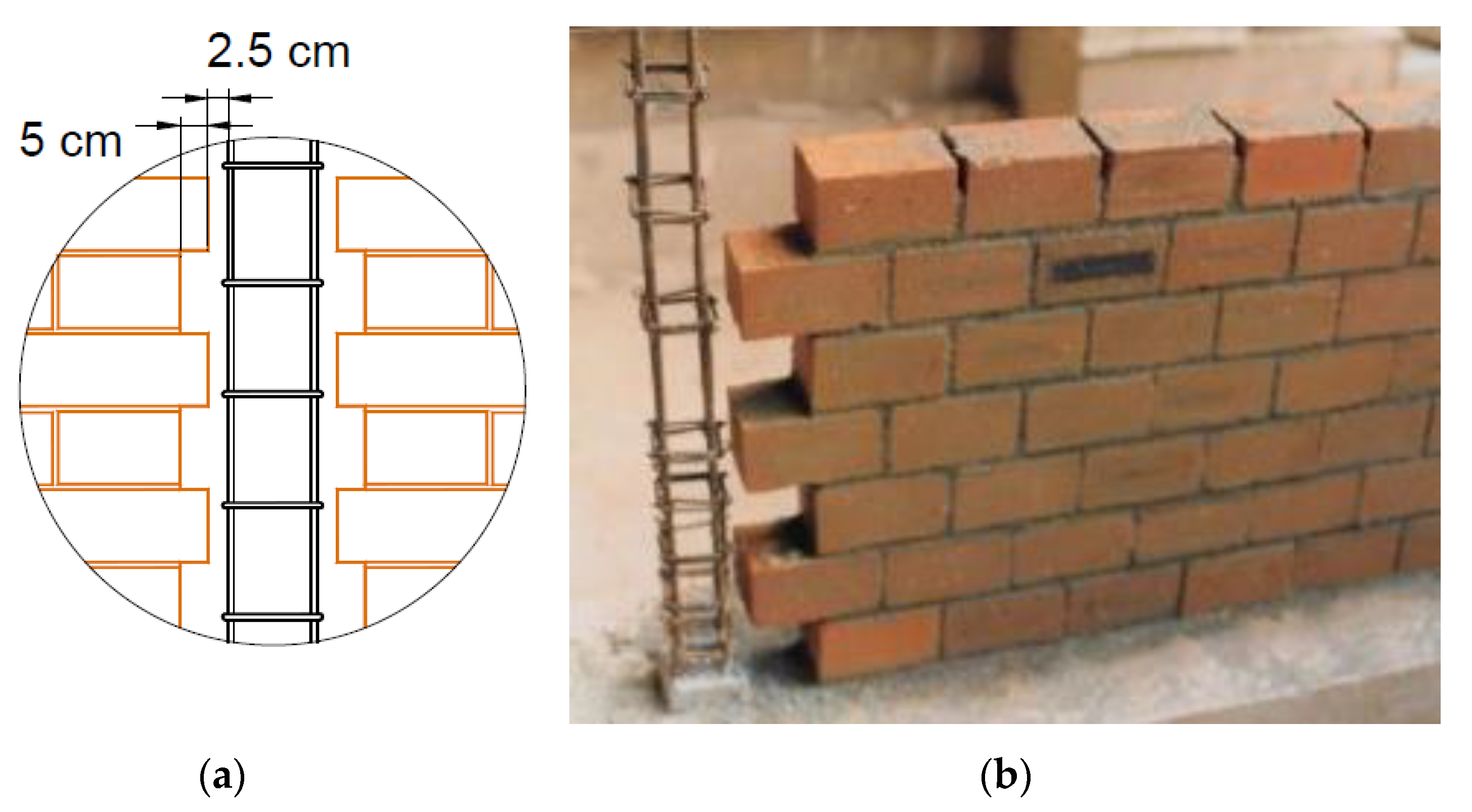
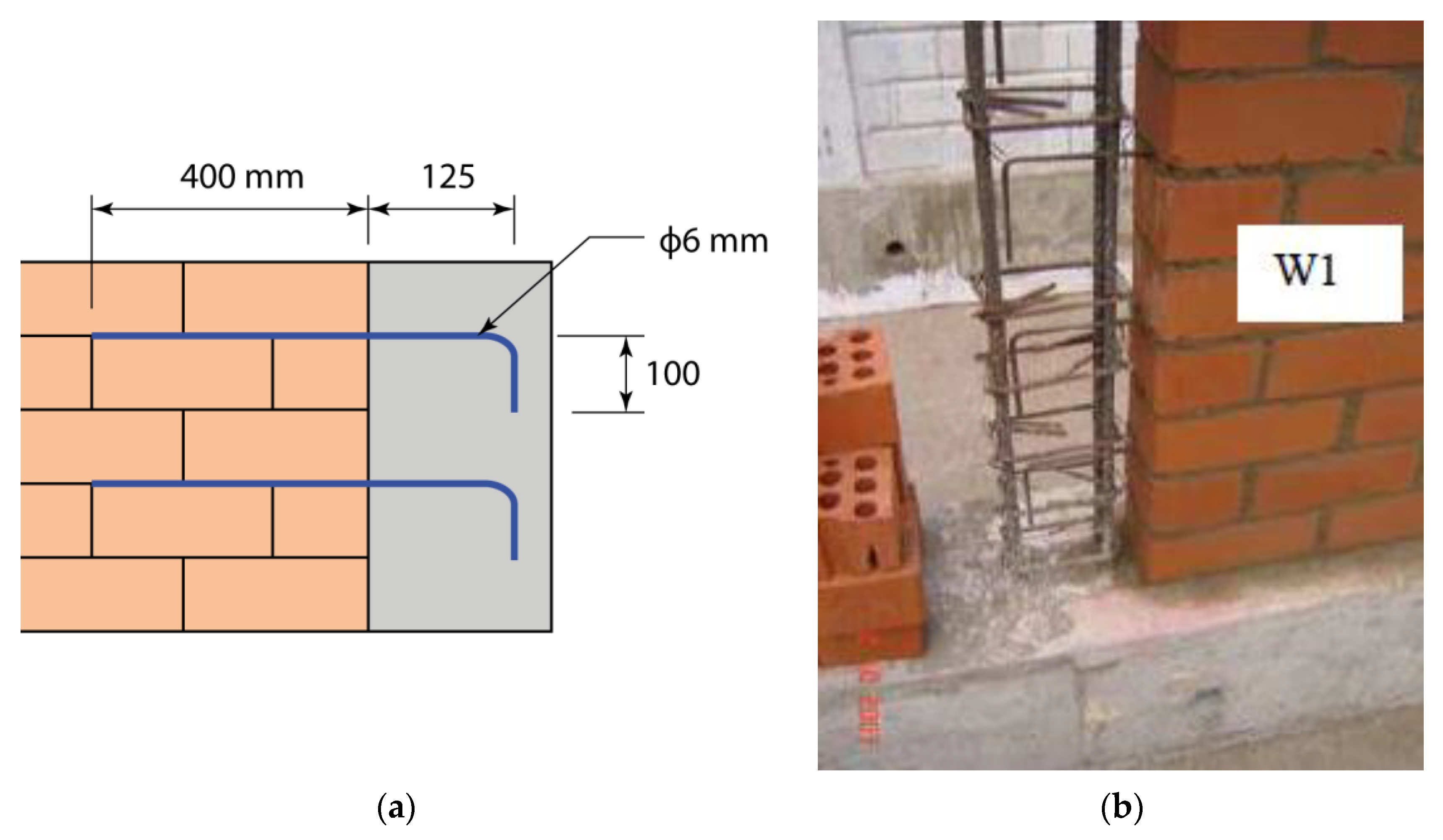
2.3. Contribution of Horizontal Reinforcement
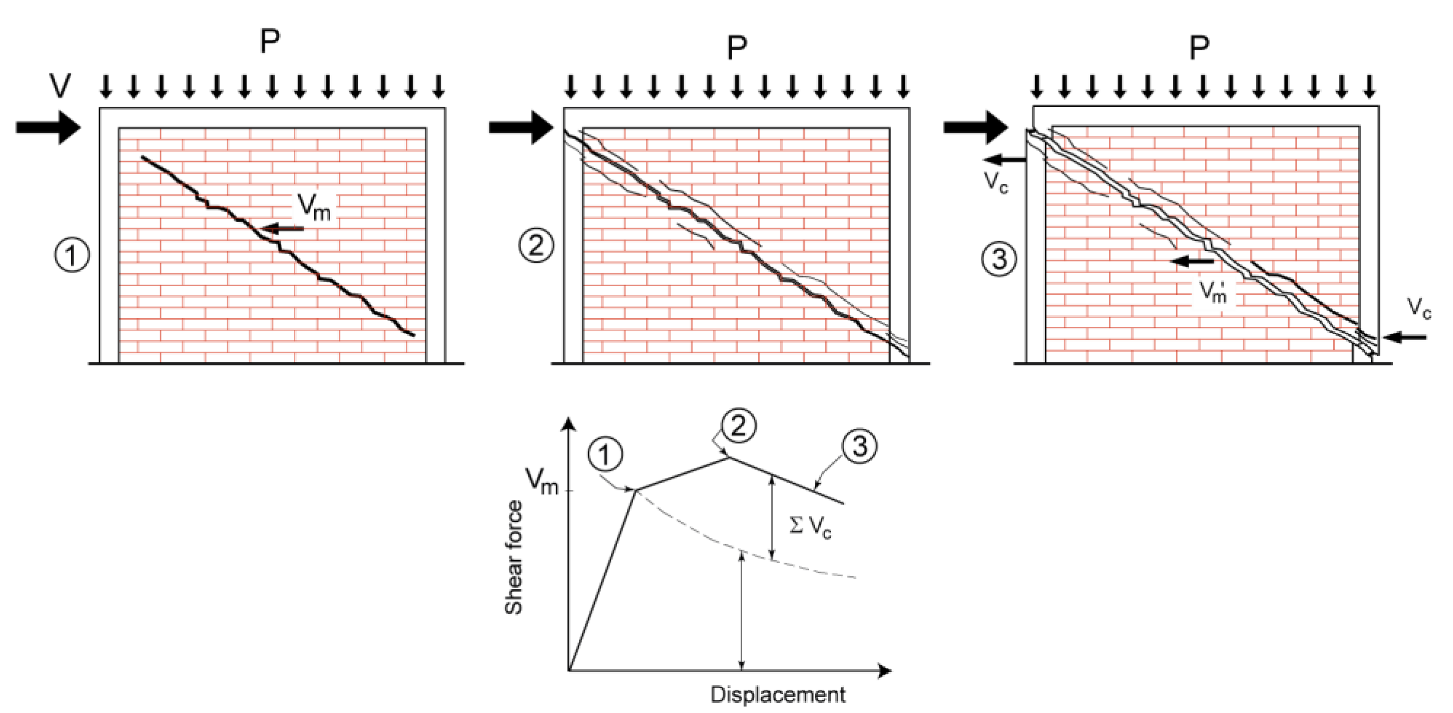
2.4. The Effect of RC Tie-Columns
2.5. Multivariate Model
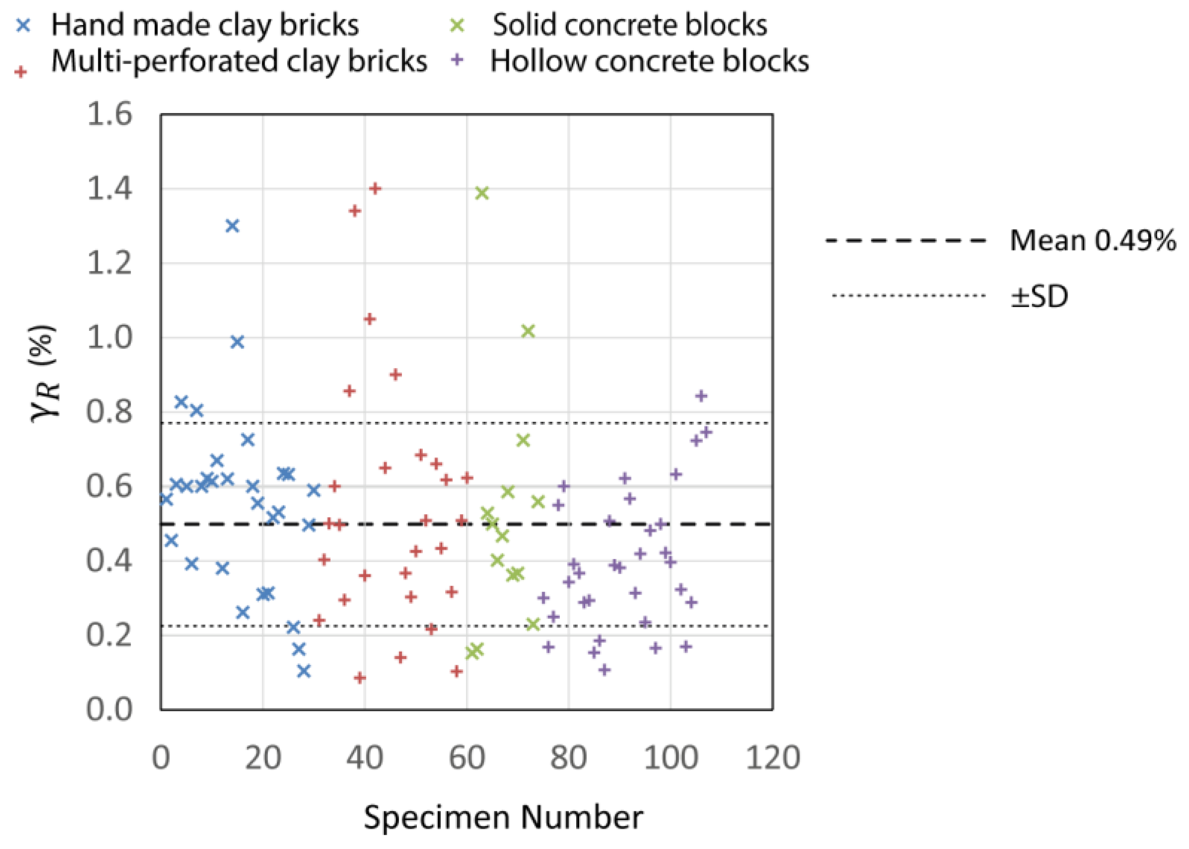
2.6. Lateral Displacement/Drift Capacity
3. Behaviour of CM Walls Subjected to Combined Axial Compression and In-Plane Flexure
3.1. Experimental Research Studies
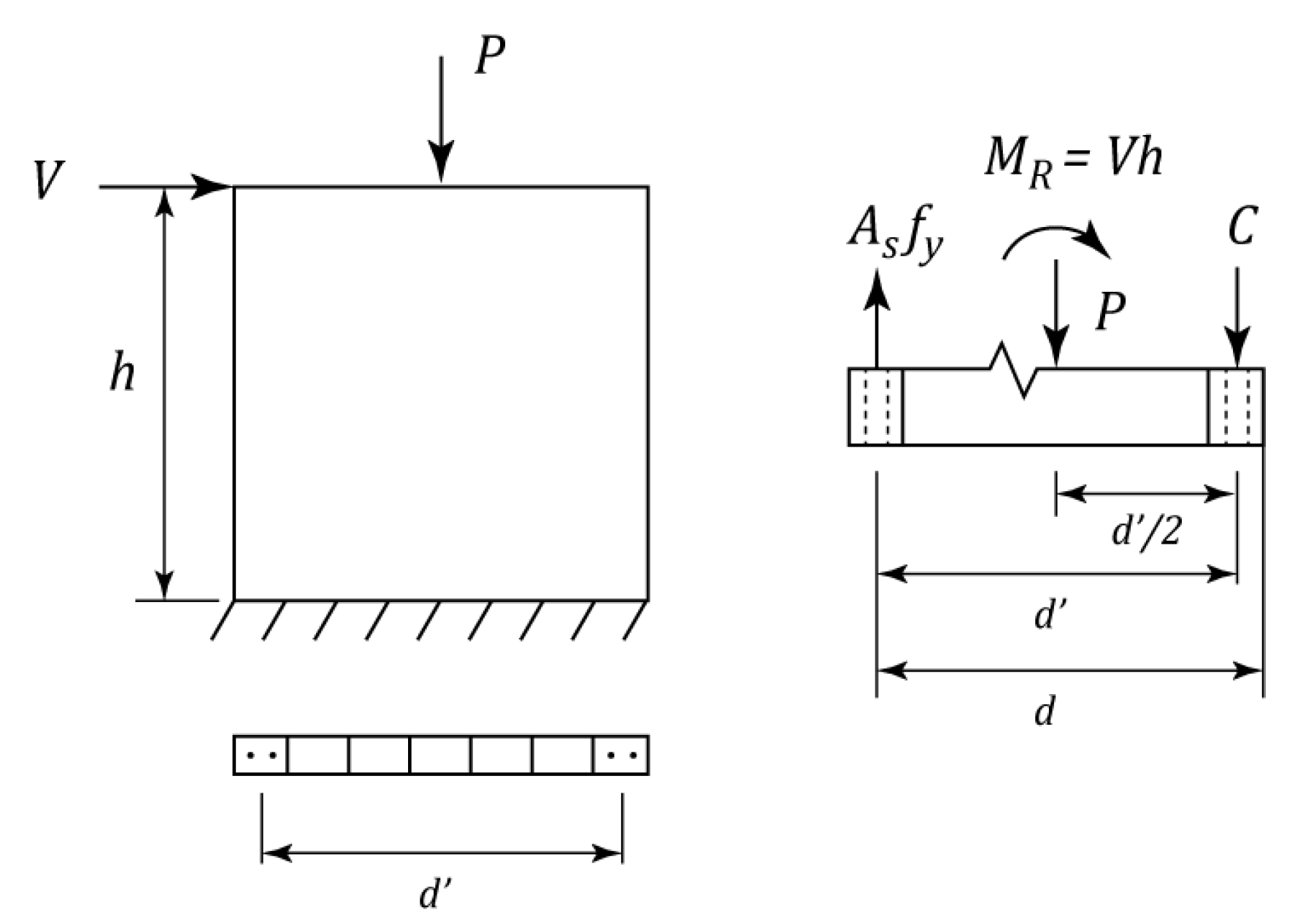
3.2. Estimating the Moment Resistance of CM Walls Subjected to a Combination of Axial Load and Flexure
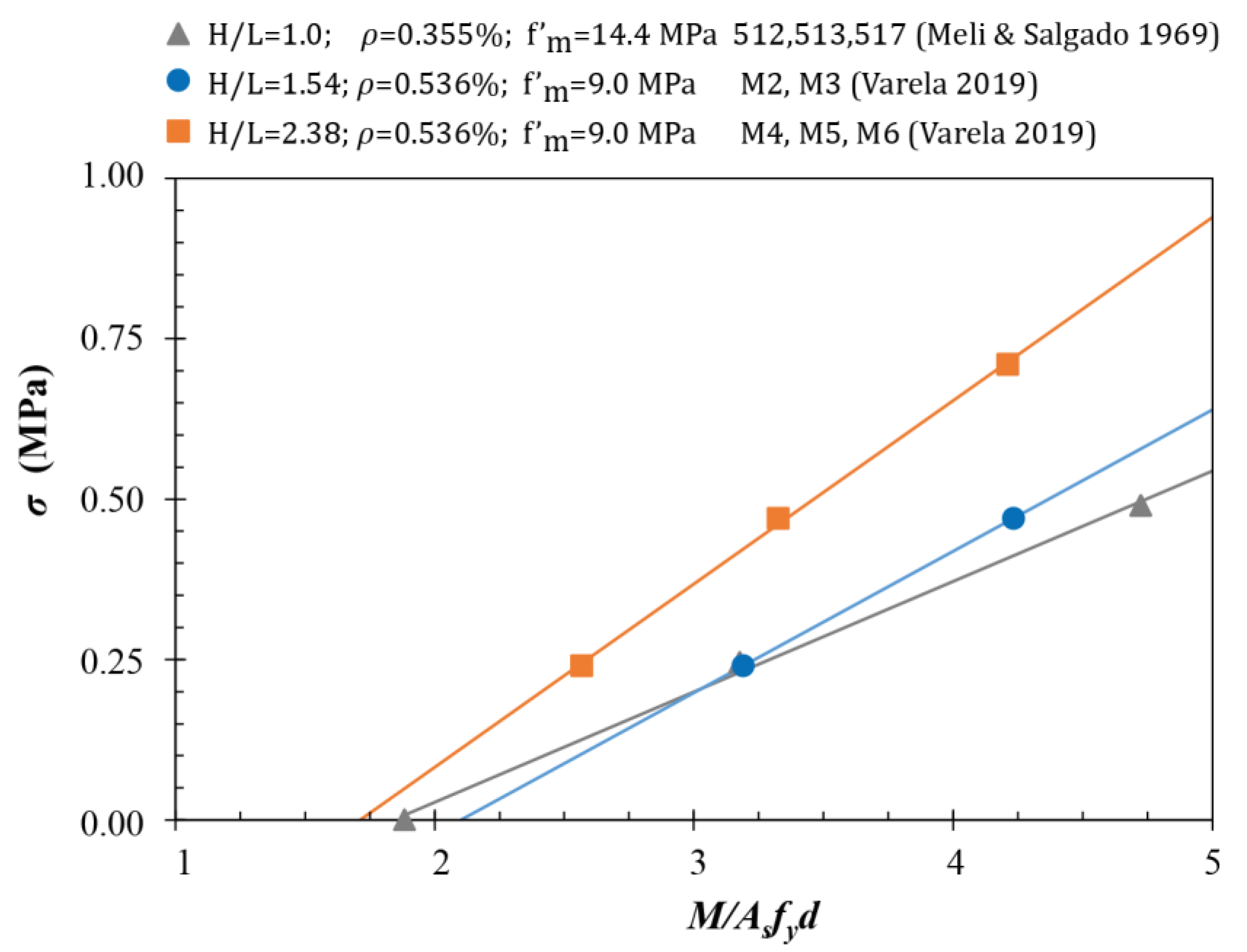
3.3. The Effect of Axial Stress and Wall Aspect Ratio
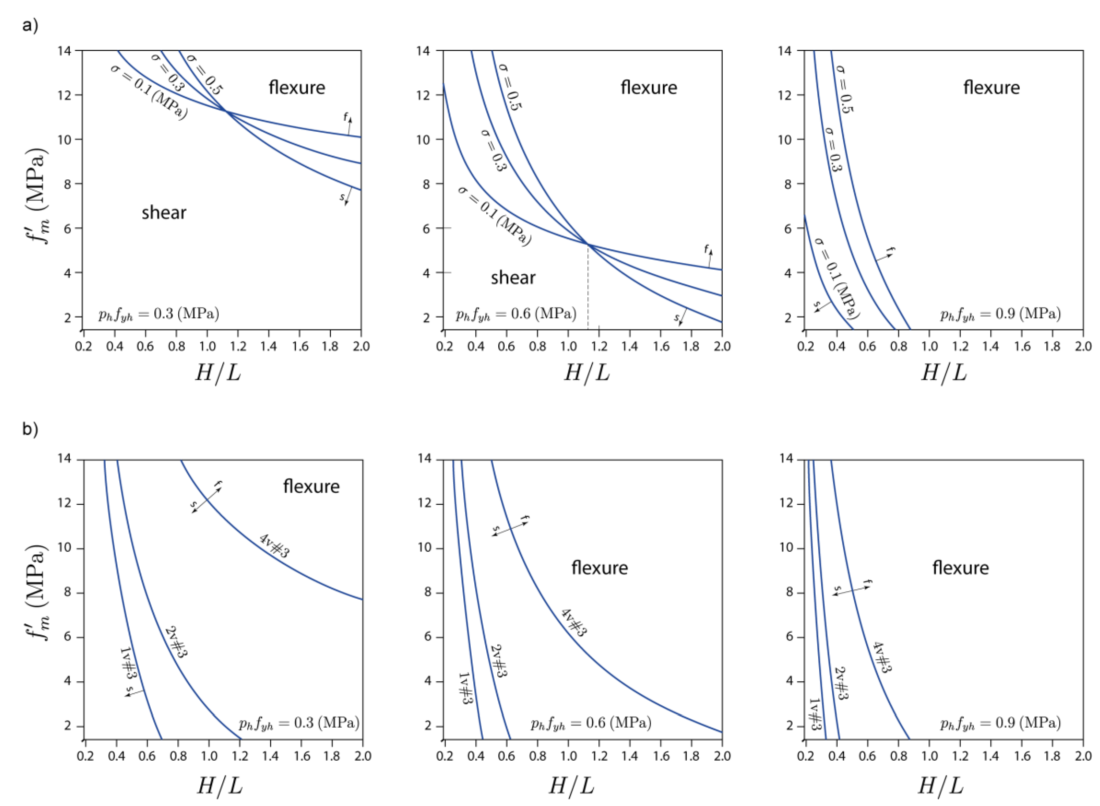
3.4. Key Factors Influencing the Occurrence of Shear- and Flexure-Dominant Failure in CM Walls
4. Behaviour of CM Walls Subjected to Combined Axial Load and OOP Lateral Loading
4.1. Approaches for Estimating the OOP Capacity of CM Walls
4.1.1. Elastic Flexural Theory
4.1.2. Arching Mechanism
4.1.3. Experimental Research Studies
4.2. Effect of Wall Slenderness (h/t) Ratio
4.3. Effect of Wall Aspect Ratio (h/L)
4.4. Effect of Axial Compression
4.5. Effect of the Stiffness of RC Confining Elements
4.6. Difference between Monotonic Static Loading and Dynamic/Seismic Loading
5. Factors Related to the Design and Construction of CM Walls
5.1. Openings in CM Walls
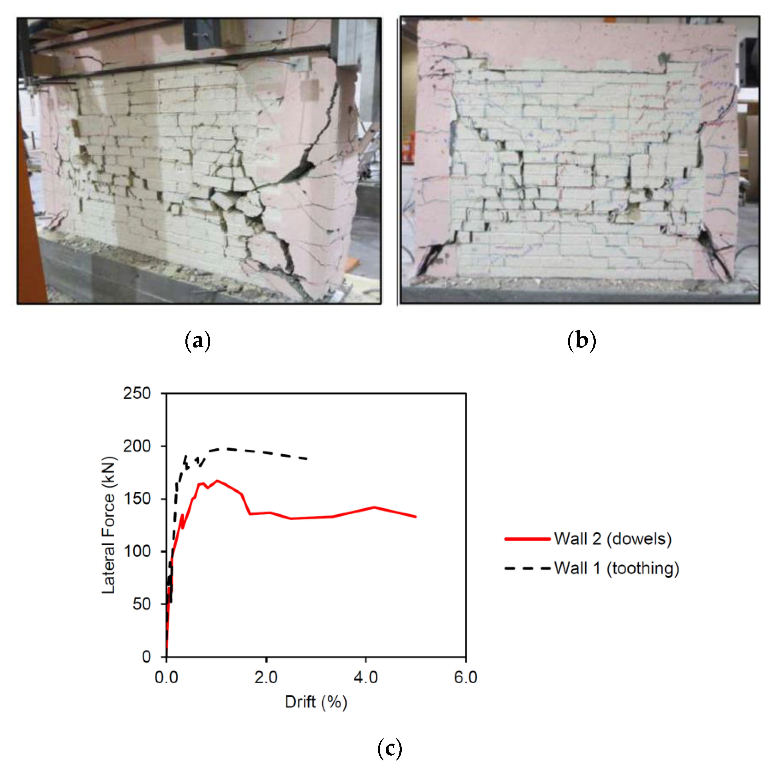
5.2. Toothing
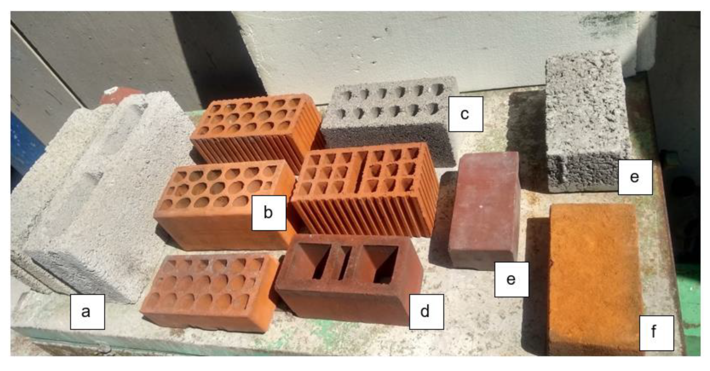
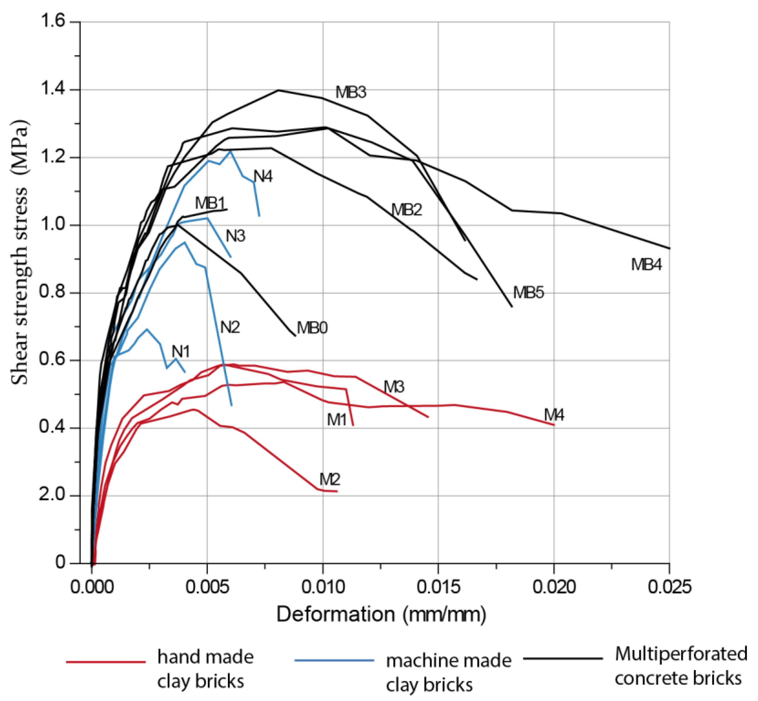
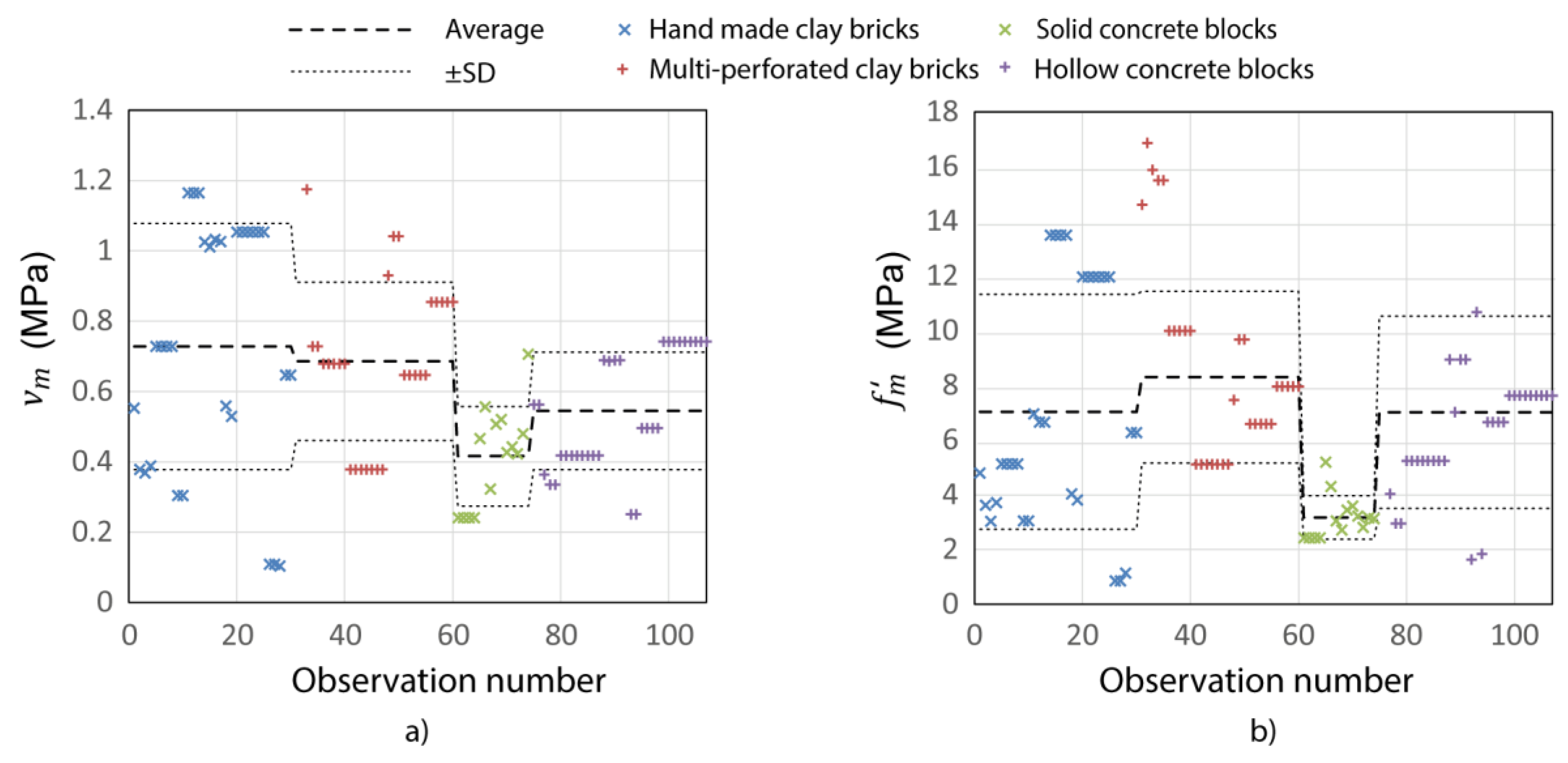
5.3. Materials
6. Conclusions and Research Gaps
6.1. In-Plane Shear
- Shear strength of walls under tension;
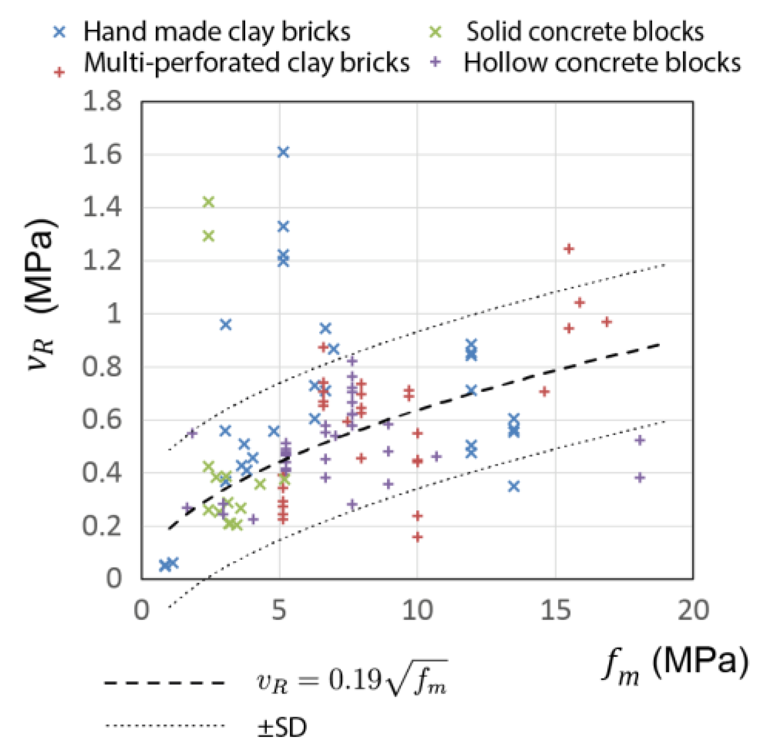
- The effect of the geometry of masonry units on masonry shear strength (bricks vs. blocks, perforated units);
- A rational mechanical model for understanding the shear contribution of horizontal reinforcement; and
- The interaction of in-plane shear and flexure.
6.2. In-Plane Flexure
6.3. Out-of-Plane (OOP) Behaviour
- The OOP response of CM walls constructed using clay bricks and multi-perforated clay blocks;
- The effect of the stiffness of the RC confining elements on the OOP behaviour of CM walls;
- A comparison of the OOP behaviour of masonry infills in RC frames and CM walls under reversed cyclic loading;
- The OOP response of CM walls subjected to reversed cyclic loading, and also dynamic loading (e.g., shaking table tests); and
- The effect of combined in-plane and OOP loading.
6.4. Openings in CM Walls
- The in-plane and OOP behaviour of walls with openings, considering different sizes and locations of openings;
- The effect of the size and location of confining elements in walls with openings; and
- The behaviour of CM walls with openings in buildings with flexible floor/roof diaphragms.
6.5. Toothing
- The toothing length and teeth spacing requirements for CM walls with different types of masonry units (bricks, blocks);
- A comparison of toothing effectiveness for CM walls constructed using brick and block masonry;
- The number (size and spacing) of steel dowels required for CM walls without toothing (a common situation in CM with block units); and
- The response of CM walls with/without toothing under reversed cyclic loading.
6.6. Materials
Author Contributions
Funding
Data Availability Statement
Acknowledgments
Conflicts of Interest
Appendix A. Database of Experimental Test Data Related to CM Walls

| Reference | Country | Number of Walls | Type of Units |
|---|---|---|---|
| Aguilar et al. (2001) [65] | México | 4 | Hand-made clay bricks |
| Pineda (1996) [67] | México | 4 | Hand-made clay bricks |
| Mendoza (2006) [68] | México | 1 | Hand-made clay bricks |
| Vázquez (2005) [69] | México | 1 | Hand-made clay bricks |
| Arias (2005) [70] | México | 1 | Hand-made clay bricks |
| Barragán (2005) [71] | México | 1 | Hand-made clay bricks |
| Diez (1987) [72] | Chile | 4 | Hand-made clay bricks |
| San Bartolomé (1983) [73] | Perú | 2 | Hand-made clay bricks |
| San Bartolomé (-) [74] | Perú | 6 | Hand-made multiperforated clay bricks |
| San Bartolomé et al. (-) [75] | Perú | 3 | Hand-made soil sand and straw |
| González et al. (-) [66] | Perú | 2 | Hand-made clay bricks |
| Zepeda et al. (2001) [76] | México | 4 | Machine-made multiperforated bricks |
| Meli et al. (1969) [13] | México | 5 | Machine-made multiperforated bricks |
| Hernández et al. (1976) [16] | México | 7 | Machine-made multiperforated bricks |
| San Bartolomé (1983) [73] | Perú | 3 | Machine-made multiperforated bricks |
| Echevarría (-) [77] | Perú | 5 | Machine-made multiperforated bricks |
| Pastorutti et al. (-) [78] | Perú | 5 | Machine-made multiperforated bricks |
| Alcocer et al. (2003) [79] | México | 4 | Solid concrete bricks |
| Urzúa (1999) [80] | México | 4 | Solid concrete bricks |
| Cosío (2001) [81] | México | 6 | Solid concrete bricks |
| Meli et al. (1968) [82] | México | 2 | Hollow concrete blocks |
| Hernández et al. (1976) [16] | México | 2 | Hollow concrete blocks |
| Treviño et al. (2004) [83] | México | 8 | Hollow concrete blocks |
| Muñoz (1992) [84] | Chile | 4 | Hollow concrete blocks |
| Ramirez et al. (-) [85] | Perú | 1 | Hollow concrete blocks |
| Quiun et al. (2005) [86] | Perú | 2 | Hollow concrete blocks |
| Marinilli et al. (2007) [87] | Venezuela | 4 | Hollow concrete blocks |
| Castilla (1998) [88] | Venezuela | 9 | Hollow concrete blocks |
| Num | Identification | Unit | Geometry | Masonry | Tie-Column | Shear Strength | ||||||||
|---|---|---|---|---|---|---|---|---|---|---|---|---|---|---|
| Reference | Study ID | Specimen ID | Type (+) | fp (MPa) | L (cm) | H (cm) | t (cm) | fm (MPa) | p (%) | fy (MPa) | f′c (MPa) | Vag+ (kN) | Vmax+ (kN) | |
| 1 | Aguilar et al. (2001) [65] | CEN08 | M-3/8-Z6 | 1 | 11.8 | 250 | 250 | 12.5 | 4.8069 | 1.52% | 447.3 | 27.0 | 147.2 | 174.1 |
| 2 | Aguilar et al. (2001) [65] | CEN09 | M-0-E6 | 1 | 11.8 | 250 | 250 | 12.5 | 3.6297 | 1.51% | 447.3 | 27.5 | 98.1 | 133.9 |
| 3 | Aguilar et al. (2001) [65] | CEN10 | M-5/32-E20 | 1 | 11.8 | 250 | 250 | 12.5 | 3.0411 | 1.51% | 447.3 | 22.6 | 127.5 | 174.6 |
| 4 | Aguilar et al. (2001) [65] | CEN11 | M-1/4-E6 | 1 | 11.8 | 250 | 250 | 12.5 | 3.7278 | 1.51% | 447.3 | 24.0 | 103.0 | 158.9 |
| 5 | Pineda (1996) [67] | CEN12 | M-072 | 1 | 11.8 | 250 | 250 | 12.5 | 5.14044 | 3.17% | 442.4 | 53.0 | 281.1 | 415.5 |
| 6 | Pineda (1996) [67] | CEN13 | M-147 | 1 | 11.8 | 250 | 250 | 12.5 | 5.14044 | 4.56% | 442.4 | 53.0 | 291.4 | 374.3 |
| 7 | Pineda (1996) [67] | CEN14 | M-147R | 1 | 11.8 | 250 | 250 | 12.5 | 5.14044 | 4.56% | 453.2 | 53.0 | 196.7 | 382.1 |
| 8 | Pineda (1996) [67] | CEN15 | M-211 | 1 | 11.8 | 250 | 250 | 12.5 | 5.14044 | 6.84% | 453.2 | 53.0 | 361.0 | 503.3 |
| 9 | Mendoza (2006) [68] | CEN35 | MV-2 | 1 | 10.4 | 230 | 250 | 12 | 3.05091 | 1.58% | 418.0 | 13.9 | 51.6 | 101.5 |
| 10 | Vázquez (2005) [69] | II-MV5 | M1SRCC | 1 | 11.8 | 508.92 | 120 | 6 | 6.9651 | 1.98% | 455.9 | 26.2 | 182.5 | 264.9 |
| 11 | Arias (2005) [70] | II-MV6 | M3SRCC | 1 | 11.8 | 508.92 | 120 | 6 | 6.6708 | 1.98% | 455.9 | 23.2 | 227.6 | 288.4 |
| 12 | Barragán (2005) [71] | II-MV7 | M2SRCC | 1 | 11.8 | 508.92 | 120 | 6 | 6.6708 | 1.98% | 455.9 | 23.2 | 159.9 | 216.8 |
| 13 | Diez (1987) [72] | CHILE4 | MRE1 | 2 | 11.8 | 120 | 240 | 14 | 13.49856 | 1.62% | 412.0 | 20.9 | 58.9 | 101.5 |
| 14 | Diez (1987) [72] | CHILE5 | MRE2 | 2 | 11.8 | 120 | 240 | 14 | 13.49856 | 1.62% | 412.0 | 20.9 | 58.9 | 95.2 |
| 15 | Diez (1987) [72] | CHILE9 | MRG1 | 2 | 11.8 | 240 | 240 | 14 | 13.49856 | 1.62% | 412.0 | 20.9 | 117.7 | 117.7 |
| 16 | Diez (1987) [72] | CHILE1 | MRG2 | 2 | 11.8 | 240 | 240 | 14 | 13.49856 | 1.62% | 412.0 | 20.9 | 155.0 | 186.4 |
| 17 | San Bartolomé (1983) [73] | PERU2 | A-0-1 | 1 | 5.6 | 240 | 240 | 13.5 | 4.04172 | 1.49% | 428.7 | 15.5 | 110.9 | 148.1 |
| 18 | San Bartolomé (1983) [73] | PERU5 | A-1-2 | 1 | 5.6 | 240 | 240 | 13.5 | 3.81609 | 1.49% | 428.7 | 15.5 | 102.7 | 133.0 |
| 19 | San Bartolomé (-) [74] | PERU14 | M1 | 2 | 23.1 | 240 | 250 | 13 | 11.9682 | 1.09% | 445.9 | 17.2 | 115.4 | 157.6 |
| 20 | San Bartolomé (-) [74] | PERU15 | M2 | 2 | 23.1 | 240 | 250 | 13 | 11.9682 | 0.91% | 412.0 | 17.2 | 111.1 | 148.6 |
| 21 | San Bartolomé (-) [74] | PERU16 | M3 | 2 | 23.1 | 240 | 250 | 13 | 11.9682 | 1.94% | 443.6 | 17.2 | 176.6 | 263.3 |
| 22 | San Bartolomé (-) [74] | PERU17 | M4 | 2 | 23.1 | 240 | 250 | 13 | 11.9682 | 1.64% | 412.0 | 17.2 | 176.6 | 222.0 |
| 23 | San Bartolomé (-) [74] | PERU18 | M5 | 2 | 23.1 | 240 | 250 | 13 | 11.9682 | 3.05% | 429.9 | 17.2 | 176.6 | 266.9 |
| 24 | San Bartolomé (-) [74] | PERU19 | M6 | 2 | 23.1 | 240 | 250 | 13 | 11.9682 | 2.55% | 412.0 | 17.2 | 176.6 | 276.1 |
| 25 | San Bartolomé et al. (-) [75] | PERU20 | M1 | 1 | 5.9 | 274 | 245 | 25 | 0.861318 | 0.34% | 418.2 | 10.2 | 36.7 | 37.2 |
| 26 | San Bartolomé et al. (-) [75] | PERU21 | M2 | 1 | 5.9 | 274 | 245 | 25 | 0.861318 | 0.17% | 418.2 | 10.2 | 33.7 | 33.2 |
| 27 | San Bartolomé et al. (-) [75] | PERU22 | M3 | 1 | 5.9 | 274 | 245 | 25 | 1.141884 | 0.34% | 418.2 | 10.2 | 42.3 | 42.9 |
| 28 | González et al. (-) [66] | PERU23 | M1 | 2 | 9.8 | 240 | 230 | 13 | 6.2784 | 1.95% | 412.0 | 17.9 | 113.0 | 227.7 |
| 29 | González et al. (-) [66] | PERU24 | M2 | 2 | 9.8 | 240 | 230 | 13 | 6.2784 | 1.95% | 412.0 | 17.9 | 123.3 | 188.8 |
| 30 | Zepeda et al. (2001) [76] | CEN16 | N1 | 2 | 22.0 | 240 | 230 | 12 | 14.6169 | 4.95% | 459.1 | 26.0 | 180.0 | 203.6 |
| 31 | Zepeda et al. (2001) [76] | CEN17 | N2 | 2 | 22.0 | 240 | 230 | 12 | 16.8732 | 4.95% | 459.1 | 26.0 | 172.7 | 279.1 |
| 32 | Zepeda et al. (2001) [76] | CEN18 | N3 | 2 | 22.0 | 240 | 230 | 12 | 15.8922 | 6.33% | 451.3 | 31.9 | 192.3 | 300.2 |
| 33 | Zepeda et al. (2001) [76] | CEN19 | N4 | 2 | 22.0 | 240 | 230 | 12 | 15.4998 | 8.71% | 467.1 | 26.0 | 175.6 | 358.6 |
| Study | Specimen | Unit | H (mm) | L (mm) | H/L | t (mm) | H/t | Axial Stress (MPa) | fm (MPa) | # of Supports | Wcr (kPa) | Wu (kPa) |
|---|---|---|---|---|---|---|---|---|---|---|---|---|
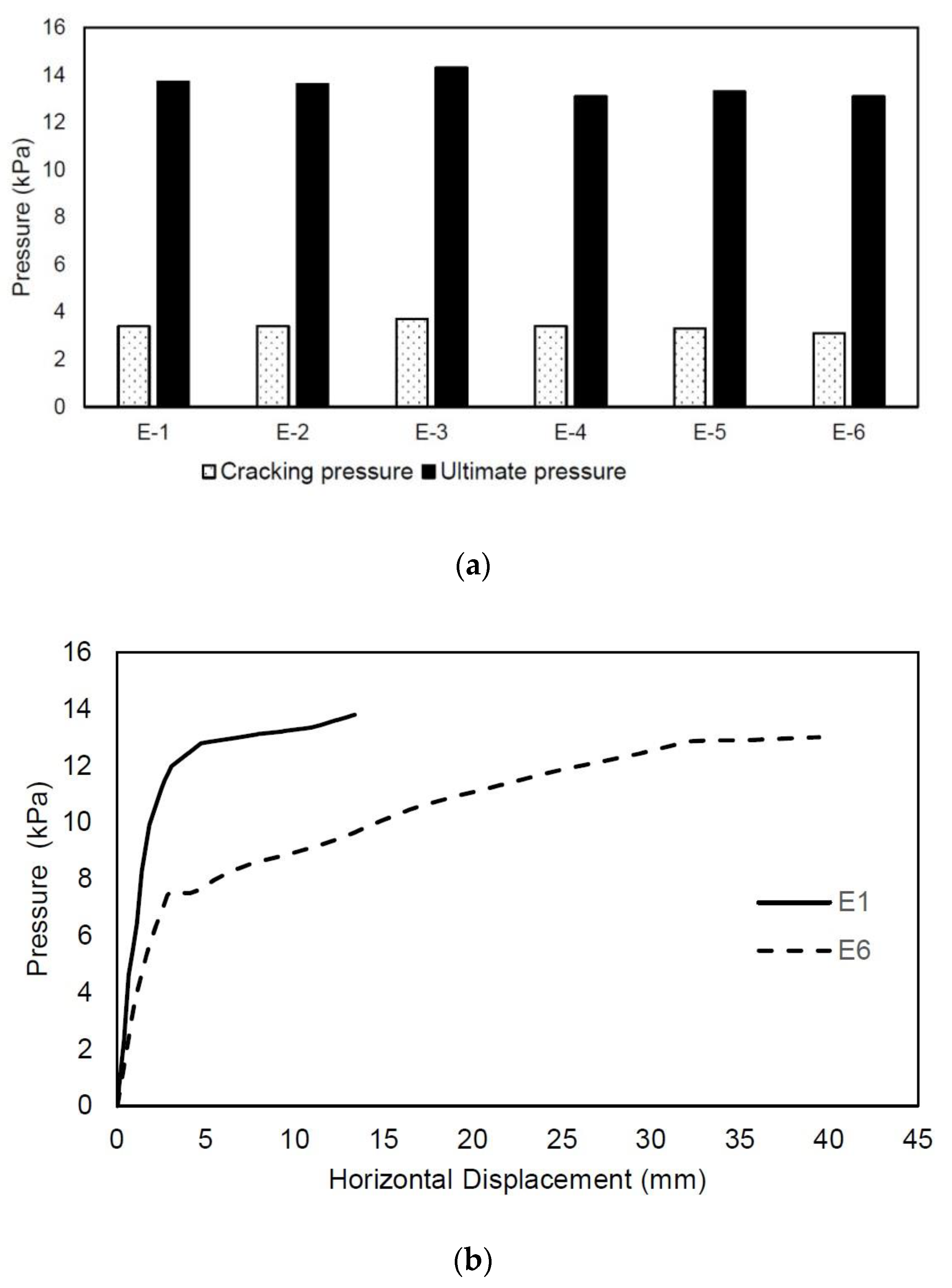
| Varela-Rivera et al. (2011) [129] | E-1 | HCB | 1760 | 3600 | 0.49 | 150 | 11.73 | 3.07 | 4 | 3.4 | 13.7 | |
| E-2 | HCB | 1760 | 3600 | 0.49 | 150 | 11.73 | 3.07 | 4 | 3.4 | 13.6 | ||
| E-3 | HCB | 1760 | 3600 | 0.49 | 150 | 11.73 | 3.07 | 4 | 3.7 | 14.3 | ||
| E-4 | HCB | 1760 | 3600 | 0.49 | 150 | 11.73 | 3.07 | 3 | 3.4 | 13.1 | ||
| E-5 | HCB | 1760 | 3600 | 0.49 | 150 | 11.73 | 3.07 | 3 | 3.3 | 13.3 | ||
| E-6 | HCB | 1760 | 3600 | 0.49 | 150 | 11.73 | 3.07 | 3 | 3.1 | 13.1 | ||
| Varela-Rivera, Moreno-Herrera, et al. (2012) [50] | E-1 | HCB | 2720 | 3670 | 0.74 | 150 | 18.13 | 2.84 | 4 | 2.63 | 8.79 | |
| E-2 | HCB | 2880 | 3770 | 0.76 | 150 | 19.20 | 2.84 | 4 | 6.37 | 13.01 | ||
| E-3 | HCB | 2880 | 3770 | 0.76 | 120 | 24.00 | 2.85 | 4 | 4.81 | 12.01 | ||
| E-4 | HCB | 2720 | 2850 | 0.95 | 150 | 18.13 | 2.84 | 4 | 5.1 | 14.53 | ||
| E-5 | HCB | 2720 | 2950 | 0.92 | 150 | 18.13 | 2.84 | 4 | 5.1 | 17.83 | ||
| E-6 | HCB | 2720 | 2950 | 0.92 | 120 | 22.67 | 2.85 | 4 | 4.03 | 15.4 | ||
| Varela-Rivera, Polanco-May, et al. (2012) [130] | S-1 | HCB | 2700 | 3700 | 0.73 | 150 | 18 | 0.000 | 2.840 | 4 | 2.63 | 8.79 |
| S-2 | HCB | 2700 | 3700 | 0.73 | 150 | 18 | 0.065 | 2.640 | 4 | 4.26 | 17.32 | |
| S-3 | HCB | 2700 | 3700 | 0.73 | 150 | 18 | 0.196 | 2.640 | 4 | 6.22 | 18.91 | |
| Moreno-Hererra et al. (2015) [133] | W1 | HCB2 | 2760 | 3770 | 0.73 | 113 | 24.42 | 0.079 | 3.72 | 4 | 8.81 | |
| W2 | MPB | 2760 | 3770 | 0.73 | 115 | 24.00 | 0.082 | 6.48 | 4 | 10.49 | ||
| W3 | MPB | 2760 | 3770 | 0.73 | 120 | 23.00 | 0.079 | 6.17 | 4 | 11.06 | ||
| W4 | SB | 2760 | 3770 | 0.73 | 114 | 24.21 | 0.081 | 4.15 | 4 | 7.33 | ||
| W5 | HCB2 | 2760 | 2950 | 0.94 | 113 | 24.42 | 0.088 | 3.72 | 4 | 13.44 | ||
| W6 | MPB | 2760 | 2950 | 0.94 | 115 | 24.00 | 0.092 | 6.48 | 4 | 17.61 | ||
| W7 | MPB | 2760 | 2950 | 0.94 | 120 | 23.00 | 0.078 | 6.17 | 4 | 18.06 | ||
| W8 | SB | 2760 | 2950 | 0.94 | 114 | 24.21 | 0.085 | 4.15 | 4 | 14.24 | ||
| Navarrete-Marcias et al. (2016) [134] | M1 | HCB | 2550 | 3490 | 0.73 | 120 | 21.25 | 0.11 | 6.48 | 1 | - | 10.95 |
| M2 | HCB | 2550 | 3490 | 0.73 | 120 | 21.25 | 0.23 | 6.48 | 1 | - | 11.22 | |
| M3 | HCB | 2550 | 3490 | 0.73 | 120 | 21.25 | 0.35 | 6.48 | 1 | - | 14.07 | |
| M4 | HCB | 2550 | 2450 | 1.04 | 120 | 21.25 | 0.23 | 6.48 | 1 | - | 9.96 | |
| M5 | HCB | 2550 | 1410 | 1.81 | 120 | 21.25 | 0.23 | 6.48 | 1 | - | 8.43 | |
| Varela-Rivera et al. (2020) [131] | M1 | HCB | 2710 | 1930 | 1.40 | 145 | 18.69 | 0 | 3.3 | 4 | 19.72 | |
| M2 | HCB | 2710 | 1330 | 1.40 | 145 | 18.69 | 0.33 | 3.3 | 4 | 24.23 | ||
| M3 | HCB | 2710 | 1930 | 2.04 | 145 | 18.69 | 0.0 | 3.3 | 4 | 31.64 | ||
| M4 | HCB | 2710 | 1330 | 2.04 | 145 | 18.69 | 0.33 | 3.3 | 4 | 38.32 |
| Study | Specimen | Peak Strength (kN) | H/Href | Opening Length Lop (m) | Opening Height Hop (m) | Panel Length L (m) | Net Panel Length Ln (m) | Panel Height Hw (m) | Opening Area Ao (m2) | Panel Area Ap (m2) | Ar Ratio | B Ratio |
|---|---|---|---|---|---|---|---|---|---|---|---|---|
| Yanez et al. (2004) [138] | Concrete Pattern 1 | 123.25 | 1.00 | 0.00 | 0.00 | 3.65 | 3.65 | 2.25 | 0.00 | 8.21 | 0.00 | 1.00 |
| Concrete Pattern 2 | 78.00 | 0.63 | 2.06 | 1.23 | 3.65 | 1.59 | 2.25 | 2.54 | 8.21 | 0.31 | 0.43 | |
| Concrete Pattern 3 | 120.75 | 0.98 | 0.83 | 1.23 | 3.65 | 2.83 | 2.25 | 1.01 | 8.21 | 0.12 | 0.77 | |
| Concrete Pattern 4 | 101.75 | 0.83 | 0.65 | 2.05 | 3.65 | 3.01 | 2.25 | 1.32 | 8.21 | 0.16 | 0.82 | |
| Brick Pattern 1 | 176.50 | 1.00 | 0.00 | 0.00 | 3.65 | 3.65 | 2.25 | 0.00 | 8.21 | 0.00 | 1.00 | |
| Brick Pattern 2 | 92.00 | 0.52 | 2.05 | 1.13 | 3.65 | 1.60 | 2.25 | 2.31 | 8.21 | 0.28 | 0.44 | |
| Brick Pattern 3 | 146.25 | 0.83 | 0.79 | 1.13 | 3.65 | 2.87 | 2.25 | 0.88 | 8.21 | 0.11 | 0.78 | |
| Brick Pattern 4 | 125.00 | 0.71 | 0.48 | 2.00 | 3.65 | 3.17 | 2.25 | 0.96 | 8.21 | 0.12 | 0.87 | |
| Singhal and Rai (2018) [141] | SI | 84.25 | 1.00 | 0.00 | 0.00 | 2.50 | 2.50 | 1.50 | 0.00 | 3.75 | 0.00 | 1.00 |
| SI-O2WA | 52.40 | 0.62 | 1.02 | 0.62 | 2.50 | 1.48 | 1.50 | 0.63 | 3.75 | 0.17 | 0.59 | |
| SC-OW2B | 75.35 | 0.89 | 1.00 | 0.62 | 2.50 | 1.50 | 1.50 | 0.62 | 3.75 | 0.17 | 0.60 | |
| SC-OW2C | 94.10 | 1.12 | 1.06 | 0.62 | 2.50 | 1.44 | 1.50 | 0.66 | 3.75 | 0.18 | 0.58 | |
| SC-ODWB | 63.85 | 0.76 | 0.50 | 1.10 | 2.50 | 2.00 | 1.50 | 0.55 | 3.75 | 0.15 | 0.80 | |
| Okail (2016) [155] | CLY S-CTRL | 230.00 | 1.00 | 0.00 | 0.00 | 2.31 | 2.31 | 2.28 | 0.00 | 5.27 | 0.00 | 1.00 |
| CLY P-W | 190.00 | 0.83 | 0.53 | 0.71 | 2.31 | 1.78 | 2.28 | 0.38 | 5.27 | 0.07 | 0.77 | |
| CLY P-D | 130.00 | 0.57 | 0.53 | 1.69 | 2.31 | 1.78 | 2.28 | 0.90 | 5.27 | 0.17 | 0.77 | |
| Qin (2021) [143] | S1 | 466.28 | 1.00 | 0.00 | 0.00 | 3.40 | 3.40 | 2.90 | 0.00 | 9.86 | 0.00 | 1.00 |
| O1 | 352.21 | 0.76 | 1.00 | 1.55 | 3.40 | 2.40 | 2.90 | 1.55 | 9.86 | 0.16 | 0.71 | |
| O2 | 274.76 | 0.59 | 1.50 | 1.55 | 3.40 | 1.90 | 2.90 | 2.33 | 9.86 | 0.24 | 0.56 | |
| O3 | 360.76 | 0.77 | 1.00 | 2.10 | 3.40 | 2.40 | 2.90 | 2.10 | 9.86 | 0.21 | 0.71 | |
| Kuroki (2012) [139] | CMWO-07 | 79.70 | 1.00 | 0.00 | 0.00 | 1.70 | 1.70 | 1.51 | 0.00 | 2.57 | 0.00 | 1.00 |
| CMWO-05 | 63.72 | 0.80 | 0.43 | 0.56 | 1.70 | 1.27 | 1.51 | 0.24 | 2.57 | 0.09 | 0.74 | |
| CMWO-06 | 150.02 | 1.88 | 0.43 | 0.56 | 1.70 | 1.27 | 1.51 | 0.24 | 2.57 | 0.09 | 0.74 | |
| CMWO-08 | 108.67 | 1.36 | 0.43 | 0.56 | 1.70 | 1.27 | 1.51 | 0.24 | 2.57 | 0.09 | 0.74 | |
| CMWO-09 | 52.75 | 0.66 | 0.43 | 0.56 | 1.70 | 1.27 | 1.51 | 0.24 | 2.57 | 0.09 | 0.74 | |
| CMWO-10 | 97.44 | 1.22 | 0.43 | 0.56 | 1.70 | 1.27 | 1.51 | 0.24 | 2.57 | 0.09 | 0.74 | |
| CMWO-11 | 49.13 | 0.62 | 0.43 | 1.20 | 1.70 | 1.27 | 1.51 | 0.52 | 2.57 | 0.20 | 0.74 | |
| CMWO-12 | 82.24 | 1.03 | 0.43 | 1.20 | 1.70 | 1.27 | 1.51 | 0.52 | 2.57 | 0.20 | 0.74 | |
| CMWO-13 | 47.40 | 0.59 | 0.43 | 1.20 | 1.70 | 1.27 | 1.51 | 0.52 | 2.57 | 0.20 | 0.74 | |
| CMWO-14 | 78.61 | 0.99 | 0.43 | 1.20 | 1.70 | 1.27 | 1.51 | 0.52 | 2.57 | 0.20 | 0.74 |
| Study | Type of Connection | # of Specimen | H/L | Masonry Unit | In Plane Test | OPP Testing Included | |
|---|---|---|---|---|---|---|---|
| Max Drift (%) | Failure Mechanism | ||||||
| Vegas (1992) [145] | Toothing | 1 | 1.2 | Clay Brick 1/3 | 1.0 | Shear | No |
| Dowels | 1 | 1.2 | Clay Brick 1/3 | 1.0 | Shear | ||
| None | 1 | 1.2 | Clay Brick 1/3 | 1.0 | Shear | ||
| San Bartolomé, Vegas, and Silva (1991) [146] | Dowels | 1 | 1.2 | Clay Brick 1/3 | not available | OOP | Yes |
| None | 1 | 1.2 | Clay Brick 1/3 | not available | OOP | ||
| Gonzalez (1993) [66] | Toothing | 1 | 1 | Clay Brick | 0.65 | Shear | Yes |
| Dowels | 1 | 1 | Clay Brick | 0.65 | Shear | ||
| Castellano et al. (2020) [148] | Toothing | 1 | 0.74 | Clay Brick | 3.1 | Shear cracking in masonry and RC tie-columns | No |
| Dowels | 0 | - | - | - | - | ||
| None | 1 | 0.74 | Clay Brick | 3.8 | Shear cracking in masonry and RC tie-columns | ||
| Infill Frame | 1 | 0.74 | Clay Brick | 5.0 | Masonry shear cracking, and concrete crushing in RC tie-columns | ||
| Singhal and Rai (2014) [147] | Toothing | 2 | 1.1–1.2 | Clay Brick | 1.75 | Shear cracking in masonry/reinforcement fracture in RC tie-columns | Yes |
| Dowels | 0 | - | - | - | - | ||
| None | 1 | 1.1 | Clay Brick | 1.75 | Masonry shear cracking, and concrete crushing in RC tie-columns | ||
| Infill Frame | 1 | 1.1 | Clay Brick | 1.75 | Separation at the masonry wall and RC tie-beam interface at 0.5% drift | ||
| Nguyen et al. (2017) [148] | Toothing | 1 | 0.83 | Brick/Double Wythe | 3.0 | Shear cracking in masonry and shear failure in RC tie-columns | No |
| Dowels | 1 | 0.83 | Brick/Double Wythe | 5.0 | Shear cracking in masonry and shear failure in RC tie-columns | ||
| Wijaya et al. (2011) [150] | Toothing | 1 | 1 | Clay Brick | 2.46 | Sliding Shear | No |
| Dowels | 1 | 1 | Clay Brick | 1.82 | Shear | ||
| None | 1 | 1 | Clay Brick | 1.08 | Shear | ||
| Continuous Bar | 1 | 1 | Clay Brick | 2.02 | Shear | ||
References
- Brzev, S.; Mitra, K. Earthquake-Resistant Confined Masonry Construction, 3rd ed.; National Information Center on Earthquake Engineering: Kanpur, India, 2018. [Google Scholar]
- Schacher, T.; Hart, T. Construction Guide for Low-Rise Confined Masonry Buildings; Earthquake Engineering Research Institute: Oakland, CA, USA, 2015. [Google Scholar]
- Meli, R.; Brzev, S.; Astroza, M.; Boen, T.; Crisafulli, F.; Dai, J.; Farsi, M.; Hart, T.; Mebarki, A.; Moghadam, A.S.; et al. Seismic Design Guide for Low-Rise Confined Masonry Buildings; World Housing Encyclopedia Report, Earthquake Engineering Research Institute: Oakland, CA, USA, 2011. [Google Scholar]
- Galvis, F.A.; Miranda, E.; Heresi, P.; Dávalos, H.; Ruiz-García, J. Overview of Collapsed Buildings in Mexico City after the 19 September 2017 (Mw7.1) Earthquake. Earthq. Spectra 2020, 36, 83–109. [Google Scholar] [CrossRef]
- Astroza, M.; Moroni, O.; Brzev, S.; Tanner, J. Seismic Performance of Engineered Masonry Buildings in the 2010 Maule Earthquake. Earthq. Spectra 2012, 28, S385–S406. [Google Scholar] [CrossRef]
- Confined Masonry Network|Promoting Seismically Safe, Economical Housing Worldwide. Available online: https://confinedmasonry.org/ (accessed on 15 January 2023).
- USCB. U.S. and World Population Clock. U.S. Census Bureau; U.S. Department of Commerce: Washington, DC, USA, 2018. [Google Scholar]
- Brzev, S.; Reiter, M.; Pérez Gavilán, J.J.; Quiun, D.; Membreño, M.; Hart, T.; Sommer, D. Confined Masonry the Current Design Standards. In Proceedings of the 13 North American Masonry Conference, Salt Lake City, UT, USA, 16–19 June 2019. [Google Scholar]
- Marques, R.; Lourenço, P. Structural Behaviour and Design Rules of Confined Masonry Walls: Review and Proposals. Constr. Build. Mater. 2019, 217, 137–155. [Google Scholar] [CrossRef]
- Esteva, L. Comportamiento de Muros de Mampostería Sujetos a Carga Vertical; SID 46; Investigación, Instituto de Ingeniería, UNAM: Mexico City, Mexico, 1961. (In Spanish) [Google Scholar]
- Madinaveitia, J. Ensayes de Muros de Mampostería Con Cargas Excéntricas; SID 296; Investigación, Instituto de Ingeniería, UNAM: Mexico City, Mexico, 1971. (In Spanish) [Google Scholar]
- Madinaveitia, J.; Rodriguez, A. Resistencia a Carga Vertical de Muros Fabricados Con Materiales Usuales En El Distrito Federal; SID 261; Investigación, Instituto de Ingeniería, UNAM: Mexico City, Mexico, 1970. (In Spanish) [Google Scholar]
- Meli, R.; Salgado, G. Comportamiento de Muros de Mampostería Sujetos a Carga Lateral; SID 237; Segundo Informe, Instituto de Ingeniería UNAM: Mexico City, Mexico, 1969. (In Spanish) [Google Scholar]
- Meli, R.; Hernández, B. Propiedades de Piezas Para Mampostería Producidas En El Distrito Federal; Informe No. 297; Instituto de Ingeniería, UNAM: Mexico City, Mexico, 1971. (In Spanish) [Google Scholar]
- Meli, R.; Hernández, O. Efectos de Hundimientos Diferenciales En Construcciones a Base de Muros de Mampostería; SID350; Instituto de Ingeniería UNAM: Mexico City, Mexico, 1975. (In Spanish) [Google Scholar]
- Hernández, O.; Meli, R. Modalidades de Refuerzo Para Mejorar El Comportamiento Sísmico de Muros de Mampostería; SID382; Informe de Investigación, Instituto de Ingeniería, UNAM: Mexico City, Mexico, 1976. (In Spanish) [Google Scholar]
- Meli, R. Comportamiento Sísmico de Muros de Mampostería, 2nd ed.; SID352; Corregida y Aumentada, Instituto de Ingeniería UNAM: Mexico City, Mexico, 1979. (In Spanish) [Google Scholar]
- Bazán, E. Muros de Mampostería Ante Cargas Laterales, Estudios Analíticos. Ph.D. Thesis, UNAM, México City, Mexico, 1980. (In Spanish). [Google Scholar]
- Hernández, O.; Guzmán, H. Uso de Aceros de Alto Grado de Fluencia Para Confinar Muros de Tabique Rojo; Laboratorio de Materiales, Instituto de Ingeniería, UNAM: Mexico City, Mexico, 1987. (In Spanish) [Google Scholar]
- Hernández, O. Mampostería Reforzada Con Acero de Alta Resistencia: Una Opción Segura y Económica Para La Vivienda de Bajo Costo. In Proceedings of the Simposio Internacional Sobre Seguridad Sísmica en la Vivienda Económica, Mexico City, Mexico, 25–28 February 1991. (In Spanish). [Google Scholar]
- Hernández, O.; Guzmán, H. Ensaye Bajo Cargas Laterales Alternadas de Muros Construidos Con El Tabique MULTEX.; Laboratorio de Materiales, Facultad de Ingeniería, Universidad Nacional Autónoma de México: Mexico City, Mexico, 1996. (In Spanish) [Google Scholar]
- Hernández, O. Comportamiento de Muros Confinados Construidos Con Tabique TABIMAX Ante Cargas Laterales Alternadas; Laboratorio de Materiales, Instituto de Ingeniería UNAM: Mexico City, Mexico, 1998. (In Spanish) [Google Scholar]
- Hernández, O.; Basilio, I. Comportamiento Ante Cargas Laterales Alternadas de Muros Construidos Con Tabique Multiperforado. In Proceedings of the XII Congreso Nacional de Ingeniería Sísmica, Morelia, Michoacán, Mexico, 23–26 November 1999. (In Spanish). [Google Scholar]
- Alcocer, S.; Meli, R. Test Program on the Seismic Behavior of Confined Masonry Structures. Mason. Soc. J. 1995, 13, 68–76. [Google Scholar]
- Aguilar, G.; Díaz, R.; Vásquez del Mercado, A. Influence of Horizontal Reinforcement on the Behavior on Confined Masonry Walls. In Proceedings of the 11th World Conference of Earthquake Engineering, Acapulco, Guerrero, México, 23–28 June 1996. [Google Scholar]
- Alcocer, S.; Zepeda, J.; Ojeda, M. Estudio de La Factibilidad Técnica Del Uso de Tabique VINTEX y MULTEX Para Vivienda Económica; Centro Nacional de Prevención de Desastres (CENAPRED): Mexico City, Mexico, 1997. (In Spanish) [Google Scholar]
- Alcocer, S.; Zepeda, J. Behavior of Multi-Perforated Clay Brick Walls under Earthquake-Type Loading. In Proceedings of the 8th North American Masonry Conference, Austin, TX, USA, 3–6 June 1999. [Google Scholar]
- Alcocer, S.; Ruiz, J.; Pineda, J.; Zepeda, J. Retrofitting of Confined Masonry Walls with Welded Wire Mesh. In Proceedings of the 11th World Conference on Earthquake Engineering, Acapulco, Guerrero, México, 23–28 June 1996. [Google Scholar]
- Flores, L.; Alcocer, S. Calculated Response of Confined Masonry Structures. In Proceedings of the 11th World Conference on Earthquake Engineering, Acapulco, Guerrero, México, 23–28 June 1996. [Google Scholar]
- Alcocer, S. Implications Derived from Recent Research in Mexico on Confined Masonry Structures. In Proceedings of the Committee on Concrete and Masonry Structures (CCSM) Symposium; American Society of Civil Engineers: Chicago, IL, USA; 1996. [Google Scholar]
- Alcocer, S.; Muriá, D.; Peña, J. Comportamiento Dinámico de Muros de Mampostería Confinada; Universidad Nacional Autónoma de México: Mexico City, Mexico, 1999. (In Spanish) [Google Scholar]
- NTC-M. Normas Técnicas Complementarias Para Diseño y Construcción de Estructuras de Mampostería; Gaceta Oficial del Distrito Federal: Mexico City, Mexico, 2004. (In Spanish) [Google Scholar]
- NTC-M. Normas Técnicas Complementarias Para Diseño y Construcción de Estructuras de Mampostería; Gobierno de la Ciudad de México: Mexico City, Mexico, 2017. (In Spanish) [Google Scholar]
- Pérez Gavilán, J.; Flores, L.; Jean, R.; Cesin, J.; Hernández, O. Relevant Aspects of the New Mexico City’s Code for the Design and Construction of Masonry Structures. In Proceedings of the 16th World Conference on Earthquake Engineering, Santiago, Chile, 9–13 January 2017. [Google Scholar]
- Pérez Gavilán, J.; Flores, L.; Alcocer, S. An Experimental Study of Confined Masonry Walls with Varying Aspect Ratios. Earthq. Spectra 2015, 31, 945–968. [Google Scholar] [CrossRef]
- Pérez Gavilán, J.; Flores, L.; Manzano, A. A New Shear Strength Design Formula for Confined Masonry Walls: Proposal to the Mexican Code. In Proceedings of the Tenth U.S. National Conference on Earthquake Engineering, Anchorage, AL, USA, 21–25 July 2014. [Google Scholar]
- Pérez Gavilán, J.; Cruz, A. Shear Strength of Confined Masonry Walls with Transverse Reinforcement. In Brick and Block Masonry: Trends, Innovations and Challenges—Proceedings of the 16th International Brick and Block Masonry Conference, IBMAC 2016; CRC Press: London, UK, 2016; pp. 2335–2344. [Google Scholar]
- Leal, J.; Pérez Gavilán, J.; Castorena, G.; Velázquez, D. Infill Walls with Confining Elements and Horizontal Reinforcement: An Experimental Study. Eng Struct. 2017, 150, 153–165. [Google Scholar] [CrossRef]
- Pérez Gavilán, J. The Effect of Shear-Moment Interaction on the Shear Strength of Confined Masonry Walls. Constr. Build. Mater. 2020, 263, 120087. [Google Scholar] [CrossRef]
- Cruz, A.; Pérez Gavilán, J.; Flores, L. Experimental Study of In-Plane Shear Strength of Confined Concrete Masonry Walls with Joint Reinforcement. Eng. Struct. 2019, 182, 213–226. [Google Scholar] [CrossRef]
- Rubio, P. Contribución Del Refuerzo Horizontal a La Resistencia a Corte de Muros Confinados de Piezas de Arcilla Extruida. Master’s Thesis, Instituto de Ingenieria UNAM, Mexico City, Mexico, 2017. (In Spanish). [Google Scholar]
- Lizárraga, J.; Pérez Gavilán, J. Modelación No Lineal de Muros de Mampostería Empleando Elementos de Contacto. Ing. Sísmica 2015, 93, 41–59. (In Spanish) [Google Scholar] [CrossRef]
- Lizárraga, J. Comportamiento de Muros de Mampostería Confinada Sobre Elementos Flexibles. Ph.D. Thesis, Instituto de Ingeniería UNAM, Mexico City, Mexico, 2017. (In Spanish). [Google Scholar]
- Lizárraga, J.F.; Pérez-Gavilán, J.J. Parameter Estimation for Nonlinear Analysis of Multi-Perforated Concrete Masonry Walls. Constr. Build. Mater. 2017, 141, 353–365. [Google Scholar] [CrossRef]
- Pérez Gavilán, J. Análisis de Estructuras de Mampostería, Sociedad Mexicana de Ingeniería Estructural; Sociedad Mexicana de Ingeniería Estructural A.C.: Mexico City, Mexico, 2015. (In Spanish) [Google Scholar]
- Gómez, B.; Jean, P.; Pérez, A.; Treviño, E. Edificaciones de Mampostería; LIMUSA: Mexico City, Mexico, 2019. (In Spanish) [Google Scholar]
- Alcocer, S.; Casas, N. Shake-Table Testing of a Small-Scale Five-Story Confined Masonry Building. In Proceedings of the Thirteenth North American Masonry Conference, Salt Lake City, UT, USA, 16–19 June 2019. [Google Scholar]
- Flores, L.; Pérez Gavilán, J.; Alcocer, S. Displacement Capacity of Confined Masonry Structures Reinforced with Horizontal Reinforcement: Shaking Table Tests. In Proceedings of the 16th World Conference on Earthquake Engineering, Santiago, Chile, 9–13 January 2017. [Google Scholar]
- Pérez Gavilán, J. Three Story CM Buildings with Joint Reinforcement: Shaking Table Tests. In Proceedings of the 17 Brick and Block Masonry Conference, Cracow, Poland, 5–8 July 2020. [Google Scholar]
- Varela-Rivera, J.; Moreno-Herrera, J.; Lopez-Gutierrez, I.; Fernandez-Baqueiro, L. Out-of-Plane Strength of Confined Masonry Walls. J. Struct. Eng. 2012, 138, 1331–1341. [Google Scholar] [CrossRef]
- Svojsik, M.; San Bartolomé, A. Relevant Masonry Projects Carried out in the Structures Laboratory at the Catholic University of Peru. In Proceedings of the 8th World Conference on Earthquake Engineering, San Francisco, CA, USA, 21–28 July 1984. [Google Scholar]
- San Bartolomé, A.; Torrealva, D. A New Approach for Seismic Design of Masonry Buildings in Peru. In Proceedings of the Fifth North American Masonry Conference, Urbana-Champaign, IL, USA, 3–6 June 1990. [Google Scholar]
- San Bartolomé, A. Construcciones de Albañilería; Fondo Editorial Pontificia Universidad Católica del Perú: Lima, Perú, 1994. (In Spanish) [Google Scholar]
- San Bartolomé, A.; Quiun, D.; Torrealva, D. Seismic Behaviour of a Three-Story Half Scale Confined Masonry Structure. In Proceedings of the 10th World Conference on Earthquake Engineering, Madrid, Spain, 19–24 July 1992. [Google Scholar]
- San Bartolomé, A.; Quiun, D.; Silva, D. Diseño y Construcción de Estructuras Sismo-Resistentes de Albañilería; Fondo Editorial de la Pontificia Universidad Católica del Perú: Lima, Perú, 2010. (In Spanish) [Google Scholar]
- Quiun, D.; Santillán, P. Development of Confined Masonry Seismic Considerations, Research and Design Codes in Peru. In Proceedings of the 16th World Conference on Earthquake Engineering, Santiago, Chile, 9–13 January 2017. [Google Scholar]
- Astroza, M.; Andrade, F.; Moroni, M.O. Confined Masonry Buildings: The Chilean Experience. In Proceedings of the 16th World Conference on Earthquake Engineering, Santiago, Chile, 9–13 January 2017. [Google Scholar]
- Moroni, M.; Astroza, M.; Tavonatti, S. Nonlinear Models for Shear Failure in Confined Masonry Walls. TMS J. 1994, 12, 72–78. [Google Scholar]
- Moroni, M.; Astroza, M.; Acevedo, C. Performance and Seismic Vulnerability of Masonry Housing Types Used in Chile. J. Perform. Constr. Facil. 2004, 18, 173–179. [Google Scholar] [CrossRef]
- Moroni, M.; Astroza, M.; Caballero, C. Wall Density and Seismic Performance of Confined Masonry Buildings. TMS J. 2000, 18, 79–86. [Google Scholar]
- Moroni, M.; Astroza, M.; Salinas, C. Seismic Displacement Demands in Confined Masonry Buildings. In Proceedings of the 8th North American Masonry Conference, Austin, TX, USA, 6–9 June 1999. [Google Scholar]
- Tomaževič, M. Shear Resistance of Masonry Walls and Eurocode 6: Shear versus Tensile Strength of Masonry. Mater. Struct. 2009, 42, 889–907. [Google Scholar] [CrossRef]
- Ministerio de Vivienda, Construccion y Saneamiento. Norma Técnica E.070 Albañilería; Servicio Nacional de Capacitación Para La Industria de La Construcción: Lima, Peru, 2018. (In Spanish) [Google Scholar]
- Treviño, E.; Larrúa, R.; Flores, L.; Alcocer, S.; Cabrera, Y.; Acevedo, A. Evaluación de Técnicas de Inteligencia Artificial Para La Predicción de La Respuesta de Muros de Mampostería Confinada. In Proceedings of the XIX Congreso Nacional de Ingeniería Estructural, Puerto Vallarta, Jalisco, México, 13–15 November 2014. (In Spanish). [Google Scholar]
- Aguilar, G.; Alcocer, S. Efecto Del Refuerzo Horizontal En El Comportamiento de Muros de Mampostería Confinada Ante Cargas Laterales; CI/IEG-10122011; CENAPRED: Mexico City, Mexico, 2001. (In Spanish) [Google Scholar]
- González, I. Estudio de La Conexión Columna-Albañilería En Muros Confinados. Civil Engineer Thesis, Facultad de Ciencias e Ingeniería, Pontificia Universidad Católica del Perú, , San Miguel, Peru, 1993. (In Spanish). [Google Scholar]
- Pineda, J.A. Comportamiento ante Cargas Laterales de Muros de Mampostería Confinada Reforzados con Malla Electrosoldada. Master’s Thesis, DEPFI, Universidad Nacional Autónoma de México, México City, Mexico, 1996. (In Spanish). [Google Scholar]
- Mendoza, J.A. Estudio Experimental de Muros de Mampostería Confinada con y Sin Refuerzo Alrededor de la Abertura. Professional Thesis, Universidad Nacional Autónoma de México, México City, Mexico, 2006. (In Spanish). [Google Scholar]
- Vázquez, A. Ensaye Experimental de Viviendas de Mampostería Confinada de un Piso Mediante el Ensaye en Mesa Vibradora. Master’s Thesis, Universidad Nacional Autónoma de México, México City, Mexico, 2005. (In Spanish). [Google Scholar]
- Arias, J.G. Ensayos en Mesa Vibradora de un Modelo a Escala 1:2 de Edificio de Mampostería Confinada de Tres Niveles. Master’s Thesis, Universidad Nacional Autónoma de México, México City, Mexico, 2005. (In Spanish). [Google Scholar]
- Barragán, R. Ensaye de Una Vivienda a Escala de Dos Niveles de Mampostería Confinada. Master’s Thesis, Universidad Nacional Autónoma de México, México City, Mexico, 2005. (In Spanish). [Google Scholar]
- Diez, R.J. Estudio Experimental de Muros de Albañilería Sometidos a Carga Lateral Alternada. Bachelor’s Thesis, Universidad de Chile, Santiago, Chile, 1987. (In Spanish). [Google Scholar]
- San Bartolomé, A. Ensayos de Carga Lateral en Muros de Albañilería Confinados—Correlación de Resultados Entre Especimenes a Escala Natural y Probetas Pequeñas. In Proceedings of the XXII Jornadas Sudamericanas de Ingeniería Estructural, Santiago, Chile, 1–4 July 1983. (In Spanish). [Google Scholar]
- San Bartolomé, A.; Comportamiento Sísmico de Muros de Albañilería Confinada Reforzados con Canastillas Dúctiles y Electrosoldadas. Blog de San Bartolomé, Pontificia Universidad Católica del Perú. Available online: http://blog.pucp.edu.pe/blog/wp-content/uploads/sites/82/2007/09/Canastilla-Electrosoldada.pdf (accessed on 28 June 2023). (In Spanish).
- San Bartolomé, A.; Pehovaz, R.; Comportamiento a Carga Lateral Cíclica de Muros de Adobe Confinados. Blog de San Bartolome, Pontificia Universidad Católica del Perú. Available online: http://blog.pucp.edu.pe/blog/wp-content/uploads/sites/617/2007/04/Adobe-Confinado.pdf (accessed on 28 June 2023). (In Spanish).
- Zepeda, J.A.; Alcocer, S. Comportamiento Ante Cargas Laterales de Muros de Ladrillo de Arcilla Perforado y Multiperforado. Informe Técnico, CENAPRED: Mexico City, Mexico, 2001. (In Spanish) [Google Scholar]
- Echevarría, G.; San Bartolomé, A. Ensayo de Carga Lateral en Muros de Albañilería Confinados—Efectos de la Carga Vertical. In Proceedings of the VI Congreso Nacional de Ingeniería Civil, Colegio de Ingenieros del Perú, Cajamarca, Perú, 1–3 May 1986. (In Spanish). [Google Scholar]
- Pastorutti, O.; San Bartolomé, A. Ensayos de Carga Lateral en Muros de Albañilería Confinados—Efectos del Refuerzo. In Proceedings of the VI Congreso Nacional de Ingeniería Civil, Colegio de Ingenieros del Perú, Cajamarca, Perú, 24–26 November 1986. (In Spanish). [Google Scholar]
- Alcocer, S.M.; Marcelino, J. Factibilidad del Uso de Malla de Alambre Soldado y Recubrimiento de Mortero en Muros de Bloque Como Técnica de Rehabilitación, Conjunto Rancho Alegre; Informe interno; Instituto de Ingeniería, UNAM: Mexico City, Mexico, 2003. [Google Scholar]
- Urzúa, D.A. Investigación de la resistencia sísmica de muros de mampostería elaborados con materiales típicos de Guadalajara. Master’s Thesis, Universidad de Guadalajara, Guadalajara, Mexico, 1999. (In Spanish). [Google Scholar]
- Cosío, C.O. Influencia de la Relación de Aspecto y de la Carga Vertical en la Resistencia Sísmica de Muros de Mampostería Confinada Elaborados con Materiales Típicos de Guadalajara. Master’s Thesis, Universidad de Guadalajara, Guadalajara, Mexico, 2001. (In Spanish). [Google Scholar]
- Meli, R.; Zeevaert, A.; Esteva, L. Comportamiento de Muros de Mampostería Hueca Ante Carga Lateral Alternada; Informe No. 156; Instituto de Ingeniería, UNAM: Mexico City, Mexico, 1968. [Google Scholar]
- Treviño, E.; Alcocer, S.M.; Flores, L.E.; Larrúa, R.; Zárate, J.M.; Gallegos, L. Investigación Experimental del Comportamiento de Muros de Mampostería Confinada de Bloques de Concreto Sometidos a Cargas Laterales Cíclicas Reversibles Reforzados con Acero Grados 60 y 42. In Proceedings of the Memorias XIV Congreso Nacional de Ingeniería Estructural, Acapulco, Mexico, 29 October–1 November 2004. (In Spanish). [Google Scholar]
- Muñoz, F.W. Estudio Experimental del Comportamiento de Muros de Albañilería de Bloques de Hormigón Sometidos a Carga Lateral Alternada. Bachelor’s Thesis, Universidad de Chile, Santiago, Chile, 1992. (In Spanish). [Google Scholar]
- Ramírez, V.; Saavedra, C.; San Bartolomé, A. Ensayo a Carga Lateral en Muros con Bloques de Concreto Vibrado—Efectos del Refuerzo. In Proceedings of the V Congreso Nacional de Ingeniería Civil, Colegio de Ingenieros del Perú, Tacna, Perú, 1–3 September 1984. (In Spanish). [Google Scholar]
- Quiun, D.; Alferez, K.; Quinto, D. Reforzamiento Estructural de Muros de Albañilería de Bloques Artesanales de Concreto. In Proceedings of the Congreso Chileno de Sismología e Ingeniería Antisísmica IX Jornadas, Concepción, Chile, 16–19 November 2005. (In Spanish). [Google Scholar]
- Marinilli, A.; Castilla, E. Evaluación Sismorresistente de Muros de Mampostería Confinada con Dos o Más Machones; Boletín Técnico, Instituto de Materiales y Modelos Estructurales, Facultad de Ingenieria, Universidad Central de Venezuela (UCV): Caracas, Venezuela, 2007. (In Spanish) [Google Scholar]
- Castilla, C.E. Evaluación de la Respuesta de Muros Confinados de Bloques de Concreto contra Ciclos Severos de Carga Lateral. Ph.D. Thesis, Universidad Central de Venezuela, Caracas, Venezuela, 1998. (In Spanish). [Google Scholar]
- Turnšek, V.; Čačovič, F. Some Experimental Results on the Strength of Brick Masonry Walls. In Proceedings of the 2nd International Brick Masonry Conference, British Ceramic Society, Stoke-on-Trent, UK, 12–15 April 1971. [Google Scholar]
- Matsumura, A. Shear Strength of Reinforced Masonry Walls. In Proceedings of the Ninth World Conference on Earthquake Engineering, Tokyo-Kyoto, Japan, 2–9 August 1988. [Google Scholar]
- D’Amore, E.; Decanini, L. Shear Strength Analysis of Confined Masonry Panels under Cyclic Loads: Comparison between Proposed Expressions and Experimental Data. In Proceedings of the 9th International Seminar on Earthquake Diagnostics, San José, Costa Rica, 19–23 September 1994. [Google Scholar]
- Álvarez, J. Some Topics of the Seismic Behavior of Confined Masonry Structures. In Proceedings of the 11th World Conference on Earthquake Engineering, Acapulco, México, 23–28 June 1996. [Google Scholar]
- Zeballos, A.; San Bartolomé, A.; Muñoz, A. Efectos de la esbeltez sobre la resistencia a fuerza cortante de los muros de albañilería confinada, Análisis por elementos finitos. Blog de Angel San Bartolomé, Pontificia Universidad Católica de Perú. Available online: http://blog.pucp.edu.pe/blog/wp-content/uploads/sites/82/2007/05/Esbeltez---Elementos-finitos.pdf (accessed on 28 June 2023). (In Spanish).
- Seif ElDin, H.M.; Galal, K. In-Plane Seismic Performance of Fully Grouted Reinforced Masonry Shear Walls. J. Struct. Eng. 2017, 143, 04017054. [Google Scholar] [CrossRef]
- Pérez Gavilán, J.; Cardel, J. Shear-Moment Interaction in Confined Masonry Walls: Is It Worth Considering? Bridge Struct. Eng. 2015, 45, 19–28. [Google Scholar]
- Drysdale, R.G.; Hamid, A.A. Masonry Structures: Behavior and Design, 3rd ed.; The Masonry Society: Boulder, CO, USA, 2008; p. 750. [Google Scholar]
- Voon, K.C.; Ingham, J.M. Experimental In-Plane Shear Strength Investigation of Reinforced Concrete Masonry Walls. J. Struct. Eng. 2006, 132, 400–408. [Google Scholar] [CrossRef]
- Anderson, D.; Priestley, M. In Plane Shear Strength of Masonry Walls. In Proceedings of the 6th Canadian Masonry Symposium, Saskatchewan, SK, Canada, 15–17 June 1992. [Google Scholar]
- Canadian Standards Association (CSA). Design of Masonry Structures; CSA: Toronto, ON, Canada, 2014. [Google Scholar]
- Seif Eldin, H.M.; Galal, K. Influence of Axial Compressive Stress on the In-Plane Shear Performance of Reinforced Masonry Shear Walls. In Proceedings of the 11th Canadian Conference on Earthquake Engineering, Victoria, BC, Canada, 21–24 July 2015. [Google Scholar]
- NZS 4230:2004; Design of Reinforced Concrete Masonry Structures. Standards Association of New Zealand (SANZ): Wellington, New Zealand, 2004.
- Riahi, Z.; Elwood, J.; Alcocer, S. Backbone Model for Confined Masonry Walls for Performance-Based Seismic Design. J. Struct. Eng. 2009, 135, 644–654. [Google Scholar] [CrossRef]
- TMS 402-16 and TMS 602-16; Masonry Designers’ Guide: Based on Building Code Requirements and Specification for Masonry Structures. Masonry Society (U.S.): Longmont, CO, USA.
- Wakabayashi, M.; Nakamura, T. Reinforcing Principle and Seismic Resistance of Brick Masonry Walls. In Proceedings of the 8th World Conference on Earthquake Engineering, San Francisco, CA, USA, 2–9 August 1988. [Google Scholar]
- Tomaževič, M.; Lutman, M. Seismic Resistance of Reinforced Masonry Walls. In Proceedings of the 9th World Conference on Earthquake Engineering, Tokyo-Kyoto, Japan, 2–9 August 1988. [Google Scholar]
- Shing, B.P.; Member, A.; Noland, J.L.; Klamerus, E.; Spaeh, H. Inelastic Behavior of Concrete Masonry Shear Walls. J. Struct. Eng. 1989, 115, 2204–2225. [Google Scholar] [CrossRef]
- Shing, B.P.; Member, A.; Schuller, M.; Hoskere, V.S. In Plane Resistance of Reinforced Masonry Shear Walls. J. Struct. Eng. 1990, 116, 619–640. [Google Scholar] [CrossRef]
- Sanchez, T.; Flores, L.; Alcocer, S.; Meli, R. Respuesta Sísmica de Muros de Mampostería Confinada Con Diferentes Tipos de Refuerzo; TA658.44 R47; CENAPRED: Mexico City, Mexico, 1992. (In Spanish) [Google Scholar]
- Pérez Gavilán, J. Ductility of Confined Masonry Walls: Results from Several Experimental Campaigns in Mexico. In Proceedings of the 13th North American Masonry Conference, Salt Lake City, UT, USA, 16–19 June 2019. [Google Scholar]
- Borah, B.; Singhal, V.; Kaushik, H. Experimental Validation of a Design Methodology for Tie-Columns of Confined Masonry Buildings. In Proceedings of the 14th North American Masonry Conference, Omaha, NE, USA, 11–14 June 2023. [Google Scholar]
- Meli, R. Behavior of Masonry Walls under Lateral Loads. In Proceedings of the 5th World Conference on Earthquake Engineering, Rome, Italy; 1974. [Google Scholar]
- Gouveia, J.; Lourenço, P. Masonry Shear Strength Walls Subjected to Cyclic Loading: Influence of Confinement and Horizontal Reinforcement. In Proceedings of the 10th North American Masonry Conference, St. Luis, MI, USA, 3–6 June 2007. [Google Scholar]
- El-Dakhakhni, W.W.; Banting, B.R.; Miller, S.C. Seismic Performance Parameter Quantification of Shear-Critical Reinforced Concrete Masonry Squat Walls. J. Struct. Eng. 2013, 139, 957–973. [Google Scholar] [CrossRef]
- Voon, K.C.; Ingham, J.M.; Asce, M. Design Expression for the In-Plane Shear Strength of Reinforced Concrete Masonry. J. Struct. Eng. 2007, 133, 706–713. [Google Scholar] [CrossRef]
- Applied Technology Council. Seismic Design Guidelines for Highway Bridges, ATC-6; Applied Technology Council: Berkeley, CA, USA, 1981. [Google Scholar]
- Shing, P.B.; Schuller, M.; Hoskere, V.S.; Carter, E. Flexural and Shear Response of Reinforced Masonry Walls. Struct. J. 1990, 87, 646–656. [Google Scholar]
- Sveinsson, B.I.; McNiven, H.D.; Sucuoglu, H. Cyclic Loading Tests of Masonry Single Piers, Volume 4: Additional Tests with Height to Width Ratio of 1; Report No UCB/EERC-85/15, University of California Berkeley: Berkeley, CA, USA, 1985. [Google Scholar]
- Varela-Rivera, J.; Fernandez-Baqueiro, L.; Gamboa-Villegas, J.; Prieto-Coyoc, A.; Moreno-Herrera, J. Flexural Behavior of Confined Masonry Walls Subjected to In-Plane Lateral Loads. Earthq. Spectra 2019, 55, 405–422. [Google Scholar] [CrossRef]
- Paulay, T.; Priestley, M. Seismic Design of Reinforced and Masonry Buildings; John Wiley & Sons, INC.: New York, NY, USA, 1992. [Google Scholar]
- Yoshimura, K.; Kikuchi, K.; Kuroki, M.; Nonaka, H.; Kyong, K.; Wangdi, R.; Oshikata, A. Experimental Study for Developing Higher Seismic Performance of Brick Masonry Walls. In Proceedings of the 13th World Conference on Earthquake Engineering, Vancouver, BC, Canada, 1–6 August 2004. [Google Scholar]
- Bustos, J.; Zabala, F.; Masanet, A.; Santalucía, J. Estudio Del Comportamiento Dinámico de Un Modelo de Mampostería Encadenada Mediante Un Ensayo En Mesa Vibratoria. In Proceedings of the Anales de las XXIX Jornadas Sudamericanas de Ingeniería Estructural, Punta del Este, Uruguay, 13–17 November 2000. (In Spanish). [Google Scholar]
- Varela-Rivera, J.; Fernandez-Baqueiro, L.; Alcocer-Canche, R.; Ricalde-Jimenez, J.; Chim-May, R. Shear and Flexural Behavior of Autoclaved Aerated Concrete Confined Masonry Walls. Struct. J. 2018, 115, 1453–1462. [Google Scholar] [CrossRef]
- Tomaževič, M. Earthquake-Resistant Design of Masonry Buildings; Imperial College Press: London, UK, 1999. [Google Scholar]
- Brzev, S.; Astroza, M.; Moroni Yadlin, M.O. Performance of Confined Masonry Buildings in the 27 February 2010 Chile Earthquake; A Report Prepared for the Confined Masonry Network; Earthquake Engineering Research Institute: Oakland, CA, USA, 2010. [Google Scholar]
- Mcdowell, E.; McKee, K.; Sevin, E. Arching Action Theory of Masonry Walls. J. Struct. Div. 1956, 82, 1–8. [Google Scholar] [CrossRef]
- Anić, F.; Penava, D.; Abrahamczyk, L.; Sarhosis, V. A Review of Experimental and Analytical Studies on the Out-of-Plane Behaviour of Masonry Infilled Frames. Bull. Earthq. Eng. 2020, 18, 2191–2246. [Google Scholar] [CrossRef]
- Angel, R.; Abrams, D.; Shapiro, D.; Uzarski, J.; Webster, M. Behavior of Reinforced Concrete Frames with Masonry Infills; Technical Report; University of Illinois Engineering Experiment Station, College of Engineering, University of Illinois at Urbana-Champaign: Champaign, IL, USA, 1994. [Google Scholar]
- Moghaddam, H.; Goudarzi, N. Transverse Resistance of Masonry Infills. ACI Struct. J. 2010, 107, 461–467. [Google Scholar]
- Varela-Rivera, J.L.; Navarrete-Macias, D.; Fernandez-Baqueiro, L.E.; Moreno, E.I. Out-of-Plane Behaviour of Confined Masonry Walls. Eng. Struct. 2011, 33, 1734–1741. [Google Scholar] [CrossRef]
- Varela-Rivera, J.; Polanco-May, M.; Fernandez-Baqueiro, L.; Moreno-Herrera, J. Confined Masonry Walls Subjected to Combined Axial Loads and Out-of-Plane Uniform Pressures. Can. J. Civ. Eng. 2012, 39, 439–447. [Google Scholar] [CrossRef]
- Varela-Rivera, J.; Moreno-Herrera, J.; Fernandez-Baqueiro, L.; Cacep-Rodriguez, J.; Freyre-Pinto, C. Out-of-Plane Behavior of Confined Masonry Walls with Aspect Ratios Greater than One. Can. J. Civ. Eng. 2020, 48, 89–97. [Google Scholar] [CrossRef]
- Moreno-Herrera, J.; Varela-Rivera, J.; Fernandez-Baqueiro, L. Bidirectional Strut Method: Out-of-Plane Strength of Confined Masonry Walls. Earthq. Spectra 2014, 41, 1029–1035. [Google Scholar] [CrossRef]
- Moreno-Herrera, J.; Varela-Rivera, J.; Fernandez-Baqueiro, L. Out-of-Plane Design Procedure for Confined Masonry Walls. J. Struct. Eng. 2015, 142, 04015126. [Google Scholar] [CrossRef]
- Navarrete-Macias, D.; Varela-Rivera, J.; Fernandez-Baqueiro, L. Out-Of-Plane Behavior of Confined Masonry Walls Subjected to Concentrated Loads (One-Way Bending). Earthq. Spectra 2016, 32, 2317–2335. [Google Scholar] [CrossRef]
- Tu, Y.H.; Chuang, T.H.; Liu, P.M.; Yang, Y.S. Out-of-Plane Shaking Table Tests on Unreinforced Masonry Panels in RC Frames. Eng. Struct. 2010, 32, 3925–3935. [Google Scholar] [CrossRef]
- Komaraneni, S.; Rai, D.C.; Singhal, V. Seismic Behavior of Framed Masonry Panels with Prior Damage When Subjected to Out-of-Plane Loading. Earthq. Spectra 2011, 27, 1077–1103. [Google Scholar] [CrossRef]
- Chopra, A.K. Dynamic of Structures, 5th ed.; Pearson Education: Upper Saddle River, NJ, USA, 2016. [Google Scholar]
- Yáñez, F.; Astroza, M.; Holmberg, A.; Ogaz, O. Behavior of Confined Masonry Shear Walls with Large Openings. In Proceedings of the 13th World Conference on Earthquake Engineering, Vancouver, BC, Canada, 1–6 August 2004. [Google Scholar]
- Kuroki, M.; Kikuchi, K.; Nonaka, H.; Shimosako, M. Experimental Study on Reinforcing Methods Using Extra RC Elements for Confined Masonry Walls with Openings. In Proceedings of the 15th World Conference on Earthquake Engineering, Lisbon, Portugal, 24–28 September 2012. [Google Scholar]
- Eshghi, S.; Pourazin, K. In-Plane Behavior of Confined Masonry Walls with and without Opening. Int. J. Civ. Eng. 2009, 7, 49–60. [Google Scholar]
- Singhal, V.; Rai, D.C. Behavior of Confined Masonry Walls with Openings under In-Plane and Out-of-Plane Loads. Earthq. Spectra. 2018, 34, 817–841. [Google Scholar] [CrossRef]
- Tu, Y.; Hsu, Y.; Chao, Y. Lateral Load Experiment for Confined and Infilled Unreinforced Masonry Panels with Openings in RC Frames. In Proceedings of the 12th North American Masonry Conference, Denver, CO, USA, 17–20 May 2015. [Google Scholar]
- Qin, C.; Gao, Z.; Wu, T.; Bai, G.; Fu, G. Shear Testing and Analysis of the Response of Confined Masonry Walls with Centered Openings Made with Innovative Sintered Insulation Shale Blocks. Soil Dyn. Earthq. Eng. 2021, 150, 106901. [Google Scholar] [CrossRef]
- San Bartolomé, A.; Angles, P.; Quiun, D. Seismic Behavior Comparison Of Confined Masonry Walls Of Clay And Concrete Bricks. In Proceedings of the 15th International Brick and Block Masonry Conference, Florianópolis, Brazil, 3–6 June 2012. [Google Scholar]
- Vegas, C. Efectos de la Conexión Albañilería—Columna en el Comportamiento Sísmico de Muros de Albañilería Confinada. Civil Engineering Thesis, Facultad de Ciencias e Ingeniería, Pontificia Universidad Católica del Perú, , San Miguel, Peru, 1992. (In Spanish). [Google Scholar]
- San Bartolomé, A.; Vegas, C.; Silva, W. Ensayo Dinámico Perpendicular al Plano de Muros de Albañilería Confinados, Previamente Agrietados Por Corte. Blog de Angel San Bartolomé, Pontificia Universidad Católica de Perú. Available online: http://blog.pucp.edu.pe/blog/wp-content/uploads/sites/82/2007/06/Clelia-Wilson.pdf (accessed on 28 June 2023). (In Spanish).
- Singhal, V.; Rai, D.C. Role of Toothing on In-Plane and Out-of-Plane Behavior of Confined Masonry Walls. J. Struct. Eng. 2014, 140, 04014053. [Google Scholar] [CrossRef]
- Nguyen, L.; Corotis, R.; Schuller, M.; Camata, G. Confined Masonry Shear Walls: Experimental Testing and Analysis. TMS J. 2017, 35, 1–18. [Google Scholar]
- Castellano, W.; Torrisi, G.; Crisafulli, F. Experimental Behavior of Masonry Walls with Different Types of Interfaces. Rev. Int. Ing. Estruct. 2020, 25, 261–284. [Google Scholar]
- Wijaya, W.; Kusumastuti, D.; Suarjana, M.; Rildova; Pribadi, K. Experimental Study on Wall-Frame Connection of Confined Masonry Wall. Procedia Eng. 2011, 14, 2094–2102. [Google Scholar] [CrossRef]
- Kaushik, H.B.; Rai, D.C.; Jain, S.K. Stress-Strain Characteristics of Clay Brick Masonry under Uniaxial Compression. J. Mater. Civ. Eng. 2007, 19, 728–739. [Google Scholar] [CrossRef]
- Zabala, F.; Bustos, J.; Masanet, A.; Santalucia, J. Experimental Behavior of Masonry Structural Walls Used in Argentina. In Proceedings of the 13th World Conference on Earthquake Engineering, Vancouver, BC, Canada, 1–6 August 2004. [Google Scholar]
- Pérez Gavilán, J.; Gómez, G.; Jean, R.; Gomez, A.; Treviño, T. Capítulo 6. In Edificaciones de mampostería; Limusa: Mexico City, Mexico, 2019. (In Spanish) [Google Scholar]
- Meli, R.; Reyes, G. Propiedades Mecánicas de La Mampostería; Reporte de Investigación; SID 288; Instituto de Ingeniería de la UNAM: Mexico City, Mexico, 1971. (In Spanish) [Google Scholar]
- Okail, H.; Abdelrahman, A.; Abdelkhalik, A.; Metwaly, M. Experimental and Analitycal Investigation of the Lateral Load Response of Confined Masonry Walls. HBRC J. 2016, 12, 33–46. [Google Scholar] [CrossRef]


| Variable | Coef. | p | 95% Confidence Interval | |
|---|---|---|---|---|
| 𝑣𝑚 | 𝑎 = 0.31 | <0.001 | 0.19 | 0.43 |
| σ | 𝑏 = 0.31 | 0.001 | 0.12 | 0.41 |
| 𝑐 = −0.11 | 0.002 | −0.18 | −0.04 | |
| 𝑑 = 0.39 | <0.001 | 0.30 | 0.48 | |
| 𝑒 = 0.001 | 0.001 | 0.0004 | 0.0016 | |
| Study | # of Specimens | Masonry Unit Type | h/L | h/t | t (mm) | Key Parameters | ||
|---|---|---|---|---|---|---|---|---|
| Varela-Rivera et al. [129] | 6 | HCB | 0.49 | 11.7 | 150 | 3.07 | [13.1, 14.3] | Boundary conditions (supported on 3 or four sides) |
| Varela-Rivera et al. [50] | 6 | HCB | [0.74, 0.95] | [18.1, 24] | 120 & 150 | [2.84, 2.85] | [8.79, 17.83] | , and in-plane stiffness of confining elements |
| Varela-Rivera et al. [130] | 3 | HCB | 0.73 | 18 | 150 | [2.64, 2.84] | [8.79, 18.91] | Variable axial compression level |
| Moreno-Herrera et al. [133] | 8 | HCB2 MPB SB | [0.73, 0.94] | 23–24.4 | 113–120 | [3.72, 6.48] | [7.33, 18.06] | Variables: axial compression and masonry unit types |
| Navarrete-Macias et al. [134] | 5 | HCB | 0.73–1.8 | 21.3 | 120 | Average 6.48 | [8.43–14.07] | Cyclic lateral load on top |
| Varela-Rivera et al. [131] | 4 | HCB | 1.40 & 2.04 | 18.7 | 145 | 3.3 | [19.72, 38.32] | ; variable axial compression |
Disclaimer/Publisher’s Note: The statements, opinions and data contained in all publications are solely those of the individual author(s) and contributor(s) and not of MDPI and/or the editor(s). MDPI and/or the editor(s) disclaim responsibility for any injury to people or property resulting from any ideas, methods, instructions or products referred to in the content. |
© 2023 by the authors. Licensee MDPI, Basel, Switzerland. This article is an open access article distributed under the terms and conditions of the Creative Commons Attribution (CC BY) license (https://creativecommons.org/licenses/by/4.0/).
Share and Cite
Pérez Gavilán Escalante, J.J.; Brzev, S.; Espinosa Cazarin, E.F.; Ganzerli, S.; Quiun, D.; Reiter, M.T. Experimental Research Studies on Seismic Behaviour of Confined Masonry Structures: Current Status and Future Needs. Buildings 2023, 13, 1776. https://doi.org/10.3390/buildings13071776
Pérez Gavilán Escalante JJ, Brzev S, Espinosa Cazarin EF, Ganzerli S, Quiun D, Reiter MT. Experimental Research Studies on Seismic Behaviour of Confined Masonry Structures: Current Status and Future Needs. Buildings. 2023; 13(7):1776. https://doi.org/10.3390/buildings13071776
Chicago/Turabian StylePérez Gavilán Escalante, Juan Jose, Svetlana Brzev, Eric Fernando Espinosa Cazarin, Sara Ganzerli, Daniel Quiun, and Matthew T. Reiter. 2023. "Experimental Research Studies on Seismic Behaviour of Confined Masonry Structures: Current Status and Future Needs" Buildings 13, no. 7: 1776. https://doi.org/10.3390/buildings13071776
APA StylePérez Gavilán Escalante, J. J., Brzev, S., Espinosa Cazarin, E. F., Ganzerli, S., Quiun, D., & Reiter, M. T. (2023). Experimental Research Studies on Seismic Behaviour of Confined Masonry Structures: Current Status and Future Needs. Buildings, 13(7), 1776. https://doi.org/10.3390/buildings13071776