Article

Study the Influence of Cable Breakage on Wind-Induced Vibration Characteristics of the Curved Beam Unilateral Stayed Bridge

1
School of Civil Engineering and Architecture, Chongqing University of Science & Technology, Chongqing 401331, China
2
Chongqing Key Laboratory of Energy Engineering Mechanics & Disaster Prevention and Mitigation, Chongqing 401331, China
3
CMCU Engineering Co., Ltd., Chongqing 400039, China
4
Chongqing Research Institute of Building Science, Chongqing 400016, China
5
China Metallurgical Construction Group Co., Ltd., Chongqing 400084, China
*
Author to whom correspondence should be addressed.
Buildings 2023, 13(4), 1038; https://doi.org/10.3390/buildings13041038
Submission received: 3 March 2023 / Revised: 10 April 2023 / Accepted: 13 April 2023 / Published: 14 April 2023

Abstract

:
Existing studies have found that curved beam unilateral stayed bridges (CBUSB) have a risk of cable breakage under the design wind velocity. To ensure structural wind-induced vibration security, it is necessary to study the wind-induced vibration characteristics of CBUSBs considering the influence of the impact load due to the cable breakage. Based on the aerodynamic coefficients determined by a wind tunnel test and the established impact load model, parametric analyses of important CBUSBs’ characteristics (beam curvature and cable arrangement scheme) and the location of the cable breakage are carried out to assess the influence of cable breakage on the time-domain statistical values and frequency-domain distribution characteristics of wind-induced vibration response. The DAF, considering the influence of cable breakages on the wind-induced vibration peak value of CBUSBs, is proposed through dynamic analysis. Study results show that, with increasing curvature, under the two-modes action of wind loads and impact loads, the fluctuation component of the CBUSB is changed, resulting in a smaller proportion of resonant response. For CBUSBs with unilateral or bilateral cable arrangements, their wind-induced vibration behavior is significantly different. The former have dynamic characteristics and the latter have quasi-static characteristics. The breakage of the shortest cable at 7/33 to 7/22 of the curved beam length and its symmetry part significantly increases the wind-induced peak response of CBUSBs. The DAF recommended values can consider the amplification effect of wind-induced vibration due to the cable breakage.

1. Introduction

Curved beam unilateral stayed bridges (CBUSBs) have the advantages of lightweight and beauty and are often used in the construction of pedestrian landscape bridges [1]. The cable breakage of CBUSBs is often accompanied by wind loads, which can change the wind-induced vibration characteristics of such structures. The analysis of CBUSB’s wind-induced vibration characteristics considering two load modes is an important research subject. Therefore, further study on the wind-induced vibration characteristics of the bridge under the combined action between impact loads due to cable breakage and wind loads is needed.
Studying the wind-induced vibration characteristics of cable-stayed bridges is essential to ensure their safe operation. In recent years, significant progress has been made in the study of the wind-induced vibration characteristics of cable-stayed bridges. The symmetrical arrangement of the cables can increase the torsional stiffness and the inherent frequency of the torsional vibration pattern and reduce the peak torsional response of the bridge deck plate [2]. The super-long-span cable-stayed bridge (more than 2 km) has a large torsion under high wind speed. When the torsion angle increases to the stalling wind attack angle, the wind force unloading will occur, which can prevent the torsional instability of the bridge [3]. The starting wind speed of CBUSB vortex-induced vibration is much higher than that of conventional cable-stayed bridges, and, for this bridge, it is difficult to cause torsional instability. In the uniform flow field, the characteristics of matching of the vortex-shedding frequency with the flexural vibration frequency occur [4]. It can be seen that cable-stayed bridges have complex wind-vibration characteristics.
The breakage of a flexible cable generates large instantaneous impact loads, which have a certain influence on the dynamic characteristics of the remaining structure. When the cable is broken, the internal force redistribution of the remaining cable-stayed cable will interact with the impact loads, which may lead to a domino effect of the cable breakage [5,6]. The impact loads generated by the cable breakage significantly increase the dynamic response of the cable-stayed bridge, including the normal stress in the bridge deck plate and the axial force and the bending moment in the bridge tower [7]. The impact loads are applied to simulate the cable breakage and then the dynamic response is analyzed, indicating that the farther the impact loads are from the fixed end of the structure, the greater the mean dynamic response of the structure [8]. In addition, some structural parameters can also influence the dynamic response caused by the impact load due to the cable breakage. The dynamic response excited by the impact loads is suppressed by reducing the ratio of structure to environment density and increasing the damping ratio and the break interval [9].
The dynamic amplification factor (DAF) is a key parameter in determining the peak dynamic response of a cable-stayed bridge [10]. To ensure that the remaining cables do not break continuously, the recommended DAF values in the code are often used to design the cables [11]. However, those codes do not consider the influence of the type of cable material and location of the cable breakage on the calculated value of the DAF [12,13]. This deficiency can result in the recommended DAF values being smaller than actual values, which makes the structure of the design unsafe. By analogy, the accuracy and applicability of those recommended DAF values based on the conventional cable-stayed bridge to CBUSBs need to be further studied.
The beam curvature and the cable asymmetrical arrangement can significantly change the wind-induced vibration characteristics of cable-stayed bridges. The wind-induced vibration characteristics of curved beam bridges are studied by the numerical analysis method. The results show that the increasing curvature of the main beam will suppress the mean displacement response of curved beam bridges and reduce the peak value of the vertical resonance response [14]. The wind-induced vibration torsional displacement of a cable-stayed bridge with an asymmetrical cable arrangement peaks at the cable junction of the left and right towers, which is different from the most unfavorable torsional position of conventional cable-stayed bridges in the middle span [15]. Both beam curvature and unilateral cable arrangement affect the CBUSB’s wind-induced vibration characteristics. The increase in the former suppresses the along-wind wind-induced response but leads to the response spectrum being denser and makes the bridge more likely to generate modally coupled vibration. The cable arrangement on the side near the curvature center benefits in reducing the acceleration peak response [1]. Therefore, when analyzing the CBUSB’s wind-induced vibration characteristics under cable breakage action, the influence of the above two key factors is very necessary to be considered.
Previous studies have considered impact loads of the cable breakage and wind loads as two separate load modes for cable-stayed bridges. However, there are causal and accidental relationships between wind and cable breakage, such as cable fatigue breakage or strength failure breakage caused by wind and cable breakage caused by accidental factors. Therefore, the main load mode of a cable-stayed bridge in cable breakage may have a combination of the wind loads and the impact loads of the cable breakage. Thus, the previous research framework has neglected an important factor—the change in wind-induced vibration characteristics of cable-stayed bridges before, during, and after cable breakage. Furthermore, the bridge curvature [16] and the asymmetric arrangement of cables are CBUSBs’ significant structural characteristics [17,18]. The influence of these two factors on the wind-induced vibration characteristics of cable-stayed bridges under a break action has not been focused on in the existing studies.
Based on the wind tunnel test results, the established impact load model, and the finite element analysis method, this paper clarifies the influence of the cable breakage on the CBUSBs’ wind-induced vibration characteristics during the whole process. According to the wind tunnel force test data and finite element model, we analyze the influence of cable breakage on the wind-induced vibration characteristics of a CBUSB under several cases of beam curvature, cable arrangement and different cable breakage locations. By determining the most unfavorable cable breakage on the beam, a cable reinforcement scheme is proposed to reduce the adverse influence of cable breakage. The applicability of recommended DAF values [19] for cable breakage design for CBUSBs in the US, France, and European Union codes is evaluated through dynamic time history analysis and then reasonable recommended values are given. It is expected that the study results of this paper have reference value for the wind-resistant design, safety evaluation, and broken cable analysis of CBUSBs.

2. Broken Cable Simulation and Finite Element Analysis of Cable Breaks

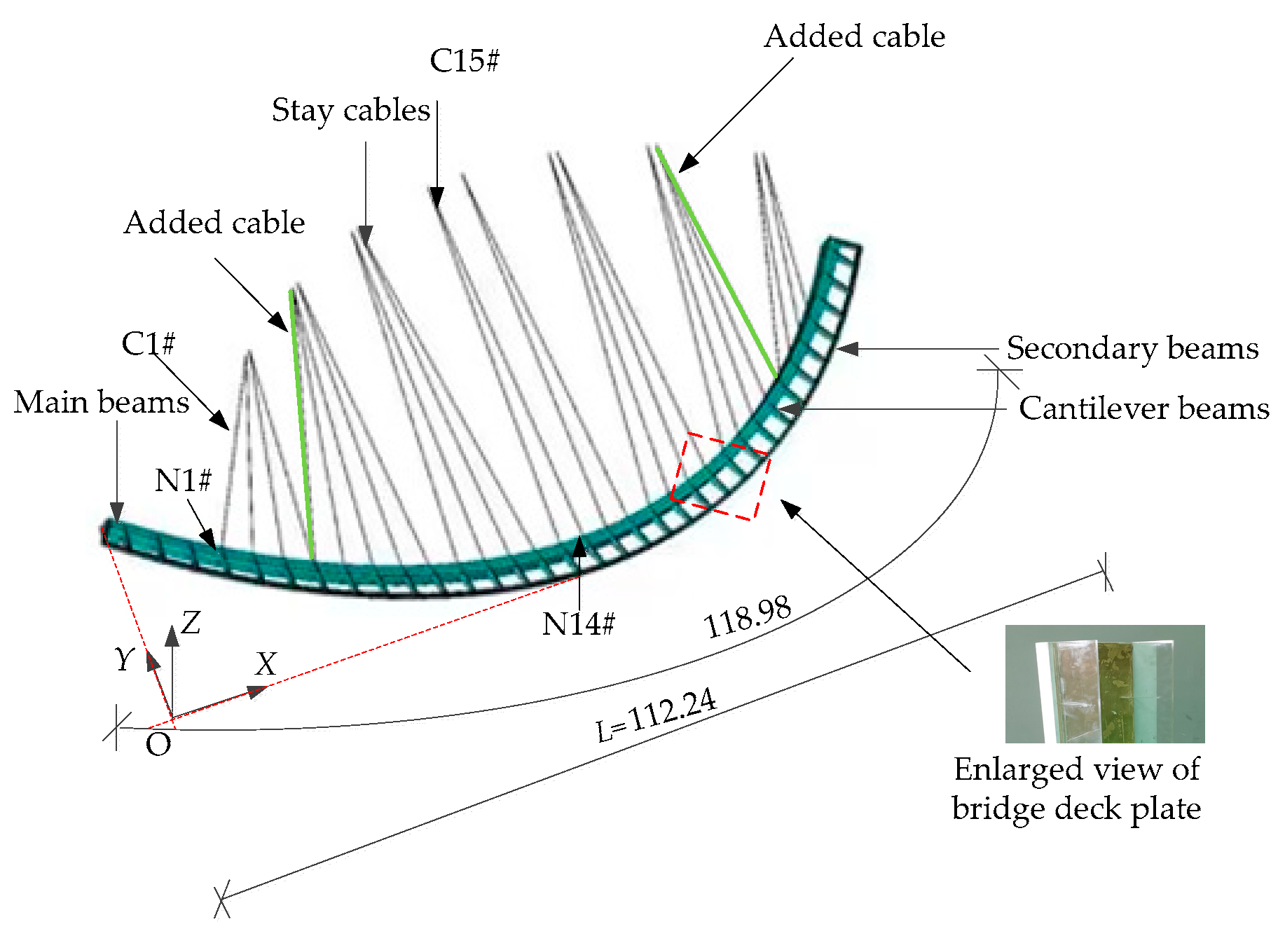
2.1. Aerostatic Force Tests of a CBUSB

The model takes a glass landscape bridge in Hanzhong City, China as an analysis case. The CBUSB consists of the main beam, secondary beam, cantilever beam, and stayed cable (as the structure of the added cable is not considered in Figure 1). In the design process, we consider the center line as a circular arc. The arc length and straight length L of the main beam are 118.98 and 112.24 m, respectively, and 28 cables are symmetrically arranged throughout the bridge. As shown in Figure 1, a coordinate system is established, where C is the cable; N is the connection point of the main beam and cable; 1#~15# is the number in the positive direction along the X-axis; and C5# is the newly added cable in Section 3.2. The X-axis and Y-axis are parallel and perpendicular to the tangent line of the middle node of the outer ring beam span, respectively. The origin of the coordinate is the crossover point between the left end of the bridge along the negative Y-axis and the tangent line of the middle node of the outer ring beam span. The direction of acceleration of gravity is negative along the Z-axis.
The wind tunnel test was performed in the TK-400 DC wind tunnel laboratory of the Tianjin research institute for water transport engineering in China. The dimensions of the wind tunnel laboratory were 15.0 (length) × 4.4 (width) × 2.5 m (height), and its form was a DC blow-out type. The fan power was 400 kW, and the test wind speed was continuously adjustable from 0 to 30 m/s. The aerostatic force tests need to meet the requirements of a similar shape to the rigid stage model and the rigidity of the model is large enough [20]. According to the size of the wind tunnel laboratory and the bridge in the case, the geometric scale ratio of the stage model was determined to be 1:100. The main parameters of the sectional model, the produced sectional model, and the wind field characteristics used in this test were detailed in Table 1, Figure 2 and Chapter 3.2 in the paper of Zhao et al. [1]. The aerodynamic coefficients were determined by aerostatic force tests, and the cases of test wind attack angle were set to −12°–12° and Δθ = 10, for a total of 25 cases.

2.2. Building of the Finite Element Model of the CBUSB

The geometric nonlinear characteristic of the cable-stayed bridge has a great influence on the calculation results of the structural performance analysis after the bridge cable breakage, which needs to be considered in the finite element model [21]. The influencing factors of the geometric nonlinear characteristic on the long-span cable-stayed bridge include the sag influence caused by the dead weight of the cable and the large deformation influence that is the change of the structural geometry caused by the large deformation.
The sagging influence of cable-stayed cable is generally considered by the equivalent elastic modulus method [22,23], and the equivalent elastic modulus of each cable is calculated by the Ernst formula as follows [24]:
E e q = E 1 1 + γ 2 L h 2 12 σ t 3 E
where Eeq and E are the equivalent elastic modulus and Young’s modulus of the cable, respectively; γ is the unit dead weight length of the stayed cable; Lh is the horizontal projected length of the stayed cable; and σt is the cable stress. The updated Lagrange formula method is used to calculate the geometric nonlinearity caused by the large deformation influence of the cable-stayed bridge [25,26], which is realized by checking the command “NLGEOM” in ANSYS.
The cable break process will have a large impact influence on the structure, which may lead to continuous break of the cable or brittle failure of the structure [9]. The whole cable break process occurs in a very short period of time and involves three states. States 1, 2, and 3 indicate before, during, and after the cable breakage, respectively. Time-varying loads are used to simulate the influence of impact loads caused by cable breakage [27,28] (as shown in Figure 2). In the Figure 2, t denotes the time when the CBUSB is subjected to wind loads; t0 is the time point when the cable starts to break; Δt is the cable break time, taken as 0.05 s [11]; t1 is the end time point of the cable breakage, and F0(t0) is the instantaneous value of the time-varying load F0(t) when t0 is taken.
(1)
State 1 corresponds to the time t < t0, when the structure was not broken. In the structural dynamic characteristics analysis after accidental cable breakage, t0 can be determined for research purposes [27,28]. Before cable breakage, the loading time step is 0.125 s, and t0 equals 130 s. The dynamic characteristics during the unbroken cable phase due to random wind loads were analyzed based on a sample size of 1040(=130/0.125). The cable breakage due to accidental factors was selected as occurring at the target cable. The cable force time-varying value F0(t) of the target cable was extracted by numerical analysis with t < t0. During the broken cable modeling analysis, the target cable was removed and F0(t) was used to simulate the dynamic action of the target cable on the bridge to achieve the equivalent bridge forces before cable breakage.
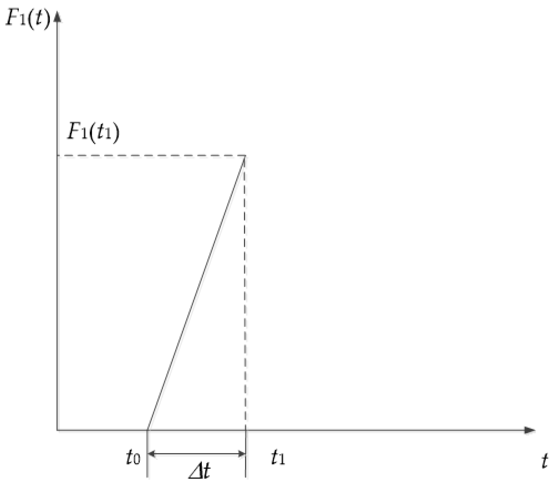
(2)
State 2 corresponds to the time t0tt1, when the structure was under the process of cable breakage. During cable breakage, the loading time step is 0.0001, and Δt equals 0.05 s. The structure was in the process of cable fatigue, and both F0(t0) and F1(t) were applied at the connection point of the target cable and the main beam. The direction of F0(t0) is opposite to that of F1(t); the former is the pulling force and the latter is the pushing force. The bridge was under the equivalent tensile force F0(t0) because the cable was not completely broken.
(3)
State 3 corresponds to the time t1 < t, when the structure was in the stage of post-breakage. The target cable is no longer applied by F0(t0) and F1(t) at the connection point of the target cable and the main beam., with a time step of 0.125 s. The dynamic characteristics after cable breakage by random wind loads were analyzed based on a sample size of 3000.

3. Parametric Analysis of Cable Fracture

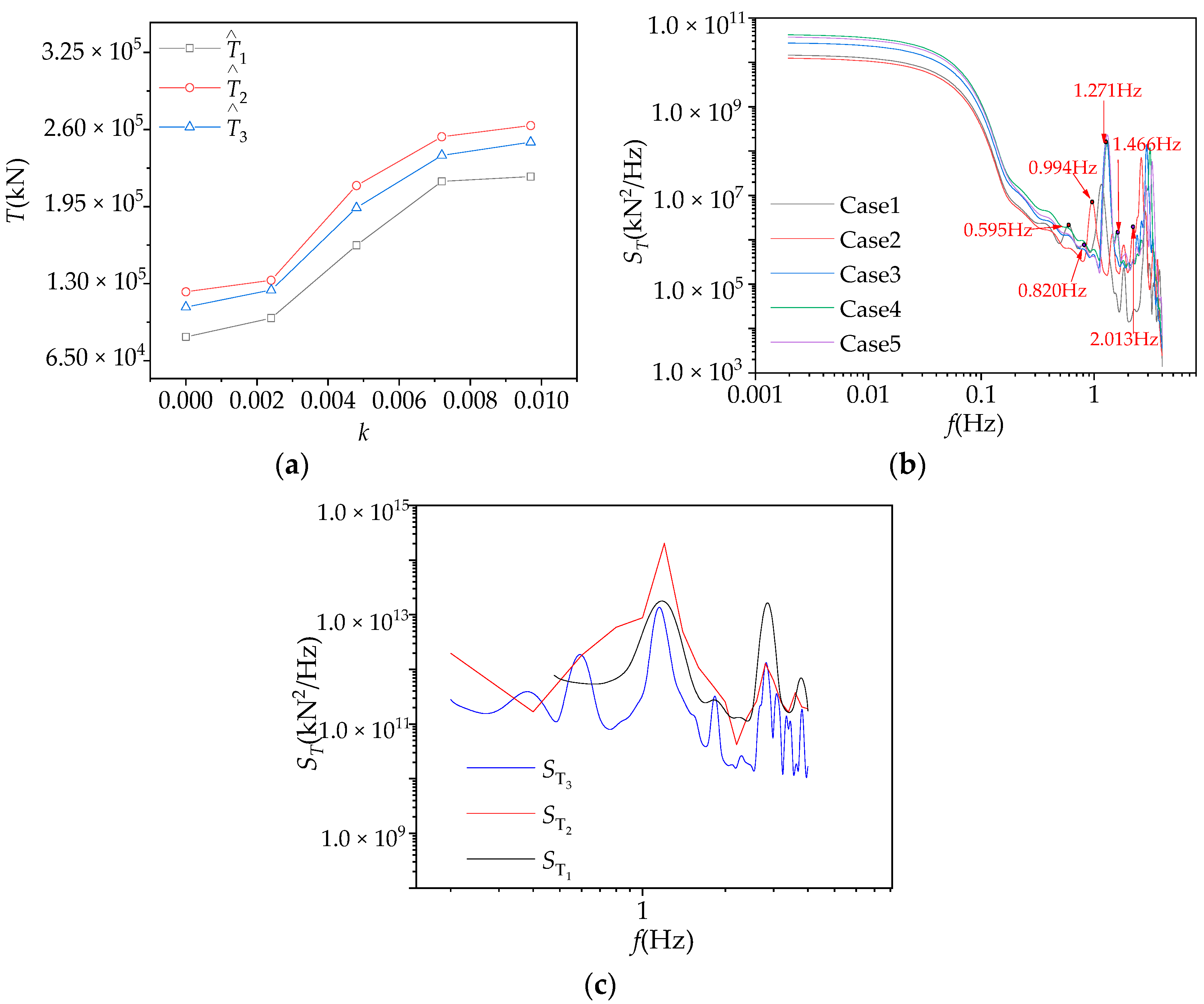
3.1. Analysis of Influence Parameters of Curvature Change

Curved beam cable-stayed bridges are more complexly affected by wind loads due to their characteristics. Previous studies [13,29] have shown that an unbalanced structural response is generated due to the change of curvature, the different rigidity of the inner and outer beams, and the incoming-flow wind loads acting on the curved beam bridge at a specific wind attack angle. As a result, an unbearable tensile force on the cable is produced, and a fortuity of cable break is caused. Therefore, this Section will study the influence of its changes on the dynamic response of the broken cable of the curved beam stayed bridge by wind loads from five different curvatures k of 0.0000, 0.0024, 0.0048, 0.0072, and 0.0097.
The curvature of the five finite element models adopted in this section is based on the 1 to 5 cases of the CBUSB literature studied by Zhao et al. [1]. The finite element models under the 5 cases are shown in Figure 3. In the process of the curvature change, the cross-sectional shape of the bridge and the positions of the fixed supports at both ends are not changed. The position of the hanging point of the cable and the main beam of the bridge also remains unchanged, and the projection of the cable in the X-Y plane is kept on the same line as the cantilever beam. The Z-axis coordinates of the fixed hinge support at the suspension point of the cable remain unchanged, as shown in Figure 1. C15# is selected as the breaking target cable, and the break simulation of the cable under 5 cases is carried out.
Figure 4a shows the T ^ of C14# under three states of cable breakage and five curvature cases, where T ^ is the biggest value of the cable force and subscript 1, 2, and 3 denote the moments t < t0, t0tt1, and t > t1, respectively. When curvature increases, the T ^ throughout the cable breakage increases (as shown in Figure 4a). As the curvature increases, the force on the remaining cable of state 3 increases, indicating that remaining cables are more likely to approach the allowable value of the maximum cable strength stress to cause cable fatigue failure. As shown in Figure 4a, T ^ is increased by the impact loads generated in state 2. With the impact loads tending to 0, the internal force of the bridge structure is redistributed, so T ^ 3 is higher than T ^ 1 . Figure 4b shows the cable force spectrum of C14# throughout the cable breakage in five curvature cases. In Figure 4b, f is the frequency and ST is the cable force power spectral density. The peak frequencies in ST include the bridge natural frequencies of 0.595 Hz, 0.994 Hz, 1.271 Hz, 1.304 Hz, and 1.310 Hz and many peak frequencies that are quite different from the natural frequency, such as 0.820 Hz, 1.466 Hz, and 2.013 Hz. The structural vibration modes of the bridge and cable corresponding to these peak frequencies contribute significantly to the CBUSB wind vibration, which shows that the design of cable-stayed bridges should consider the adverse influence of the strong nonlinear vibration of the cable on CBSUBs after the cable breakage.
The peak along-wind displacement U ^ throughout the cable breakage at the connection point under the 5 curvature cases when the target cable C15# (X = 56.726) breaks are shown in Figure 5a, where U is the along-wind displacement and X is the X-axis coordinate value (coordinate system as shown in Figure 1) of the bridge and cable connection point. As the curvature increases, the peak U ^ decreases, indicating that increasing the curvature can make the lateral stiffness of the bridge larger and reduce the U ^ caused by impact loads. However, the inhibition of U by increasing curvature is nonlinear, and the inhibition will level off when a certain value is reached. The U ^ of case 3 throughout the cable breakage is shown in Figure 5b. The impact loads generated by the cable breakage increases U ^ from wind-induced vibration. The closer the location of the broken cable, the greater the influence of impact loads generation on U ^ . The along-wind displacement spectrum of case 5 within 3 states is shown in Figure 4c. The first-order frequency of states 1, 2, and 3 is 0.60 Hz, 1.18 Hz, and 1.20 Hz, respectively, which indicates that the along-wind displacement spectrum of case 5 throughout the cable breakage can give a good inclusion of the along-wind displacement at different cable breakage states.
Combined with the analysis of Figure 5a,c, after using the band-pass filter method [30], it is obtained that the ratio of the resonance response to the fluctuating response in cases 1 and 5 is 44% and 28%, respectively. As the curvature increases, this ratio decreases, indicating that the curvature increases, the U ^ decreases (indirectly reflecting the decrease of the stress amplitude of the structure) and the ratio of the resonance response decreases (indicating the decrease in the number of dynamic cycles of the structure), which can reduce the possibility of fatigue damage.
The first-order frequency of the CBUSB increases with increasing curvature, demonstrating that the increase of curvature moves the excitation frequency of the resonance response far away from the wind dominant frequency (0.006–0.037 Hz); thus, the resonance energy excited by wind loads decreases. Considering the influence law of the CBUSB along-wind displacement response and cable tension response, when 0.0048 ≤ k ≤ 0.0052, the influence of broken cables on the wind-induced vibration response of bridges is the least significant, which can ensure the safety of CBUSBs.

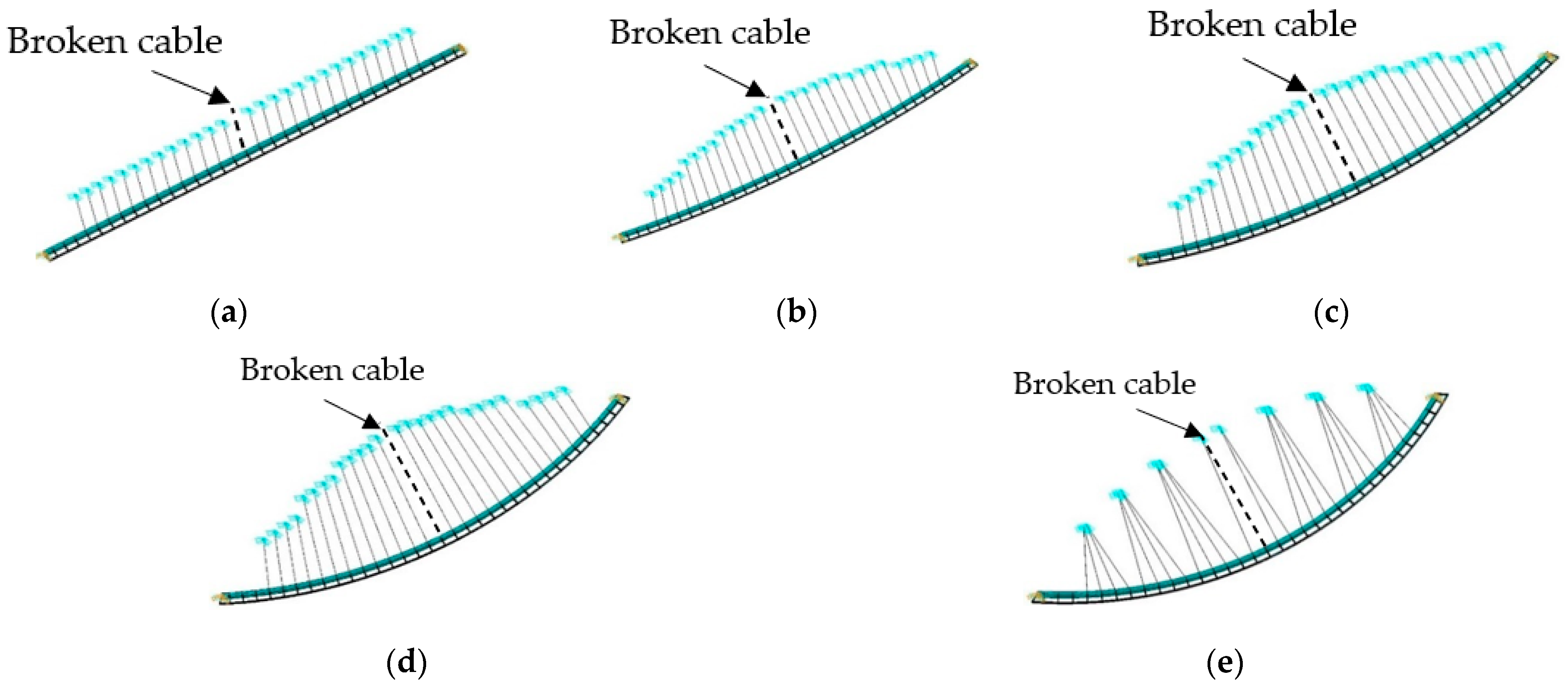
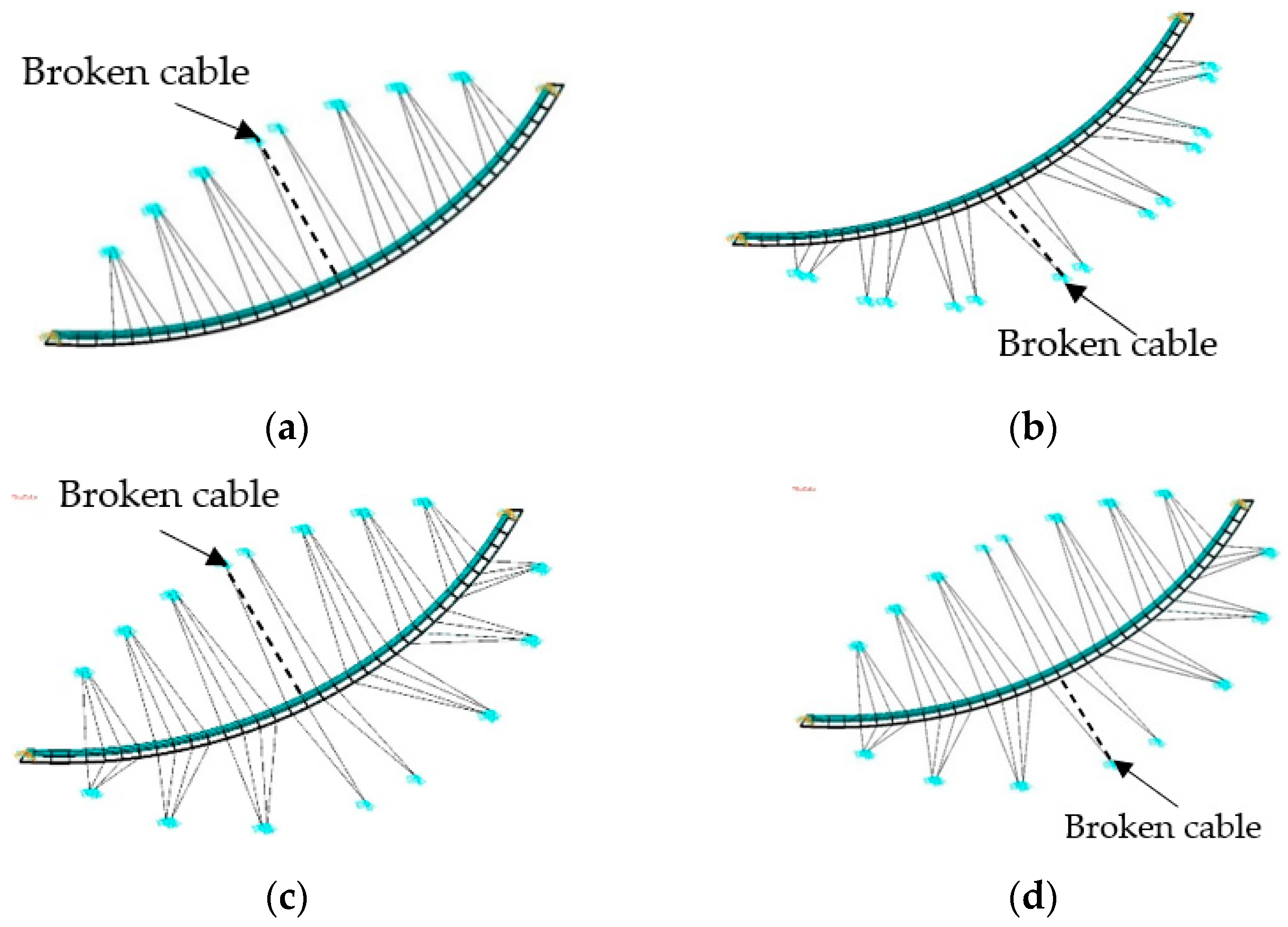
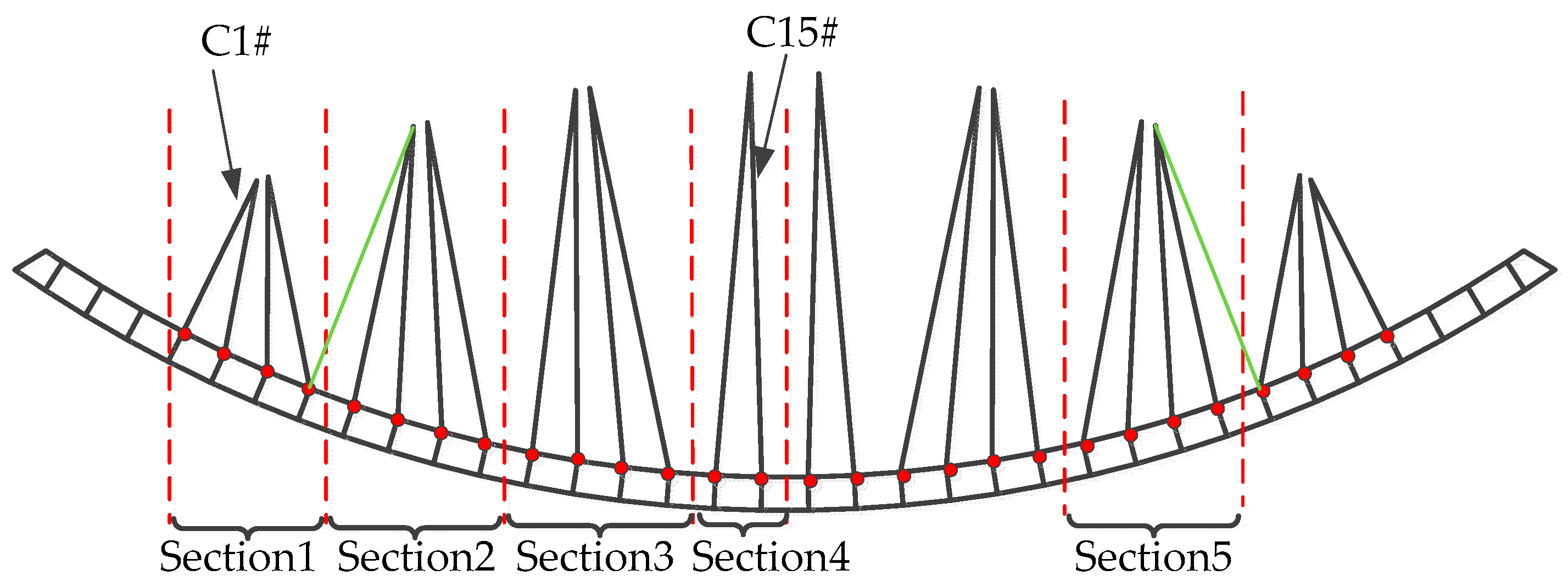
3.2. Analysis of the Cable Arrangement Case

As the cable arrangement cases changes, the mechanical and dynamic characteristics of the CBUSB also change, thereby affecting the structural dynamic response after cable breakage. This Section will study the influence of different cable arrangement cases on the dynamic response of the CBUSB through the following four cable arrangement cases. Figure 6a,b show the arrangement of cables on the side close to or far from the center of curvature; Figure 6c,d show that the position of cable breakage is close to and far from the middle side of the curvature, respectively, under the arrangement of cables on both sides. C15#, as the breaking target cable, is used to simulate the breaking process of the cable by the dynamic response method, and numerical analysis is carried out for each case.
Figure 7a shows the T ^ of the analysis cable C14# throughout the cable breakage under different cable arrangement cases. The impact loads applied to the unilateral arrangement of the cable throughout the breakage are larger than that of the bilateral arrangement of the cable (as shown in Figure 7a). Compared with the 4 cases, the influence of the bilateral arrangement of cables on the remaining cable force in state 3 is minimal. The maximum T ^ of case 4 is 1.6 × 10⁵ kN, and the cable force is only increased by 6.4%. When cables are arranged unilaterally on the side away from the curvature center, it leads to a more pronounced redistribution of the wind-induced vibration internal force. The ST throughout the cable breakage under four cases is shown in Figure 7b. The resonance responses of cases 2 and 4 account for 54% and 32% of the fluctuating response, respectively. The analysis shows that when the cable arrangement is unilateral, the structure is more affected by the impact load caused by the cable breakage, and resonance damage easily occurs after the cable breakage.
When the target cable C15# breaks, the U ^ and its power spectrum SU under 4 cable arrangement cases are shown in Figure 7c,d, respectively. As shown in Figure 7c,d, the mid-span point U ^ under case 1 and case 2 is 22.55 mm and 27.76 mm, respectively, which indicates that the static wind action of case 1 is less than that of case 2. The first-order frequency of case 1 and case 2 is 1.36 Hz and 1.31 Hz, respectively, which indicates that case 1 is far from the wind dominant frequency (0.006–0.037 Hz) and has less resonance response than case 2. Additionally, the double-sided arrangement of the cable reduces the energy generated by the structural resonance and the influence on the dynamic response of the CBUSB in state 2. The first-order frequencies of case 3 and case 4 are 1.69 Hz and 1.52 Hz, respectively, which shows that it is less prone for case 3 to resonate due to excitation by the wind. Through peak value statistical analysis, the case 3 and case 4 ration of mean displacement response to the total response accounts for 98.37% and 98.49%, respectively, which indicates that the CBUSBS is quasi-static after cable breakage when the cables are arranged on both sides. From the perspective of reducing the damage of CBUSBs caused by cable breakage and wind, cables should be arranged on both sides of the curved beam and the cables close to the curvature center should be designed more strictly. If the unilateral arrangement case is adopted, the cables should be arranged at the side close to the center of curvature.

4. Analysis of Broken Cables in Risk Regions of Bridges

4.1. Wind-Induced Vibration Response Assessment of Bridges with Cable Breakage in Different Regions

As the key member of the cable-stayed bridge, the cable is easily damaged or even broken during the construction and operation of the bridge. To find out the risk region regarding structural safety after the CBUSB cable breakage, four regions are divided according to the symmetry of the CBUSB (as shown in Figure 8). The cable breakage research is carried out in each region in turn and a total of fourteen cases are shown in Table 1. The dynamic response method is used to simulate the cable break process, and numerical analysis is carried out for each case.
The relationship between the wind-induced vibration response of the numerical analysis and the change in the cable breakage cases is shown in Figure 9. Figure 9a shows that the impact loads of the CBUSB in regions 1 and 2 are relatively large. It can be observed in Figure 9b that, with the change of the position of cable breakage from the side span to the middle span, the highest U ^ by wind loads is reached at region 2, which indicates that the total response of the wind-induced vibration is the largest at region 2. The U ^ under the four cases fluctuates around 10.02 mm in state 2. According to U, T, and the symmetry, a cable breakage in the two regions from 7/33L to 7/22L and 26/33L to 15/22L will have the most adverse influence on the bridge wind-induced vibration response. Therefore, those regions are called risk regions.
The cable tension spectrums of cable breakage under four cable cases in risk regions are shown in Figure 10a. With the change of the location of cable breakage from near the bridge end to far away from the bridge end, the resonance energy excited by wind loads increases, and the proportion of the high-order modal resonance response gradually becomes higher than that of the low-order modal resonance response. Therefore, to reduce the possibility of resonance, we should properly consider high-frequency vibration reduction. The along-wind displacement spectrums of cable breakage cases in the risk regions are shown in Figure 10b. The peak response distribution of case 5 in the frequency from 2.5 Hz to 4.0 Hz is very dense, which indicates that the modal coupling phenomenon is prone to occur. The resonance response accounts for 73% of the fluctuating response. Thus, we can see that the C5# breakage in risk regions is very likely to cause structural damage, which will increase the possibility of other cable breakages again in risk regions.

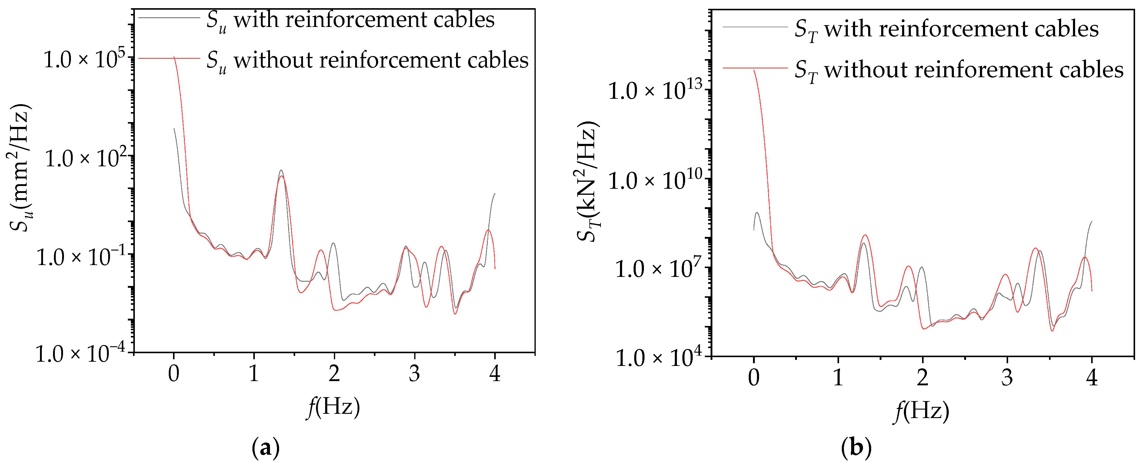
4.2. Cable Reinforcement Scheme

The risk regions were identified through Section 4.1 as 7/33L~7/22L (as region 2 in Figure 8) and 26/33L~15/22L (as region 5 in Figure 8). The broken cables in these regions are likely to cause coupling vibration between the cable and the bridge. To improve the safety of the CBUSB after the cable breakage, this Section will add a stayed cable in each risk region. The reinforcement cable structure is the same as the adjacent stayed cable, and the overall bridge will still be symmetrically arranged, as shown in Figure 1.
The results of calculating whether the reinforcement cables influence the T ¯ and T r m s of the cable structure tension response are shown in Table 2 and Table 3. By analyzing the data in Table 2 and Table 3, it can be seen that the reinforcement cables reduced tension response by at least 12% throughout the cable breakage. Meanwhile, the mass of the cable with the reinforcement cable increased from 3821 kg to 4068 kg, within an increase ratio of 6.4%. Therefore, the scheme of adding reinforcement cables at the most unfavorable cable break position can increase the safety of the broken cable at a relatively small cost, which means that the scheme is effective.
Table 4 and Table 5 show the comparison of the U ¯ and U r m s of the bridge with or without reinforcement cables throughout the cable breakage. It can be seen that, when the target cable breaks, reinforcement cables have a certain inhibitory influence on the along-wind displacement response in the three states of the cable breakage. States 1, 2, and 3 are reduced by 42%, 24%, and 14% respectively, reducing the influence of cable breakage on structural safety.
When C5# is the target cable, the calculations of the tension of the analyzed cable and its displacement at the end corresponding to the position of the beam with or without reinforcement cables are shown in Figure 11. When cables are added, the first-order frequency of the structure itself does not change much, but the second-order frequency increases from 1.81 Hz to 1.99 Hz, within an increase ratio of 9.9%. After cables are added, the modal coupling phenomenon is less likely to occur after the cable breakage in the risk regions, which improves CBUSB safety.

4.3. DAF Value of Cable Structure Breakage

DAF is an important parameter in the cable-stayed bridge’s design when considering the adverse influence of cable breakages. The American code (DC45.1-2012) [5] promulgated by the United States PTI stipulates that, when any cable of the cable-stayed bridge breaks, the remaining structure should be able to withstand the adverse influences caused by the broken cable. It is recommended that the DAF of the cable-stayed bridge be taken as 2.0 in the case of cable breakage. In Eurocodes 3 (EN1991-2) [31], the DAF value under accidental loads is defined as 1.5. The French code (DT2832-2001) [32] recommends that the value range of DAF is 1.5~2.0 for the cable-stayed bridge’s design.
In order to ensure that a CBUSB is in a safe state and can continue to operate after cable breakage, the DAF value when a single cable is broken can be determined through Equation (2) in this section.
D A F = R d y n R 0 R s t a t i c R 0
where R0 is the mean dynamic response of the cable-stayed bridge excited by wind loads when t < t0; Rdyn is the peak dynamic response of the bridge when t0tt1; and Rstatic is the mean dynamic response after the impact loads disappear when t1 < t.
Based on the dynamic calculation timescale values in Section 3.2, the DAF of the along-wind displacement and the cable tension are determined. The results calculated by Equation (2) are shown in Table 6. The cable tension DAF and along-wind displacement DAF of the most unfavorable cable are 1.2 and 1.4, respectively. With the addition of reinforcement cables, the DAF of CBUSB decreases, which indicates that reinforcement cables can reduce the influence of the most unfavorable cable breakage on the wind-induced vibration response and facilitates the operation and maintenance of the bridge under wind loads. There are differences between the recommended DAF values of broken cable design in the US, France, and European Union codes and those of the CBUSB determined by dynamic calculation analysis, among which the difference from European Union code is the smallest. Therefore, the DAF in EU code is more suitable for the CBUSB structure.

5. Conclusions

Based on the wind tunnel test results, the established impact load model, and the finite element analysis method, this paper analyzes the influence of the cable breakage on the CBUSBs’ wind-induced vibration characteristics under the condition of structural parameters (curvature and cable arrangement) and the location of the cable breakage. Afterwards, the DAF recommendation values which can consider the influence of the cable breakage on CBUSBs’ peak wind-induced vibration are provided. The main conclusions are as follows:
  • In wind-induced vibration analysis considering the influence of cable breakages, it is necessary to determine the aerodynamic coefficients of the CBUSB by wind tunnel tests of its sectional model. To analyze the influence of cable breakage on the whole wind-induced vibration process of CBUSBs, the whole time-domain calculation should be divided into three states: before cable breakage, during cable breakage, and after cable breakage.
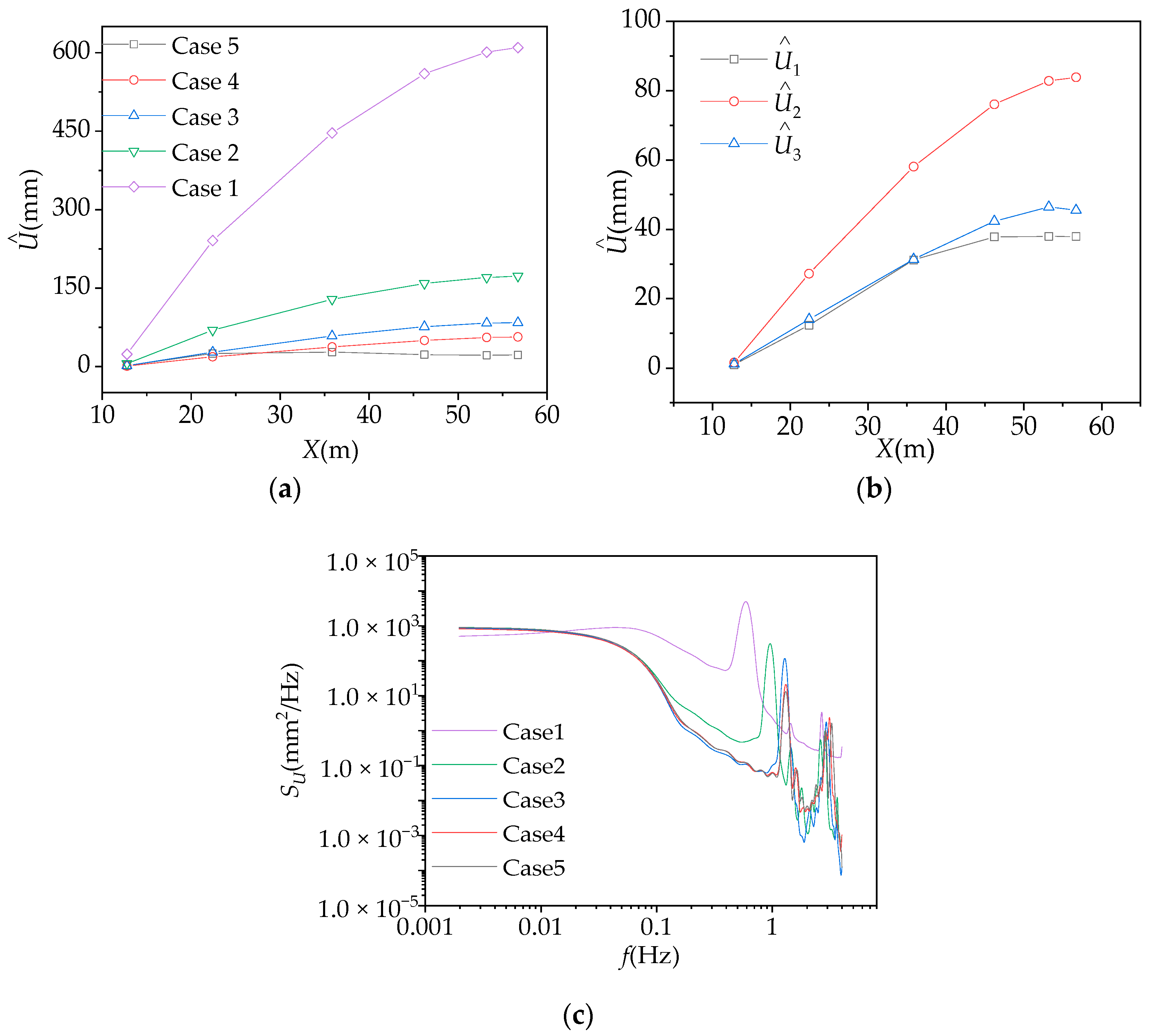
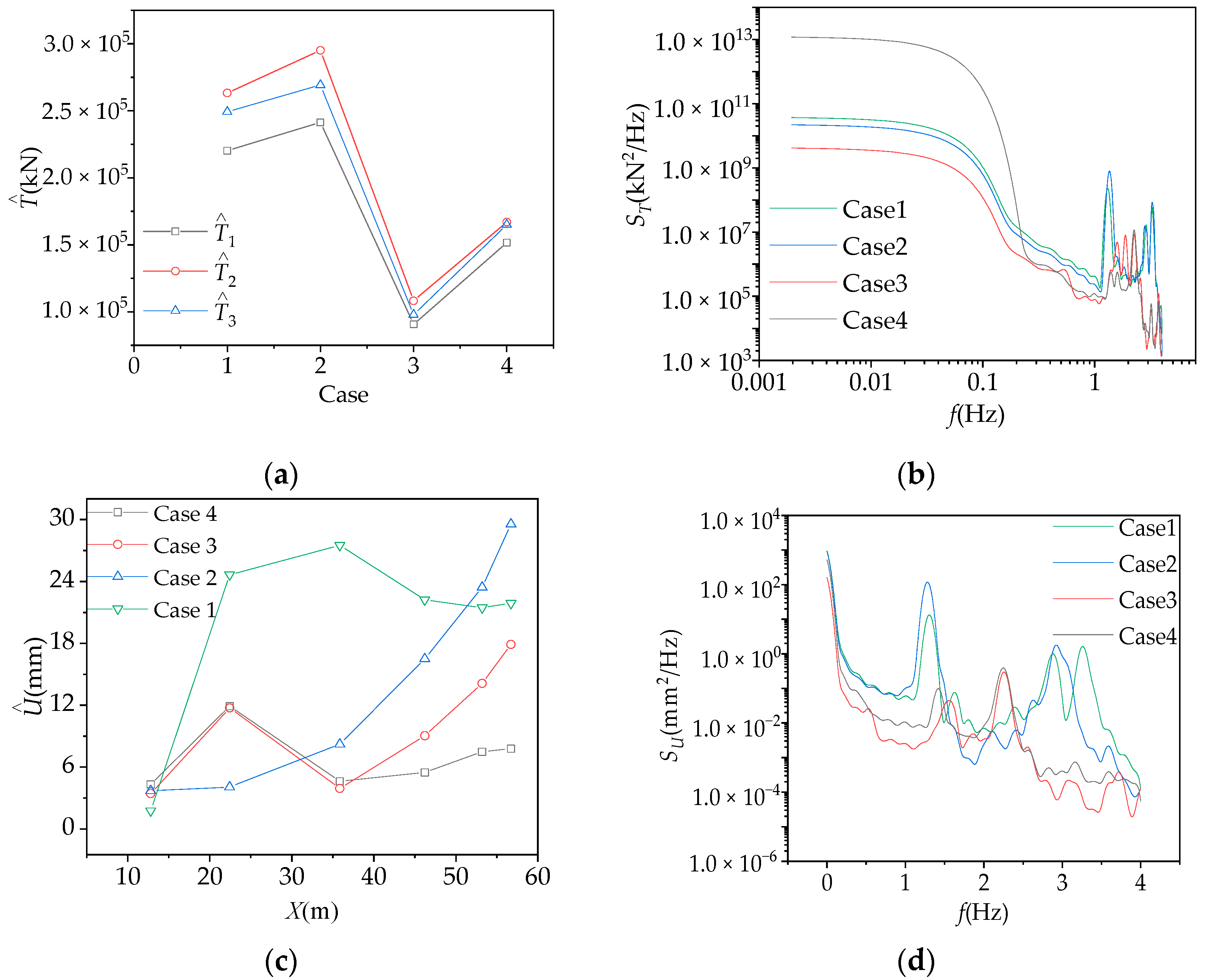
  • With increasing curvature, the main vibration mode of the CBUSB is far away from the wind predominant frequency, and the fluctuation component is changed, which makes the proportion of resonant response smaller. For CBUSBs with unilateral or bilateral cable arrangements, their wind-induced vibration behavior is significantly different. The former has dynamic characteristics and the latter has quasi-static characteristics. The peak wind-induced response of the CBUSB and the internal force redistribution effects due to the cable breakage are smaller when the cables are arranged on the side close to the curvature center than those when cables are arranged on the other side. Meanwhile, the former can be used as the optimal scheme for such structural design.
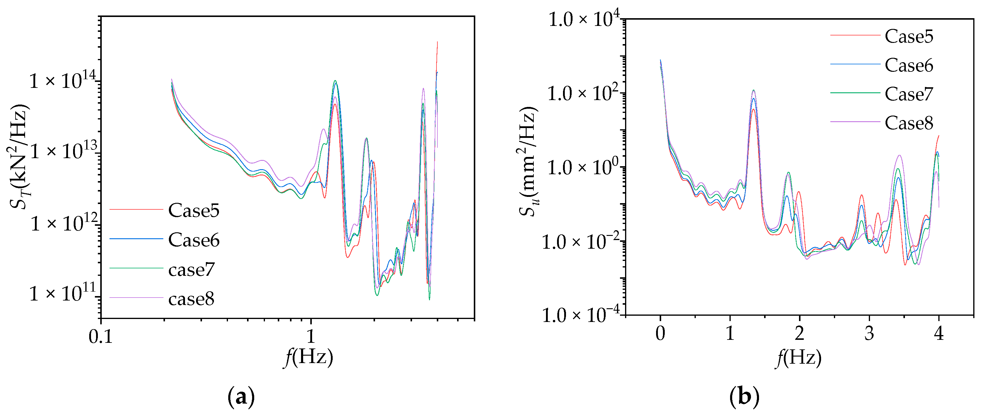
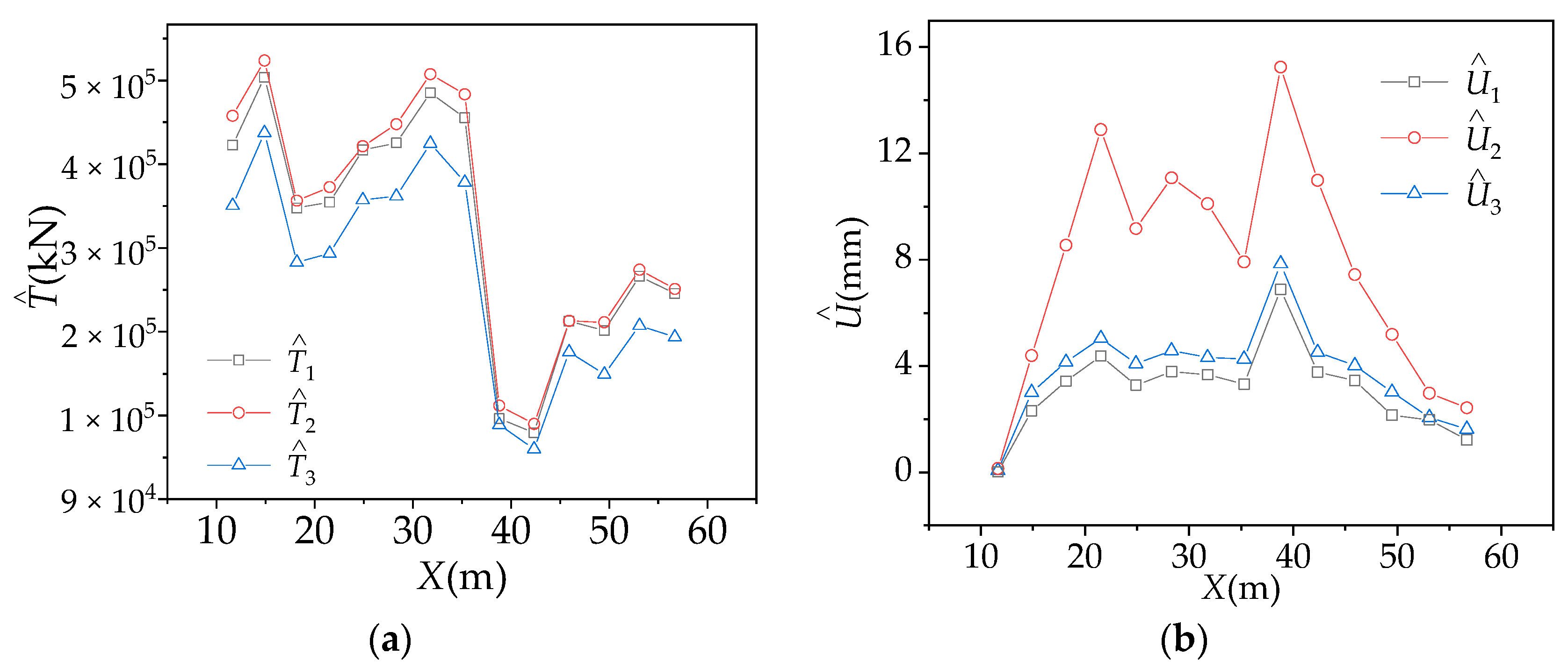
  • The breakage of the shortest cable at 7/33 to 7/22 of the curved beam length and its symmetry part can significantly increase the peak wind-induced response of CBUSBs, which leads the tension spectrum to have a dense distribution of higher-order frequencies. As the proportion of resonance response in fluctuating response increases, there is a possibility of cable breakage again. The DAF recommended values by existing codes do not consider the combined influence of wind and cable breakages, whereas the values provided in this paper accurately consider the amplification effect of wind-induced vibration caused by cable breakage.

Author Contributions

Conceptualization, S.Z.; Writing—review and editing, S.Z., Y.S. and Z.Y.; Formal analysis, S.Z. and Y.S.; Software, S.Z. and Y.S.; Supervision, S.Z. and Y.S.; Writing—original draft, Y.S.; Data curation, J.C.; Methodology, Z.Y.; Validation, Z.Y. and B.Z.; Resources, B.Z. and Z.W.; Project administration, X.Z.; Funding acquisition, Z.W. All authors have read and agreed to the published version of the manuscript.

Funding

This research was funded by the National Natural Science Foundation of China (52178458), Chongqing Natural Science Foundation (CSTB2022NSCQ-MSX0363), the China Postdoctoral Science Foundation (2022M720592), the Science and Technology Research Program of Chongqing Municipal Education Commission (Grant No. KJQN202001548), the Open Fund of Chongqing Key Laboratory of Energy Engineering Mechanics & Disaster Prevention and Mitigation (EEMDPM2021104), the Chongqing postdoctoral special Foundation (2021XM3057), the Chongqing Construction Science and Technology Plan Project (2022 8-8), the Open Research Project of University Enterprise Collaborative Innovation Center of Chongqing University of Science & Technology (Grant No. YKJCX2120620) and the special Funding for Postdoctoral Research Projects in Chongqing (2022CQBSHTB2051).

Data Availability Statement

Due to data privacy, no dedicated data links will be provided.

Conflicts of Interest

The authors declare no conflict of interest.

References

  1. Zhao, S.; Chen, J.H.; Yue, J.H.; Yan, Z.T.; Liu, J.; Zhang, B.; Chen, J.F. Sectional model wind tunnel test and research on the wind-induced vibration response of a curved beam unilateral stayed bridge. Buildings 2022, 12, 1643. [Google Scholar] [CrossRef]
  2. Briseghella, B.; Fa, G.; Aloisio, A.; Pasca, D.; He, L.; Fenu, L.; Gentile, C. Dynamic characteristics of a curved steel–concrete composite cable-stayed bridge and effects of different design choices. Structures 2021, 34, 4669–4681. [Google Scholar] [CrossRef]
  3. Zhao, G.; Wang, Z.; Zhu, S.; Hao, J.; Wang, J. Experimental study of mitigation of wind-induced vibration in asymmetric cable-stayed bridge using sharp wind fairings. Appl. Sci. 2022, 12, 242. [Google Scholar] [CrossRef]
  4. Wu, Y.; Wu, X.; Li, J.; Xin, H.; Sun, Q.; Wang, J. Investigation of vortex-induced vibration of a cable-stayed bridge without backstays based on wind tunnel tests. Eng. Struct. 2022, 250, 113436. [Google Scholar] [CrossRef]
  5. Cai, J.G.; Wang, F.L.; Feng, J. Conceptual design of large span spatial structure against continuous collapse. J. Archit. Eng. 2010, S1, 283–287. [Google Scholar]
  6. Yu, G.; Sun, L.M. Analysis of structural vulnerability of cable-stayed Bridges caused by broken cables. J. Tongji Univ. 2010, 38, 323–328. [Google Scholar]
  7. Guo, J.; Guan, Z. Optimization of the cable forces of completed cable-stayed bridges with differential evolution method. J. Struct. 2023, 47, 1416–1427. [Google Scholar] [CrossRef]
  8. Abdel, F.M.T.; Abdel, F.T.T. Influence of pylon configuration on the response of cable-stayed bridges to sudden cable loss. Proc. Inst. Civ. En-Bridge. Eng. 2023, 176, 58–66. [Google Scholar]
  9. Xiang, Y.; Chen, Z.; Yang, Y.; Lin, H.; Zhu, S. Dynamic response analysis for submerged floating tunnel with anchor-cables subjected to sudden cable breakage. Mar. Struct. 2018, 59, 179–191. [Google Scholar] [CrossRef]
  10. DC45.1-2012; Recommendations for Stay Cable Design, Testing and Installation. P.T.I Farmington Hills: Farmington Hills, MI, USA, 2012; pp. 34–35.
  11. Mozos, C.M.; Aparicio, A.C. Numerical and experimental study on the interaction cable structure during the failure of a stay in a cable stayed bridge. J. Eng. Struct. 2011, 33, 2330–2341. [Google Scholar] [CrossRef]
  12. Cai, J.G.; Xu, Y.X.; Zhuang, L.P. Comparison of various procedures for progressive collapse analysis of cable-stayed bridges. J. Zhejing Univ. 2012, 13, 323–334. [Google Scholar] [CrossRef]
  13. Li, S.H.; Ren, J.Y. Analytical study on dynamic responses of a curved beam subjected to three-directional moving loads. Appl. Math. Model. 2018, 58, 365–387. [Google Scholar] [CrossRef]
  14. Qian, C.; Zhu, L.; Zhu, Q.; Ding, Q.; Yan, L. Pattern and mechanism of wind-induced static instability of super-long-span cable-stayed bridge under large deformation. J. Wind. And. Ind. Aero. 2022, 221, 104910. [Google Scholar] [CrossRef]
  15. Atmaca, B.; Ghafoori, R.; Dede, T.; Ateş, Ş. The effect of post-tensioning force and different cable arrangements on the behavior of cable-stayed bridge. Structures 2022, 44, 1824–1843. [Google Scholar] [CrossRef]
  16. Xie, T.; Mohamed, A.M.S.; Elchalakani, M.; David, M. Experimental and analytical study of ultrahigh-performance fiber-reinforced concrete curved beams. J. Struct. Eng. 2020, 146, 91–92. [Google Scholar] [CrossRef]
  17. Wang, T.; Zhang, X.B.; Wang, L. The Investigation on dynamic response of cable-stayed bridge and train on bridge under cable break conditions. J. Southwest Jiaotong Univ. 2022, 258, 51–1277. [Google Scholar]
  18. Yang, X. Research on calculation method and Influencing factors of asymmetric cable-stayed Bridge. J. Lanzhou Jiaotong Univ. 2021, 1, 153–241. [Google Scholar]
  19. Yukari, A.; Hamid, V.; Bijan, S. A study on potential progressive collapse responses of cable-stayed bridges. J. Adv. Struct. Eng. 2013, 16, 689–706. [Google Scholar]
  20. JGJ/T 338-2014; Ministry of Housing and Urban-Rural Development of the People’s Republic of China. Standard for Wind Tunnel Test of Buildings and Structures; China Architecture and Building Press: Beijing, China, 2014.
  21. Shao, G.T.; Jin, H.; Jiang, R.N.; Xu, Y. Dynamic response and robustness evaluation of cable-supported arch bridges subjected to cable breaking. J. Shock. Vib. 2021, 2021, 6689630. [Google Scholar] [CrossRef]
  22. Zhang, Y.; Fang, Z.; Jiang, R.; Xiang, Y.; Long, H.; Lu, J. Static performance of a long-span concrete cable-stayed bridge subjected to multiple-cable loss during construction. J. Bridge. Eng. 2020, 25, 04020002. [Google Scholar] [CrossRef]
  23. Ali, K.; Katsuchi, H.; Yamada, H. Comparative study on structural redundancy of cable-stayed and extradosed bridges through safety assessment of their stay cables. J. Eng. 2021, 7, 111–123. [Google Scholar] [CrossRef]
  24. Gimsing, N.J.; Georgakis, C.T. Cable Supported Bridges: Concept and Design; John and Wiley and Sons: Hoboken, NJ, USA, 2011; pp. 1–145. [Google Scholar]
  25. Zhou, Y.; Chen, S. Reliability assessment framework of the long-span cable-stayed bridge and traffic system subjected to cable breakage events. J. Bridge. Eng. 2017, 22, 04016133. [Google Scholar] [CrossRef]
  26. Wen, Y.; Zhou, Z. Qualification of the ernst formula for modeling the sag effect of super-long stay cables in the long-span railway cable-stayed bridges. Structures. 2022, 45, 99–109. [Google Scholar] [CrossRef]
  27. Zheng, X.B.; Zhang, G.; Song, Y.F. Dynamic response of cable failure of steel truss cable-stayed bridge. J. Changan Univ. 2017, 37, 70–77. [Google Scholar]
  28. Yang, J. Structural Redundancy and System Reliability of Highway Bridges; University of Maryland: College Park, MD, USA, 2015. [Google Scholar]
  29. Yang, Y.B.; Wu, C.M.; Yau, J.D. Dynamic response of a horizontally curved beam subjected to vertical and horizontal moving loads. J. Sound. Vib. 2001, 242, 519–537. [Google Scholar] [CrossRef]
  30. Lawrence, J.C.; Terry, J.F. The Band Pass Filter. Int. Econ. Rev. 2003, 44, 435–465. [Google Scholar]
  31. EN1991-2; Eurocode 1: Action on Structures—Part 2: Traffic Loads on Bridges. British Standard Institution: London, UK, 2006; pp. 134–137.
  32. DT2832-2001; Haubans. Recommandations de la Commission Interministérielle de la Précontrainte. Service d’Etudes Techniques des Routes et Autoroutes: Bagneu, France, 2001; pp. 179–181.
Figure 1. Diagram of the curved beam unilateral stayed bridge (Unit: m).
Buildings 13 01038 g001
Figure 2. The time history value of the impact load of cable breakage.
Buildings 13 01038 g002
Figure 3. Diagram of curvature cases: (a) Curvature case 1(k = 0.0000); (b) Curvature case 2 (k = 0.0024); (c) Curvature case 3 (k = 0.0048); (d) Curvature case 4 (k = 0.0072); and (e) Curvature case 5 (k = 0.0097).
Buildings 13 01038 g003
Figure 4. Cable tension response analysis with a curvature transform: (a) peak tension; (b) tension spectrum; and (c) cable tension spectrum analysis of case 5 throughout the cable breakage.
Buildings 13 01038 g004
Figure 5. Wind-induced along-wind displacement analysis of the CBUSB with curvature transform: (a) peak displacement; (b) peak displacement of Case 3; and (c) bridge displacement response spectrum.
Buildings 13 01038 g005
Figure 6. Diagram of stayed cable cases: (a) stayed cables case 1; (b) stayed cables case 2; (c) stayed cable cases 3; and (d) stayed cable cases 4.
Buildings 13 01038 g006
Figure 7. Analysis of wind-induced response with a stayed cable layout: (a) peak tension analysis; (b) tension spectrum analysis; (c) peak displacement analysis; and (d) displacement spectrum analysis.
Buildings 13 01038 g007
Figure 8. Diagram of the CBUSB cable region division.
Buildings 13 01038 g008
Figure 9. Wind-induced vibration response analysis of cable arrangement throughout cable breakage: (a) cable tension and (b) bridge displacement.
Buildings 13 01038 g009
Figure 10. Response spectrum analysis of fractured cables in risk regions: (a) cable tension response spectrum and (b) bridge displacement response spectrum.
Buildings 13 01038 g010
Figure 11. Analysis on the response spectrum of the analyzed cable with or without reinforcement cables: (a) bridge displacement response spectrum and (b) cable tension response spectrum.
Buildings 13 01038 g011
Table 1. Cable breakage cases.
Cable Case NumberCable Region DivisionCable Number
Case 1Section 1C1#
Case 2C2#
Case 3C3#
Case 4C4#
Case 5Section 2C6#
Case 6C7#
Case 7C8#
Case 8C9#
Case 9Section 3C10#
Case 10C11#
Case 11C12#
Case 12C13#
Case 13Section 4C14#
Case 14C15#
Table 2. Comparison of mean cable tension response with or without reinforcement cables.
States of Cable Breakage T ¯ with Reinforcement Cables (kN) T ¯ without Reinforcement Cables (kN) Change Ratio (%)
State 12.25 × 1052.67 × 105−16
State 22.69 × 1053.07 × 105−13
State 33.08 × 1053.50 × 105−12
Table 3. Comparison of root-mean-square value results of cable tension response with or without reinforcement cables.
States of Cable Breakage T R M S with Reinforcement Cables (kN) T R M S without Reinforcement Cables (kN) Change Ratio (%)
State 12.25 × 1052.56 × 105−12
State 22.69 × 1053.08 × 105−13
State 33.08 × 1053.50 × 105−12
Table 4. Comparison of the mean along-wind displacement response of the bridge with or without reinforcement cables.
States of Cable Breakage U ¯ with Reinforcement Cables (kN) U ¯ without Reinforcement Cables (kN) Change Ratio (%)
State 1712−42
State 21520−24
State 32428−14
Table 5. Comparison of root-mean-square value results of the along-wind displacement responses of the bridge with or without reinforcement cables.
States of Cable Breakage U R M S with Reinforcement Cables (kN) U R M S without Reinforcement Cables (kN) Change Ratio (%)
State 1713−46
State 21520−24
State 32428−14
Table 6. DAF considering the influence of the cable breakage.
Determination Method of DAF ValueTension DAFAlong-Wind Displacement DAF
Numerical simulation for CBUSBs without adding cables1.41.6
Numerical simulation for CBUSBs with adding cables1.21.5
Calculated through U.S. code (DC45.1-2012)2.0
Calculated through EU code (EN1991-2)1.5
Calculated through French code (DT2832-2001)1.5~2.0
Disclaimer/Publisher’s Note: The statements, opinions and data contained in all publications are solely those of the individual author(s) and contributor(s) and not of MDPI and/or the editor(s). MDPI and/or the editor(s) disclaim responsibility for any injury to people or property resulting from any ideas, methods, instructions or products referred to in the content.

