Review

The Phenomenon of Cracking in Cement Concretes and Reinforced Concrete Structures: The Mechanism of Cracks Formation, Causes of Their Initiation, Types and Places of Occurrence, and Methods of Detection—A Review

by
Grzegorz Ludwik Golewski
Department of Structural Engineering, Faculty of Civil Engineering and Architecture, Lublin University of Technology, Nadbystrzycka 40 Str., 20-618 Lublin, Poland
Buildings 2023, 13(3), 765; https://doi.org/10.3390/buildings13030765
Submission received: 19 January 2023 / Revised: 24 February 2023 / Accepted: 12 March 2023 / Published: 14 March 2023
(This article belongs to the Special Issue Experiment and Analysis of Building Structures)

Abstract

:
Cracks and cavities belong to two basic forms of damage to the concrete structure, which may reduce the load-bearing capacity and tightness of the structure and lead to failures and catastrophes in construction structures. Excessive and uncontrolled cracking of the structural element may cause both corrosion and weakening of the adhesion of the reinforcement present in it. Moreover, cracking in the structure negatively affects its aesthetics and in extreme cases may cause discomfort to people staying in such a building. Therefore, the following article provides an in-depth review of issues related to the formation and development of damage and cracking in the structure of concrete composites. It focuses on the causes of crack initiation and characterizes their basic types. An overview of the most commonly used methods for detecting and analyzing the shape of microcracks and diagnosing the trajectory of their propagation is also presented. The types of cracks occurring in concrete composites can be divided according to eight specific criteria. In reinforced concrete elements, macrocracks depend on the type of prevailing loads, whereas microcracks are correlated with their specific case. The analyses conducted show that microcracks are usually rectilinear in shape in tensioned elements; in shear elements there are wing microcracks with straight wings; and torsional stresses cause changes in wing microcrack morphology in that the tips of the wings are twisted. It should be noted that the subject matter of microcracks and cracks in concrete and structures made of this material is important in many respects as it concerns, in a holistic approach, the durability of buildings, the safety of people staying in the buildings, and costs related to possible repairs to damaged structural elements. Therefore, this problem should be further investigated in the field of evaluation of the cracking and fracture processes, both in concrete composites and reinforced concrete structures.

1. Introduction

One of the main tasks of modern material engineering in the field of construction is the design and implementation of buildings in such a way as to achieve the greatest possible safety of the structure with the least possible financial outlay [1,2]. The properties of concrete materials, including their durability, are mainly determined by structural factors and the interrelations between the micro- and macrostructure of the material [3,4,5,6]. Cracks and cavities belong to two basic forms of damage to the concrete structure, which may:
  • Reduce the load-bearing capacity and tightness of the structure [7,8];
  • Cause the structural element to lose its stiffness and stop working as a full reinforced concrete cross-section [9,10];
  • Lead to failures and catastrophes in construction structures [11,12];
  • Increase the carbon footprint of concrete and energy consumption as a result of complete destruction (resulting from damage and cracks) and the need to build new structures using non-ecological and energy-consuming cement binder [13,14,15].
For these reasons, knowledge and understanding of the phenomena causing the formation of cracks in reinforced concrete structures and indication of the places of their most frequent occurrence is of great significance in many respects [16,17]. It is also important to determine how to identify these material discontinuities in structural elements so that their further propagation can be effectively inhibited, thus protecting the concrete—and, consequently, the structure it forms—from their progressive destruction [18,19,20,21].
The following article provides an in-depth review of issues related to the formation and development of damage and cracking in the structure of concrete composites [22,23]. The main focus is on the causes of crack initiation and the characteristics of their basic types. The final part presents an overview of the most commonly used methods for detecting and analyzing the shape of microcracks and diagnosing the trajectory of their propagation.
The article contains a thorough review of the existing literature concerning the formation and propagation of cracks in non-reinforced concrete elements and reinforced concrete structural elements reinforced with flaccid reinforcements. On the basis of the conducted studies, it has been determined that there is no precise characterization in the literature of the propagation of cracks in reinforced concrete elements depending on the type of loads existing in the structure. Additionally, no information has been found regarding the nature of concrete microcracks in terms of the type of stress that led to their initiation. This article attempts to fill this gap.
For this purpose, in the field of reinforced concrete element cracks, morphologies and trajectories of crack propagation depending on the loads and stresses occurring in the structure have been distinguished. In addition, on the basis of our own studies of the microstructure of damaged concrete elements subjected to tension, shearing, and torsion, three different morphological images of microcrack propagation trajectories occurring in the material structure have been distinguished.
Thanks to these new analyses not described previously in the subject literature, it is possible to link the images of microstructural analysis with images of the destruction of full-size reinforced concrete structural elements. Such knowledge may be helpful in the diagnosis of macroscopic damage in reinforced concrete structures when it is required to determine the cause of cracks or damage and when there is no precise or unambiguous data concerning the case that has occurred.
At this point, however, it should be noted that in current concrete structures, concrete reinforcement or the strengthening of tension or shear zones can also be performed using materials other than traditional reinforcing steel. Various types of composite materials or fibers are used for this purpose. In the literature, numerous examples presenting the benefits of using such materials can be found, such as:
  • Glass fiber-reinforced polymer (GFRP) composites [24,25,26,27,28,29];
  • Carbon fiber-reinforced polymer (CFRP) [30,31,32,33] composites.

2. The Mechanism of Cracking in Concrete Composites and the Main Concepts Related to This Issue

It should be noted that cracks in concrete and reinforced concrete structures are quite common. It can be said that they are a natural feature of concrete, and even an inherent part of its structure [34,35,36]. Furthermore, it has been observed that the microstructure of concrete contains a huge number of microcracks prior to any loading [37]. Due to differences in properties between aggregate and cement paste, as well as shrinkage and thermal stresses, the first defects appear in concrete before load is even applied in the zones of contact between the inclusions and the matrix [38,39,40].
According to [41], crack formation in concrete structures depends on the mechanical interaction between inclusions (gravel or crushed stone) and the cement-based matrix. Initially, damages in the form of microcracks are so small that their detection or analysis is possible only with the use of modern detection techniques [42,43,44,45].
In most cases, the appearance of cracks in a reinforced concrete structure is a typical phenomenon, and only in some cases does it indicate the possibility of exceeding the load-bearing capacity of the structure and raise justified concerns [46,47,48,49,50]. Nevertheless, cracks are a common type of structural damage that jeopardize the health of concrete buildings (e.g., roads, bridges, tunnels, and dams) [51]. The occurrence of cracks in the structure significantly reduces the tightness of concrete and thus deteriorates its durability. Excessive and uncontrolled cracking of the structural element may cause both corrosion and weakening of the adhesion of the reinforcement present in it. It is also obvious that cracked structures negatively affect aesthetics and, in some extreme cases, may cause discomfort to people staying in such a building [52,53,54].
The above-mentioned facts lead to the statement that the formation and spreading of microcracks cause irreversible negative changes in the structure of concrete, i.e., [55,56,57]:
  • The formation of voids;
  • Reduction in the working cross-section of structural elements;
  • Dissipation of energy in the form of heat and mechanical vibrations;
  • The emergence of new surfaces.
Therefore, although, cracking in reinforced concrete elements is a usual or even natural symptom of the structure’s operation, it calls for a thorough knowledge of the etiology of crack formation. In certain cases, structural cracks may be the result of alarming phenomena, the reaction to which would prevent the occurrence of emergency conditions. The process of structure damage, once initiated in the process of increasing external loads, causes internal cumulation of defects in the form of microcracks and sub-microcracks that inosculate to form increasingly larger chains of cracks, ending with total destruction of the whole concrete structure. A thorough knowledge of the cracking processes occurring in elements made of concrete is essential for understanding destruction and the mechanisms of destruction of the concrete composite [58,59,60]. Cracks are a partial form of damage in the material that has already occurred, and according to [61], an analysis of the concrete destruction mechanism that ignores the presence of microcracks in its structure is fundamentally false.
The existence of microcracks and the heterogeneity of concrete cause an uneven distribution of stresses and strains in the concrete elements. In addition, initial microcracks (see Section 3), by limiting the working cross-section, cause the strength of concrete obtained in practice to be lower than the theoretical strength while also causing a wider range of fluctuations [62,63].
For these reasons, the causes of cracks and their type should be known and the inventory and monitoring of the development of these damages should be carried out with particular care since they determine the degree of the critical stress–strain state within the structure. Knowing this can be decisive in assessment of the safety of the operating facility [64,65]. Therefore, a brief description of the basic defects occurring in the concrete structure and concepts closely related to this issue should be presented at the outset.
A crack is a real defect within the material that is characterized by a certain size and shape. A crack is a discontinuity in the structure of the material and occurs on surfaces where the forces of atomic bonds do not work. In the unloaded state, the crack surfaces may be in contact with each other, while in the loaded state, they may open or shift against each other. Cracks may penetrate the element, may exist inside it, or partially penetrate the material. The radius at the bottom of the crack (ρ) is always different from zero because, even in extreme cases, it is close to the distance between atoms (Figure 1a) [66,67,68].
A gap, on the other hand, is a real crack model that has been created to determine the fracture toughness of materials. The gap as a mathematical model of the crack has a zero radius ρ of fillet at its apex (Figure 1b) [66,67,68]. It is also assumed that the surfaces of the unloaded gap are flat and that its front has a regular shape, most often in the form of a straight line. Such assumptions, which do not differ significantly from the actual conditions, allow for clear and unambiguous calculations. In the case of elements subject to complex stress states, three diagrams are used to describe the way loading occurs across the element with the gap, which are referred to as cracking models. Their description and the formulas necessary to determine the fracture toughness of material for cracking models I, II, and III are available in numerous publications in this subject area [69,70,71,72,73].
However, due to the fact that diagrams showing the propagation of the primary crack depending on the type of load and the cracking model assigned to it are standard and thoroughly described in the literature, as well as formulas that form the basis for measurements of the cracking resistance of concrete elements, these issues are not included in the article below. Detailed information on the determination of cracking resistance in concrete elements for different cracking models can be found in works [74,75,76,77,78,79], among others.
In concrete elements, internal material cracks are cracks, microcracks, and sub-microcracks that differ in terms of the width of the opening. A detailed breakdown of the cracks, taking into account these and other features, is presented in Section 4.
A crack is a discontinuity of the material that has a width of up to 1.0 mm, characterized by the fact that its third dimension (opening) is much smaller than the others (length and depth). However, looking at the structure of the cracks, they are nothing more than a primary or secondary lack of cohesion in the contacts of adjacent particles of the material skeleton.
On the other hand, microcracks are characterized as material discontinuities with a width not exceeding 0.1 mm. In practice, it is considered that these are the smallest cracks that can still be seen with the naked eye, or the smallest visible cracks noticed under an optical microscope. The surface density of microcracks ranges from 0.04 to 0.14 mm/mm2 [80].
According to the authors of [80], it is also possible to distinguish damage in concrete in the form of sub-microcracks. Such tests are performed using a Scanning Electron Microscope (SEM) at magnifications of at least 1250 times in the case of cracks with a width of more than 2.5 μm, or at a minimum magnification of 2500 times when assessing smaller cracks. Sub-microcracks can be observed in the cement paste, in the cement matrix phase area (i.e., calcium hydroxide (CH) and calcium silicate hydrate (C-S-H)), and in the contact zones between the sand grains and the matrix in the mortar. The surface density of sub-microcracks is over 10 times higher than the density of microcracks [80].
The initial stage of the formation of the first defects in the microstructure of concrete is referred to as crack nucleation. This problem and the main causes of microcracks and cracks in concrete are discussed in more detail in Section 3.
The first microcracks and sub-microcracks, which are the source of microcracks in the material and arise before the application of loads, are referred to as initial microcracks. These initial damages in the process of concrete cracking are most often [81,82,83]:
  • Local discontinuities;
  • Breakages in the cohesion of the material;
  • Damage caused in a continuous medium as a result of local exceedances in strength.
In the next stage, initial microcracks under the influence of external factors (increasing load, temperature, etc.) [84,85] or internal factors (e.g., weak bonds between the components of the concrete composite) [86,87,88,89] enlarge, spread, and connect with adjacent defects, microcracks, or pores [89]. This stage of the defect accumulation process in a local approach is called microcrack propagation. In turn, the evolution and growth of cracks in relation to the entire volume of the analyzed damaged concrete element is the so-called fracture process [90].
The brittle fracture process, i.e., the increase in the length of accumulated spatial microcracks, is usually a dynamic, irreversible phenomenon with catastrophic consequences. This is related to the fact that, in the advanced stage of the composite fracture process, an extensive system of microcracks and cracks is created, which, after reaching a certain level due to external load, leads to the complete disintegration of its structure [63].
The damage and fracture evolution process of cement composites under loading can be used in the study of concrete damage behavior [91]. Initially, after the occurrence of the so-called first level of critical stresses ( σ 22 I ) in the concrete structure, simple microcracks appear. According to various data, the stress values that initiate this process vary between approx. 20% and approx. 50% of the compressive strength of the material   ( f c ) [92,93,94,95]. With progressive load and the accumulation of energy transferred from the outside by the concrete element, the stresses in the material structure increase in value. This results in a change in the characteristics of the internal microcracks. Straight microcracks develop successively in the structure of the material, and then, at some point, wing microcracks appear (see Section 4). This stage indicates the imminent destruction of the material. The determinant that indicates when in the fracture process the actual and not yet real destruction of the structural element will occur is determined by the so-called second level of critical stresses ( σ 22 I I ) [92,93,94,95]. This indicator is a point on the stress increase curve beyond which, as a result of the global development of fracture processes in concrete, the inner bonds between the components of the concrete composite are broken. In such a situation, the moment of destruction of a given element is then only a matter of time, and it is not possible to physically stop such a process [92,93,94,95]. The stress level σ 22 I I corresponds to the final strength of the material in the range of 70–90%. A diagram showing the progressive process of a concrete element’s destruction, taking into account both levels of critical stresses, is shown in Figure 2 [88]. However, on the basis of [88,89,90,91], Table 1 lists the main factors (material, technological, and operational) influencing the levels of critical stresses and the process of destruction of ordinary concrete.
Crack propagation in concrete is analyzed by fracture mechanics. Its primary objective is to determine whether an element of a given shape with a given state of initial crack and under a given load can still be used. As part of fracture mechanics, the method of crack development in the material, the directions of crack propagation, the impact of the environment on the fracture process, and the behavior of structures containing defects are also analyzed [102,103].

3. Causes of Damage and Cracks in Concrete

Cracks occurring in concrete can be classified according to various criteria due to [104,105,106,107,108]:
  • The cause of the crack;
  • Location in the structure;
  • Width;
  • Arrangement;
  • The possibility of admission of the damaged element for use;
  • Methods of observation.
On the basis of the above classification, it can be concluded that, to thoroughly analyze defects in the concrete structure, one should know the causes of damage, damage location, and the type and size of cracks. Such information is helpful in determining the factors responsible for the discontinuity in the material, as well as in selecting an effective repair technique for the damaged element. Knowing the cause initiating the damage in the concrete element, the user of the facility is able to counteract its further destruction through reinforcement or renovation. Otherwise, the progressive development of damage may lead to failure over time, or even a construction disaster [108].
There are two types of causes of damage in concrete and reinforced concrete elements, although they are varied and often difficult to determine:
(A)
Primary defects—resulting from the natural properties of the material or from design and execution errors.
(B)
Secondary defects—occurring during exploitation.
The group of determinants that cause the formation of primary defects includes the following:
(a)
In the group of causes of natural material crack formation:
  • Early thermal stresses occurring during the first several hours after formation of the concrete element;
  • Concrete shrinkage resulting from the physico-chemical transformation of cement components;
  • Material heterogeneity.
(b)
In the group of causes of cracks related to the applied reinforcement:
  • Reinforcement surface condition;
  • Adhesion of the applied reinforcement;
  • Method of distribution of inserts in the cross-section of the element;
  • Reinforcement diameters;
  • Distance of the inserts from the edge of the element.
(c)
In the group of causes of cracks as a result of design errors:
  • Faulty design assumptions for the working conditions of the structure;
  • Loads incorrectly assumed by designers, e.g., omission of temperature loads;
  • Improperly assumed conditions of construction execution;
  • The insufficient knowledge of the designers;
  • Calculation errors during project development;
  • Negligence of the authors of the project.
(d)
In the group of causes of cracks as a result of technological and workmanship errors:
  • Insufficient strength of materials and products;
  • Poor quality of assembly and structural connections;
  • Extended technological breaks in laying successive layers of concrete mix;
  • Poor compaction and insufficient vibration of concrete in places of technological breaks;
  • Too shallow and porous a covering of concrete reinforcement;
  • Deviations from the project during implementation;
  • The insufficient qualifications and knowledge of contractors;
  • Insufficient supervision and cooperation with the designer;
  • Negligence of contractors.
In this group of causes, the crack-creating factors included in subpoint (a) are particularly important as they are connected with cracks caused by changes occurring in the composite mainly at the beginning of structure formation. A detailed presentation of the causes of crack formation in concrete elements in the advancing maturation process of concrete mix and concrete can be found in [107,108,109]. In these and other studies, the early stages of crack formation are considered depending on the development phase of its structure [109,110,111]. It is noted that the durability of concrete structures is seriously endangered in the first stages of curing of concrete because of the possibility of cracks, especially in the case of massive or high-strength concrete [112,113,114].
However, as tests results show in [115,116], it is possible to limit the negative effects of damage in the initial phase of the curing of such concretes through partial replacement of the cement binder with fly ash or through the use of lightweight aggregates. Due to the reduced heat of hydration in composites with a modified binder composition [117], the risk of microcrack initiation resulting from a highly exothermic curing process in massive structures is also reduced [118].
Based on [119], Figure 3 provides a summary list of some common types of cracks that are distinguished according to their age, i.e., whether they appear before or after hardening. A classification of cracks occurring in cement composites, together with the reasons for the formation and approximate time of occurrence of a given type of cracks, is also provided in [120].
Next, the group of determinants that cause the formation of secondary defects includes the following:
(a)
Errors during the use of the facility:
  • Excessive and inadequate loads in relation to the design assumptions;
  • Change in the static diagram or the purpose of the facility;
  • Inadequate protection of the structure against the impact of the environment;
  • Insufficient technical supervision over the operation;
  • Insufficient knowledge of users.
(b)
Design errors:
  • Improper foundation of the building;
  • Insufficient number of expansion joints;
  • Incorrectly designed damp insulation;
  • Incorrectly designed roofing and terraces;
  • Errors in structure dimensioning.
(c)
Execution errors:
  • Use of materials with properties worse than designed;
  • Negligent execution of works;
  • Failure to comply with the correct technology of works, e.g., inappropriate selection of technology for work at low temperatures.
(d)
Aggressive impact of the external environment:
  • Erosion and corrosion of concrete;
  • Impact of moisture;
  • Ground settlement;
  • Shocks and vibrations;
  • Lateral wind pressure on walls and roofs;
  • Snow deposition on roofs and the influence of biological factors.
(e)
Exceptional loads:
  • Excessive wind and snow loads;
  • Gas explosions and technological failures;
  • Fires and random damage;
  • Seismic loads;
  • Hurricanes;
  • Floods.

4. Types of Microcracks and Cracks

Strength reduction in brittle materials such as concrete is associated with flat and spatial defects in their microstructure [120]. Moreover, the structure and the degree of development of a cracking pattern have a key impact on the durability of cement composites [121]. On the other hand, it is possible to diagnose which stresses caused the damage by analyzing its location, as well as the shape and trajectory of crack propagation in structural elements. With this knowledge, it is possible to quickly determine the factor that triggered the destructive process in the structure and to take appropriate steps to minimize or reduce any further negative effects caused by the situation [122,123,124,125]. Therefore, an overview of the most common cracks occurring in both concrete and reinforced concrete structures is summarized below.

4.1. Cracks in the Concrete Structure

In the analysis of cracks occurring in concrete composites, it is important to know the structure, shape, and number of cracks. The first cracks occurring in concrete can be divided according to the criteria given in Figure 4.
Moreover, besides the division of structural cracks presented in Figure 4, the following types of cracks can be distinguished due to the occurrence of complex physical phenomena at the contact of coarse aggregate with paste:
  • Dilatational cracks, i.e., those opening as a result of external loads, aggregate surface roughness, or internal water pressure;
  • Cracks with contact friction when the pressed edges of the crack are slipping;
  • Cracks with a cohesive layer between the edges of the crack;
  • Cracks with the so-called “fracture process zone” at the top of the macrocrack caused by the development of plastic deformations or microcrack arrangements.
It should also be added that, apart from the several characteristic divisions above of microcracks and cracks where various criteria of their qualification are taken into account (Figure 4), there are also other divisions of these concrete defects that are described in some experimental works. An interesting characterization and division of microcracks into three categories and cracks into four categories was based on research using X-ray tomography (see Section 5) [126]. Since the first damage in the concrete structure usually occurs in its weakest zone, i.e., the interfacial transition zone (ITZ) between aggregate and cement paste, the authors focused on this zone in their analyses when assessing damage in composites. A classification of the types of microcracks and cracks according to the authors of [126] is presented in Table 2. In addition, Table 3 presents exemplary photos of each type of classified crack that correlate with the data from Table 2 [126].

4.2. Cracks in Reinforced Concrete Structures

In addition to the various types of cracks occurring in concrete listed in Section 4.1, whose causes of formation have been characterized in Section 3, another group of cracks is distinguished related to the type of actions occurring in the structure. Knowledge of the characteristic morphology of cracks, correlated with the dominant type of loads, is basic in the diagnosis of the possible causes of cracking in structural elements. This allows for the determination of whether cracks in the structure are the result of loads implying the presence of tensile, shear, or torsional stresses in the cross-sections [127,128,129,130,131,132]. In addition, each type of stress is connected with the formation of characteristic microcracks in the structure of the material [133,134,135].
Therefore, cracks in structural elements resulting from four typical cases of present loads are characterized and graphically presented below [135]. On the basis of microscopic analyses, the characteristic shapes of microcracks corresponding to macrocracks visible on the concrete surface are also shown.

4.2.1. Macroscopic Image of Cracks in Reinforced Concrete Elements

(a)
Cracks from tension:
Cracks caused by axial tension or tension on the small eccentricity develop perpendicularly to the direction of the force, causing tension in the reinforced concrete element. Such cracks pierce the construction “through”. Sometimes, they may also have a slightly oblique direction (Figure 5). Cracks of this type are most often the result of the operational loads or thermal shrinkage deformations of the structure [136]. As a result, tensile forces (N) arise in the cross-sections of reinforced concrete elements, and, consequently, characteristic cracks (Figure 5). Axial or eccentric tensions occur in such structures as the strips of lower reinforced concrete trusses, reinforced concrete strings, and the middle strips of the cylindrical walls of liquid tanks or silos.
(b)
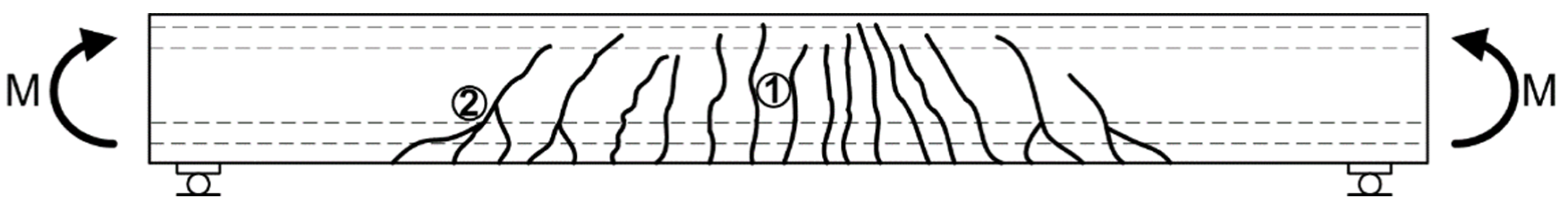
Cracks from bending:
Cracks from bending, which also causes tensile stresses at the points of their initiation, arise just in this part of the concrete cross-section and, propagating, tend to occur before the zone of zero tensile stresses [137] (Figure 6). In heavily reinforced elements, despite typical single perpendicular cracks or only slightly curved cracks (1), collective cracks (2) can also be observed (Figure 6).
(c)
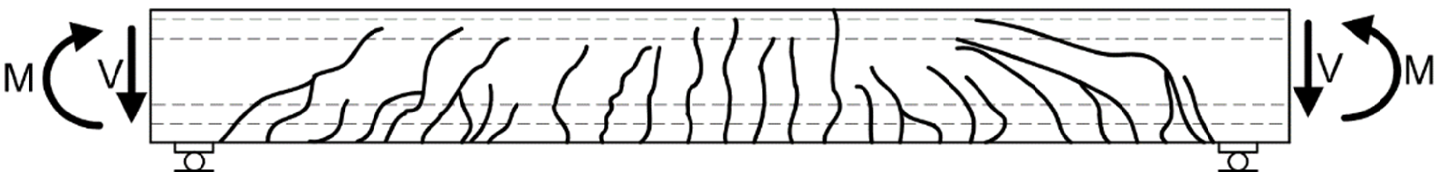
Cracks due to shear:
Cracks from shear are caused by inclined main tensile stresses. Their occurrence is caused by the occurrence of transverse forces. As shearing is a complex phenomenon that occurs as a result of the interconnected impact of the transverse force (V) and bending moment (M), the crack pattern occurring on the surface of the reinforced concrete element always depends on each of these internal forces in the concrete cracking process.
For this reason, in the middle zone of the element, where the influence of transverse forces is limited and the effort of the sections is determined by the bending moment, there are cracks perpendicular to the beam axis (Figure 7). However, in the support zone, where the transverse force has a dominant role in shearing, there are cracks inclined to the longitudinal axis of the bar (so-called diagonal cracks) [138] (Figure 7). Often, such cracks develop from previously formed cracks due to bending, as shown in Figure 6.
(d)
Cracks due to torsion:
In the case of torsion of reinforced concrete elements, which are a rather small group of reinforced concrete structures (such as edge floor joists, balcony slab ring beams, spatial frames, spiral stairs, and reinforced concrete arches loaded perpendicularly to their plane [139,140]), there arises shear stress (τT) in the cross-sections of the elements due to the torsional moment (T). These stresses may cause the formation of cracks that have a characteristic shape similar to a helix, wherein the line is inclined at an angle of 45° to the axis of the torsion element. Cracks with this type of stress characteristically occur on all surfaces of the reinforced concrete element. Their beginning, however, starts on the side surface along the longer edge of the element’s cross-section [141]. As the load increases, cracks begin to appear on the surface along the shorter edge. At the next stage of crack development, they also arise on the opposite longer edge. In the final phase of the development of cracks from torsion, they merge so that the crack grid covers all surfaces of the bar before the element is destroyed [142] (Figure 8). This helps to distinguish between cases where cracks result from shear in the structure and cases where cracks are caused by torsion [143,144]. As shown in Figure 7, in the case of shearing, cracks similar in shape (i.e., inclined at some angle to the longitudinal axis of the element) occur only on the side surface of the beam.
(e)
Summary and comparison of macroscopic crack morphology in reinforced concrete elements:
It should be noted that cracks in reinforced concrete elements occur when the concrete reaches the limit of tensile strength. Depending on the type of reinforced concrete structure, they occur in specific sections and zones of construction. Cracks in structural elements may differ both in shape and the direction of propagation and are related mainly to the type of interaction causing the formation of a given type of crack. There are four basic types of interactions in reinforced concrete structures, which result in cracks that differ from each other by shape, location, and propagation trajectories. Therefore, based on the information provided in the above subsections, Table 4 summarizes the relevant data corresponding to cracks resulting from different types of interactions in reinforced concrete structures.

4.2.2. Characteristics of Microcracks Correlated with the Type of Stresses Occurring in the Damaged Element

Apart from the characteristic pattern of cracks on the surface of reinforced concrete elements indicating almost unambiguously which type of load caused their formation, the type of stresses that led to the destruction of concrete can also be diagnosed on the basis of the appearance of the microstructure of its defects. Figure 9 shows characteristic arrangements of microcracks corresponding to cases of macroscopic damage caused by the basic types of stresses (Figure 5, Figure 6, Figure 7 and Figure 8). The presented cracks mainly concern the area of the ITZ phase, i.e., the weakest and main place of microcrack initiation in the concrete composite, as mentioned in Section 4.1. In order to present the differences between the various types of microcracks as accurately as possible, the photos selected have the same scale and magnification.
In structures where tension predominates, cracks are usually rectilinear in shape. They appear most often in the ITZ area and develop successively along the entire length of aggregate grains (Figure 9a). As the load increases, they may propagate into the structure of the cement matrix or into the depth of an inclusion, as is the case where the matrix is characterized by greater strength than that of the coarse aggregate, such as in high-performance concretes [145].
As in the macroscopic approach, shear stress causes straight cracks to curve and also causes curves at the ends of microcracks to begin to appear, with the direction of their propagation also changing. In the vertices of simple microcracks, wings are initiated (Figure 8b). Depending on the value of the present loads, the wings may deviate at a greater or lesser angle to the straight section of the microcrack. Change in both the morphology and the trajectory of such microcracks may cause the aggregate grains to lose their local cohesion with the matrix surface, which may lead to their separation from its surface. Cavities are then formed in the concrete structure. The characteristic shape of the wing microcrack, which is the result of shear, is observed at the place where the aggregate grain crumbles out of the paste (Figure 9b).
In turn, torsion, which in the macroscopic approach causes the formation of spatial cracks on several surfaces of the structural element (Figure 8), also changes the shape of microcracks in the concrete structure. As a result of the existing state of stress, the tips of the wings are twisted, often combined with additional local micro-damages at stress concentration points, i.e., in places where straight segments of microcracks curve (Figure 9c). Other arrangements of microcracks due to torsion that have been observed include microcracks propagating radially from the center of the sample towards its outer edge [146] and damage in the shape of a semicircle [147].

5. Detection and Observation of Cracks and Microcracks in Concrete

5.1. The Core of the Problem in the Field of Concrete Cracking Research

Randomness of the geometric arrangement, the size and shape of concrete composite filler grains, and variability in its mechanical and physical properties—both in relation to the adjacent grains and the cement matrix—make analysis of the concrete cracking process a difficult task. Hence, the process of the formation and development of microcracks and cracks in concrete has, for a long time, been concluded only on the basis of external symptoms and effects, such as deformability under load. With the development of numerous measurement techniques, there opens up the possibility of not being limited to certain average values (e.g., stresses, deformations), but instead searching for the causes of damage formation and propagation due to no longer being confined to analyses of the effects of the destruction processes occurring in concrete. For these reasons, there has been a rapid development of techniques and devices used for detecting microcracks and assessing their propagation over the last few decades [148].
Depending on the adopted reference scale, the accuracy of observations, and the assumed research objectives, various methods are available that can be used to detect and analyze cracks and microcracks in concrete.
Therefore, the characteristics and the advantages and disadvantages of the most commonly used methods and devices used for localization and analysis are given below:
  • Cracks on the concrete surface;
  • Microcracks located inside the concrete structure.

5.2. Diagnostics of Surface Cracks

Tools for identifying and observing cracks occurring on the surface and in the microstructure of composites with cement matrices have been successively developed since the 1960s. However, in recent years, due to the alarmingly deteriorating state of the world’s concrete infrastructure, particular emphasis has been put on the development of non-destructive methods that could be used in the diagnosis of structures, as well as in the recognition and analysis of the degree of their defects [149]. For this purpose, attempts were made to adapt new non-destructive techniques for assessing the structure of materials that previously had been effectively used in medicine, the aviation industry, geotechnics, and metal research, among others [150].
In the case of damage occurring on the surface of concrete elements, width is of special importance because large-width cracks can significantly reduce the stiffness, strength, and tightness of the structure. This, in turn, can cause progressive corrosion of the reinforcement bars. For this reason, the opening width of such cracks is usually standardized within the range of 0.2–0.4 mm. However, for structures working in aggressive environments, and those with tightness requirements, the limit norm of cracks is only 0.1 mm [151]. Additionally, the diagnostic methods used to assess surface and subsurface cracks have a large range of various partially standardized measuring tools. The techniques used can be generally divided into non-destructive, semi-non-destructive, and destructive, while the most commonly used are visual tests, the ultrasonic method, and more modern methods used recently in the analysis of surface cracks, i.e.:
  • Thermographic methods;
  • Digital image correlation (DIC).
A description of the thermography method, with an example of a thermal imaging camera used for the analysis of near-surface cracks in a bent element, is presented in [152,153,154]. This methodology includes initial scanning of the concrete surface by the infrared camera at the time of maximum heat exchange between the structure and the environment after direct sunlight. The information from the temperature field (local fluctuations), as well as the cooling down curve (different rate of cooling relative to the neighboring areas), will indicate subsurface defects [152]. This technique is especially successful in the detection of cracks in “troublesome” areas. In addition, this method could be used in the evaluation of concrete delamination in some concrete structures [155], as well as in damage detection in composite materials [156]. Recently, novel methods of testing defects in buildings have appeared, such as time-lapse thermography [157] parallel to the traditional thermographic technique.
It should also be noted that, in the literature, one can find numerous examples of the use of the thermographic method in the assessment of adhesion defects caused by the development of cracks in concrete reinforced with CFRP fabrics [158]. This technique has also been used for this type of experiment in conjunction with other non-destructive methods [159]. The benefits of using this method of locating damage were also observed when detecting cracks in ceilings [160] and elements of road infrastructure [161].
The DIC technique, on the other hand, is designed for non-contact measurement of displacements and crack assessment in flat and spatial concrete elements subjected to load [162]. It is a non-invasive optical method that consists of taking a series of photos of the analyzed area of the tested structure under various loads and then analyzing the photos taken. Such activities are aimed at calculating the displacements of selected points of the analyzed area [45,163,164].
The measuring system in the DIC technique consists of a set of cameras recording changes in the shape of the examined object and a suitably adapted and programmed computer that stores and processes the recorded images. Depending on the configuration, i.e., the number and speed of the cameras, the system can be used to analyze the displacement and deformation fields of flat or spatial elements loaded statically or dynamically. Thanks to the analysis of photos taken along with the progressing loading process, it is possible to identify cracks in unreinforced and reinforced concrete elements. This advanced and very precise technique of detecting macrocracks is also useful in the study of microcracking processes in the concrete structure [165]. Thanks to the exceptional precision of this method, it is possible to analyze cracking processes in concretes subjected to exposure not only to mechanical loads [166], but also to other types of loads, e.g., thermal loads [167]. The unique qualities of the DIC technique also allow for accurate tracking of the development of microcracks and cracks in the concrete structure [168].
According to [169], the DIC technique also allows for the visualization and quantification of the fracture properties of reinforced concrete. Moreover, the DIC technique was found to be an effective means for measuring crack opening displacements [170,171]. On the other hand, the Crack Tip Tracking (CTT) method developed by [172] helps, among others, to determine the highly approximated total length of microcracks despite the fact that its complicated and complex trajectory is located inside the damaged structure of the material. Such studies allow for later conclusions to be drawn about the difference between the behavior of different types of materials in the process of their damage [173].
Based on the above data, Table 5 provides a comparison of the advantages and disadvantages of the thermal imaging method and the DIC method [174,175].

5.3. Detection of Structural Microcracks

5.3.1. General Division of the Diagnostic Methods Used

Contrary to surface cracks, the width of microcracks that occur inside the concrete structure is not limited by any standards. Neither are there any adopted uniform standards for their detection and observation. In the literature, one can find numerous available methods to identify microcracks in concrete elements, which are classified on the basis of various criteria.
According to [173], the methods of detecting cracks in concrete can be divided into three categories, i.e., radiography, replica, and impregnation categories, while according to [176], such tests include microscopic, acoustic, and radiographic methods. One of the methods of locating internal cracks in material proposed by the author of [177] is also based on acoustic phenomena. Moreover, the study of microcracks in concrete can be conducted basing on interferometry techniques [178].
It should be noted that some of the available methods of microcrack analysis described above have been modified and successively developed over recent years. To illustrate this, Figure 10 presents (in several subgroups) most of the methods used to track and observe damage in a concrete structure. In the classification prepared, emphasis is placed on well-known methods of crack analysis (e.g., X-ray and neutron radiography), as well as those containing new potential as measurement techniques in crack analysis (e.g., the possibility of spatially modeling damage in concrete using computer tomographs [126,179,180,181,182] or magnetic resonance imaging [183,184]). Additional detailed information on each of the measurement techniques presented in Figure 10 can be found in the selected literature added to the presented classification (Figure 10). Below, a brief description and historical outline of the most characteristic and important diagnostic methods is also included.

5.3.2. Radiographic Methods

Most of the methods listed in Figure 10 have been known for several decades, such as microscopic, radiographic, ultrasonic, and acoustic emission methods. One of the first methods of analyzing microcracks in concrete was radiographic examination. This method was introduced in the early 1960s by Stale and Olsefski [185] and consisted, similarly to its use in medicine, of recording the weakened radiation intensity γ or X that penetrated the analyzed concrete element. Taking recourse to the principles of “brightness” and “shading” used in radiography and X-ray image analysis, it was possible to estimate which parts of concrete samples had discontinuities in the material structure in the form of pores or cracks. Such areas in the photographs taken were characterized by black points or lines, which indicated that the radiation in this area was not absorbed by the sample and could reach the photographic film through the void in the concrete. In the 1980s and 1990s, Otsuka made a significant contribution to the analysis of cracking processes in concrete using the radiographic method. In his research, he mainly dealt with assessment of the fracture process zone’s [186] development before the microcrack tip and the impact of maximum aggregate grain size (Dmax) on its size and structure. On the basis of the photographs taken, he determined that even before the clear break on the curve force (F), known as crack mouth opening displacement (CMOD) or F-CMOD, the beginning of damage development is already visible. In addition, the value of cracking energy increases proportionally to the size of the coarse aggregate used.
In order to analyze the fracture process zone in concrete elements even more thoroughly, the authors of [187] used a spatial acoustic emission analyzer together with the radiographic method with contrast. Interpretation of the results obtained from both measuring devices showed that, as load increases, the fracture process zone consists of numerous cracks, and the effects of their development are accompanied by AE events. In addition, with increases in the Dmax of concrete, the width of the cracking zone also increases, while its length decreases. Thus, it is shorter; however, it occupies a larger volume in the structure of the damaged material [187]. The main advantage of the X-ray radiography method is the ability to visualize discontinuities occurring in the material and perform visual assessment. However, concrete defects such as cracks, pores, and honeycombs can only be analyzed in flat images and only in directions favorably oriented to the wave beam. A further disadvantage of the radiographic method is its poor resolution and low sensitivity when detecting defects.
Another important step in the development of tools for assessing the distribution of defects in concrete was the development of a radiographic method involving the use of active neutrons instead of X-rays (Figure 10a). Over time, neutron radiography, as a more accurate method and more sensitive to the identification of microcracks in concrete, has become a much more competitive method for image mapping than X-ray radiography. This is mainly due to the fact that the images obtained in studies using neutrons are of much better quality and sharpness than the results obtained with the older radiographic method. According to [188,189,190], the neutron radiography method is useful in assessment of concrete damage and is more effective than the traditional X-ray radiography method. Currently, neutron radiography is used not only in construction and nuclear research, but also in biology and the aircraft and missile industries.
The higher sensitivity and greater possibilities of the neutron radiography method in relation to the X-ray radiography method in the context of identifying microcracks in the concrete structure are also evidenced by the results of the research presented in [191]. They show that the minimum size of a defect that can be identified by neutron radiography is 25 times smaller than the damage visible in X-ray radiography images. In addition to testing the size of internal microcracks in concrete, the neutron radiography method has also found wide application in assessment of the durability of composites through measurements of the penetration of water or aggressive substances into their structure [192,193]. According to [192], this is an excellent way to assess the penetration of media through concrete because they weaken neutrons much more than the basic components forming its structure, i.e., cement and aggregate. Such tests are particularly important in reinforced concrete structures because a sudden transport of moisture or corrosive agents can lead to the rapid destruction of reinforcements and to the occurrence of emergency conditions in the structure. An example of how the neutron radiography method is used in the assessment of water penetration into the area of reinforcement bars is provided, among others, by [193].

5.3.3. Microscopic Observations

Microscopes have been used for careful observation of microcracks occurring in concrete structures for many years. Among the electron microscopes commonly used, the scanning electron microscope (SEM) (Figure 10b) has the greatest advantages for the analysis of microcracks [194,195]. According to [196], an SEM is one of the most versatile instruments available for the examination and analysis of the microstructural characteristics and defects of solid objects, whereas, according to [197], an SEM is the main tool for the evaluation of concrete microstructures. The method of observing the cracking and fracture processes in concrete by means of an SEM is frequently applied to assess the impact of the initial structure of the composite or the type of prevailing loads on the size of the occurring damage [198], as well as to assess the degree of defects in materials exposed to corrosive agents [199]. Figure 9 presents various types of microcracks visible in the SEM images depending on the type of stress inducing them.
Currently, in order to conduct more advanced research on the structure of cracks in concrete and to learn the exact causes of their initiation, new advanced types of electron microscopes are used, such as TEM, ESEM, and modern AFM microscopes (Figure 10b). These microscopes are widely employed as one of the most important imaging techniques for the atomic analysis of interfaces, structures, and chemical compositions in cement concretes [200,201,202]. Thanks to their use, it is possible to diagnose damage while taking into account the type of concrete composite phase and to estimate the orientation of the crack in relation to the direction of fibers in the analyzed phase, e.g., C-S-H phase [203,204].
Diagnosis of damage and microcracks in concrete elements can also be carried out with microscopes of other types, e.g., traditional optical microscopes [173,205] (Figure 10b). In [173], a thorough analysis of geometric parameters characterizing cracks at the mesoscale level was presented, including length, width, surface area, and density. The results presented in [173] also showed good correlation between crack density and concrete compressive strength.

5.3.4. Methods Using Acoustic Waves

Another group of methods used to analyze the development of microcracks in concrete are techniques based on acoustic phenomena. These include the ultrasonic method and the acoustic emission method (AE) (Figure 10c).
Ultrasonic methods have been used for many years as a non-destructive method for the assessment of concrete strength. They also have the advantage of being able to detect internal defects in the structure and are even able to estimate their size with a high degree of approximation. Ultrasonic methods are so accurate that they are used to determine subtle differences in the measurements performed, such as the type of load causing cracks (cracks occurring as a result of bending or shearing) [206] or differences in the length of the microcrack [207]. The ultrasonic method can be used to analyze the development of damage not only in loaded concrete, but also in mortars and pastes.
Another method applying acoustic phenomena in the study of concrete microcracks is the AE method. It is based on the phenomenon of the formation and propagation of elastic waves in a given medium, which arise in the material as a result of the release of stored elastic energy. One of the reasons for the occurrence of AE in construction materials is the initiation and development of microcracks appearing in cracking processes. The beginning of research on the relationship between AE and the development of damage in concrete is assumed to be the year 1970, when Green conducted comprehensive experiments that clearly demonstrated the relationship between the generated AE signal and the development of damage in a loaded concrete element [208].
Currently, the spectrum of applications of the AE phenomenon in the study of defects in concrete composites is quite wide. AE analyzers are mainly used in laboratory tests, which include, among others, assessment of critical stress levels in concrete [209], tests of the fracture toughness of concrete in Type-I, Type-II, and mixed-mode fractures [210,211,212], and analysis of the impact of curing time on the development of destructive processes in concrete [213]. Thanks to this method and on the basis of analysis of the values of specific parameters, it is also possible to draw conclusions about the stage of damage development in the material. On this basis, in [214], the following stages of damage development in concrete were identified:
  • Micro-cracking before the main fracture;
  • The main fracture;
  • After main fracture.
The AE phenomenon is not only used in laboratory tests, but also in the assessment of damage and cracks in facilities and engineering structures, mainly bridges [215].

5.3.5. Methods Based on Interferometry Phenomena

In the 1980s and 1990s, methods based on the phenomenon of electromagnetic wave interference were very popular in detecting external damage in concrete (Figure 10d). The main assumptions regarding holography, and other methods based on interferometry applied to the study of deformation of concrete elements, were presented by Jacquot and Rastogi in one of the chapters of their monograph on the mechanics of concrete cracking [216].
Interferometry is a group of methods that includes holography, speckle interferometry, moiré interferometry, and others (Figure 10d), which are used in experimental mechanics to observe the displacement of structural elements. In this type of research, in the initial stage, the surface of the tested object is illuminated with a carrier wave beam that is treated as the primary signal; in the case of holography, the so-called stripe pattern is created. As a result of changes in the surface of the tested element subjected to loads, disturbances in the original signal then occur. Locating and analyzing anomalies in the light beam may be the basis for detecting even minor damage.
Interferometry has been applied to locate cracks in both concrete elements [217,218] and reinforced elements [220], which could be observed even in real time [217]. A comprehensive review of publications describing the use of the above methods in researching the destructive processes of concrete was presented by Maji in [177].

5.3.6. Methods Using Tomographs

Computerized tomography is an effective way to accurately visualize defects occurring inside the concrete structure (Figure 10e). This non-invasive method allows for cross-sections of the examined element to be obtained by assembling projections of the object made from different directions. The result of the conducted tests may be 2D flat images or 3D spatial images. A more advantageous solution is to obtain, as a result of the tests, three-dimensional tomograms that allow for accurate localization of the smallest material defects in the entire volume of the tested sample.
The first studies of concrete structures using computerized tomography were carried out in the early 1980s [181]. The information presented on three-dimensional tomograms was also used to assess the location of reinforcements in reinforced concrete elements [179]. Over time, this section of non-destructive testing of concrete has become so important that an entire chapter in the fifth part of the monograph is devoted to describing the advanced experimental techniques used for testing concrete composites with this method [180]. Currently, computer tomographs are used to assess the degree of defects in the microstructure of concrete exposed to adverse weather conditions or corrosive factors. The authors of [182] present the results of tests assessing the level of damage in concrete exposed to cyclic freezing and thawing.

5.3.7. Other Effective Methods Used for the Detection and Analysis of Microcracks

In recent years, methods based on the assessment of surface fractures in damaged concrete elements have also been used to analyze cracking processes in concrete. This type of technique includes stereology, fractography, and impregnation (Figure 10f) [220,221,222,223,224,225,226,227,228,229,230,231,232]. At present, these methods are used, among others, for the analysis of surface cracks in concretes and mortars subjected to exposure to high temperatures [223].
Numerical simulations, as well as artificial intelligence methods, are also an effective tool in the analysis of the microcrack and crack propagation process [224]. Here, particularly favorable results were obtained with the extended finite element method (XFEM) [225,226] and machine learning (ML) techniques [227,228] (Figure 10f).
At this point, it is worth underlining that the widely understood AI systems, which are currently being developed on a large scale, are new computational tools that cover a wide range of issues. However, among the most frequently used techniques based on these new measurement possibilities, the following methods can be distinguished [229,230,231,232]:
  • Fuzzy sets;
  • Approximate sets;
  • Artificial neural networks;
  • Machine learning;
  • Evolutionary calculations;
  • Genetic algorithms;
  • Artificial life;
  • Robotics.
In analysis of the formation and propagation of cracks in concrete elements and structures, AI methods are mainly used in situations where problems related to the creation of mathematical models that allow complex relationships between input signals and selected output signals to be mapped appear. Growing interest in these heuristic systems is also due to the possibility using them when standard methods fail or are not very effective [233].
It should also be added that, recently, methods for diagnosing damage and cracks in concrete structures based on non-invasive techniques, the so-called non-destructive techniques (NDTs), have been widely developed. In general terms, the NDTs used in concrete and reinforced concrete structures are mainly used to detect discontinuities in the concrete structure. In addition to the methods already well known and used for many years in this field, such as the sclerometric, ultrasonic, radiological, pull-out, and pull-off methods, there are also modern and recently used NDTs that use various types of sensors during research. These include NDTs such as:
  • Sweep frequency [234];
  • Ground penetration [235];
  • Techniques using infrared [236];
  • Techniques using fiber optic sensors [237];
  • Techniques using cameras [238];
  • Techniques using laser monitoring systems [239].
Assessing the possibilities and existing limitations of the above measurement methods, it can be concluded that these modern and useful NDTs have the following characteristics [240]:
  • They provide very accurate measurement results;
  • They minimize the costs of additional monitoring of the cracking process in the structure by reducing the need to use it;
  • They reduce the time needed to carry out the diagnostic process;
  • They can minimize the number of sudden failures resulting from uncontrolled cracking development because they provide accurate, specific, and invisible data in real time, e.g., data related to the development of the microcracking process in the material structure or the corrosion of reinforcing bars in a reinforced concrete element.

5.4. Conclusions Resulting from the Review of Methods Used to Detect Cracks and Microcracks in Concrete Elements

It should be noted that most of the currently known and used methods for the observation of defects in concrete and concrete elements and structures (Figure 10) can only be used in an effective manner if they are applied after being closely correlated with the scale of observation of a given defect in the material. Therefore, based on [241], Figure 11 shows most of the diagnostic methods previously described, with some significant details added. The measurement methods were assigned to appropriate scales in terms of which are capable of tracking damage in the concrete structure effectively. The diagram has been thought of as an overview of the majority of the available methods in the field of microcrack and crack assessment, beginning with the methods used for observation of material structures at the molecular and nanoscale level and ending with measurement techniques used in macroscale structures.
It is worth mentioning that, in order to achieve the intended effect of the experiment and properly estimate the size and morphology of the microcracks or cracks, an appropriate damage analysis technique should be selected. It should be characterized by the following parameters [242]:
  • It should be relatively economical;
  • It should detect defects quickly;
  • It should be characterized by high resolution, i.e., capable of detecting very small microcracks;
  • It should provide quantitative information readily associated with an image analysis system.
In addition, the choice of the method for crack observation should depend on the type of prevailing loads (static, dynamic, impact). It is then possible to detect even a very subtle difference in the obtained research results. For example, in [208] and based on the analysis of images obtained under an optical microscope, it was determined that the lengths of cracks in the ITZ of concrete subjected to fatigue loads are 15% greater than cracks occurring in the elements subjected to static loads.
Often, in order to assess the occurring damage accurately, two or even three research methods are used in parallel, such as a combination of radiographic methods, laser holography, or computerized tomography with AE or SEM [178,182,218,242,243]. In many cases, AE or thermography with the ultrasonic method is used to analyze the location of damage and the directions of its propagation [206,214].
Very good results in terms of the detection of concrete microcracks were also obtained by combining the AE and DIC techniques [244,245] or AE with computational geometry [246]. It was found that the AE technique is useful in identifying the location of fracture growth due to microcracks and macrocracks; however, DIC is useful in measuring crack openings at their various locations. Moreover, the location of the crack tip is also estimated with both techniques [247].
An accurate picture of cracking paths is obtained by juxtaposing several independent concrete crack-tracking devices. For this purpose, a test stand consisting of an AE analyzer, a computer microtomograph, and an SEM can be used [242]. During the analysis of the structure of concrete samples, the AE sensor locates the damage occurrence, the tomograph enables spatial scanning of the resulting defects, and the microscope takes photos of the microstructure of the damaged material [242].
Currently, having computer tomographs applied, it is possible to precisely recognize the structure of microcracks in the three-dimensional space of the sample. Subsequently, by using the program to visualize the detected damage, an accurate spatial image of discontinuities occurring in concrete is generated [248].
It should also be noted that recently, in the field of crack diagnosis in concrete elements, NDTs have also been developed. AI-based methods are also being used more and more often in such research.
When summarizing the characteristics of the methods that allow for effective diagnostics of the process of microcracking and cracking in elements made of concrete, it should be stated that all the techniques presented in Figure 10 and Figure 11, and briefly characterized in the text, confirm the progressive process of microcrack initiation and the phenomenon of their multiplication and successive propagation alongside increasing load. Moreover, due to different ways of detecting defects and different degrees of sensitivity, these measurement methods can be used to identify microcracks and to analyze the effects of cracks in very different types of brittle composites and at different intensities of occurring stresses [186].

6. Final Remarks

The strength and durability of concrete structural elements is largely determined by defects and damage occurring in the structure of first young and then mature concrete. This is due to the fact that weaker places in the concrete composite cause the concentration of stresses and facilitate the penetration of various external factors. In the locations where microcracks and cracks propagate, strength decreases, with local material destruction and emergency conditions thus occurring. Therefore, the issues dealt with in the article concern important aspects related to both the safety and serviceability of concrete structures. These problems are quite difficult to analyze because the cracking of concrete in structural elements results both from the specificity of reinforced concrete structures and from the properties of inherent composites within a cement matrix.
Therefore, the article provides an in-depth review of issues related to the process of the formation and propagation of microcracks and cracks in cement concretes. The content of the dissertation focuses mainly on the reasons for the formation of microcracks in the material structure, the basic criteria classifying these defects, and the most commonly used methods for their detection and analysis.
There are two types of causes of damage in concrete and reinforced concrete elements, namely:
  • Primary defects—resulting from the natural properties of the material or from design and execution errors;
  • Secondary defects—occurring during construction exploitation.
At this point, particular attention was paid to the danger of initiating microcracks in the initial period of concrete curing, i.e., at an early age. The materials most exposed to this phenomenon are massive concretes and high-performance concretes. It was also established that it is possible to limit these adverse phenomena by modifying the binder of such concretes with fly ash.
In the analyses, the types of cracks occurring in concrete composites were divided according to eight specific criteria. The images of cracks occurring macroscopically in reinforced concrete elements were studied depending on the type of prevailing loads, and characteristic images of microcracks correlated with a specific case of macrocracks were then extracted.
Due to the lack of complete data regarding the relationship between the trajectories of macrocracks and the morphology of microcracks occurring in the structure of the material, proprietary microscopic analyses of the damaged structures were carried out. Structural elements damaged due to stretching, shearing, and torsion were considered. As a result of the conducted analyses, the following has been established:
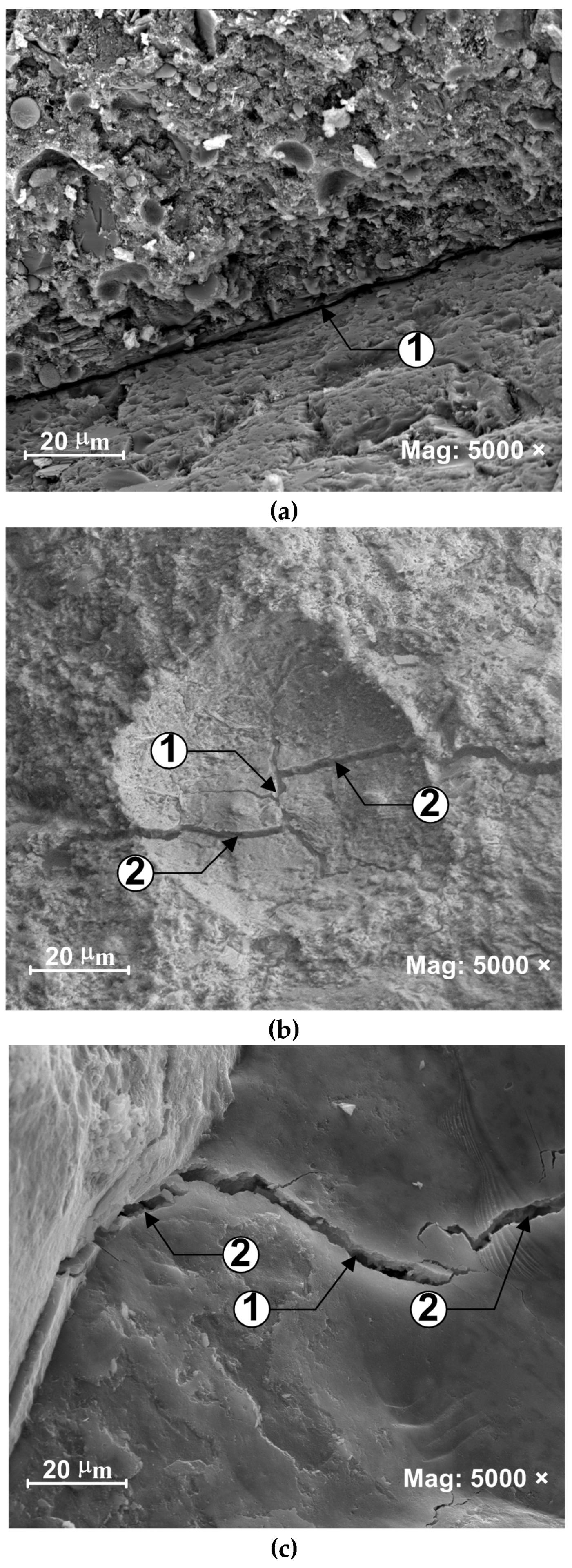
  • In tensioned elements, microcracks are usually rectilinear in shape and occur primarily in the ITZ area (Figure 9a);
  • In shear elements, there are wing-type microcracks with straight wings that deviate at different angles from the plane of the straight section of the microcrack (Figure 9b);
  • Torsional stresses cause changes in wing microcrack morphology. While twisting, the tips of the wings are twisted, and the concrete at the connection with the straight part of the microcrack, i.e., places of stress concentration, is evidently crushed (Figure 9c).
In the second part of the manuscript, a broad review of diagnostic methods used to locate and describe the propagation directions of cracks and microcracks in concrete was performed. Both traditional and well-known measurement methods, as well as modern and constantly developing diagnostic methods, were taken into account. It has been determined that the first damage in concrete structures can be detected via one of several diagnostic methods (Figure 10). The most common methods include microscopic, acoustic, radiographic, and fractal methods, as well as those involving computerized tomography. On the other hand, thermography and DIC belong to the group of modern methods used to analyze cracks on the surface of concrete elements. However, it should be added that the DIC technique is also effectively used in the process of tracking microcracks.
With regard to these two useful and relatively new diagnostic methods, a comparison of their advantages and limitations in relation to their use was made. On this basis, it was found that the main advantages of both thermography and the DIC method are the non-contact method of conducting measurements and the possibility of locating damage regardless of the dimensions of the structural element. Unfortunately, their disadvantages include the complicated mathematical algorithms used to generate specific results from the experiments. In case of the DIC method, preparation of samples for testing is also problematic. However, this is compensated by very accurate results in the conducted experiments and reductions in the costs related to the procedure of damage measurement.
In addition, based on the review of the latest literature in this field, it has been found that, in the field of crack diagnostics in concrete elements, NDTs have undergone significant development in recent years. Several brand new and useful ways of detecting defects in materials have emerged in this area. It has been established that modern diagnostic tests in this area include the use of methods such as sweep frequency and ground penetration, as well as those using infrared, fiber optic sensors, or laser monitoring systems. Moreover, methods based on the phenomenon of AI are also increasingly used.
In order to entirely understand the processes of the formation and propagation of microcracks and cracks in concrete, it is recommended to combine two or even three measurement methods at the same time. In the future, such studies could help to sharpen the criteria of the initiation and propagation of cracks, to predict the direction of the growth of cracks, and to analyze complex problems related to the propagation of cracks.
It should be noted that the subject matter of microcracks and cracks in concrete and structures made of concrete is important in many respects as it concerns, in a holistic approach, the durability of buildings, the safety of people staying indoors, and costs related to possible repairs to damaged structural elements. Therefore, this topic calls for further studies concerning the development of modern non-destructive measurement techniques that can be used for precise analysis of the formation and propagation of cracks in the material. These techniques would enable the diagnosis of primary defects long before they change into macroscopic damage and eventually cause form change in concrete. Such an approach would prevent the need for costly repairs to damaged elements.

Funding

This work was financially supported by Ministry of Science and Higher Education of Poland within the statutory research number FN-15/ILTIG/2023.

Data Availability Statement

No new data were created or analyzed in this study. Data sharing is not applicable to this article.

Conflicts of Interest

The author declares no conflict of interest.

References

  1. Pacheco-Torgal, F. High Tech Startup Creation for Energy Efficient Built Environment. Renew. Sustain. Energy Rev. 2017, 71, 618–629. [Google Scholar] [CrossRef] [Green Version]
  2. Golewski, G.L. The Specificity of Shaping and Execution of Monolithic Pocket Foundations (PF) in Hall Buildings. Buildings 2022, 12, 192. [Google Scholar] [CrossRef]
  3. Kovacik, J.; Marsavina, L.; Linul, E. Poisson’s Ratio of Closed-cell Aluminum Foams. Materials 2018, 11, 1904. [Google Scholar] [CrossRef] [Green Version]
  4. Lata, P.; Kaur, I. Thermomechanical Interactions in Transversely Isotropic Magneto Thermoelastic Solid with Two Temperatures and Without Energy Dissipation. Steel Compos. Struct. 2019, 32, 779–793. [Google Scholar]
  5. Khaji, Z.; Fakoor, M. Strain Energy Release Rate in Combination with Reinforcement Isotropic Solid Model (SERIS): A new Mixed-Mode I/II Criterion to Investigate Fracture Behavior of Orthotropic Materials. Theor. Appl. Fract. Mech. 2021, 113, 102962. [Google Scholar] [CrossRef]
  6. Craciun, E.M. Energy Criteria for Crack Propagation in Prestresses Elastic Composites. Sol. Mech. Appl. 2008, 154, 193–237. [Google Scholar]
  7. Suchorab, Z.; Franus, M.; Barnat-Hunek, D. Properties of Fibrous Concrete Made with Plastic Fibers from E-Waste. Materials 2020, 13, 2414. [Google Scholar] [CrossRef]
  8. Golewski, G.; Sadowski, T. Fracture Toughness at Shear (Mode II) of Concretes Made of Natural and Broken Aggregates. Brittle Matrix Compos. 2006, 8, 537–546. [Google Scholar]
  9. Li, H.; Sun, H.; Zhang, W.; Gou, H.; Yang, Q. Study on Mechanical Properties of Self-Compacting Concrete and its Filled in-line Multi-Cavity Steel Tube Bundle Shear Wall. Energies 2019, 12, 3466. [Google Scholar] [CrossRef] [Green Version]
  10. Abolhasani, A.; Nazarpour, H.; Dehestani, M. Effects of Silicate Impurities on Fracture Behavior and Microstructure of Calcium Aluminate Cement Concrete. Eng. Fract. Mech. 2021, 242, 107446. [Google Scholar] [CrossRef]
  11. Saini, G.S.; Erge, O.; Ashok, P.; van Oort, E. Well Construction Action Planning and Automation through Finite-Horizon Sequential Decision-Making. Energies 2022, 15, 5776. [Google Scholar] [CrossRef]
  12. Fakoor, M.; Rafiee, R.; Zare, S. Equivalent Reinforcement Isotropic Model for Fracture Investigation of Orthotropic Materials. Steel Compos. Struct. 2019, 30, 1–12. [Google Scholar]
  13. Bao, H.; Peng, J.; Cheng, Z.; Hong, J.; Gao, Y. Experimental Study on Inner Interface Mechanical Properties of the ESDCM Pile with Steel Core. Buildings 2023, 13, 486. [Google Scholar] [CrossRef]
  14. Golewski, G.L. Green Concrete Based on Quaternary Binders with Significant Reduced of CO2 Emissions. Energies 2021, 14, 4558. [Google Scholar] [CrossRef]
  15. Kang, S.-H.; Kwon, Y.-H.; Moon, J. Quntitative analysis of CO2 uptake and mechanical properties of air lime-based materials. Energies 2019, 12, 2903. [Google Scholar] [CrossRef] [Green Version]
  16. Szcześniak, A.; Zychowicz, J.; Stolarski, A. Influence of Fly Ash Additive on the Properties of Concrete with Slag Cement. Materials 2020, 13, 3265. [Google Scholar] [CrossRef]
  17. Wardach, M.; Krentowski, J.R.; Mackiewicz, M. Evaluation of Precast Beam Deflections Resulting in Cracks in Curtain Walls. Eng. Fail. Anal. 2022, 140, 106568. [Google Scholar] [CrossRef]
  18. Chen, S.; Wang, H.; Guan, J.; Yao, X.; Li, L. Determination Method and Prediction Model of Fracture and Strength of Recycled Aggregate Concrete at Different Curing Ages. Constr. Build. Mater. 2022, 343, 128070. [Google Scholar] [CrossRef]
  19. Guan, J.; Yin, Y.; Li, Y.; Yao, X.; Li, L. A Design Method for Determining Fracture Toughness and Tensile Strength Pertinent to Concrete Sieving Curve. Eng. Fract. Mech. 2022, 271, 108596. [Google Scholar] [CrossRef]
  20. Wu, J.; Yang, J.; Zhang, R.; Jin, L.; Du, X. Fatigue Life Estimating for Chloride Attacked RC Beams Using S-N Curve Combined with Mesoscale Simulation of Chloride Ingress. Int. J. Fat. 2022, 158, 106751. [Google Scholar] [CrossRef]
  21. Nikbin, I.M.; Golshekan, M. The Effect of Expanded Polystyrene Synthetic Particles on the Fracture Parameters, Brittleness and Mechanical Properties of Concrete. Theor. Appl. Fract. Mech. 2018, 94, 160–172. [Google Scholar] [CrossRef]
  22. Reis, J.M.L.; Chianelli-Junior, R.; Cardoso, J.L.; Marinho, F.J.V. Effect of Recycled PET in the Fracture Mechanics of Polymer Mortar. Constr. Build. Mater. 2011, 25, 2799–2804. [Google Scholar] [CrossRef] [Green Version]
  23. Wong, L.S.; Chandran, S.N.; Rajasekar, R.R.; Komg, S.Y. Pozzolanic Characterization of Waste Newspaper Ash a Supplementary Cementing Material of Concrete Clinders. Case Stud. Constr. Mater. 2022, 17, e01342. [Google Scholar]
  24. AL-Shalif, S.A.H.; Akın, A.; Aksoylu, C.; Arslan, M.H. Strengthening of Shear-Critical Reinforced Concrete T-Beams with Anchored and Non-Anchored GFRP Fabrics Applications. Structures 2022, 44, 809–827. [Google Scholar] [CrossRef]
  25. Aksoylu, C. Shear Strengthening of Reinforced Concrete Beams with Minimum CFRP and GFRP Strips Using Different Wrapping Technics without Anchoring Application. Steel Compos. Struct. 2022, 44, 845–965. [Google Scholar]
  26. Ozkilic, Y.O.; Gemi, L.; Madenci, E.; Aksoylu, C. Effects of Stirrup Spacing on Shear Performance of Hybrid Composite Beams Produced by Pultruded GFRP Profile Infilled with Reinforced Concrete. Arch. Civ. Mech. Eng. 2023, 23, 36. [Google Scholar] [CrossRef]
  27. Madenci, E.; Özkılıç, Y.O.; Aksoylu, C.; Safonov, A. The Effects of Eccentric Web Openings on the Compressive Performance of Pultruded GFRP Boxes Wrapped with GFRP and CFRP Sheets. Polymers 2022, 14, 4567. [Google Scholar] [CrossRef]
  28. Gemi, L.; Madenci, E.; Özkılıç, Y.O.; Yazman, Ş.; Safonov, A. Effect of Fiber Wrapping on Bending Behavior of Reinforced Concrete Filled Pultruded GFRP Composite Hybrid Beams. Polymers 2022, 14, 3740. [Google Scholar] [CrossRef]
  29. Aksoylu, C.; Özkılıç, Y.O.; Madenci, E.; Safonov, A. Compressive Behavior of Pultruded GFRP Boxes with Concentric Openings Strengthened by Different Composite Wrappings. Polymers 2022, 14, 4095. [Google Scholar] [CrossRef]
  30. Özkılıç, Y.O.; Aksoylu, C.; Yazman, Ş.; Gemi, L.; Arslan, M.H. Behavior of CFRP-Strengthened RC beams with Circular Web Openings in Shear Zones: Numerical Study. Structures 2022, 41, 1369–1389. [Google Scholar] [CrossRef]
  31. Arslan, M.H.; Yazman, Ş.; Hamad, A.A.; Aksoylu, C.; Özkılıç, Y.O.; Gemi, L. Shear Strengthening of Reinforced Concrete T-beams with Anchored and Non-Anchored CFRP Fabrics. Structures 2022, 39, 527–542. [Google Scholar] [CrossRef]
  32. Gemi, L.; Alsdudi, M.; Aksoylu, C.; Yazman, Ş. Optimum amount of CFRP for strengthening shear deficient reinforced concrete beams. Steel Compos. Struct. 2022, 43, 735–757. [Google Scholar]
  33. Özkılıç, Y.O.; Yazman, Ş.; Aksoylu, C.; Arslan, M.H.; Gemi, L. Numerical Investigation of the Parameters Influencing the Behawior of Dapped end Prefabricated Concrete Purlins with and without CFRP Strengthening. Struct. Constr. Build. Mater. 2021, 275, 122173. [Google Scholar] [CrossRef]
  34. Pathak, S.S.; Vesmawala, G.R. Influence of TiO2 and Fly Ash on Fracture Parameters of Concrete Notched Beams. J. Adv. Concr. Tech. 2022, 20, 624–639. [Google Scholar] [CrossRef]
  35. Golewski, G.L. Studies of Natural Radioactivity of Concrete with Siliceous Fly Ash Addition. Cem. Wapno Beton 2015, 2, 106–114. [Google Scholar]
  36. Akram, A. The Overview of Fracture Mechanics Models for Concrete. Arch. Civ. Eng. Env. 2021, 1, 376–385. [Google Scholar] [CrossRef]
  37. Peng, J.; Wu, Z.; Zhao, G. Fractal analysis of fracture in concrete. Theor. Appl. Fract. Mech. 1997, 27, 135–140. [Google Scholar] [CrossRef]
  38. Słowik, M. The Role of Aggregate Granulation on Testing Fracture Properties of Concrete. Frat. Int. Strutt. 2021, 58, 47–57. [Google Scholar] [CrossRef]
  39. Krentowski, J.R. Disaster of an Industrial Hall Caused by an Explosion of Wood Dust and Fire. Eng. Fail. Anal. 2015, 56, 403–411. [Google Scholar] [CrossRef]
  40. Zhang, P.; Wei, S.; Wu, J.; Zhang, Y.; Zheng, Y. Investigation of Mechanical Properties of PVA Fiber-Reinforced Cementitious Composites under the Coupling Effect of Wet-Thermal and Chloride Salt Environment. Case Stud. Constr. Mater. 2022, 17, e01325. [Google Scholar] [CrossRef]
  41. Wittmann, F.H. Crack formation and fracture energy of normal and high strength concrete. Sadhana 2002, 27, 413–423. [Google Scholar] [CrossRef]
  42. Fu, J.; Sarfarazi, V.; Haeri, H.; Shahbazian, A.; Marji, M.F.; Yu, Y. Study of Tensile Crack Growth in Rock-Like Materials under Punch Shear Test. Theor. Appl. Fract. Mech. 2022, 121, 103509. [Google Scholar] [CrossRef]
  43. Mohan, D.; Chinnasamy, B.; Naganathan, S.K.; Nagaraj, N.; Jule, L.; Badassa, B.; Ramaswamy, K.; Kathirvel, P.; Murali, G.; Vatin, N.I. Experimental Investigation and Comparative Analysis of Aluminium Hybrid Metal Matrix Composites Reinforced with Silicon Nitride, Eggshell and Magnesium. Materials 2022, 15, 6098. [Google Scholar] [CrossRef] [PubMed]
  44. Golewski, G.L. An Extensive Investigations on Fracture Parameters of Concretes Based on Quaternary Binders (QBC) by means of the DIC technique. Constr. Build. Mater. 2022, 351, 128823. [Google Scholar] [CrossRef]
  45. Lian, H.; Sun, X.; Yu, Z.; Yang, T.; Zhang, J.; Li, G.; Guan, Z.; Diao, M. Research on the Fracture Mechanical Performance of Basalt Fiber Nano-CaCO3 Concrete Based on DIC Technology. Constr. Build. Mater. 2022, 329, 127193. [Google Scholar] [CrossRef]
  46. Chen, Y.; Feng, J. Experimental Study on Effect of Coarse Aggregate Volume Fraction on Mode I and Mode II Fracture Behavior of Concrete. J. Adv. Concr. Tech. 2022, 20, 57–71. [Google Scholar] [CrossRef]
  47. Gil, D.M.; Golewski, G.L. Potential of Siliceous Fly Ash and Silica Fume as a Substitute of Binder in Cementitious Concrete. E3S Web Conf. 2018, 49, 00030. [Google Scholar] [CrossRef] [Green Version]
  48. Fakoor, M.; Shahsavar, S. The Effect of T-Stress on Mixed Mode I/II Fracture of Composite Materials: Reinforcement Isotropic Solid Model in Combination with Maximum Shear Stress Theory. Int. J. Sol. Struct. 2021, 229, 111145. [Google Scholar] [CrossRef]
  49. Golewski, G.L. Physical Characteristics of Concrete, Essential in Design of Fracture-Resistant, Dynamically Loaded Reinforced Concrete Structures. Mater. Des. Proc. Comm. 2019, 1, e82. [Google Scholar] [CrossRef] [Green Version]
  50. Golewski, G.L. Changes in the Fracture Toughness under Mode II Loading of Low Calcium Fly Ash (LCFA) Concrete Depending on Ages. Materials 2020, 13, 5241. [Google Scholar] [CrossRef]
  51. Tang, Y.; Huang, Z.; Chen, Z.; Chen, M.; Zhou, H.; Zhang, H.; Sun, J. Novel Visual Crack Width Measurement Based on Backbone Double-Scale Features for Improved Detection Automation. Eng. Struct. 2023, 274, 115158. [Google Scholar] [CrossRef]
  52. Wang, J.; Li, J.; Shi, Z.; Chen, J. Energy Evolution and Failure Characteristics of Red Sandstone under Discontinuous Multilevel Fatigue Loading. Int. J. Fat. 2022, 160, 106830. [Google Scholar] [CrossRef]
  53. Fu, J.; Haeri, H.; Sarfarazi, V.; Marji, M.F. Interaction Between the Notch and Mortar–Mortar Interface (with Different Inclinations) in Semi-Circular Bend Specimens. Iran. J. Sci. Technol. Trans. Civ. Eng. 2021, 46, 2747–2763. [Google Scholar] [CrossRef]
  54. Zhang, P.; Sha, D.; Li, Q.; Zhao, S.; Ling, Y. Effect of Nano Silica Particles on Impact Resistance and Durability of Concrete Containing Coal Fly Ash. Nanomaterials 2021, 11, 1296. [Google Scholar] [CrossRef]
  55. Johnpaul, V.; Santhiya, K.; Balasundaram, N. Enhancing the Durability and Morphology Characteristic of Concrete Using Nano-Based GGBFS. Iran. J. Sci. Technol. Trans. Civ. Eng. 2022. [Google Scholar] [CrossRef]
  56. Barroqueiro, T.; da Silva, P.R.; de Brito, J. High-Performance Self-Compacting Concrete with Recycled Aggregates from the Precast Industry: Durability Assessment. Buildings 2020, 10, 113. [Google Scholar] [CrossRef]
  57. Golewski, G.L. Fracture Performance of Cementitious Composites Based on Quaternary Blended Cements. Materials 2022, 15, 6023. [Google Scholar] [CrossRef]
  58. Słowik, M.; Stroeven, P.; Akram, A. Crack Mechanisms in Concrete—From Micro to Macro Scale. Bud. Arch. 2020, 19, 55–66. [Google Scholar] [CrossRef]
  59. de Andrade Silva, F.; Mobasher, B.; Toledo Filho, R.D. Cracking mechanisms in durable sisal fiber reinforced cement composites. Cem. Concr. Compos. 2009, 31, 721–730. [Google Scholar] [CrossRef]
  60. Fu, J.; Safaei, M.R.; Haeri, H.; Sarfarazi, V.; Marji, M.F.; Xu, L.; Arefnia, A. Experimental Investigation on Deformation Behavior of Circular Underground Opening in Hard Soil using a 3D Physical Model. J. Min. Env. 2022, 13, 727–749. [Google Scholar]
  61. Slate, F.O. Discussion: Concrete Strength and Mechanisms of Failure under Short Term Loading. In Proceedings of the International Conference Structure Concrete, London, UK, 19 December 1968. [Google Scholar]
  62. Li, A.; Yang, Z.; Liu, S.; Liu, Y.; Liu, H. Experimental Study on Flexural Fatigue Behavior of Composite T-Beams in Ultra-High Performance Concrete Reinforced and Normal-Strength Concrete. Int. J. Fat. 2023, 167, 107330. [Google Scholar] [CrossRef]
  63. Kabantsev, O.; Kovalev, M. Failure Mechanisms and Parameters of Elastoplastic Deformations of Anchorage in a Damaged Concrete Base under Seismic Loading. Buildings 2022, 12, 78. [Google Scholar] [CrossRef]
  64. Zhang, P.; Yuan, P.; Guan, J.; Guo, J. Fracture Behavior of Multi-Scale Nano-SiO2 and Polyvinyl Alcohol Fiber Reinforced Cementitious Composites under the Complex Environments. Theor. Appl. Fract. Mech. 2022, 122, 103584. [Google Scholar] [CrossRef]
  65. Golewski, G.L.; Szostak, B. Strength and Microstructure of Composites with Cement Matrixes Modified by Fly Ash and Active Seeds of C-S-H Phase. Struct. Eng. Mech. 2022, 82, 543–556. [Google Scholar]
  66. Neimitz, A. Mechanika Pękania; PWN: Warsaw, Poland, 1998. (In Polish) [Google Scholar]
  67. Van Mier, J.G.M. Fracture Processes of Concrete. In Assessment of Material Parameters for Fracture Models; CRC Press: Boca Raton, FL, USA; New York, NY, USA, 2000. [Google Scholar]
  68. Golewski, G.L. Generalized Fracture Toughness and Compressive Strength of Sustainable Concrete Including Low Calcium Fly Ash. Materials 2017, 10, 1393. [Google Scholar] [CrossRef] [Green Version]
  69. Murali, G.; Abid, S.R.; Al-Lami, K.; Vatin, N.I.; Dixit, S.; Fediuk, R. Pure and mixed-mode (I/III) fracture toughness of preplaced aggregate fibrous concrete and slurry infiltrated fibre concrete and hybrid combination comprising nano carbon tubes. Constr. Build. Mater. 2023, 362, 129696. [Google Scholar] [CrossRef]
  70. Berto, F.; Ayatollahi, M.; Marsavina, L. Mixed Mode Fracture. Theoret. Appl. Fract. Mech. 2017, 91, 1. [Google Scholar] [CrossRef]
  71. Mehri Khansari, N.; Fakoor, M.; Berto, F. Probabilistic micromechanical damage model for mixed mode I/II fracture investigation of composite materials. Theor. Appl. Fract. Mech. 2019, 99, 177–193. [Google Scholar] [CrossRef]
  72. Haeri, H. Experimental Crack Analyses of Concrete-Like CSCBD Specimens Using a Higher Order DDM. Comp. Concr. 2015, 16, 881–896. [Google Scholar] [CrossRef]
  73. Golewski, G.L. An Analysis of Fracture Toughness in Concrete with Fly Ash Addition, Considering All Models of Cracking. IOP Conf. Ser. Mater. Sci. Eng. 2018, 416, 012029. [Google Scholar] [CrossRef] [Green Version]
  74. Miannay, D.P. Fracture Mechanics; Springer-Verlag: New York, NY, USA, 1998. [Google Scholar]
  75. Hillerborg, A.E.; Modeer, M.E.; Petersson, P.E. Analysis of Crack Formation and Crack Growth by Means of Fracture Mechanics and Finite Elements. Cem. Concr. Res. 1976, 6, 773–781. [Google Scholar] [CrossRef]
  76. Bazant, Z.P.; Oh, B.H. Crack Band Theory for Fracture of Concrete. Mater. Struct. 1983, 16, 155–177. [Google Scholar]
  77. Bazant, Z.P. (Ed.) Fracture mechanics of concrete structures. In Proceedings of the First International Conference on Fracture Mechanics of Concrete Structures (FraMCoS1), Part, I State-of-Art Report, Breckenridge, CO, USA, 1–5 June 1992; pp. 1–140. [Google Scholar]
  78. Golewski, G.L.; Sadowski, T. Macroscopic Evaluation of Fracture Processes in Fly Ash Concrete. Sol. State. Phenom. 2016, 254, 188–193. [Google Scholar] [CrossRef]
  79. Golewski, G.L.; Sadowski, T. A Study of Mode III Fracture Toughness in Young and Mature Concrete with Fly Ash Additive. Sol. Stat. Phenom. 2016, 254, 120–125. [Google Scholar] [CrossRef]
  80. Attiobe, E.K.; Darwin, D. Submicrocracking in Cement Paste and Mortar. ACI Mater. J. 1987, 84, 491–500. [Google Scholar]
  81. Guo, Y.; Chen, X.; Wang, Z.; Ning, Y.; Bai, L. Identification of mixed mode damage types on rock-concrete interface under cyclic loading. Int. J. Fat. 2023, 166, 107273. [Google Scholar] [CrossRef]
  82. Barnat-Hunek, D.; Grzegorczyk-Frańczak, M.; Szymańska-Chargot, M.; Łagód, G. Effect of eco-friendly cellulose nanocrystals on physical properties of cement mortars. Polymers 2019, 11, 2088. [Google Scholar] [CrossRef] [Green Version]
  83. Zhang, P.; Han, S.; Golewski, G.L.; Wang, X. Nanoparticle-reinforced building materials with applications in civil engineering. Adv. Mech. Eng. 2020, 12, 1687814020965438. [Google Scholar] [CrossRef]
  84. Chen, H.; Liu, D. Fracture and damage properties of high-strength concrete under cyclic loading. Constr. Build. Mater. 2022, 360, 129494. [Google Scholar] [CrossRef]
  85. Zhang, P.; Han, X.; Guo, J.; Hu, S. High-temperature behavior of geopolymer mortar containing nano-silica. Constr. Build. Mater. 2023, 364, 129983. [Google Scholar] [CrossRef]
  86. Golewski, G.L. Combined Effect of Coal Fly Ash (CFA) and Nanosilica (nS) on the Strength Parameters and Microstructural Properties of Eco-Friedly Concrete. Energies 2023, 16, 452. [Google Scholar] [CrossRef]
  87. Tu, Y.; Yu, H.; Ma, H.; Han, W.; Diao, Y. Experimental study of the relationship between bond strength of aggerates interface and microhardness of ITZ in concrete. Constr. Build. Mater. 2022, 352, 128990. [Google Scholar] [CrossRef]
  88. Naija, A.; Miled, K. Numerical study of the influence of W/C ratio and aggregate shape and size on the ITZ volume fraction in concrete. Constr. Build. Mater. 2022, 351, 128950. [Google Scholar] [CrossRef]
  89. Golewski, G.L. The Role of Pozzolanic Activity of Siliceous Fly Ash in the Formation of the Structure of Sustainable Cementitious Composites. Sustain. Chem. 2022, 3, 520–534. [Google Scholar] [CrossRef]
  90. Szeląg, M. Development of Cracking Patterns in Modified Cement Matrix with Microsilica. Materials 2018, 11, 1928. [Google Scholar] [CrossRef] [PubMed] [Green Version]
  91. Zhao, K.; Zhou, Y.; Yu, X.; Yan, Y.; He, Z.; Shan, P.; Zhang, X.; Ji, Y. Strain-Rate Effects on the Crack Evolution Pattern and Damage Characteristics of Cemented Paste Backfill. Geotech. Geol. Eng. 2022, 41, 295–310. [Google Scholar] [CrossRef]
  92. Hsu, T.C.T.; Slate, F.O.; Sturman, G.M.; Winter, G. Microcracking of Plain Concrete and the Shape of the Stress-Strain Curve. ACI J. 1963, 60, 209–224. [Google Scholar]
  93. Beres, L. Fracture of Concrete Subjected to Cyclic and Sustained Loading. ACI J. 1971, 69, 304–305. [Google Scholar]
  94. Goszczyńska, B. Analysis of the Process of Crack Initiation and Evolution in Concrete with Acoustic Emission Testing. Arch. Civ. Mech. Eng. 2014, 14, 134–143. [Google Scholar] [CrossRef]
  95. Gorzelańczyk, T.; Hoła, J. Stress Failure of Cement Concretes under Compressio—Synthesis of Knowledge, Conclusions. J. Civ. Eng. Manag. 2015, 21, 1–10. [Google Scholar] [CrossRef]
  96. Hoła, J. Effects of Aggregate Grading on the Stress Degradation of Compressed Concrete. Arch. Civ. Eng. 1992, 38, 85–101. [Google Scholar]
  97. Hoła, J. Studies on the Effect of Heat Treatment on Stress Produced in Compressed Concrete. Eng. Trans. 1992, 40, 35–36. [Google Scholar]
  98. Hoła, J. Effect of Oiling up on the Failure of Concrete Determined by Acoustic Emission. Arch. Acous. 1996, 21, 215–223. [Google Scholar]
  99. Błaszczyński, T.Z. Assessment of RC Structures Influenced by Crude Oil Products. Arch. Civ. Mech. Eng. 2011, 11, 5–17. [Google Scholar] [CrossRef]
  100. Hoła, J. Determination of Initiating and Critical Stress Levels in Compressed Plain and High-Strength Concrete by Acoustic Methods. Arch. Acous. 2000, 25, 57–65. [Google Scholar]
  101. Gorzelańczyk, T. The Effect of Moisture Content on the Failure of Self-Compacting Concrete under Compression, as Assessed by Means of Acoustic Methods. Arch. Civ. Mech. Eng. 2011, 11, 45–60. [Google Scholar] [CrossRef]
  102. Zhang, P.; Gao, J.X.; Dai, X.B.; Zhang, T.H.; Wang, J. Fracture Behavior o Fly Ash Concrete Containing Silica Fume. Struct. Eng. Mech. 2016, 59, 261–275. [Google Scholar] [CrossRef]
  103. Gil, D.M.; Golewski, G.L. Effect of Silica Fume and Siliceous Fly Ash Addition on the Fracture Toughness of Plain Concrete in Mode I. IOP Conf. Ser. Mater. Sci. Eng. 2018, 416, 012065. [Google Scholar] [CrossRef]
  104. Olivier, J.P. A Non Destructive Procedure to Observe Microcracks of Concrete by Scanning Electron Microscope. Cem. Concr. Res. 1985, 15, 1055–1060. [Google Scholar] [CrossRef]
  105. Ringot, E.; Olivier, J.P.; Maso, J.C. Characterisation of initial state of concrete with regard to microcracking. Cem. Concr. Res. 1987, 17, 411–419. [Google Scholar] [CrossRef]
  106. Ringot, E. Development of Map Cracking in Concrete under Compressive Loading. Cem. Concr. Res. 1988, 18, 933–942. [Google Scholar] [CrossRef]
  107. Alhassani, Y.; Bascoul, A.; Ringot, E. Microcrack Study of Cement-Based Materials by Means of Image Analysis. Mater. Res. Soc. 1994, 370, 43–48. [Google Scholar] [CrossRef]
  108. Xu, J.; Pu, H.; Sha, Z. Full-Field Deformation and Crack Development Evolution of Red Sandstone under Impact and Chemical Erosion. Minerals 2022, 12, 1038. [Google Scholar] [CrossRef]
  109. Mihashi, H.; Leite, J.P.D.B. State-of-the-Art on control of Cracking in Early Age Concrete. J. Adv. Concr. Tech. 2004, 2, 141–154. [Google Scholar] [CrossRef] [Green Version]
  110. Tang, T.; Zoolinger, D.G.; Yoo, R.H. Fracture Toughness of Concrete at Early Ages. ACI Mater. J. 1993, 90, 463–471. [Google Scholar]
  111. Tang, T.; Zoolinger, D.G.; Yoo, R.H. Fracture Energy of Concrete at Early Ages. Mater. Struct. 1997, 30, 67–71. [Google Scholar]
  112. Kaszyńska, M. Early Age Properties of High-Strength/High-Performance Concrete. Cem. Concr. Compos. 2002, 24, 253–261. [Google Scholar] [CrossRef]
  113. Alamayreh, M.I.; Alahmer, A.; Younes, M.B.; Bazlamit, S.M. Pre-Cooling Concrete System in Massive Concrete Production: Energy Analysis and Refrigerant Replacement. Energies 2022, 15, 1129. [Google Scholar] [CrossRef]
  114. Ma, Z.; Shi, C.; Wu, H.; Liu, S. Structural Behavior of Massive Reinforced Concrete Structures Exposed to Thermomechanical Loads. Energies 2022, 15, 2671. [Google Scholar] [CrossRef]
  115. Golewski, G.L.; Sadowski, T. Experimental Investigation and Numerical Modeling Fracture Processes in Fly Ash Concrete at Early Age. Solid State Phenom. 2012, 188, 158–163. [Google Scholar] [CrossRef]
  116. Radlińska, A.; Kaszyńska, M.; Zieliński, A.; Ye, H. Early-Age Cracking of Self-Consolidating Concrete with Lightweight and Normal Aggregates. J. Mater. Civ. Eng. 2018, 30, 04018242. [Google Scholar] [CrossRef]
  117. Szostak, B.; Golewski, G.L. Rheology of Cement Pastes with Siliceous Fly Ash and the C-S-H Nano-Admixture. Materials 2021, 14, 3640. [Google Scholar] [CrossRef] [PubMed]
  118. Kaszyńska, M. Heat of Hydration and Strength Development in High-Performance Concretes. Arch. Civ. Eng. 1998, 44, 199–214. [Google Scholar]
  119. Report, C.S. Non-Structural Cracks in Concrete; Technical Report no. 22; Concrete Society: London, UK, 1992. [Google Scholar]
  120. Basista, M.; Gross, D. The Sliding Crack Model of Brittle Deformation: An Internal Variable Approach. Int. J. Sol. Struct. 1998, 35, 487–509. [Google Scholar] [CrossRef]
  121. Szeląg, M. Evaluation of cracking patterns in cement composites—From basics to advances: A review. Materials 2020, 13, 2490. [Google Scholar] [CrossRef]
  122. Lyratzakis, A.; Tsompanakis, Y.; Psarropoulos, P.N. Efficient Mitigation of High-Speed Train Vibrations on Adjacent Reinforced Concrete Buildings. Constr. Build. Mater. 2022, 314, 125653. [Google Scholar] [CrossRef]
  123. Golewski, G.L. A New Principles for Implementation and Operation of Foundations for Machines: A Review of Recent Advances. Struct. Eng. Mech. 2019, 71, 317–327. [Google Scholar]
  124. Park, S.; Beak, J.; Kim, K.; Park, Y.-J. Study on Reduction Effect of Vibration Propagation due to Internal Explosion Using Composite Materials. Int. J. Concr. Struct. Mater. 2021, 15, 30. [Google Scholar] [CrossRef]
  125. Golewski, G.L. On the Special Construction and Materials Conditions Reducing the Negative Impact of Vibrations on Concrete Structures. Mater. Today Procs. 2020, 45, 4344–4348. [Google Scholar] [CrossRef]
  126. Wang, R.; Wu, H.; Zhao, M.; Liu, Y.; Chen, C. The Classification and Mechanism of Microcrack Homogenization Research in Cement Concrete Based on X-ray CT. Buildings 2022, 12, 1011. [Google Scholar] [CrossRef]
  127. Abrishami, H.H.; Mitchell, D. Influence of Splitting Cracks on Tension Stiffening. Struct. J. 1996, 93, 703–710. [Google Scholar]
  128. Coronelli, D.; Mulas, M.G. Modeling of shear behavior in reinforced concrete. ACI Struct. J. 2006, 103, 372–384. [Google Scholar]
  129. Mehdizadeh, M.; Maghshenas, A.; Khosnari, M.M. On the Effect of Internal Friction on Torsional and Axial Cyclic Loading. Inter. J. Fat. 2021, 145, 106113. [Google Scholar] [CrossRef]
  130. Bascoul, A.; Turatsinze, A. Microstructural Characterization of Mode I Crack Opening in Mortar. Mater. Struct. 1994, 27, 71–78. [Google Scholar] [CrossRef]
  131. Golewski, G.L. Effect of Fly Ash Addition on the Fracture Toughness of Plain Concrete at Third Model of Fracture. J. Civ. Eng. Manag. 2017, 23, 613–620. [Google Scholar] [CrossRef] [Green Version]
  132. Golewski, G.L. Determination of Fracture Toughness in Concretes Containing Siliceous Fly Ash During Mode III Loading. Struct. Eng. Mech. 2017, 62, 1–9. [Google Scholar] [CrossRef]
  133. Li, V.C. From Micromechanics to Structural Engineering—The Design of Cementitous Composites for Civil Engineering Applications. J. Struct. Mech. Earth. Eng. 1993, 10, 37–48. [Google Scholar]
  134. Szostak, B.; Golewski, G.L. Effect of Nano Admixture of CSH on Selected Strength Parameters of Concrete Including Fly Ash. IOP Conf. Ser. Mater. Sci. Eng. 2018, 416, 012105. [Google Scholar] [CrossRef]
  135. Dragas, J.; Marinkovic, S.; Ignjatovic, I.; Tosic, N.; Kokovic, V. Flexural behaviour and ultimate bending capacity of high-volume fly ash reinforced concrete beams. Eng. Struct. 2023, 277, 115446. [Google Scholar] [CrossRef]
  136. Ziari, A.; Kianoush, M.R. Investigation of Direct Tension Cracking and Leakage in RC Elements. Eng. Struct. 2009, 31, 466–474. [Google Scholar] [CrossRef]
  137. Ahmadi, A.; Reza Kianoush, M.; Moslemi, M.; Lachemi, M.; Siad, H.; Booya, E. Investigation on Repair of Tension Cracks in Reinforced Concrete Panels. Eng. Struct. 2021, 245, 112974. [Google Scholar] [CrossRef]
  138. Borosnyói, A.; Balázs, G. Models for Flexural Cracking in Concrete: The State of The Art. Struct. Concr. 2005, 6, 53–62. [Google Scholar] [CrossRef]
  139. Lopes, A.V.; Lopes, S.M.R.; do Carmo, R.N.F. Stiffness of Reinforced Concrete Slabs Subjected to Torsion. Mater. Struct. 2014, 47, 227–238. [Google Scholar] [CrossRef]
  140. Golewski, G.L. A Novel Specific Requirements for Materials used in Reinforced Concrete Composites Subjected to Dynamic Loads. Compos. Struct. 2019, 223, 110939. [Google Scholar] [CrossRef]
  141. Charan Behera, G.; Gunneswara Rao, T.D.; Rao, C.B.K. Torsional Capacity of High Strength Concrete Beams Jacketted with Ferrocement U-Wraps. As. J. Civ. Eng. (Build. Hous.) 2008, 9, 411–422. [Google Scholar]
  142. El-Mandouh, M.A.; Hu, J.W.; Shim, W.S.; Abdelazeem, F.; ELsamak, G. Torsional Improvement of RC Beams Using Various Strengthening Systems. Buildings 2022, 12, 1776. [Google Scholar] [CrossRef]
  143. Bazant, Z.P.; Prat, P.C. Measurement of Mode III Fracture Energy of Concrete. Nucl. Eng. Des. 1988, 106, 1–8. [Google Scholar] [CrossRef]
  144. Bazant, Z.P.; Prat, P.C.; Tabbara, M.R. Antiplane Shear Fracture Tests (Mode III). ACI Mater. J. 1990, 87, 12–19. [Google Scholar]
  145. Yang, Z.; Li, H.; Wen, J.; Huang, F.; Wang, Z.; Yi, Z.; Xie, Y.; Dong, H. The Microstructure Evolution of Ballastless Track High-Strength Concrete Exposed to Compressive and Flexural Fatigue Loads. Inter. J. Fat. 2023, 166, 107247. [Google Scholar] [CrossRef]
  146. Vaziri, A.; Nayeb-Hashemi, H. The Effect of Crack Surface Intreraction on the Stress Intensity Factor in Mode III Crack Growth in Round Shafts. Eng. Frac. Mech. 2005, 72, 617–629. [Google Scholar] [CrossRef]
  147. Reardon, A.C.; Quesnel, D.J. Fracture Surface Interference Effects in Mode III. Mech. Mater. 1995, 19, 213–226. [Google Scholar] [CrossRef]
  148. Mohan, A.; Poobal, S. Crack detection using image processing: A critical review and analysis. Alex. Eng. J. 2018, 57, 787–798. [Google Scholar] [CrossRef]
  149. Szeląg, M. The Application of NDT Techniques to Examination of Thermally-Induced Cracking Patterns of Brick Powder-Portland Cement Matrix. Dev. Built Environ. 2022, 12, 100104. [Google Scholar] [CrossRef]
  150. Büyüköztürk, O. I s. NDT E Int. 1998, 31, 233–243. [Google Scholar] [CrossRef]
  151. EN 1992-1-1: 2004; Eurocode 2: Design of concrete structures—Part 1-1: General Rules and Rules for Buildings. British Standards Institution (BSI): London, UK, 2004.
  152. Aggelis, D.G.; Kordatos, E.Z.; Strantza, M.; Soulioti, D.V.; Matikas, T.E. NDT Approach for Characterization of Subsurface Cracks in Concrete. Constr. Build. Mater. 2011, 25, 3089–3097. [Google Scholar] [CrossRef]
  153. Maierhofer, C.; Brink, A.; Rollig, M.; Wiggenhauser, H. Quantitative Impulse-Thermography as Non-Destructive Testing Method in Civil Engineering—Experimental Results and Numerical Simulations. Constr. Build. Mater. 2005, 19, 731–737. [Google Scholar] [CrossRef]
  154. Barreira, E.V.; de Freitas, V.P. Evaluation of Building Materials Using Infrared Thermography. Constr. Build. Mater. 2007, 21, 218–224. [Google Scholar] [CrossRef]
  155. Aljagoub, D.; Na, R.; Cheng, C.; Shen, Z. Performance Evaluation of Uncooled UAV Infrared Camera in Detecting Concrete Delamination. Infrastructures 2022, 7, 163. [Google Scholar] [CrossRef]
  156. Alhammad, M.; Avdelidis, N.P.; Ibarra-Castanedo, C.; Torbali, M.E.; Genest, M.; Zhang, H.; Zolotas, A.; Maldgue, X.P.V. Automated Impact Damage Detection Technique for Composites Based on Thermographic Image Processing and Machine Learning Classification. Sensors 2022, 22, 9031. [Google Scholar] [CrossRef]
  157. Fox, M.; Coley, D.; Goodhew, S.; De Wilde, P. Time-Lapse Thermography for Building Defect Detection. Energy Build. 2015, 92, 95–106. [Google Scholar] [CrossRef]
  158. Tashan, J.; Al-Mahaidi, R. Detection of Cracks in Concrete Strengthened with CFRP Systems Using Infra-Red Thermography. Compos. Part B 2014, 64, 116–125. [Google Scholar] [CrossRef]
  159. Nobile, R.; Panella, F.W.; Pirinu1, A.; Saponaro, A. Full-Field MMonitoring Methods for Damage Analysis on Aeronautical CFRP Specimens under Fatigue Loads. IOP Conf. Ser. Mater. Sci. Eng. 2022, 1214, 012008. [Google Scholar] [CrossRef]
  160. Różański, L.; Ziopaja, K. Detection of Material Defects in Reinforced Concrete Slab Using Active Thermography. Meas. Autom. Monitor. 2017, 63, 82–85. [Google Scholar]
  161. Saleh, A.K.; Sakka, Z.; Almuhanna, H. The Application of Two-Dimensional Continuous Wavelet Transform Based on Active Infrared Thermography for Subsurface Defect Detection in Concrete Structures. Buildings 2022, 12, 1967. [Google Scholar] [CrossRef]
  162. Barišić, I.; Dokšanović, T.; Zvonarić, M. Pavement Structure Characteristics and Behaviour Analysis with Digital Image Correlation. Appl. Sci. 2023, 13, 664. [Google Scholar] [CrossRef]
  163. Fayyad, T.M.; Lees, J.M. Application of Digital Image Correlation to Reinforced Concrete Fracture. Procedia Mater. Sci. 2014, 3, 1585–1590. [Google Scholar] [CrossRef] [Green Version]
  164. Loukidis, A.; Pasiou, E.D.; Sarlis, N.V.; Triantis, D. Fracture Analysis of Typical Construction Materials in Natural Time. Phys. A Stat. Mech. Its Appl. 2020, 547, 123831. [Google Scholar] [CrossRef]
  165. Babaeeian, M.; Mohammadimehr, M. Investigation of the Time Elapsed Effect on Residual Stress Measurement in a Composite Plate by DIC Method. Opt. Las. Eng. 2020, 128, 106002. [Google Scholar] [CrossRef]
  166. Yang, L.; Hou, C.; Zhu, W.; Liu, X.; Yan, B.; Li, L. Monitoring the Failure Process of Cemented Paste Backfill at Different Curing Times by Using a Digital Image Correlation Technique. Constr. Build. Mater. 2022, 346, 128487. [Google Scholar] [CrossRef]
  167. Zhu, X.; Chen, X.; Bai, Y.; Ning, Y.; Zhang, W. Evaluation of fracture behavior of high-strength hydraulic concrete damaged by freeze-thaw cycle test. Constr. Build. Mater. 2022, 321, 126346. [Google Scholar] [CrossRef]
  168. Golewski, G.L. Comparative Measurements of Fracture Toughness Combined with Visual Analysis of Cracks Propagation Using the DIC Technique of Concretes Based on Cement Matrix with a Highly Diversified Composition. Theor. Appl. Fract. Mech. 2022, 121, 103553. [Google Scholar] [CrossRef]
  169. Fayyad, T.M.; Lees, J.M. Experimental investigation of crack propagation and crack branching in lightly reinforced concrete beams using digital image correlation. Eng. Fract. Mech. 2017, 182, 487–505. [Google Scholar] [CrossRef] [Green Version]
  170. Hamrat, M.; Boulekbache, B.; Chemrouk, M.; Amziane, S. Flexural Cracking Behavior of Normal Strength, High Strength Fiber Concrete Beams, Using Digital Image Correlation Technique. Constr. Build. Mater. 2016, 106, 678–692. [Google Scholar] [CrossRef]
  171. Li, D.; Huang, P.; Chen, Z.; Yao, G.; Guo, X.; Zheng, X.; Yang, Y. Experimental Study on Fracture and Fatigue Crack Propagation Processes in Concrete Based on DIC Technology. Eng. Fract. Mech. 2020, 235, 107166. [Google Scholar] [CrossRef]
  172. Golewski, G.L. Evaluation of Fracture Processes under Shear with the Use of DIC Technique in Fly Ash Concrete and Accurate Measurement of Crack Paths Lengths with the Use of a New Crack Tip Tracking Method. Measurement 2021, 181, 109632. [Google Scholar] [CrossRef]
  173. Glinicki, M.A.; Litorowicz, A. Crack System Evaluation in Concrete Elements at Mesoscale. Bull. Pol. Acad. Sci. Technol. Sci. 2006, 54, 371–379. [Google Scholar]
  174. Qu, Z.; Jiang, P.; Zhang, W. Development and Application of Infrared Thermography Non-destructive Testing Techniques. Sensors 2020, 20, 3851. [Google Scholar] [CrossRef]
  175. Blikharskyy, Y.; Kopiika, N.; Khmil, R.; Selejdak, J.; Blikharskyy, Z. Review of Development and Application of Digital Image Correlation Method for Study of Stress–Strain State of RC Structures. Appl. Sci. 2022, 12, 10157. [Google Scholar] [CrossRef]
  176. Brandt, A.M. Cement-Based Composites: Materials, Mechanical Properties and Performance, 2nd ed.; Taylor and Francis: London, UK, 2009. [Google Scholar]
  177. Maji, A.K. Review of Noninvasive Techniques for Detecting Microfracture. Adv. Cem. Based Mater. 1995, 2, 201–209. [Google Scholar] [CrossRef]
  178. Elagra, H.; Godin, N.; Peix, G.; Mili, M.R.; Fantozzi, G. Damage Evolution Analysis in Mortar, During Compressive Loading Using Acoustic Emission and X-ray Tomography: Effects of the Sand/Cement Ratio. Cem. Concr. Res. 2007, 37, 703–713. [Google Scholar] [CrossRef]
  179. Martz, H.E.; Schneberk, D.J.; Roberson, G.P.; Monteiro, P.J.M. Computerized tomography analysis of reinforced concrete. ACI Mater. J. 1993, 90, 259–263. [Google Scholar]
  180. Monteiro, P.J.M.; Pichot, C.Y.; Belkebir, K. Computer Tomography of Reinforced Concrete, Chapter 12. In Materials Science of Concrete V.; Skalny, J., Mindess, S., Eds.; The American Ceramic Society: Westerville, FL, USA, 1998; pp. 537–572. [Google Scholar]
  181. Morgan, I.L.; Ellinger, H.; Klinksiek, R.; Neils Thomson, J. Examination of concrete by computerized tomography. ACI Mater. J. 1980, 77, 23–27. [Google Scholar]
  182. Suzuki, T.; Ogata, H.; Takada, R.; Aoki, M.; Ohtsu, M. Use of acoustic emission and X-ray computed tomography for damage evaluation of freeze-thawed concrete. Constr. Build. Mater. 2010, 24, 2347–2352. [Google Scholar] [CrossRef]
  183. Younga, J.J.; Szomolanyia, P.; Bremnerb, T.W.; Balcoma, B.J. Magnetic resonance imaging of crack formation in hydrated cement paste materials. Cem. Concr. Res. 2004, 34, 1459–1466. [Google Scholar] [CrossRef]
  184. Jones, S.Z.; Bentz, D.P.; Davis, J.M.; Hussey, D.S.; Jacobson, D.L.; Molloy, J.L.; Sieber, J.R. Measurement and Modeling of the Ability of Crack Fillers to Prevent Chloride Ingress into Mortar. Cem. Concr. Compos. 2017, 81, 109–121. [Google Scholar] [CrossRef]
  185. Slate, F.O.; Olsefski, S. X-rays for Study of Internal Structure and Microcracking of Concrete. ACI J. 1963, 60, 575–587. [Google Scholar]
  186. Chen, H.; Niu, J.; Zhai, M. Characteristics of the Fracture Process Zone for Reservoir Rock with Various Heterogeneity. Energies 2022, 15, 8332. [Google Scholar] [CrossRef]
  187. Otsuka, K.; Date, H. Fracture Process Zone in Concrete Tension Specimen. Eng. Fract. Mech. 2000, 65, 111–131. [Google Scholar] [CrossRef]
  188. Najjar, W.S. The Development and Application of Neutron Radiography to Study Concrete, with Emphasis on Microcracking; Cornell University: Ithaca, NY, USA, 1987. [Google Scholar]
  189. Najjar, W.S.; Aderhold, H.C.; Hover, K.C. The Applicaction of Neutron Radiography to Study of Microcracking in Concrete. Cem. Concr. Aggr. 1986, 8, 103–109. [Google Scholar]
  190. Najjar, W.S.; Hover, K.C. Neutron Radiography for Microcrack Studies of Concrete Cylinders Subjected to Concentric and Eccentric Compressive Loads. ACI Mater. J. 1989, 86, 354–359. [Google Scholar]
  191. Pugliesi, R.; Andrade, M.L.G. Study of Cracking in Concrete by Neutron Radiography. Appl. Rad. Is. 1997, 48, 339–344. [Google Scholar] [CrossRef]
  192. Justnes, H.; Bryhn-Ingebrigsten, K.; Rosvold, G.O. Neutron Radiography: An Excellent Method of Measuring Water Penetration and Moisture in Cementitious Materials. Adv. Cem. Res. 1994, 6, 67–72. [Google Scholar] [CrossRef]
  193. Kanematsu, M.; Maruyama, I.; Noguchi, T.; Iikura, H.; Tsuchiya, N. Quantification of Water Penetration into Concrete through Cracks by Neutron Radiography. Nucl. Instr. Meth. Phys. Res. A 2009, 605, 154–158. [Google Scholar] [CrossRef]
  194. Golewski, G.L. An Assessment of Microcracks in the Interfacial Transition Zone of Durable Concrete Composites with Fly Ash Additives. Compos. Struct. 2018, 200, 515–520. [Google Scholar] [CrossRef]
  195. Golewski, G.L. The Beneficial Effect of the Addition of Fly Ash on Reduction of the Size of Microcracks in the ITZ of Concrete Composites under Dynamic Loading. Energies 2021, 14, 668. [Google Scholar] [CrossRef]
  196. Nemati, K.M. Fracture Analysis of Concrete Using Scanning Electron Microscopy. Scanning 1997, 19, 426–430. [Google Scholar] [CrossRef]
  197. Pospíšil, K.; Frýbort, A.; Kratochvíl, A.; Macháčková, J. Scanning Electron Microscopy Method as a Tool for the Evaluation of Selected Materials Microstructure. Trans. Trans. Sci. 2008, 1, 13–20. [Google Scholar] [CrossRef] [Green Version]
  198. Prokopski, G.; Halbiniak, J. Interfacial Transition Zone in Cementitious Materials. Cem. Concr. Res. 2000, 30, 579–583. [Google Scholar] [CrossRef]
  199. Łowińska-Kluge, A.; Jóźwiak, K. A study of the Resistance of Concrete to Corrosion using SEM and Microanalysis. Micros. Anal. 2006, 20, 9–11. [Google Scholar]
  200. Gatty, L.; Bonnamy, S.; Felessoufi, A.; Clinard, C.; Richard, P.; van Damme, H. A Transmission Electron MicroscopySstudy of Interfaces and Matrix Homogeneity in Ultra-High-Performance Cement-Based Materials. J. Mater. Sci. 2001, 36, 4013–4026. [Google Scholar] [CrossRef]
  201. Ouyang, Q.; Xie, Z.; Liu, J.; Gong, M.; Yu, H. Application of Atomic Force Microscopy as Advanced Asphalt Testing Technology: A Comprehensive Review. Polymers 2022, 14, 2851. [Google Scholar] [CrossRef] [PubMed]
  202. Shi, C.; Qian, B.; Wang, Q.; Zunino, F.; Zhao, J.; Shen, X. Structure analysis of beta dicalcium silicate via scanning transmission electron microscope (STEM). Constr. Build. Mater. 2022, 348, 128720. [Google Scholar] [CrossRef]
  203. Rybczynski, S.; Schaan, G.; Dosta, M.; Ritter, M.; Schmidt-Döhl, F. Discrete Element Modeling and Electron Microscopy Investigation of Fatigue-Induced Microstructural Changes in Ultra-High-Performance Concrete. Materials 2021, 14, 6337. [Google Scholar] [CrossRef] [PubMed]
  204. Rybczyński, S.; Dosta, M.; Schaan, G.; Ritter, M.; Schmidt-Döhl, F. Numerical Study on the Mechanical Behavior of Ultrahigh Performance Concrete using a Three-Phase Discrete Element Model. Struct. Concr. 2022, 23, 548–563. [Google Scholar] [CrossRef]
  205. Gao, Z.; Lei, D.; Chen, H.; He, J.; Kong, E.; Xu, Y. Characterization of Interfacial Transition Zone of Fly Ash Concrete with Different Coarse-Aggregates by Optical Microscopy and Digital Image Correlation Coupled Method. Mater. Today Comm. 2023, 34, 105099. [Google Scholar] [CrossRef]
  206. Ohtsu, M.; Shigeishi, M.; Sakata, Y. Nondestructive Evaluation of Defects in Concrete by Quantitative Acoustic Emission and Ultrasonics. Ultrasonics 1998, 36, 187–195. [Google Scholar] [CrossRef]
  207. Van Hauwaert, A.; Thimus, J.-F.; Delannay, F. Use of Ultrasonic to Follow Crack Growth. Ultrasonics 1998, 36, 209–217. [Google Scholar] [CrossRef]
  208. Green, A.T. Stress Wave Emission and Fracture of Pre-stressed Concrete Reactor Vessel Materials. In Second Inter-American Conference on Materials Technology; Technical Report, DRC-73-3; ASME: New York, NY, USA; Mexico City, Mexico, 1970; Livermore, CA, USA, 1971; Volume 1, pp. 635–649. [Google Scholar]
  209. Broniewski, T.; Hoła, J.; Śliwiński, J. Application of the Method of Acoustic Emission for Evaluation of Behavior of Polimer Impregnated Concrete under Compressive Load. Mater. Struct. 1994, 27, 331–337. (In French) [Google Scholar] [CrossRef]
  210. Quyang, C.; Landis, E.; Shah, S.P. Detection of Microcracking in Concrete by Acoustic Emission. Exp. Tech. 1991, 15, 24–28. [Google Scholar]
  211. Hua, S.; Lu, J.; Xiao, F. Evaluation of Concrete Fracture Procedure Based on Acoustic Emission Parameters. Constr. Build. Mater. 2013, 47, 1249–1256. [Google Scholar] [CrossRef]
  212. Lu, J.; Zhou, Z.; Chen, X.; Wang, P.; Rui, Y.; Cai, X. Experimental Investigation on Mode I Fracture Characteristics of Rock-Concrete Interface at Different Ages. Constr. Build. Mater. 2022, 349, 1249–128735. [Google Scholar] [CrossRef]
  213. Haneef, T.K.; Kumari, K.; Mukhopadhyay, C.K.; Rao, B.P.; Jayakumar, T. Influence of Fly Ash and Curing on Cracking Behavior of Concrete by Acoustic Emission Technique. Constr. Build. Mater. 2013, 44, 342–350. [Google Scholar] [CrossRef]
  214. Aggelis, D.G. Classification of Cracking Mode in Concrete by Acoustic Emission Parameters. Mater. Res. Comm. 2011, 38, 153–157. [Google Scholar] [CrossRef]
  215. Ohtsu, M.; Okamoto, T.; Yuyama, S. Moment Tensor Analysis of Acoustic Emission for Cracking Mechanisms in Concrete. ACI Struct. J. 1998, 95, 87–95. [Google Scholar]
  216. Jacquot, P.; Rastogi, P.K. Speckle Metrology and Holographic Interferometry Applied to the Study of Cracks in Concrete. In Fracture Mechanics of Concrete; Wittmann, F.H., Ed.; Elsevier Science Publishers: Amsterdam, The Netherlands, 1983; pp. 113–155. [Google Scholar]
  217. Hansen, E.A. A Holographic Real Time Study of Crack Propagation in Concrete. Cem. Concr. Res. 1989, 19, 611–620. [Google Scholar] [CrossRef]
  218. Maji, A.K.; Shah, S.P. Application of Acoustic Emission and Laser Holography to Study Microfracture of Concrete. Spec. Publ. 1989, 112, 83–109. [Google Scholar]
  219. Maji, A.K.; Wang, J.; Lovato, J. Electronic Speckle Pattern Interferometry for Fracture Mechanics Testing. Exp. Tech. 1991, 15, 19–23. [Google Scholar] [CrossRef]
  220. Nemati, K.M.; Stroeven, P. Stereological Analysis of Micromechanical Behavior of Concrete. Mater. Struct. 2001, 34, 486–494. [Google Scholar] [CrossRef]
  221. Satoh, A.; Yamada, K.; Ishiyama, S. Experimental Study on Major Parameters of Fractography for Concrete. J. Struct. Constr. Eng. (Trans. AIJ) 2014, 79, 437–444. [Google Scholar] [CrossRef] [Green Version]
  222. Hornain, H.; Marchand, J.; Ammouche, A.; Commbe, J.P.; Moranville, M. Microscopic Observation of Cracks in Concrete—A New Sample Preparation Technique Using Dye Impregnation. Cem. Concr. Res. 1996, 26, 573–583. [Google Scholar] [CrossRef]
  223. Szeląg, M. Fractal characterization of thermal cracking patterns and fracture zone in low-alkali cement matrix modified with microsilica. Cem. Concr. Compos. 2020, 114, 103732. [Google Scholar] [CrossRef]
  224. Dobeš, P.; Lokaj, A.; Vavrušová, K. Stiffness and Deformation Analysis of Cross-Laminated Timber (CLT) Panels Made of Nordic Spruce Based on Experimental Testing, Analytical Calculation and Numerical Modeling. Buildings 2023, 13, 200. [Google Scholar] [CrossRef]
  225. Zhang, H.; Li, S.; Chen, Z.; Tong, Y.; Li, Z.; Wang, S. Fracture Mechanism of Crack-Containing Strata under Combined Static and Harmonic Dynamic Loads Based on Extended Finite Elements. Energies 2022, 15, 7940. [Google Scholar] [CrossRef]
  226. Alhassan, M.; Betoush, N.; Al-Huthaifi, N.; Al Dalou, A. Estimation of the Fracture Parameters of Macro Fiber-Reinforced Concrete Based on Nonlinear Elastic Fracture Mechanics Simulations. Res. Eng. 2022, 15, 100539. [Google Scholar] [CrossRef]
  227. Tran, N.T.; Nguyen, T.K.; Nguyen, D.-L.; Le, Q.H. Assessment of Fracture Energy of Strain-Hardening Fiber-Reinforced Cementitious Composite Using Experiment and Machine Learning Technique. Struct. Concr. 2022. [Google Scholar] [CrossRef]
  228. Park, M.J.; Kim, J.; Jeong, S.; Jang, A.; Bae, J.; Ju, Y.K. Machine Learning-Based Concrete Crack Depth Prediction Using Thermal Images Taken under Daylight Conditions. Remote Sens. 2022, 14, 2151. [Google Scholar] [CrossRef]
  229. Altun, F.; Kisi, O.; Aydin, K. Predicting the Compressive Strength of Steel Fiber Added Lightweight Concrete Using Neutral Network. Comp. Mater. Sci. 2008, 42, 259–265. [Google Scholar] [CrossRef]
  230. Breiman, L. Random Forests. Mach. Learn. 2001, 45, 5–32. [Google Scholar] [CrossRef] [Green Version]
  231. Cheng, M.-Y.; Firdausi, P.-M.; Prayogo, D. High-performance Concrete Compressive Strength Prediction Using Genethic Weighted Pyramid Operation Tree (GWPOT). Eng. Appl. Art. Int. 2014, 29, 104–113. [Google Scholar] [CrossRef]
  232. Cheng, M.-Y.; Wibowo, D.K.; Prayogo, D.; Roy, A.F.V. Predicting Productivity Loss Caused by Change Orders Using the Evolutionary Fuzzy Support Vector Machine Interference Model. J. Civ. Eng. Manag. 2015, 21, 881–892. [Google Scholar] [CrossRef] [Green Version]
  233. Goetzke-Pala, A.; Hoła, A.; Sadowski, Ł. A non-destructive method of the evaluation of the moisture in saline brick walls using artificial neural networks. Arch. Civ. Mech. Eng. 2018, 18, 1729–1742. [Google Scholar] [CrossRef]
  234. Ryecroft, S.; Shaw, A.; Fergus, P.; Kot, P.; Hashim, K.; Moody, A.; Conway, L. A First Implementation of Underwater Communications in Raw Water Using the 433 MHz Frequency Combined with a Bowtie Antenna. Sensors 2019, 19, 1813. [Google Scholar] [CrossRef] [PubMed] [Green Version]
  235. Maierhofer, C. Nondestructive Evaluation of Concrete Infrastructure with Ground Penetrating Radar. J. Mater. Civ. Eng. 2003, 15, 287–297. [Google Scholar] [CrossRef]
  236. Zaki, A.; Chai, H.K.; Aggelis, D.G.; Alver, N. Non-Destructive Evaluation for Corrosion Monitoring in Concrete: A Review and Capability of Acoustic Emission Technique. Sensors 2015, 15, 19069–19101. [Google Scholar] [CrossRef] [PubMed]
  237. Gupta, B.D. Fiber Optic Sensors: Principles and Applications; New India Publishing: New Delhi, India, 2006. [Google Scholar]
  238. Khuc, T.; Catbas, F.N. Completely Contactless Structural Health Monitoring of Real-Life Structures Using Cameras and Computer Vision. Struct. Control Health Monit. 2017, 24, e1852. [Google Scholar] [CrossRef]
  239. Xu, Y.; Hwang, S.; Wang, Q.; Kim, D.; Luo, C.; Yang, J.; Sohn, H. Laser Active Thermography for Debonding Detection in FRP Retrofitted Concrete Structures. NDT E Int. 2020, 114, 102285. [Google Scholar] [CrossRef]
  240. Kot, P.; Muradov, M.; Gkantou, M.; Kamaris, G.S.; Hashim, K.; Yeboah, D. Recent Advancements in Non-Destructive Testing Techniques for Structural Health Monitoring. Appl. Sci. 2021, 11, 2750. [Google Scholar] [CrossRef]
  241. Ringot, E.; Bascoul, A. About the Analysis of Microcracking in Concrete. Cem. Concr. Compos. SI Image Anal. 2001, 23, 261–266. [Google Scholar] [CrossRef]
  242. Raju, N.K. Microcracking in Concrete under Repeated Compressive Loads. Build. Sci. 1970, 5, 51–56. [Google Scholar] [CrossRef]
  243. Zeng, H.; Li, W.; Jin, M.; Zhang, J.; Ma, Y.; Lu, C.; Liu, J. Deterioration of Performances and Structures of Cement Pastes under the Action of Thermal Cycling Fatigue. Inter. J. Fat. 2022, 165, 107181. [Google Scholar] [CrossRef]
  244. Wang, S.; Hu, S. Experimental Study of Crack Propagation in Cracked Concrete. Energies 2019, 12, 3854. [Google Scholar] [CrossRef] [Green Version]
  245. Xu, X.; Jin, Z.; Yu, Y.; Li, N. Damage Source and its Evolution of Ultra-High Performance Concrete Monitoring by Digital Image Correlation and Acoustic Emission Technologies. J. Buil. Eng. 2023, 65, 105734. [Google Scholar] [CrossRef]
  246. Ongpeng, J.M.C.; Oreta, A.W.C.; Hirose, S. Monitoring Damage Using Acoustic Emission Source Location and Computational Geometry in Reinforced Concrete Beams. Appl. Sci. 2018, 8, 189. [Google Scholar] [CrossRef] [Green Version]
  247. Alam, S.Y.; Saliba, J.; Loukili, A. Fracture Examination in Concrete through Combined Digital Image Correlation and Acoustic Emission Techniques. Constr. Build. Mater. 2014, 69, 232–242. [Google Scholar] [CrossRef] [Green Version]
  248. Yang, Z.; Ren, W.; Mostafavi, M.; Mcdonald, S.A.; Marrow, T.J. Characterization of 3D Fracture Evaluation in Concrete Using In-situ X-Ray Computed Tomography Testing and Digital Volume Correlation. In VIII International Conference on Fracture Mechanics of Concrete and Concrete Structures; CIMNE: Toledo, OH, USA, 2013; pp. 236–242. [Google Scholar]
Figure 1. Diagrams of material defects in concrete: (a) crack, (b) gap [66,67,68].
Buildings 13 00765 g001
Figure 2. Ranges of the levels of critical stress σ 22 I and σ 22 I I in ordinary concrete subjected to various material, technological, and service factors (according to [95]).
Buildings 13 00765 g002
Figure 3. Common causes for cracking in concrete structures (according to [119]).
Buildings 13 00765 g003
Figure 4. Breakdown of structural cracks in concrete.
Buildings 13 00765 g004
Figure 5. Macrocracks due to tension; N-axial force.
Buildings 13 00765 g005
Figure 6. Macrocracks due to bending; 1—single cracks, 2—collective cracks, M—bending moment.
Buildings 13 00765 g006
Figure 7. Macrocracks due to shear; M—as in Figure 5, V—shear force.
Buildings 13 00765 g007
Figure 8. Macrocracks due to torsion; T—torsional moment.
Buildings 13 00765 g008
Figure 9. Microcracks occurring in concrete structures caused by stresses: (a) tensile stress, (b) shear stress, (c) torsion stress; 1—straight crack, 2—wing.
Buildings 13 00765 g009
Figure 10. The most important methods for the detection and analysis of microcracks and cracks in cement concretes: (a) [185,186,187,188,189,190,191,192,193], (b) [173,194,195,196,197,198,199,200,201,202,203,204], (c) [204,205,206,207,208,209,210,211,212,213], (d) [177,214,215,216,217], (e) [179,180,181,182] and (f) [218,219,220,221,222,223,224,225].
Buildings 13 00765 g010
Figure 11. Methods for the detection of microcracks and cracks assigned to different scales of observation (according to [241]).
Buildings 13 00765 g011
Table 1. The main material, technological, and operational factors influencing the levels of critical stresses and the process of destruction of ordinary concrete (according to [95,96,97,98,99,100,101]).
No.Group of Analyzed FactorsTypes of Analyzed Factors
1Material
  • Type of aggregate.
  • Maximum grain size of aggregate.
  • Aggregate grading.
2Technological
  • Normal heat–moisture conditions of curing.
  • Low or sub-zero temperature during curing.
  • Heat treatment in low-pressure steam.
  • Heat treatment in microwave field.
3Service
  • Moisture content.
  • Age.
  • Oiling up with mineral oil.
Table 2. Crack classification [126].
No.Type of CrackCharacteristics
1Type-I microcrackCracks developed completely along the outline of coarse aggregates.
2Type-II microcrackCracks developed along the outline of coarse aggregates but there was a phenomenon whereby the bangs cut through the corners of the coarse aggregates.
3Type-III microcrackCracks developed along the outline of coarse aggregates but there was a phenomenon whereby the crack cut through the center of the coarse aggregates.
4Type-I crackThe development direction of the crack was entirely along the outline of the coarse aggregates, and the cracks were relatively slender.
5Type-II crackThe development direction of the cracks was basically along the outline of the coarse aggregates but there was a phenomenon whereby the cracks cut through the corner of the coarse aggregate, and the cracks were relatively slender.
6Type-III crackThe development direction of the cracks was not completely along the outline of the coarse aggregates. The cracks directly cut through the center of the coarse aggregate, and the cracks were thicker.
7Type-IV crackCrack development followed the outline of the coarse aggregates, causing fragmentation in the area where fine aggregates gathered. The fragmentation was mainly strip-shaped or block-shaped.
Table 3. Examples of particular types of cracks [126].
No.1234567
Type of CrackType-I microcrackType-II microcrackType-III microcrackType-I crackType-II crackType-III crackType-IV crack
ExamplesBuildings 13 00765 i001Buildings 13 00765 i002Buildings 13 00765 i003Buildings 13 00765 i004Buildings 13 00765 i005Buildings 13 00765 i006Buildings 13 00765 i007
Table 4. Summary of relevant data corresponding to cracks in reinforced concrete structures resulting from various interactions; N, M, V, T—description in the text.
Interaction
Causing Formation
of Crack
Crack Characteristics
Tension
  • Direction (shape) of crack: cracks arise perpendicularly to the direction of the force causing tension, pierce the structure through, and may sometimes also have a slightly oblique direction.
  • Cause of formation: operational loads and thermal shrinkage deformations of the structure.
  • Structures (places) of occurrence: strips of lower reinforced concrete trusses, reinforced concrete strings, and the middle strips of cylindrical walls of liquid tanks or silos.
  • Characteristic view:
Buildings 13 00765 i008
Bending
  • Direction (shape) of crack: cracks arise in the zone of tensile stresses in the concrete cross-section and end before the zone of zero tensile stresses.
  • Cause of formation: operational loads.
  • Structures (places) of occurrence: bending elements, such as beams and slabs, and span zones in the bending moment area.
  • Characteristic view:
Buildings 13 00765 i009
Shear
  • Direction (shape) of crack: cracks inclined to the longitudinal axis of the bar, so-called diagonal cracks.
  • Cause of formation: caused by inclined main tensile stresses whose occurrence is caused by the occurrence of transverse forces.
  • Structures (places) of occurrence: in the support zone where the transverse force has a dominant share in shearing.
  • Characteristic view:
Buildings 13 00765 i010
Torsion
  • Direction (shape) of crack: cracks have a characteristic shape similar to a helix, wherein the line is inclined at an angle of 45° to the axis of the torsion element; cracks occur on all surfaces of the reinforced concrete element.
  • Cause of formation: due to action of the T, τT arises in the cross-sections of the elements—these stresses cause the formation of cracks.
  • Structures (places) of occurrence: edge floor joists, balcony slab ring beams, spatial frames, spiral stairs, and reinforced concrete arches loaded perpendicularly to their plane.
  • Characteristic view:
Buildings 13 00765 i011
Table 5. Comparison of advantages and disadvantages of the thermography and DIC methods.
MethodAdvantageDisadvantage
Thermal imaging
  • Fast
  • Non-contact measurement;
  • Large detection area;
  • Intuitive results.
  • Mathematical calculation model is needed to determine the depth of defects for structural parts, mainly in relation to complex shapes;
  • The detection depth is not deep enough.
DIC
  • Non-contact measurement;
  • Possibility of studying very precise cracking and fracture processes in structural concrete elements;
  • Obtains the full field of deformation;
  • Evaluates the extended picture of structure performance;
  • Provides reliable data on a micro- and macroscale;
  • Used in static and fatigue tests;
  • Possibility of obtaining stress–strain data along the whole studied area.
  • Is susceptible to disturbances caused by external factors, e.g., vibrations;
  • Requires preparation of the sample surface via spraying and a thorough calibration procedure;
  • High-intensity and time-consuming calculations in precision mode;
  • Requires more and additional attention during research into damaged concrete structures, i.e., in these areas, the stress–strain map in some cases is non-continuous, which causes additional inaccuracies in obtained data.
Disclaimer/Publisher’s Note: The statements, opinions and data contained in all publications are solely those of the individual author(s) and contributor(s) and not of MDPI and/or the editor(s). MDPI and/or the editor(s) disclaim responsibility for any injury to people or property resulting from any ideas, methods, instructions or products referred to in the content.

