Abstract
The study presents a possible innovative use of cement fiber boards (CFBs) reinforced with cellulose fibers for construction of an interior prefabricated staircase. Regarding the unusual use of traditional material that was used in all bearing elements of the staircase, a numerical simulation with the use of a material model SBETA was carried out and, subsequently, multiple experimental static loading was applied. In order to carry out experimental testing of static load capacity, a full-scale experiment method was chosen and performed on a real staircase structure for family houses. The full-scale experiment is considered the most precise method to test structures or material behavior. The obtained results show that the designed and tested staircase structure of CFBs is able to meet the requirements of technical standards related to static loading of staircases. The load test confirmed the potential use of cement fiber boards produced by the Hatschek process for real bearing structures under static loading.
1. Introduction
In most cases, staircase structures are dominant features of interiors and complete interior character. The right choice of staircase structure system, or type of staircase, contributes to the elegance, originality, and unique style of a building. Therefore, the current trend is to design subtle and lightweight staircases with attractive and modern styles. When designing a staircase, it is necessary to take into account the type of building and economic factors, and correctly design dimensions of the staircase area, dimensions of steps and their shape, etc. The designed staircase should be comfortable for users and should guarantee proportionality, regularity, rhythm, and order, as stated in [1].
Nowadays, the staircase is an integral part of all multiple floor structures in a wide range of residential, public, and industrial buildings. Based on place of use, its geometric requirements related to technical standards and to locality differ. Geometric requirements for staircases and their comparisons according to national requirements [2,3,4] and types of buildings are summarized by Veselá in [5]. Considering the fact that staircases are load-bearing structures, they are subjected to strict requirements for mechanical durability and stability under various effects of external loading. The static load-bearing capacity of a staircase can be proved by different methods, most commonly with the use of a numeric analysis using FEA and assessment according to standard requirements for staircase material. Another method that can be used and is accepted by standards and regulations is the use of a load test in reduced scales, which uses model similarities [6], or the use of cut out models in the scale of 1:1, or the use of a real model in 1:1 scale, i.e., a full-scale experiment. The full-scale experiment is considered the most precise method to verify behavior of a structure or material. The method of the full-scale experiment is very popular in civil engineering research, which is confirmed by a range of recent scientific publications [7,8,9,10,11,12] an example of experimental loading of staircases is given at Figure 1.
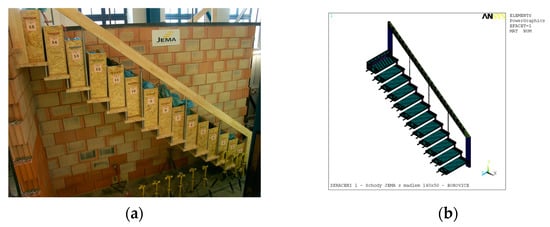
Figure 1.
(a) Prototypes of wooden staircase during static load test, full-scale experiment [7]; (b) 3D wooden staircase FEA model [7].
A combination of the abovementioned methods for verification of staircase static bearing capacity, i.e., a numerical analysis with full-scale experiments, was used by Pěnčík et al. in [7] for analysis of the behavior of prefabricated wooden staircases with one-sided suspended stairs made from Scots pine (Pinus sylvestris L.), by Lavický et al. in their analysis of a prefabricated winder wooden staircase with central stringer made from Scots pine (Pinus sylvestris L.) [13], and by Pousette in [14] for testing and modeling of the behavior of wooden stairs and stair joints. The numerically determined results in [13] showed the suitability and necessity to idealize the construction (Figure 2) in question by the numeric static model in more detail and with higher accuracy.
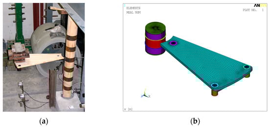
Figure 2.
(a) Prototypes of wooden step during static load test, semi-scale experiment [13]; (b) 3D wooden step FEA model [13].
According to Sachs et al. [15], apart from the staircase structure static load, it is necessary to pay attention to vibrations caused by people walking, i.e., dynamic effects on the structure. The assessment of the effect of the presence of people on dynamic behavior of steel staircases was published by Cappellini et al. in [16], where a methodology of quantification of modal parameter changes due to the presence of passive people on a narrow structure was applied. Dynamic tests can be considered as an advanced level of a structure analysis, which is preceded by a static load test, a full-scale experiment, and a numeric simulation [17,18].
In constructions, the most frequently used staircases are monolithic reinforced concrete staircases. In order to speed up the construction process and remove the wet process, prefabricated staircases [19] are currently used more often than monolithic staircases. They are made from steel, concrete, or wood. In European Union countries, the requirements for these types of staircases are defined in accordance with Eurocode 1: Actions on structures-Part 1-1: General actions - Densities, self-weight, imposed loads for buildings [20] and ETAG 008: Prefabricated Stair Kits [21].
A project of the Technological Agency of the Czech Republic TH04020263 tested the potential to use cement fiber boards (CFBs) for building constructions. CFBs have had a long history of application in civil engineering, and the most commonly used CFBs are produced by Hatschek technology [22], which is based on the principle of a machine for production of cardboard [23]. CFBs usually produced by this technology are used in the form of facade panels [24,25,26] roofing [27,28], shuttering [29,30], or interior acoustic tiles [31]; in all these cases, thin boards up to a thickness of 12 mm are used. Potential application areas for CFBs are interior staircase structures.
The Hatschek method [22] production process includes creation of so-called monoboards with thickness of up to 6 mm by layering thin cement fiber layers on an accumulation cylinder. CFBs are made by gradual layering of monoboards and subsequent compression by a hydraulic press. Applying pressure leads to water removal as well as to interconnection of monoboards into a single body. By applying the mentioned production process, it is possible to make a CFB with a final limiting thickness of up to 40 mm. However, this limiting thickness often causes spontaneous delamination of individual monoboards. Based on long-term tests [32], it was decided to use boards with the maximum thickness of 30 mm, in order to further develop the use of CFBs. Neither spontaneous delamination, nor their deformation, nor surface damage occurs with those boards during maturing.
The publication [32] claims that strength and toughness in the direction perpendicular to the fiber orientation (perpendicular to production direction, also referred to as parallel to the board mid-plane—directions x and z in Figure 3) are higher than in the case when the board is loaded perpendicular to the board mid-plane (direction y in Figure 3). In [33], microstructural anisotropy was confirmed, which is the direct cause for the mentioned macroscopic mechanic behavior. This fact appears to be beneficial for the overall load-bearing capacity of the main supporting element—the stringer. The results and course of the full-scale experiment and numeric simulation are presented by the authors in this publication, which describes the same cement fiber boards (CFBs) reinforced with cellulose fibers for creating the segment stringer staircase as those described by Nespěšný et al. in [32].
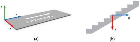
Figure 3.
(a) Cement fiber board orientation by direction of production with definition of coordinate system [x, y, z]; (b) orientation of stringer from cement fiber boards.
Interest in prefabrication in the scientific community was at its peak in the 1990s. Along with the development of new materials and technologies, prefabrication has been improved over the years [34]. The advantages of prefabricated constructions are summarized in [35], where the authors mention, in particular, increased work productivity, efficiency in quality control, reduction of construction costs, shortened period of work, and last, but not least, automation. The application of prefabricated structures is still current, which is also confirmed by the publication [36], which evaluates the life cycle (LCA) of prefabricated temporary construction in China. In the comparative LCA calculations, the authors took into account the use of prefabricated staircases and also pointed to the ecological benefit. The development of the use of globally available fiber cement board material can be considered innovative and promising for the further development of prefabricated stairs.
2. Materials and Methods
Within the study, a real staircase according to the requirements of standard ČSN 73 4130 [2] was produced and tested with the use of a full-scale experiment (in 1:1 scale). The staircase was assembled from cement fiber board segments reinforced with organic cellulose fibers. It is a group of cement fiber boards with a high cement content and lower content of the primary reinforcing fiber from cellulose, i.e., “low fiber content” [37]. The ingredient used for production of cement fiber board is cement with the main components being Portland clinker (≈84.5 wt. %, specification in Table 1), cellulose (≈8 wt. %), expanded pearlite (≈7 wt. %), and polypropylene fiber (≈0.5 wt. %). The raw materials used in production can be seen in the detailed analysis of the broken sample in Figure 4.

Table 1.
Physico-chemical composition of cement.
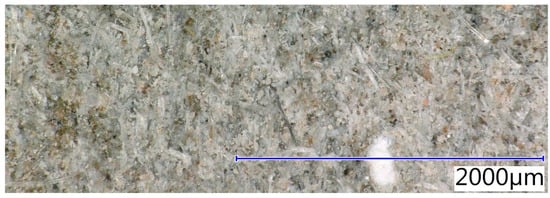
Figure 4.
Detail of used fiber cement board, tensile failure.
Regarding the use of cement fiber boards for building construction, it is often necessary to combine arrangements of material, i.e., some elements are loaded as slab elements (⊥), e.g., tread, while some structure elements are loaded as wall elements (||), e.g., stringer. Therefore, before designing and producing the staircase structure, mechanical property determination was performed, as described by Nespěšný et al. in [32], and the average values determined by four-point bending are shown in Table 2. The specific fracture energy and fracture toughness values were determined according to Karihaloo [38]. From the results of the experiment, it can be seen that the biggest difference between the parallel to board mid-plane and perpendicular to board mid-plane variants is in the strength in simple compression and simple tension.
Table 2.
Overview of experimentally determined mechanical properties of cement fiber boards with cellulose fibers [N/mm2].
2.1. Preliminary Numerical Analysis of the Staircase
The CFB material produced by the Hatschek method can be classified as a quasi-brittle material, similar to concrete. Regarding analyses of CFBs with the method of finite elements, it is possible to use several approaches of geometric modeling and material behavior modeling based on the type and purpose of the performed analysis. It is possible to use specialized programs for analyzing quasi-brittle materials, e.g., ATENA software. The analyses work with nonlinear behavior in terms of material and geometry, and the analyses may also include the effect of construction nonlinearity. When using the ATENA program, which includes specially designed algorithms for modeling behavior of a quasi-brittle material from a no damage state up to a complete failure state, based on a cohesion crack model, it is possible to use a material model SBETA [39], and its process is described in Figure 5. According to [33], CFB material can be characterized as a material with microstructural anisotropy. However, idealization of CFB behavior modeling can be used for calculations.

Figure 5.
(a) Failure criterion for the 2-axial stress state case; (b) SBETA material model with material failure in tension.
The cement fiber board’s nonlinear response under biaxial stress is explained through two parameters: the effective stress and the equivalent uniaxial strain (Figure 5). Generally, the effective stress is a primary stress. To eliminate the Poisson effect under plane stress, an equivalent uniaxial strain is used.
By assuming that the nonlinearity, which represents damage, is solely caused by the governing stress , the equivalent uniaxial strain can be defined as the strain that would be generated by the stress in a uniaxial test with a modulus linked to direction i.
The unloading process in tension and also in compression follows a straight line back to the origin, as demonstrated by points A and B in Figure 5. For this reason, the relationship between effective stress and equivalent uniaxial strain is influenced by the load history. If the equivalent uniaxial strain increment changes sign, the unloading stage changes to loading stage. The loading process follows a straight line back to point A or B, after which the loading process will continue. The maximum compression and tension stress values and are computed based on the biaxial stress state. Therefore, the equivalent uniaxial stress–strain law reflects the biaxial stress state.
When producing CFBs by the Hatschek process, the rotation of production rollers causes the reinforcing fibers to orientate along the production direction. In addition, a CFB is made by layering monoboards and their subsequent compression into a single body. This production process clearly defines the longitudinal direction z, which is identical to the dominant orientation of reinforcing fibers, or direction of production and directions x and y, respectively (Figure 3). The design of the dimensions of the stair load-bearing elements, i.e., 20 mm thick treads and 40 mm thick tread supports (from two 20 mm thick slabs) with 30 mm thick slabs, was verified by numerical analysis using the ATENA software for nonlinear analyses of structures with use of the SBETA material model mentioned above (Figure 6), taking into account the experimentally determined CFB properties listed in Table 2. The model case does not take into account the repeated loading of the structure and the occurrence of permanent deformations.
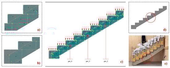
Figure 6.
(a) Detail of staircase structure during load test (upper part); (b) detail of the staircase structure during the load test (lower part); (c) model of the construction of an interior staircase made of fiber cement boards in ATENA software; (d) localization of crack initiation on the staircase structure in numerical simulation; (e) actual failure of the staircase with crack marking, actual load on the structure 9.25 kN/m2.
A quadrilateral computational mesh model with a computational side size of 10 mm was chosen as the macro element. The maximum number of iterations in one computational step was set to 80. The Newton–Raphson [39] computational method was used, in which the following set of nonlinear equations is obtained by applying the concept of step-by-step analysis:
where is the vector of total applied joint loads, is the vector of internal joint forces, is the deformation increment due to loading increment, p are the deformations of the structure prior to load increment, is the stiffness matrix, relating loading increments to deformation increments.
The portion on the right side of Equation (2) denotes the forces that exist outside of equilibrium during the load increment. This means it represents the overall load level after the load increment is applied, minus the internal forces that were present at the end of the previous load step. Typically, the stiffness matrix is dependent on strain, meaning it is a function of p. However, it is generally ignored during the load increment to preserve linearity. Instead, the stiffness matrix is calculated based on the value of p related to the level before the load increment.
Three measuring points were selected on the structure to record the vertical displacements (referred to as pot_2, pot_3, and pot_4 in the experiment as shown in Figure 7.
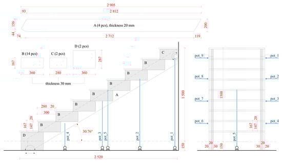
Figure 7.
Construction scheme of segment stringer staircase for staircase structure (A is stringer part, B–D is step support)—top, staircase cross section—left, front view—right.
The loading of the structure in the numerical simulation was carried out in steps as planned in the experimental load test. The arrangement of the load test was identical to the boundary conditions in the proposed experiment. Possible horizontal displacement at the base of the staircase was considered, while horizontal and vertical displacements at the upper part of the structure were avoided for numerical simulation purposes (Figure 6). In numerical simulation at a load of intensity 3.0 kN/m2, there was no loss of stability. At this load, the vertical displacement at pot_3 was 1.819 mm. The collapse of the structure occurred at a load of intensity of 7.35 kN/m2. Before the loss of stability, the vertical displacement was 4.096 mm.
2.2. Production and Assembly of One-Arm Stringer Staircase
The staircase was designed as segmented, stringer, straight, with 9 steps, with construction height of 1500 mm, with staircase arm width of 900 mm, and staircase arm inclination of 30.76°. With its dimensions, the designed staircase corresponded with the common U-shaped stringer staircase with 2 outside stringers in family houses; the design was based on staircase equation 2h + b = ls, where h is the height of a staircase step in mm, b is the width of a staircase step in mm, and ls is the length of an average human step in mm. In the case of the designed staircase, the considered average human step length was assumed to be equal to 630 mm. For material savings, the optimized cutting plan in Figure 4 was designed in such way that the amount of waste during the segment cutting was minimized. Individual staircase segments were manually cut by a plunge saw from large cement fiber boards reinforced by organic cellulose fibers with dimensions of 3000 × 1200 mm and thickness of 20 mm and 30 mm.
Segments A–D in Figure 7 were used to build the staircase. The staircase was assembled systematically as shown in Figure 8a–g. The first step (a) included clamping of two segments (A) from which the stringer was made using F-shaped heavy duty bar clamps. Subsequently, (b) measuring and drilling of holes for screws in segments (B, C, and D) and (c) measuring and drilling of holes for screws in stringers (A) were carried out. In the next step, (d) step supports (B, C, and D) were fitted by screws to stringers (A). In the last step, (e) and (f) holes were predrilled for fitting steps (E) to step supports (B, C, and D). All joints in the staircase structure were fitted by screws. Concrete HILTI HUS3-C 6 and HILTI HUS3-P 6 screws were used for fitting connections. For stringer segments (A) and step supports (B, C, and D), flat head heavy duty galvanized screws (min. 5 µm) with length of 60 mm and diameter of 6 mm made from carbon steel were used. For screw joints of steps, screws from the same material with a different length of 40 mm with countersunk head were used. Photo documentation of the whole production procedure is shown in Figure 8a–f. The assembled staircase was then put into a designed and new-build testing polygon for testing interior staircases made from CLT panels Figure 8g and was subjected to load tests.
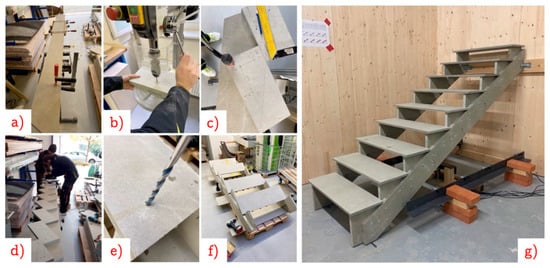
Figure 8.
Assembly of interior staircase made from cement fiber boards. (a) Clamping of two segments of stringer; (b) measuring and drilling of holes for screws in step supports; (c) measuring and drilling of holes for screws in stringers; (d) screwing step supports; (e) drilling of holes for screws in tread; (f) gradual screwing of tread; (g) installation of the staircase structure in the test polygon.
2.3. Preparation and Procedure of Static Load Tests
Experimental testing was performed to verify staircase bearing capacity under loading defined by standard Eurocode 1: Actions on structures - Part 1-1: General actions - Densities, self-weight, imposed loads for buildings [20]. Regarding statics, the load test was performed under the least favorable conditions. The staircase was designed as a simply supported beam made by 2 stringers with fixed joints in the upper part, where the joints were made with 4 steel galvanized L-bars with a groove of 65 × 90/90 with threaded rods with diameter of 10 mm running through steps, and the movable support was simulated by a steel rod with diameter of 10 mm, as shown in Figure 9. Two eight-channel switchboards were used for continual recording of vertical displacements of the staircase structure Uy,i [mm] in time during the experimental tests, and the recording speed during the load test was 2 Hz. Vertical displacement Uy,i of nine measuring points (pot_1 to pot_9) was monitored by nine potentiometric motion sensors. During the staircase loading, the values of vertical displacement Uy,I in 1/3, in 1/2, and in 2/3 of the stringer span were recorded (Figure 7). An individual sensor was placed in the middle of the fifth step (Figure 9).
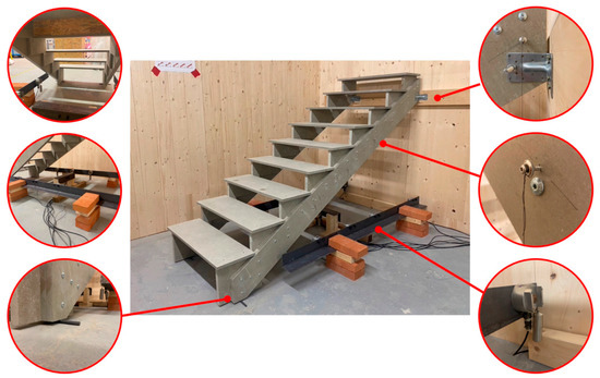
Figure 9.
Preparation of experiment, interior staircase structure before loading.
Staircase loading was applied by loading boxes made from OSB boards without bottoms with approximate weight mb = 10.5 kg. The reason for using boxes without bottoms was for truer modeling of the effect of continuous loading on a staircase step. Loading bags, whose weight corresponded with the loading for individual loading phases mb,2 = 35 kg, mb,3 = 30 kg, mb,4 = 22.68 kg, mb,5 = 15.12 kg, were placed in loading boxes. All loading bags were filled with pebbles of fraction 2/4 mm. The order of placing loading boxes No. 1 to No. 9 was determined on the basis of an optimized calculation. The aim was to place loading boxes and loading bags in such an order that the course of the bending moment by the applied loading became as similar to the course of the bending moment by the continuous uniform loading as possible. Therefore, loading of individual staircase steps was performed in the order of 7th, 2nd, 6th, 3rd, 8th, 1st, 5th, 4th, 9th, and load removal of the structure was performed in the reverse order. The order of loading and load removal is shown in Figure 7.
The static load test was divided into two phases—loading and load removal (Figure 10). The loading and load removal cycle was performed three times. A break of 15 minutes occurred between individual phases and between individual loading steps, i.e., 1.0 × Vk, 1.3 × Vk, and 1.5 × Vk, where Vk is surface characteristic value of vertical uniform surface load for stairs according to 3.0 kN/m2 defined according to [20], with respect to the national annex. The break was carried out in order to stabilize the staircase structure and to stabilize vertical displacements Uy, and to monitor the structure relaxation over time. The staircase was loaded in two loading cycles that included monitoring of the structure vertical displacement Uy and subsequently the load was applied up to the structure collapse. The first and second loading were performed according to the scheme: Gk → 1.0 × Vk → 1.3 × Vk → 1.5 × Vk → 1.3 × Vk → 1.0 × Vk → Gk, where Gk is the characteristic weight of the structure. In the last measurement, the structure was loaded up to reaching the ultimate rupture limit according to the scheme: Gk → 1.0 × Vk → 1.3 × Vk → 1.5 × Vk → gradual increase in loading in multiples of 0.2 × Vk up to the loss of stability, when the structure collapsed. An overview of loading of individual staircase steps and an overview of loading of the whole structure are described in Table 3.
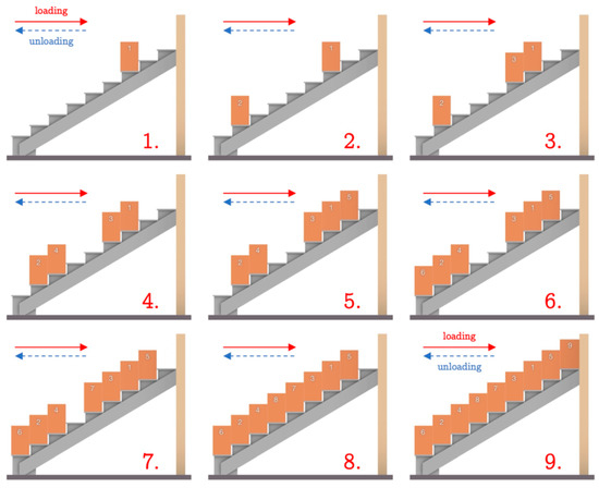
Figure 10.
Order of placing/removing of loading boxes. Number 1. to 9. indicates the sequence of loading or unloading of the structure.
Table 3.
Loading of individual (1st to 9th) staircase steps [kg] summed according to loading steps [kg/staircase step].
3. Results and Discussion
The staircase under applied loading of Gk up to 1.5 × Vk, defined according to standard ČSN EN 1991-1-1 [20], in the first and the second load test did not show any defects in the form of cracks, delamination, or breakage in places of screw joints. The maximum vertical displacement was reached at loading of 1.5 × Vk in the middle of staircase step No. 5, where the vertical displacement of Uy,pot_5 = 6.62 mm was recorded. In the first load test, the highest permanent deformation occurred at measuring point pot_9 (sinking of the left support, deformation of steel L-bars which were used for mounting of the staircase to the testing polygon), where Uy,9 = 3.13 mm. During the first load test, the ultimate bend limit was not exceeded, it was converted to a vertical displacement and determined according to [7,21], with the size of Uy,lim = 17.48 mm. The graph in Figure 11 of the whole first load test of the stringer staircase (A) shows significant relaxation of the stringer in the range of E–F, i.e., at loading of 1.5 × Vk. In contrast, during the break in loading in the range of A–B, i.e., at loading of 1.0 × Vk, the relaxation is negligible. The behavior of the structure shows that, with increasing loading, higher relaxation of the structure and a more pronounced increase in vertical displacement occur. A detailed profile of the first loading of the structure from Gk to a load of 1.0 × V is shown in Figure 12. The gradual unloading of the structure after the first loading is shown in detail in Figure 13.
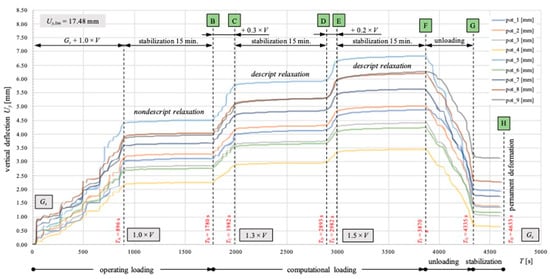
Figure 11.
Course of static load test of interior staircase, whole range of first measurement.
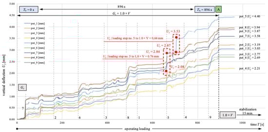
Figure 12.
Course of static load test, first measurement, detail of loading Gk to A.
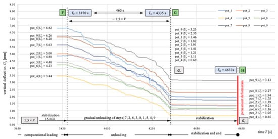
Figure 13.
Course of static load test, first measurement, detail of load removal F to Gk.
During the second load test Figure 14, the highest permanent deformation at measuring point pot_9 (sinking of the right support) occurred, where Uy,9 = 0.59 mm. The deformation at the second loading was significantly lower than at the first loading. This phenomenon was probably caused by the effect of the first loading on the structure under which the whole structure got into shape, potential production inaccuracies closed up, and the connecting elements were activated. During the second load test, the ultimate vertical displacement was not exceeded, Uy,lim = 17.48 mm. The graph in Figure 11 of the whole second load test of the stringer staircase (A) shows significant relaxation of the stringer in the range of E–F, i.e., at loading of 1.5 × Vk. In contrast, during the break in loading in the range A–B, i.e., at loading of 1.0 × Vk, the relaxation is negligible—similarly to the first load test. A detailed profile of the second loading of the structure from Gk to a load of 1.0 × V is shown in Figure 15. The gradual unloading of the structure after the second loading is shown in detail in Figure 16.
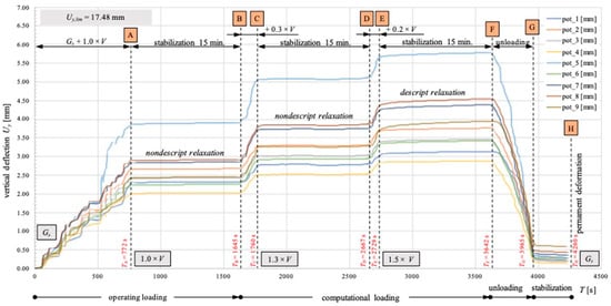
Figure 14.
Course of static load test of interior staircase, whole range of second measurement.
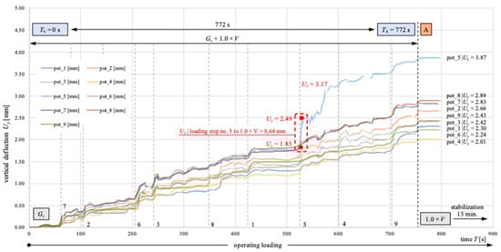
Figure 15.
Course of static load test, second measurement, detail of loading Gk to A.
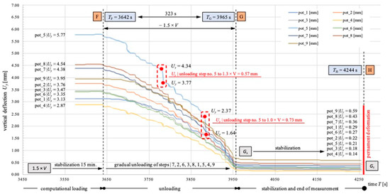
Figure 16.
Course of static load test, second measurement, detail of load removal F to Gk.
4. Conclusions
Based on the assessment of experimental loading of a stringer interior staircase made from cement fiber boards reinforced with cellulose fibers, the following summary was produced:
- According to ETAG 008 [21], a single load test for a staircase structure should be sufficient. Based on the performed experiments, we found that recurring loading leads to a significant decrease in permanent deformations (Table 4). Large permanent deformations during the first loading are partially caused by production inaccuracies closing up and activation of connecting elements. The values of permanent deformations shown in Table 4 are comparable for a wooden staircase and a cement fiber board staircase in relation to the constructional arrangement. The presented results in this publication show that permanent deformation value was lower by 2.54 mm after the second measurement. Therefore, a suitable recommendation is to first activate the structure by partial loading, and then to load it with the prescribed loading. The results of only a single load test cannot be considered relevant.
Table 4. Comparison of maximum permanent deformations on a staircase structure after experimental loading.
- After meeting the standard requirements, the tested staircase was gradually loaded up to its collapse. The collapse occurred under a total applied load of 2100.6 kg (Figure 17); this value corresponds with a surface loading of 9.26 kN/m2 (without the self-weight of the structure itself). The surface value of load was exceeded by 131.5%.
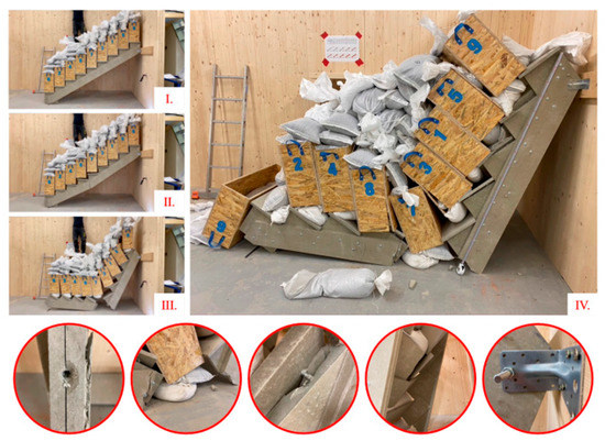 Figure 17. Failed interior staircase structure made from cement fiber boards under loading of 9.26 kN/m2, detailed photo documentation of failed structure. Where (I) is the structure of the staircase before the crack appeared, (II) the first appearance of a crack on the structure, (III) broken staircase structure, (IV) detailed view of the broken structure.
 - The used method of loading was considered useful for testing interior staircases. The research of standards and regulations found that loading breaks are not required. Based on the experimental assessment, we found that breaks are useful for the structure relaxation, and it is recommended to choose the break duration so that vertical displacements stabilize.
- Based on the experimental measurement, a sufficient duration of the loading break is considered an interval when the change in recorded vertical displacements in the next step will not be higher than 0.5%.
- Numerical verification of a cement fiber board staircase structure failure, while using a material SBETA model in ATENA software, differs by 1.91 kN/m2 from the real loaded model. The difference between the vertical displacements for the numerical simulation and the second real load test in the middle of the staircase (pot_3) at a load of 3.0 kN/m2 was 0.6 mm. The vertical displacement before the first crack in the numerical simulation in the middle of the staircase was 4.096 mm, which corresponds to the vertical displacement at the end of the second real load test. The crack development in the numerical model is comparable to the real load test. The difference between the numerical simulation and the real experiment can be caused by material imperfection and imperfect arrangement of the load test. For an optimal design of staircase construction, it is necessary to continue working on the development of the material model and material specifications.
Author Contributions
Conceptualization, O.N. and J.P.; methodology, J.P.; validation, J.P., O.N. and D.B.; formal analysis, J.V. and M.N.; writing—original draft preparation, O.N., J.P. and V.V.; supervision, J.P.; project administration, D.B., O.N. and M.N.; funding, M.N. All authors have read and agreed to the published version of the manuscript.
Funding
The research was produced with financial support for specific university research at Brno University of Technology, grant number FAST-J-22-7907, and specific university research at Brno University of Technology, grant number FAST-S-22-8000.
Data Availability Statement
The data presented in this study are available on request from the corresponding author. The data are not publicly available due to ethical reasons.
Acknowledgments
The preparation and implementation of the experimental loading were carried out in the test polygon at the Institute of Building Structures, Faculty of Civil Engineering, University of Technology in Brno.
Conflicts of Interest
The authors confirm that there is no known conflict of interest associated with this paper, and there has been no significant financial support for this work that could have influenced its outcome.
References
- Zamirian, P. Stair and Staircases: Stair Design, 1st ed.; GlobeEdith: Chisinau, Moldova, 2021; ISBN 978-620-0-62524-3. [Google Scholar]
- ČSN 73 4130; Schodiště a Šikmé Rampy–Základní Požadavky. Office for Technical Standardization, Metrology and State Testing: Prague, Czech Republic, 2010.
- DIN 18065:2015-03; Stairs in Buildings–Terminology, Measuring Rules, Main Dimensions. Normenausschuss Bauwesen (NABau): Berlin, Germany, 2015.
- BS 5395-1; Stairs–Code of Practice for The Design of Stairs with Straight Flights And Winders. British Standards Institution (BSI): London, UK, 2010.
- Vesela, L. Staircase–Dimensions of Stair Steps and their Deviations of Geometrical Accuracy. IOP Conf. Ser. Mater. Sci. Eng. 2019, 471, 022012. [Google Scholar] [CrossRef]
- Trenz, J.; Zlatuška, K.; Nečas, R. Experimental model of plan curved footbridge supported by arch. IOP Conf. Ser. Mater. Sci. Eng. 2020, 960, 042070. [Google Scholar] [CrossRef]
- Pěnčík, J.; Lavický, M.; Kral, P.; Havířová, Z. Analysis of Behaviour of Prefabricated Staircases with One-Sided Suspended Stairs. Drv. Ind. 2015, 66, 147–156. [Google Scholar] [CrossRef]
- Fleming, P.H.; Ramage, M.H. Full-scale construction and testing of stress-laminated columns made with low-grade wood. Constr. Build. Mater. 2020, 230, 116952. [Google Scholar] [CrossRef]
- Zuo, Z.; Gong, J.; Huang, Y.; Zhan, Y.; Gong, M.; Zhang, L. Experimental research on transition from scale 3D printing to full-size printing in construction. Constr. Build. Mater. 2019, 208, 350–360. [Google Scholar] [CrossRef]
- Li, B.; Fang, H.; He, H.; Yang, K.; Chen, C.; Wang, F. Numerical simulation and full-scale test on dynamic response of corroded concrete pipelines under Multi-field coupling. Constr. Build. Mater. 2019, 200, 368–386. [Google Scholar] [CrossRef]
- Paschalis, S.A.; Lampropoulos, A.P.; Tsioulou, O. Experimental and numerical study of the performance of ultra high performance fiber reinforced concrete for the flexural strengthening of full scale reinforced concrete members. Constr. Build. Mater. 2018, 186, 351–366. [Google Scholar] [CrossRef]
- Furtado, A.; Arêde, A.; Rodrigues, H.; Varum, H. The role of the openings in the out-of-plane behaviour of masonry infill walls. Eng. Struct. 2021, 244, 112793. [Google Scholar] [CrossRef]
- Lavický, M.; Pěnčík, J.; Dohnal, J.; Bečkovský, D.; Bečkovská, T. Static numeric and experimental analysis of prefabricated winder wooden staircase with central stringer made from Scots pine (Pinus sylvestris L.). J. Wood Sci. 2016, 61, 553–564. [Google Scholar]
- Pousette, A. Testing and modeling of the behavior of wooden stairs and stair joints. J. Wood Sci. 2006, 52, 358–362. [Google Scholar] [CrossRef]
- Sachse, R.; Pavic, A.; Reynolds, P. Human-Structure Dynamic Interaction in Civil Engineering Dynamics: A Literature Review. Shock Vib. Dig. 2003, 35, 3–18. [Google Scholar] [CrossRef]
- Cappellini, A.; Manzoni, S.; Vanali, M.; Cigada, A. Evaluation of the dynamic behaviour of steel staircases damped by the presence of people. Eng. Struct. 2016, 115, 165–178. [Google Scholar] [CrossRef]
- Busca, G.; Cappellini, A.; Manzoni, S.; Tarabini, M.; Vanali, M. Quantification of changes in modal parameters due to the presence of passive people on a slender structure. J. Sound Vib. 2014, 333, 5641–5652. [Google Scholar] [CrossRef]
- Pěnčík, J. The Material Non-linear Analysis of Concrete Plane Frame Structures. In Proceedings of the 3rd PhD Symposium: Section Construction and Structural Mechanics, Brno, Czech Republic, February 2001; pp. 89–92. [Google Scholar]
- Li, X.-J.; Xie, W.-J.; Jim, C.Y.; Feng, F. Holistic LCA evaluation of the carbon footprint of prefabricated concrete stairs. J. Clean. Prod. 2021, 329, 129621. [Google Scholar] [CrossRef]
- ČSN EN 1991-1-1; Eurocode 1: Actions on Structures—Part 1-1: General Actions—Densities, Self-Weight, Imposed Loads for Buildings. The European Standard; Český Normalizační Institut: Prague, Czech Republic, 2004.
- ETAG 008; Prefabricated Stair Kits. 1st ed. European Organization for Technical Approvals: Brussels, Belgium, 2002.
- Hatschek, L. Machine and Process for Making Asbestos Cement Pipes. Austria Patent AT132270B, 10 March 1933. Available online: https://patents.google.com/patent/AT132270B/de?assignee=Eternit+Werke+Hatschek+L&oq=Eternit+Werke+Hatschek+L&sort=old (accessed on 22 February 2023).
- Ranachowski, Z.; Schabowicz, K. The Fabrication, Testing and Application of Fibre Cement Boards, 1st ed.; Cambridge Scholars Publishing: Newcastle upon Tyne, UK, 2018; ISBN 978-1-5275-0576-6. [Google Scholar]
- Schabowicz, K.; Sulik, P.; Zawiślak, Ł. Identification of the Destruction Model of Ventilated Facade under the Influence of Fire. Materials 2020, 13, 2387. [Google Scholar] [CrossRef]
- Mukhametrakhimov, R.; Galautdinov, A.; Lukmanova, L.; Khuzin, A.; Lamberov, A.; Egorova, S.; Murgul, V. Modified fiber cement panels for civil construction. MATEC Web Conf. 2017, 106, 04005. [Google Scholar] [CrossRef]
- Gorzelańczyk, T.; Schabowicz, K.; Szymków, M. Application of the Acoustic Emission Method and Artificial Neural Networks to Assess the Damaging Effect of High Temperature on the Structure of Fibre-Cement Boards. Materials 2022, 15, 6460. [Google Scholar] [CrossRef]
- Dias, C.M.R.; Campello, E.M.B.; Savastano, H.; John, V.M. Exploratory pre-industrial test linking FGM and Hatschek technologies for the manufacture of asbestos-free corrugated cementitious roof sheets. Constr. Build. Mater. 2018, 190, 975–984. [Google Scholar] [CrossRef]
- Michels, C.; Güths, S.; Marinoski, D.L.; Lamberts, R. Thermal performance and thermal resistance of fibre cement roof tiles: Experimental study. Energy Build. 2021, 231, 110569. [Google Scholar] [CrossRef]
- Kildashti, K.; Samali, B.; Malik, A.; Alamdari, M.M. Computational simulation of eccentrically loaded reinforced concrete walls formed with modular thin-walled permanent formwork system. J. Build. Eng. 2021, 36, 102131. [Google Scholar] [CrossRef]
- Kildashti, K.; Samali, B.; Malik, A. Experimental and numerical studies on the comparison between stay-in-place- and conventionally-formed reinforced concrete columns under concentric loading. Constr. Build. Mater. 2020, 258, 119631. [Google Scholar] [CrossRef]
- Jun, D.; Nespesny, O.; Pencik, J.; Fisarova, Z.; Rubina, A. Optimized method for Helmholtz resonator design formed by perforated boards. Appl. Acoust. 2021, 184, 108341. [Google Scholar] [CrossRef]
- Nespěšný, O.; Pěnčík, J.; Bečkovský, D.; Vystrčil, J.; Šuhajda, K. Determination of material and elasticity constants of cement fibre boards to extend field of application. Constr. Build. Mater. 2021, 306, 124821. [Google Scholar] [CrossRef]
- Gorzelańczyk, T.; Pachnicz, M.; Różański, A.; Schabowicz, K. Identification of microstructural anisotropy of cellulose cement boards by means of nanoindentation. Constr. Build. Mater. 2020, 257, 119515. [Google Scholar] [CrossRef]
- Zhong, R.Y.; Peng, Y.; Xue, F.; Fang, J.; Zou, W.; Luo, H.; Thomas Ng, S.; Lu, W.; Shen, G.Q.P.; Huang, G.Q. Prefabricated construction enabled by the Internet-of-Things. Autom. Constr. 2017, 76, 59–70. [Google Scholar] [CrossRef]
- Rocha, P.F.; Ferreira, N.O.; Pimenta, F.; Pereira, N.B. Impacts of Prefabrication in the Building Construction Industry. Encyclopedia 2023, 3, 28–45. [Google Scholar] [CrossRef]
- Tian, Y.; Spatari, S. Environmental life cycle evaluation of prefabricated residential construction in China. J. Build. Eng. 2022, 57, 104776. [Google Scholar] [CrossRef]
- Balgaru, P.N.; Shah, S.P. Fiber Reinforced Cement Composites, 1st ed.; McGraw-Hill: New York, NY, USA, 1992; ISBN 0070564000. [Google Scholar]
- Karihaloo, B.L. Fracture Mechanics and Structural Concrete; Longman Scientific & Technical: Harlow, UK, 1995; ISBN 0-582-21582-X. [Google Scholar]
- Červenka, V.; Jendele, L.; Červenka, J. ATENA Program Documentation–Part 1: Theory. Available online: https://www.cervenka.cz/assets/files/atena-pdf/ATENA_Theory.pdf (accessed on 22 February 2023).


Disclaimer/Publisher’s Note: The statements, opinions and data contained in all publications are solely those of the individual author(s) and contributor(s) and not of MDPI and/or the editor(s). MDPI and/or the editor(s) disclaim responsibility for any injury to people or property resulting from any ideas, methods, instructions or products referred to in the content. |
© 2023 by the authors. Licensee MDPI, Basel, Switzerland. This article is an open access article distributed under the terms and conditions of the Creative Commons Attribution (CC BY) license (https://creativecommons.org/licenses/by/4.0/).