1. Introduction
The South-to-North Water Diversion Project is a world-renowned mega cross-basin water diversion project. In terms of spatial distribution, China’s water resources are mostly concentrated in the south, forming a situation of more water resources in the south and less water resources in the north. The extremely unbalanced water resources have become an important factor restricting the economic development of the northern region and even the whole country. The South-to-North Water Diversion project has alleviated the scarcity of water resources in northern China, especially in the Huang-Huai-hai Plain, and realized the strategic adjustment of and optimized the allocation of water resources in China. In order to alleviate the resource water shortage in Beijing, Tianjin, and north China, the Middle Route of the South-to-North Water Diversion Project starts from Taocha in the Danjiangkou Reservoir, passes through the Henan and Hebei provinces, and ends in Beijing and Tianjin, with a total length of 1432 km and an annual water transfer of about 9.5 billion cubic meters. It mainly supplies water to cities along the way, taking into account agriculture and ecology, benefiting 24 large and medium-sized cities and over 130 counties along the water-receiving route, directly benefiting a population of over 85 million. It mainly supplies water to cities along the way, taking into account agriculture and ecology. With high terrain in the south and low in the north, China enjoys excellent conditions for artesian water transfer. As of 30 March 2023, the Middle Route of South-to-North Water Diversion Project had transferred 55 billion cubic meters of water in total, and the water supply continued to increase rapidly. The South-to-North Water Diversion project mainly uses open channels and partially uses underground pipelines, and the concrete lining of the channel plays a key role in the South-to-North Water Diversion Project, but in the course of service, part of the concrete lining has cracked. This damage threatens the safety and water quality of the channel structure. To prevent water pollution and ensure the continued safe operation of the Project, the concrete lining must be repaired. However, the requirements of the South-to-North Water Diversion Project regarding water quality and the uninterrupted operation of the Project increase the difficulty of such repair. Therefore, it is critical to study and propose a repair methodology for concrete linings that addresses these requirements in the South-to-North Water Diversion Channel.
In recent years, scholars have researched the causes of cracks in concrete linings and proposed various preventive measures. Li et al. [
1] built a finite element model of the channel to simulate the stress field of concrete lining under the combined action of temperature, stress, and water load. The results show that the stress value of slope foot and bottom lining is larger than that of other parts. Li et al. [
2] established a finite element model to analyze the temperature characteristics of the canal lining structure under the action of heat–wet coupling, and compared the traditional lining structure with the lining structure designed to prevent frost heaving. Earthquakes are natural phenomena that have the potential to cause extensive damage to buildings, infrastructure, and various structures [
3,
4]. Dong et al. [
5], based on the Zhanghe River floodplain segment of Middle route of the South-to-North Water Diversion Project, obtained the dynamic parameters of the rock body through on-site and indoor experiments. Establish a finite element model of geotechnical engineering, they input the actual seismic waves recorded at the Handan Station near the site to conduct a dynamic numerical analysis on the characteristics of seismic liquefaction and the channel deformation and failure of the channel foundation sand soil. Zhang et al. [
6] noted that concrete linings can crack due to concrete shrinkage, while Li et al. [
7] suggested preventive measures based on various causes of cracking. Wang et al. [
8] concluded that incorporating polyethylene fibers and fly ash could improve the cracking resistance of cementitious composites.
Non-dispersible underwater concrete (NUC) is one of the most widely used materials in underwater engineering construction, and there have been numerous in-depth studies on NUC. Wongprachum et al. [
9] increased the resistance of an underwater cement mortar to sulfate attack by adding various fibers. Ali et al. [
10] studied the effectiveness of various viscosity-modifying admixtures (VMAs) to prevent washout in underwater concrete mixes and concluded that using natural polysaccharides and superabsorbent polymer could produce high-performance NUC. Wang et al. [
11] used X-ray diffraction (XRD), mercury intrusion porosimetry (MIP), and scanning electron microscopy (SEM) to identify the crystalline composition and microstructure characteristics of modified NUCs. The results found that adding nano-silica (nano-SiO
2) or nano-metakaolin significantly increased the compressive strength of the NUC samples.
Researchers have also studied the bond strength of underwater concrete. Horszczaruk et al. [
12] conducted a complex investigation into the effect of hydrostatic pressure on the bond strength of underwater concrete to a concrete substrate. The experimental results showed that sandblasting was the most effective method for the surface treatment of the substrate prior to the placement of the underwater repair concrete. Assaad et al. [
13] conducted a comprehensive study on the effect of styrene-butadiene rubber (SBR) latex admixture on the washout loss and bond strength of underwater concrete designated for repair applications. Brzozowski et al. [
14] used a special chamber to place and cure the repair concrete on the concrete substrate under the water and analyzed the influence of surface preparation on the adhesion of the repair concrete under hydrostatic pressure. Wang et al. [
15] studied the addition of three types of nanomaterials (nano-SiO
2, nano-metakaolin, and nano-aluminum oxide) into NUC to improve the strength of the interfacial transition zone (ITZ); the results indicated that the nano-SiO
2 and nano-metakaolin could significantly increase the ITZ bond strength.
A number of researchers have also investigated alternative repair methods. Kim et al. [
16] developed efficient underwater-hardening epoxy resins for the repair and reinforcement of concrete structures under wet conditions. The material properties of the developed water epoxy resins were verified through various performance evaluation experiments. Jia et al. [
17,
18] proposed the use of the microbial-induced generation of carbonate crystals as a technique to achieve self-repairing concrete. Ma et al. [
19,
20] studied the application of cementitious osmotic crystalline waterproofing coatings, cementitious flexible waterproofing coatings, and LW water-soluble polyurethane grouting material for crack repair.
Previous studies have shown that the causes of cracking in water conveyance channel linings are complex and challenging to repair. The existing repair methods are only suitable to be carried out on land, while underwater repair methods do not consider the effect of concrete pollution on the water quality. For the continued operation of the South-to-North Water Diversion Project, it is necessary to carry out underwater concrete repairs while retaining an uninterrupted water supply and without affecting the water quality. Existing methods dealing with cracks find it hard to meet long-term, frequent changes. The repair measures of the lining painted with polyacrylate latex-modified cement paste need to meet the water cut-off conditions and can not be repaired directly under water, which brings about great difficulties for construction and hinders the normal use of the South-to-North Water Diversion Project. The cost of replacing the lining is too high and is not suitable for repairing lining with fewer penetrating cracks, and the impact of this scheme on water quality during the lining removal process is unclear. Therefore, it is urgent to find concrete for the repair of cracks in underwater lining. The whole repair process should meet the need to maintain water supply throughout the repair process and the requirement of ensuring that repair materials do not negatively affect the water quality. To solve this problem, we proposed the use of NUC for underwater lining repair. Compared to previous repair methods, the repair process is simpler, there is no need to keep the lining dry, and can repairs can be carried out directly underwater using NUC. However, most of the previous studies have focused on mechanical properties and lacked detailed studies on the effects of NUC on water quality. This study determined the optimal mixing ratio of NUC while studying the impact of such underwater concrete on the water quality of the South-to-North Water Diversion. This research aims to provide a basis for the ongoing repairs to the concrete lining in the South-to-North Water Diversion Project.
2. Concrete Lined Channels of the South-to-North Water Diversion Project
A typical channel cross-section of the South-to-North Water Diversion in the vicinity of Yuzhou is shown in
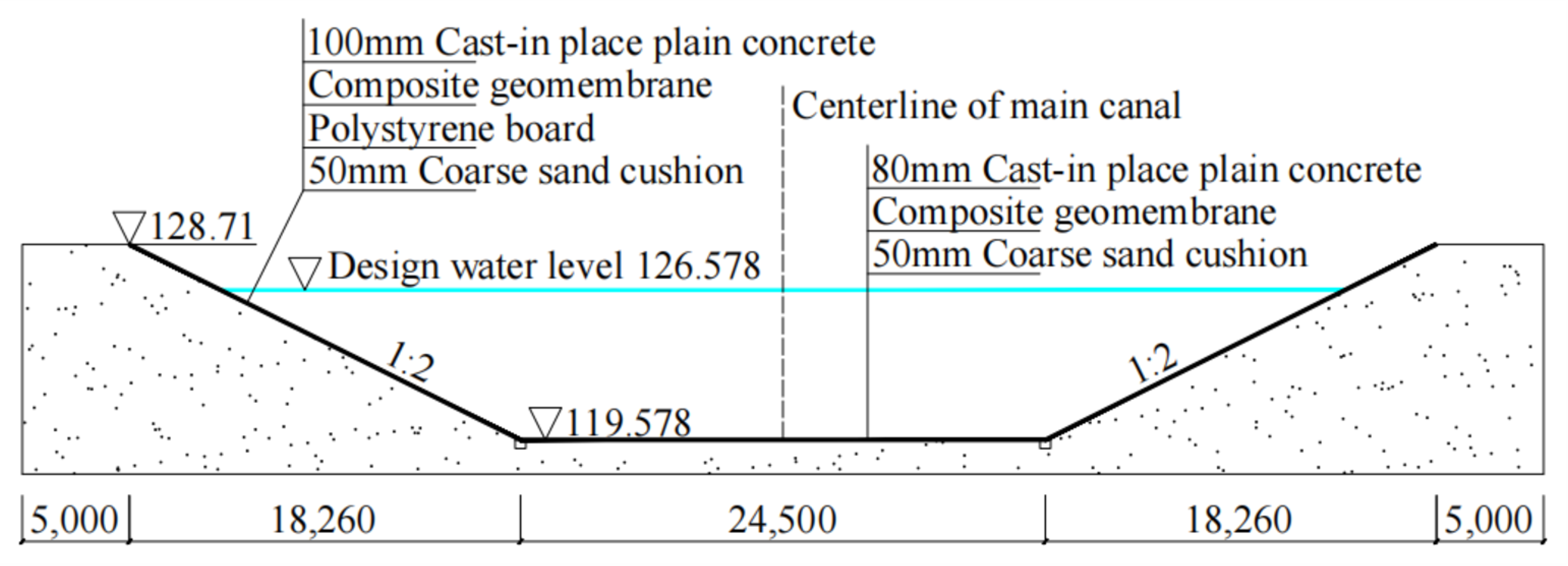
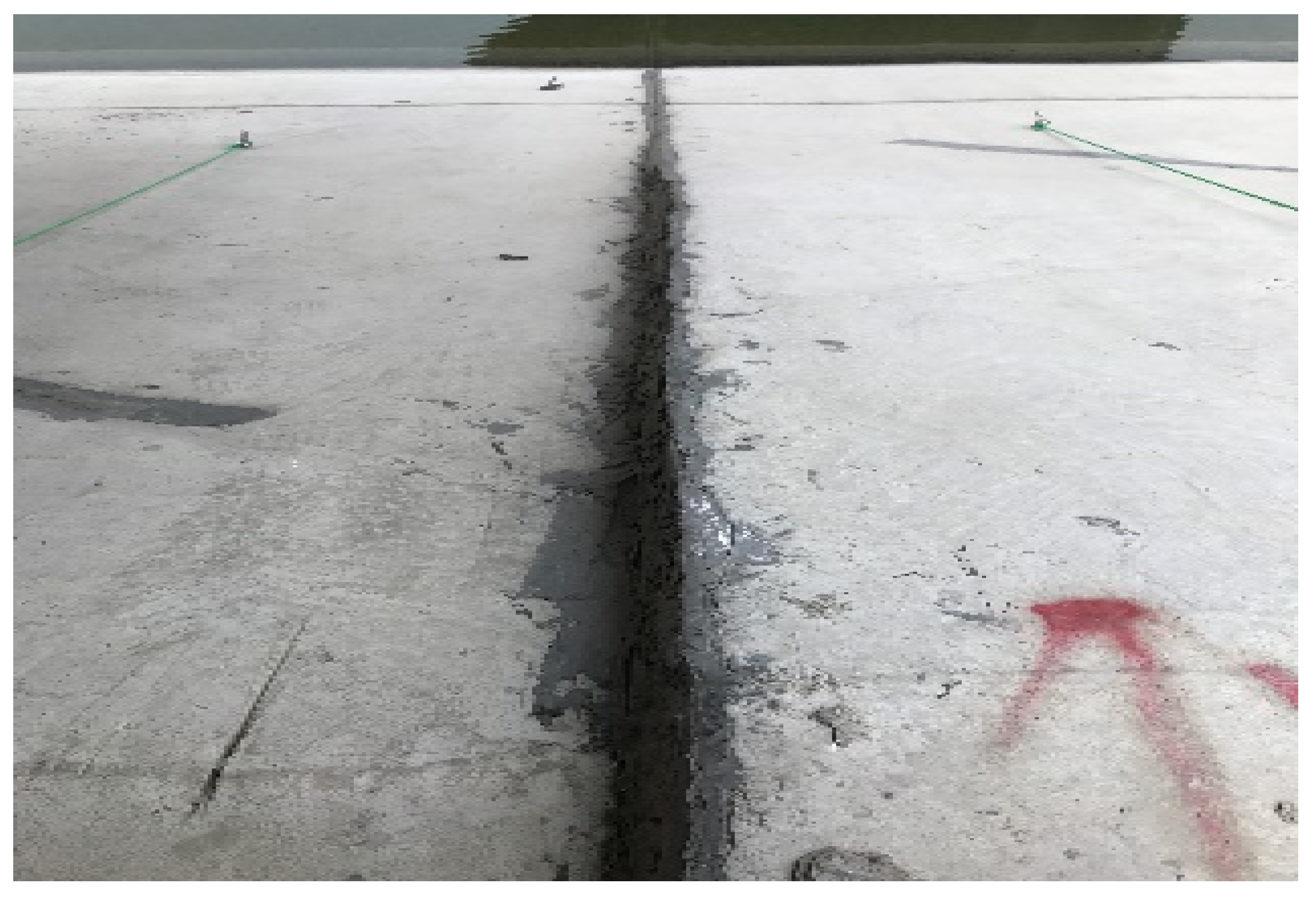
Figure 1. On the sloped sides, the concrete lining consists of 100 mm thick cast-in-place concrete slab panels; the central panel is 4 × 4 m, while the upper and lower sections are 4.30 × 4 m. The lining panels at the channel’s base are 80 mm thick, with 4 × 4 m central panels and 4.25 × 4 m side panels. Separation joints are provided between each panel. The water depth from the base to the design water level is approximately 7 m. The composite geomembrane below the concrete panels acts as an impermeable layer and is underlain with 50 mm coarse sand bedding, which, in turn, overlays the clayey soil. During the operation of the project, due to factors such as the uneven soil quality of the foundation, changes in groundwater level, or incomplete backfill, soil settlement is prone to occurring, leading to lining cracks. At the end of 2017, cracks appeared in several underwater and exposed linings in this section. In addition, there was evidence of differential settlements between the panels, with the maximum differential settlement being measured as 30 mm, as shown in
Figure 2. The cracks and settlement were monitored on-site over six months. At the end of that period, it was established that the foundation soil settlement had stabilized, and the settlement cracks were no longer developing. According to the observation results, the settlement amount of the foundation is less than 1 mm per month, and the uneven settlement meets the settlement stability requirements of the Chinese standard JGJ8-2016 [
21]. Therefore, this was deemed as an appropriate time to address the underwater repair of the cracks.
Previously, there was a crack repair program for channel lining in the Nanyang section of the Middle Route of the South-to-North Water Diversion Project [
22]. For the lining with a large number of non-penetrating cracks, the whole lining plate was painted with polyacrylate latex-modified cement paste, then the excess paste was wiped clean with a wet towel, and the cracks were carefully covered with a small piece of curing film to keep them moisturized. This program needs to be carried out when the lining is dry, and for underwater lining, the construction procedure is complicated and the repairs encounter difficulties. The lining cracks in the Cixian section of the Middle Route of the South to North Water Diversion Project have also been repaired. The construction procedures of this repair program [
23] include: pile formwork cofferdam construction, water operation platform construction, the removal of damaged lining plates, the lifting and protection of damaged lining plates, foundation treatment, the installation of reinforced concrete precast plates, and the removal and cleaning of pile formwork cofferdams. However, the impact of this scheme on water quality during the lining removal process is unclear, and during the assembly and repair of reinforced concrete precast slabs, it is necessary to resist groundwater uplift pressure, which may lead to further damage. If the original lining can be repaired underwater without dismantling, it will thoroughly reduce the difficulty of construction and ensure construction safety.
3. Optimization of NUC Mix Ratio
NUC is made by adding an anti-dispersant (also known as a flocculant) to concrete to prevent the dispersal or segregation of the concrete through water flow when the concrete is poured underwater. NUC possesses a good workability and self-compacting, self-leveling, and anti-dispersive properties [
24,
25]. Studies have been conducted on the effect of different admixtures on the dispersion resistance, durability, and other properties of NUC [
26,
27]. Existing research has primarily focused on the mechanical properties of NUC and its constituents, with minimal research on the underwater crack repair methodology for concrete linings without affecting the water flow or quality.
The South-to-North Water Diversion Project provides drinking water for numerous cities in China. The main difficulties in repairing the cracks in the concrete lining of the channel are: (a) the water supply must be maintained throughout the repair process; and (b) the repair materials cannot negatively affect the water quality. Therefore, when the cracks are non-penetrating or few in number (a lining area of no more than 20 m2 with fewer than three penetrating cracks), it is proposed to use an underwater direct repair methodology using NUC.
3.1. Raw Materials and Specimen Preparation
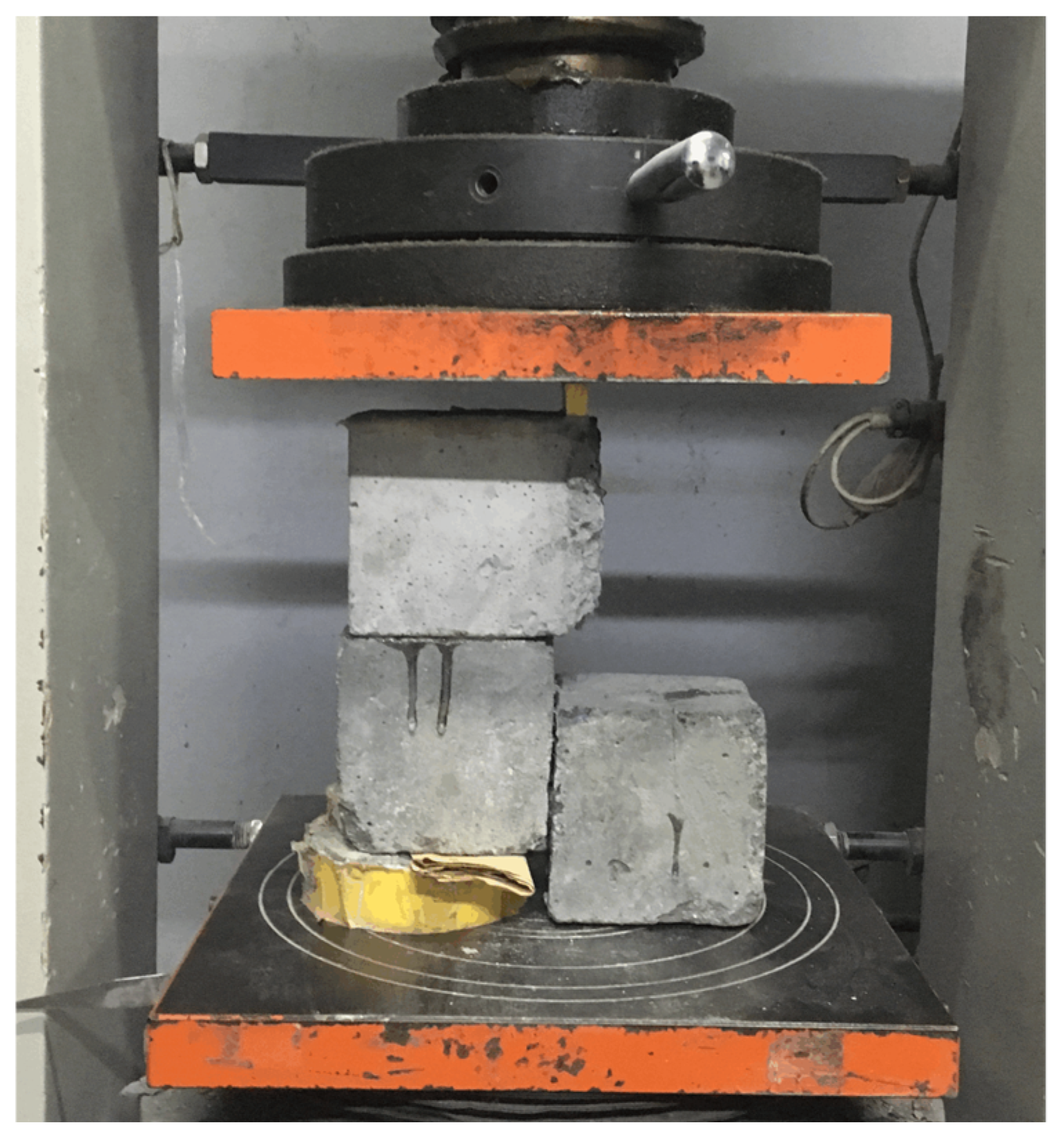
The non-dispersible underwater concrete in this study used Swan brand P.O 42.5 ordinary silicate cement, local potable tap water (Harbin, China), and first-class fly ash. The coarse aggregate was a fine stone with 5–20 mm continuous grading, while the fine aggregate was medium sand with a fineness modulus of 2.59. The UWB-Ⅱ-type anti-dispersant was selected to meet the requirements of underwater concrete casting. UWB-Ⅱ-type anti-dispersant is a concrete admixture composed of water-soluble polymers and surface active substances, etc. It has a strong dispersion resistance and good fluidity, and it is a powder material that can be added to ordinary concrete to form concrete with anti-dispersant properties to resist water scouring underwater. To create the 150 × 150 × 150 mm concrete test cubes, the molds were placed in a water tank (450 mm height) with the top water level 250 mm higher than the top of the test molds. The non-dispersible concrete mix was slowly poured into the molds from the water surface to prevent the mix from hitting the water’s surface or spilling. The mix was continuously fed into the molds until it spilled over the surface of the mold. The test molds were removed from the water tank and left to stand for 5–10 min. After observations were made regarding the self-leveling and self-compaction of the mix samples, both sides of the molds were tapped to release any excess water. The excess mixture on the mold surfaces was smoothed, and the molds were replaced in the water tank for curing. After two days, the cubes were demolded and returned to the water tank for further curing. A conventional concrete mix was used to form a comparative specimen cube and placed in the standard curing room for curing.
3.2. Optimization of NUC Mix Ratio
The mix proportions for the NUC specimens were prepared according to the Chinese standards DL/T5330-2015 [
28] and JGJ 55-2011 [
29], considering the influence of the strength ratio between land and water and the strength loss of casting underwater. The proposed concrete strength grade for the repair lining was C20; therefore, the same strength grade was chosen for the NUC test mix.
The specific design method of the mixing ratio was as follows:
- (1)
Underwater preparation strength () and land preparation strength ():
where
is the design strength standard value of NUC;
is the underwater molding preparation strength of NUC;
is the land molding preparation strength of NUC;
is water and land strength ratio coefficient, and when there are no corresponding test data, if the construction of underwater non-dispersed concrete in the water meets the prescribed free drop,
is taken as 0.7–0.85; and
is the standard deviation of strength.
- (2)
Calculation of water–cement ratio:
where
is the water–cement ratio;
and
are regression coefficients; and
is the 28 d strength of cementitious material.
When the 28 d compressive strength of cementitious material
is not measured, it can be calculated according to the following formula:
where
and
are the fly ash strength influence coefficient and blast furnace slag powder strength influence coefficient; and
is the cement 28 d compressive strength of glued sand.
- (3)
Water consumption and water-reducing agent:
According to the recommended water consumption, is 230 kg and cementitious material is 410 kg.
- (4)
Total amount of cementitious material and amount of each admixture:
The amount of cementitious material per cubic meter of concrete (
) should be calculated according to the following formula:
The amount of mineral admixture will be calculated according to the following formula:
where
is the amount of mineral admixture per cubic meter of concrete in the calculated mix ratio and
is mineral admixture dosage.
- (5)
Determination of the sand rate and calculation of the amount of coarse and fine aggregates:
The sand rate should be in the range of 36–46%, and the sand rate taken in this test is 43%. The calculation is performed using the volume method:
where
is the density of the cement, taking 2900–3100 kg/m
3;
is the density of the mineral admixture;
is the apparent density of coarse aggregates;
is the apparent density of fine aggregates;
is the density of the water and can be taken as 1000 kg/m
3; and
is the percentage of air content in the concrete, which can be 1 when no air-entraining admixture is used.
According to the above program design of NUC, the formulation of C20 concrete is proposed. The basic mixing ratios are shown in
Table 1.
According to the Chinese standard DL/T5117-2021 [
30], combined with the practicality of this topic, the following properties of NUC are selected to measure: fluidity, dispersion resistance, and water–land strength ratio to determine the optimal mixing ratio of NUC. The fluidity is evaluated by measuring slump and slump expansion. The cement loss method and pH value detection method are selected to measure the dispersion resistance of the NUC. The relationship between the tensile strength and compressive strength of the NUC is basically consistent with that of ordinary concrete, and its mechanical properties are evaluated by compressive strength. According to the basic mix ratio of NUC, the comparison tests were carried out by changing the dosage of each component, in which the water–cement ratio was varied from 0.45 to 0.55, the anti-dispersant dosage was varied from 2% to 3%, and the fly ash dosage was varied from 5% to 25%. The optimal mix ratio was determined based on tests and analytical results.
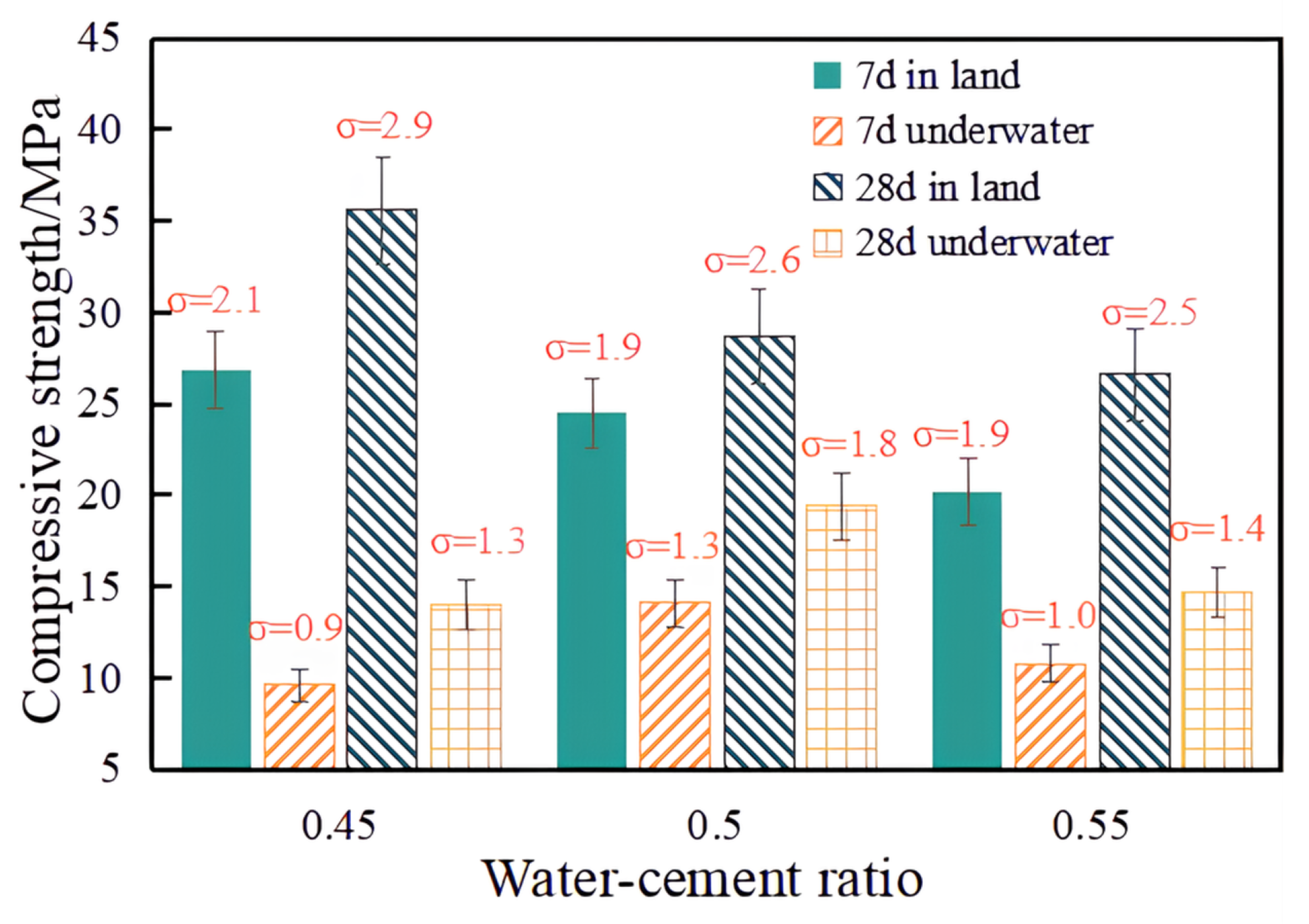
3.2.1. Analysis of the Impact of Water-Cement Ratio
As the water–cement (w/c) ratio is a crucial factor affecting the performance of concrete, this study adopted the one-factor rotation method to determine the effect of the w/c ratio on the performance of the NUC. Three samples were prepared for each mix proportion, where the average compressive strength of the three samples was taken as being representative of that mix ratio. The mix ratios are listed in
Table 2. The effect of the w/c ratio on the flow properties is shown in
Table 3. When the w/c ratio increased from 0.45 to 0.50, the slump and slump expansion increased significantly. In contrast, when the w/c ratio increased from 0.50 to 0.55, the slump and slump expansion increased marginally. This indicates that, when the w/c ratio is in the range of 0.45 to 0.5, the variation in the w/c ratio has a significant effect on the flow properties, whereas a w/c ratio greater than 0.5 has a minimal influence on the flow properties. Furthermore, the variations in the slump and slump expansion results at 30 s and 2 min are within 10%.
Dispersion resistance is the ability of NUC to resist the scouring effect of water, to protect the concrete from excessive cement loss, and to protect the aggregates from segregation when the concrete passes through a water layer during underwater placement. In this study, the pH test method and the amount of cement loss were chosen to reflect the dispersion resistance of the NUC. The results in
Table 2 show that, as the w/c ratio increased, the cement loss percentage and the pH value increased correspondingly, while the anti-dispersion property decreased. This can be ascribed to the change in hydration products and degree of hydration of the concrete with the increase in the w/c ratio, leading to an increase in the pH value of the concrete [
31]. As the total internal cementitious content remained unchanged, the water consumption per unit volume of concrete increased, and the capillaries inside the concrete were filled with water. This resulted in a decrease in the surface tension of the internal particles of the mix, and, as a result, the adhesion and cohesion of the cement paste were reduced.
As indicated in
Figure 3 (where σ represents the standard deviation), the compressive strength of the specimens on land (i.e., not cast underwater) decreased as the w/c ratio increased. The compressive strength of the NUC specimens first increased and then decreased as the w/c ratio increased from 0.45 to 0.55. The NUC specimen with a w/c ratio of 0.45 had numerous honeycomb pockmarks, indicating that the low w/c ratio resulted in less dense concrete, which would, in turn, affect its underwater strength. When the w/c ratio was 0.55, the compressive strength was lower than that of the specimen with a w/c ratio of 0.50. From the above analysis, it can be seen that, when the water–cement ratio was above 0.5, the fluidity was better, which could meet the construction demand, but when the water–cement ratio was above 0.5, the flow performance was not improved by simply increasing the water–cement ratio. At the same time, when the water–cement ratio was 0.55, the dispersion resistance and concrete strength also decreased significantly compared to 0.5. Therefore, it was concluded that the optimal w/c ratio was 0.50.
3.2.2. Analysis of the Impact of Anti-Dispersant
As anti-dispersant dosage is typically from 2% to 3% of the mass of cement [
32]; three mix ratios were used in this study to explore the effect of the anti-dispersant dosage on the properties of NUC. These mix proportions are given in
Table 4. The effect of the anti-dispersant dosage on the working properties of the concrete is listed in
Table 5. The lowest anti-dispersant dosage of 2% resulted in the greatest specimen fluidity, with a 30 s slump of 228 mm and a 30 s slump expansion of 410 mm. As the anti-dispersant dosage increased, the slump and slump expansion were reduced to different degrees, indicating that the NUC fluidity was weakened with the increase in anti-dispersant. When the anti-dispersant dosage was 3%, the corresponding slump and slump expansion were 193 mm and 372 mm, respectively. Due to the need for the good fluidity of non dispersed concrete during on-site construction, when the dosage was 3%, the fluidity of concrete no longer met the requirements of its construction specifications.
The results in
Table 4 show that, as the anti-dispersant dosage was increased, the cement loss and pH test values decreased, indicating that the corresponding anti-dispersant properties improved. However, once the dosage reached 2.5%, an increased anti-dispersant dosage had a minimal effect on the NUC properties.
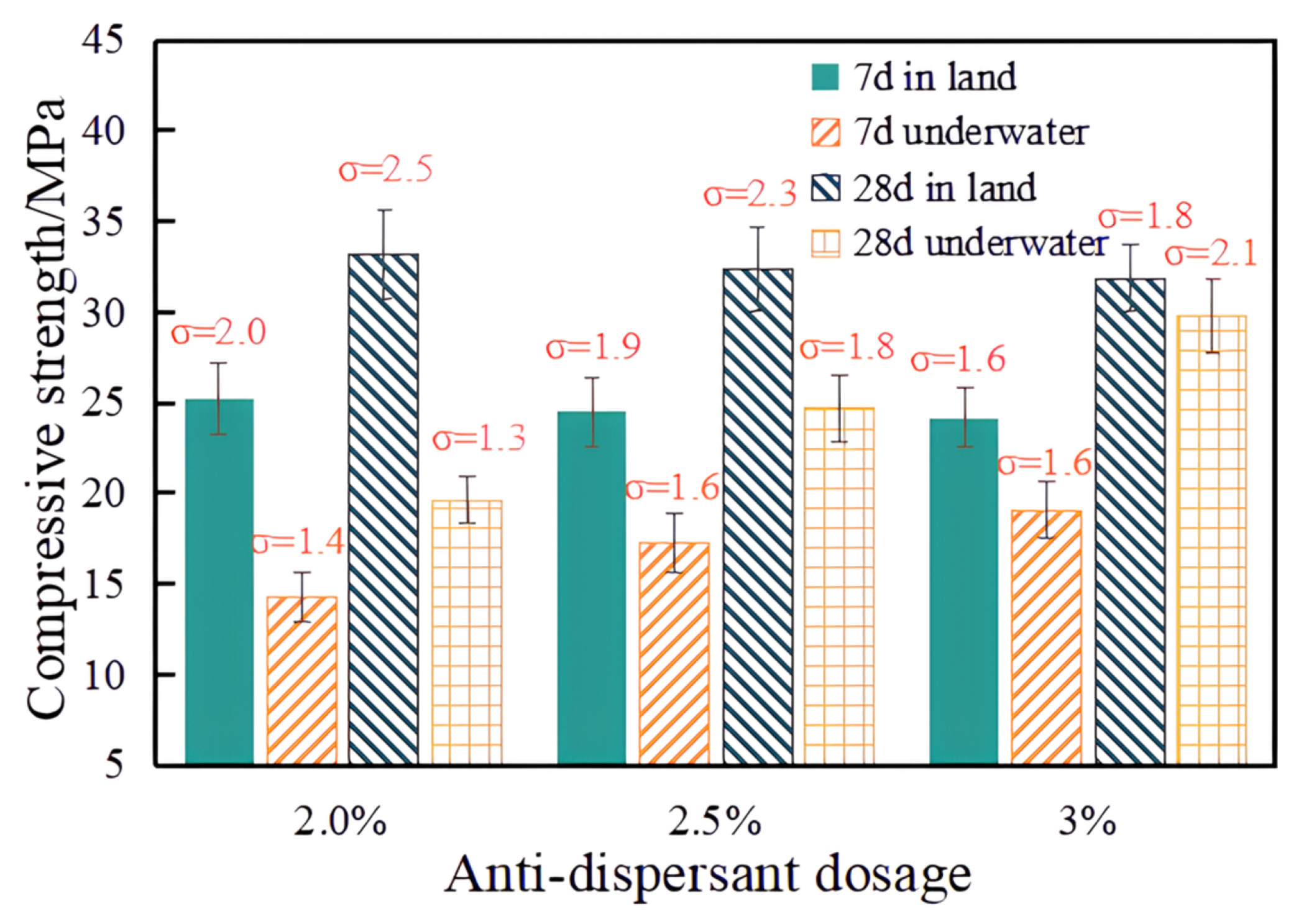
As indicated in
Figure 4, as the anti-dispersant dosage increased, the 28 d compressive strength of the NUC increased from 19.6 MPa at a 2% dosage to 28 MPa at a 3% dosage. With the increasing anti-dispersant dosages, the corresponding water and land compressive strength ratios also tended to increase, with greater rates of increase. At a 3% dosage, the strength ratio of land and water was approximately 0.9. In contrast, as the anti-dispersant dosage increased, the strength of the land concrete decreased slightly, as shown in
Figure 4. In the initial stages of cement hydration, a large quantity of viscous cellulose is present in the cement, thereby increasing its incompletely hydrated cement particles. With the addition of anti-dispersant, the 28 d strength was therefore slightly reduced.
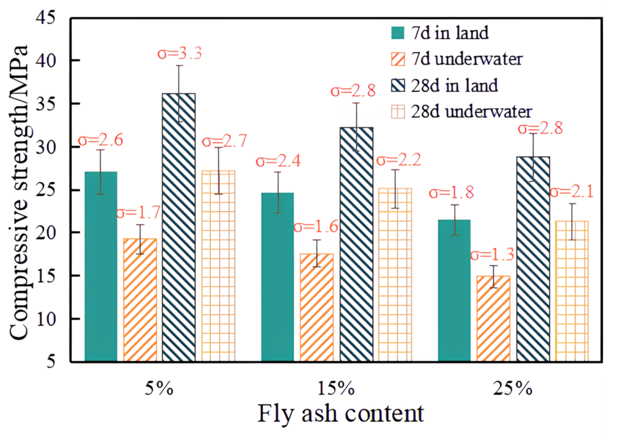
3.2.3. Analysis of the Impact of Fly Ash
Incorporating fly ash into concrete can reduce the cost by replacing part of the cement while simultaneously improving the flowability of the concrete. A one-way rotation test was used to study the effect of fly ash admixture on the performance of NUC to determine the optimum admixture ratio of fly ash. The fly ash dosages were set at 5%, 15%, and 25% (mass percentage of fly ash and cement); the ratios are given in
Table 6.
The effect of fly ash on the workability of concrete is shown in
Table 7. It can be noted that the addition of fly ash improved the slump and slump expansion of NUC. When the fly ash dosage was 25%, the corresponding 2 min slump and slump expansion were 248 mm and 430 mm, respectively. The variation in the slump and slump expansion over 30 min was within 10%, indicating a good construction performance.
From the results given in
Table 6, it can be seen that, as the fly ash dosage increased from 5% to 25%, the cement loss and pH test values decreased. In ordinary concrete, when cementitious material is mixed with water, small flocculating groups are formed, which are unstable and easily dispersed. The main component of UWB-Ⅱ-type anti-dispersant is an organic polymer compound with long carbon chains. Once the polymer compound is added to the concrete, it has a strong adsorption effect. It can adsorb many particles simultaneously, forming a net structure and providing a bridge to form a larger flocculating group. This larger flocculating group is more stable and can resist the external water’s scouring effect. Fly ash particles with high surface areas are attracted to the anti-dispersant on the long carbon chain package. They fill the long carbon chain gaps and increase cohesion, resulting in more viscous concrete. At the same time, the fly ash and cement particles are surrounded by the mesh structure, making the NUC into a denser and more uniform flocculation structure. This improves the anti-dispersive properties and enables the NUC to resist the scouring effect of the external body of water.
As shown in
Figure 5, the increase in the quantity of fly ash in the mix reduced the strength of the concrete. Although fly ash is not involved in the chemical reaction of the hardening of the cement paste in the early stages, in the later stages, fly ash reacts with the hydration products of cement, thereby relatively increasing the concrete’s strength. When the dosage of fly ash is within the 5–25% range, each 10% increase in fly ash resulted in a corresponding 10% reduction in compressive strength at 28 d for the underwater concrete. When the quantity of fly ash was increased, although the strength of both the underwater and land concrete decreased, the decrease ratio of land and water strength was similar. Therefore, it was concluded that the inclusion of fly ash had a similar degree of influence on the land and underwater strength. Considering the strength and fluidity, a 15% fly ash content was determined as the optimal content of this project. When the strength requirement was low, but the fluidity requirement was high, 25% fly ash can be appropriately selected as the dosage for concrete. When the related project has higher requirements for NUC strength, the design strength can be improved to obtain the basic mix ratio of higher-strength NUC according to the determination method of the basic mix ratio of NUC in this paper. Through the test for ratio optimization, this results in higher-strength NUC.
3.2.4. Optimal Mix Ratio
From the analysis results, the optimal mix ratio of NUC for underwater lining repair was determined, as listed in
Table 8. For the concrete obtained using this mix ratio, its slump and slump expansion satisfied the requirements of flow performance, the cement loss and pH test value satisfied the requirements of anti-dispersive performance, and the 7 d and 28 d underwater compressive strengths of 17.6 MPa and 25.1 MPa satisfied the requirements of the project.


