Article

Study on Resourceful Treatment and Carbon Reduction Intensity of Metro Shield Slag: An Example of a Tunnel Interval of Shenzhen Line 13

1
China Construction First Group Corporation Limited, Shenzhen 518002, China
2
Key Laboratory for Resilient Infrastructures of Coastal Cities, Ministry of Education, Shenzhen University, Shenzhen 518060, China
3
Shenzhen Key Laboratory of Green, Efficient and Intelligent Construction of Underground Metro Station, Shenzhen 518060, China
*
Author to whom correspondence should be addressed.
Buildings 2023, 13(11), 2816; https://doi.org/10.3390/buildings13112816
Submission received: 10 October 2023 / Revised: 26 October 2023 / Accepted: 1 November 2023 / Published: 10 November 2023
(This article belongs to the Special Issue Low-Carbon and Green Materials in Construction—2nd Edition)

Abstract

:
At present, the scale of subway construction in Chinese cities has reached a new height, and the shield slag produced by it has also surged year by year. Untreated subway shield slag not only occupies the space resources of the country, but also carries CO2, which causes negative impacts on the environment and which, as a result, is not conducive to the realization of the goal of the national “double-carbon” strategy. Therefore, how to effectively manage the shield slag produced by subway construction has become a scientific problem that needs to be solved urgently. In order to scientifically dispose of metro shield slag and quantify the carbon reduction intensity of its disposal, based on the new shield slag integrated recycling technology, and taking a tunnel interval of Shenzhen Line 13 as an example, this study systematically sorted out the shield slag disposal process, clarified the management path of the on-site resource utilization of slag, and quantitatively compared the carbon emissions before and after the treatment as well as carbon reduction intensity. The results show that the on-site disposal process is basically feasible, and that, it is possible to achieve a shield structure slag reduction of resource products and mud cake water content of less than 40% of the target, in the case of 160,000 m3 of shield structure slag resource utilization after a total carbon reduction of about 4240.13 t CO2, of which each preparation of 1 m3 of recycled bricks can bring about a benefit of carbon reduction of 240.09 kg CO2. Compared with the conventional mud head truck slag disposal, shield structure slag resource utilization can save a utilization cost of about 10.4 million yuan, meaning that, in terms of economic and social levels, this method can achieve good benefits. This case verifies the feasibility of the new technology, and the results of the study can provide experience for other metro projects’ shield slag resource utilization, and provide stakeholders with a shield slag recycling management strategy for government departments to scientifically formulate metro shield slag management policy to provide data support.

1. Introduction

Over the past decade, China’s metro operating line reached a length of about 9206.8 km, and the construction scale has reached a new height. At the same time, this construction process produced a large number of metro shield slag, the cumulative output of which exceeded 270 million m3, of which the shield slag mainly includes gravel, slurry, and other wastes [1]. Further, at present, China’s metro shield slag utilization rate of resources as a whole is low, and there is still a large gap between China and other countries [2,3,4,5,6,7,8], which is a great pressure on China’s urban environmental management. In order to realize the “14th Five-Year Plan” target [9] and set up a good social image, we need to further study the recycling of urban subway shield slag. The rational disposal of metro shield spoils can also reduce carbon emissions, fulfill the goal of sustainable development [10,11], and lay a solid foundation for China to achieve the goal of reducing carbon dioxide emissions to 18% within the planning period [12,13].
According to the statistics of Shenzhen Municipal Bureau of Housing and Urban Development, shield slag accounts for about 75% of construction waste. At present, the disposal of shield structure spoils in Shenzhen is mainly based on simple landfill, which not only occupies a large amount of land resources and makes it difficult to meet the requirements of the urban environmental protection system [14], but also causes soil and water pollution due to the infiltration of surface water, and is prone to slope destabilization under rainfall conditions. As of 2030, in Shenzhen City, there is still more than 500 km of subway construction planned, but at present, in Shenzhen, there are only five companies to carry out the shield slag resources disposal business [8]. Thus, processing equipment integration and the modularization of a low, disposal process flow is a relatively important issue, among others, and there is an urgent need to explore standardized technology paths and systematic disposal processes. At the same time, it is urgent to explore standardized technology paths and systematic disposal processes, while reducing the release of carbon dioxide during the extraction and transportation of raw materials to help achieve the “dual-carbon” development goal [10,15].
After mining the literature, the current research of some scholars on shield slag from metros mainly focuses on confirming its environmental benefits [16,17,18,19,20,21,22], such as Li [23] and others, who confirmed the advantage of disposing shield slag in reducing global warming based on the whole life cycle approach, and Fořt [24] and others, who quantified the recycling value of discarded slag from the environmental point of view. Secondly, some scholars have also studied the properties of shield slag and modified it for secondary utilization according to different properties, such as Rondinel [25], who converted the sand in waste slag into acoustic walls and filler for reuse, and Yang et al. [26], who used the waste slag to produce grouting materials for the back walls of shield tunnels with different water-to-cement ratios. Voit et al. [27] applied the shield material to replace the conventional aggregate, which is now successfully applied in the base tunnel in Switzerland. Therefore, the former research is mainly limited to a single verification of the environmental benefits and recycling value of disposing of shield tunnels slag [28], but it has not formed an integrated recycling process, nor has it considered whether the integrated equipment is adapted to on-site operation in depth, nor has it compared the cost of disposing of slag with the economy of recycling, and it lacks a certain degree of popularization [29]. In summary, in order to make up for the above research gaps and limitations, this study establishes an integrated disposal process of slurry separation—sand washing—filtration of shield sludge, and conducts empirical research on the site of a section of Shenzhen Metro Line 13 tunnel interval. The results show that the work method is applied to a high degree in the field, the recycled products all meet the emission standards of Shenzhen City, and the total carbon reduction of 160,000 m3 of shield slag in the interval reaches 4240.13 t. Compared with the traditional disposal method, the resourceful disposal of slag saves a total of about 10.4 million yuan in economic costs, which achieves a good benefit at both the economic and social levels. The results of this study can provide reference for other metro projects, provide management strategies for stakeholders, and provide data support for local governments to scientifically formulate relevant policies, and the carbon reduction effect brought about will also help China to realize the goal of “dual-carbon” as soon as possible.

2. Research Methods

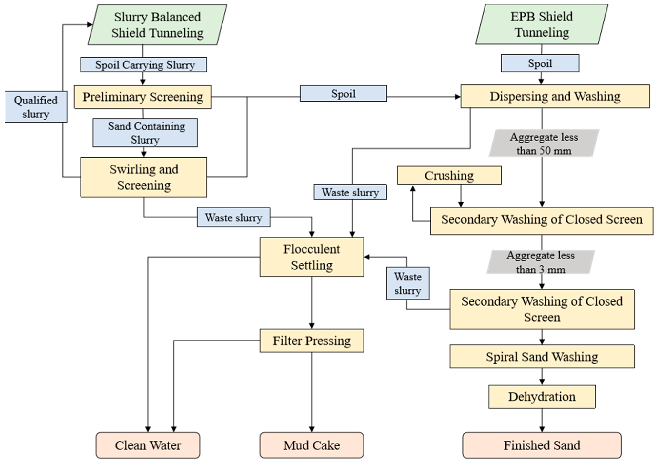
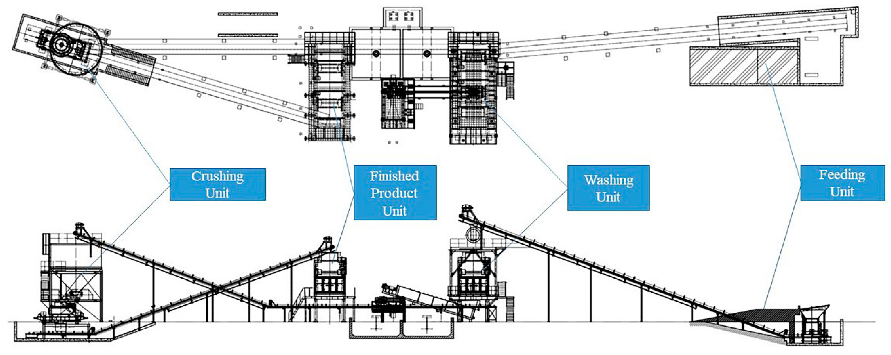
2.1. Metro Shield Sludge Integrated Recycling Technology

In this study, a set of integrated recycling technologies for sand-bearing strata, which can dispose of the sludge produced by mud-water balanced shield (SBS) and earth-pressure balanced shield (EPB), is proposed, which mainly consists of several systems, including mud-water separation, sand washing, pressure filtration, and light-wave brick making. The detailed operation flow of this method is shown in Figure 1.
The recycling step mainly includes separating the mud sand and waste slurry produced by shield machine digging. Qualified slurry is provided to the shield machine for recycling, and the separated waste soil is transported to the sand washing system for secondary treatment; the sand washing system physically disperses, vibratory sieves, and impact crushes the waste soil separated from the former along with the earth-pressure shield residue to make the fine sand less than 3 mm, and the vibration is used to reduce the water content of the net sand; the waste liquid is flocculated and precipitated in the filter-pressing system by adding the polymer, the waste liquid is flocculated and precipitated by chemical reaction, the top filters out the water, which can be reused for sand washing or on-site cleaning, and the bottom forms a slurry that is transported to the filter press for reuse, which is pressurized to separate out the dry soil, which can be made into environmentally friendly building materials for reuse. Finally, in the light-wave brick-making system, the dried mud cake is transported to the light tunnel for dehydration and solubilized with additives, which makes the cross crystallization of soil mud micro-particles and cement micro-particles more rapid; then, through the shaping system, it is pressed into standard bricks by the static pressure device for brick making.

2.2. Case Background Introduction

The project is located in Gongming North Road, Guangming District, Shenzhen City, located in a geographical area with a sand content of more than 40% of the stratum, mainly including fine sand, medium-coarse sand, gravelly sand, and other water-content strata, as well as hard-plastic sandy clayey soil, granite, sandstone, mudstone, and other strata with a high content of mud. The overall geological complexity to the medium and fine particles are dominated by the shield slag soil with a high content of water, and the mud has a large number of characteristics. The case has 4 stations and 3 intervals and the total length of the interval is about 2361.6 m, among which the mud-water balanced shield is 1334.3 m long, the soil pressure balanced shield is 1027.3 m long, and the total cubic volume of the shield slag entity is 158,000 cubic meters. Among them, the diameter of the shield machine for double line excavation is 6.48 m, the digging speed is about 3.6 m/h, and the mud discharge is about 1.00 m3/h.

2.3. Information on Main Materials and Equipment Parameters

The integrated disposal system proposed in Section 2.1 specifically includes two mud-water separation systems, one sand washing system, and five filter-pressing systems in order to ensure the resourceful disposal of shield spoils along with construction. In addition, the main materials added include polyacrylamide for mud dewatering, defoamer, and lubricating grease for equipment.
The mud-water separation system mainly consists of a mud-water separator, modulation slurry equipment, mud-water purification equipment, a processing power of 1200 KW·h, using a double-layer pre-screening structure and a high-excitation force exciter on the sludge for the initial screening, power up to 15 KW, and a speed of 960 rpm, and it can deal with a flow rate of dirty slurry 1000 m3/h. Immediately after the sand and mud separation by the first cyclone, the second cyclone de-sludge unit conducts dewatering and grading. The sieve hole of the primary cyclone sand sedimentation system is 0.4~0.6 mm, the pressure drop of the cyclone is 0.12~0.18 Mpa, the single processing capacity reaches 480~650 m3/h, and the cutting point of the cyclone is 74 microns; the sieve hole of the secondary cyclone sludge removing unit is 0.4~0.6 mm, the pressure drop of the cyclone is 0.15~0.25 Mpa, the single processing capacity reaches 32~42 m3/h, and the cutting point of the cyclone is 20 microns. The cyclone cutting point is 20 microns, and the overall separation efficiency is as high as 85% or more to achieve good separation of fine stone powder and silt clay.
The sand washing system mainly consists of feeding equipment, an impact crusher, a flat water screen, a closed screen, a spiral sand washer, a dewatering screen, etc., of which the impact crusher power is about 200 t/h, and it is mainly crushed into the slag for stones with a diameter of less than 50 mm, through the sieve diameter of 4 mm of the flat water screen for initial screening. For those with a diameter of 3 mm, the closed screen is used for screening again, while sand that is less than 3 mm sand can be moved directly through the vibration dewatering to form a finished sand to use. For 3 mm ≤ stone diameter ≤ 50 mm, the stone is once again crushed by the crusher, and the above steps are repeated until all stone is transported to the spiral sand washer, which has a spiral sand washer power of up to 180 m3/h, and ultimately is run through the sieve with a diameter of about 120 microns of dewatering sieve dehydration in order to control the residual mud moisture content and the water content of the residual mud. The water content of the residual sludge is controlled to ensure that the water content of the external slag is less than 40%.
The filter press system mainly consists of a filter press, slurry pump, slurry tank, and control system, in which the diameter of the pumping pipeline is divided into two sets of 100 mm and 300 mm, the capacity of the slurry concentration tank is 1500 m3, and the total power of the final filter press unit is 675 KW·h, with the daily capacity being up to 1200 m3, which can fully satisfy the requirements of waste slurry pool storage and filter press processing requirements.
The light-wave brick-making system mainly consists of loading equipment, a crusher, a light tunnel dehydration system, a light mixing system, a molding system, a hardening system, and stacking equipment. Its main function is to make the slurry with a moisture content less than 50% into finished bricks for secondary use through light tunnel dehydration, mixing, additives, and so on. The process takes about 25 min, 200 t of slag can produce 80,000 standard bricks per day, the compressive strength of the finished bricks reaches 16~16 Mpa, and the flexural strength of the bricks reaches 2.7~3.5 Mpa.

2.4. Data Collection and Processing

In this study, the carbon reduction benefits of resource utilization are mainly categorized and calculated according to electricity, oil, and water consumption. Since water consumption can be recycled on-site, our study mainly focuses on the statistics of daily machinery oil consumption and electricity consumption data from the on-site control center, and ignores the water consumption part for the time being. The average daily fuel consumption of machinery, electricity meter data, and other records are mainly used to estimate the consumption within the specified working period.
Since the above recycling device can produce recycled sand and recycled building materials, there is also a partially compensated carbon benefit, and the carbon emission calculation of the resourceful disposal is shown in Equation (1).
C e R = V × E r × E e + r M r × E r i E i × E e
where CeR is the carbon emissions in the process of resource utilization of subway shield slag, measured in kg CO2e;
V is the volume of subway shield slag, measured in m3; Er is the energy consumption of resource treatment of 1 m3 subway shield slag, measured in KW·h/kg;
Mr is the mass of the first kind of added material, Er is the carbon emission factor of the rth kind of added material, measured in kg CO2e/t;
Ei is the energy consumption in the production process of replacing the primary building materials of type i, measured in kg, L, KW·h;
Ee is the carbon emission factor of energy, measured in kg CO2e/(KW·h), kg CO2e/kg.
The carbon emission generation of the direct landfill method mainly includes the energy consumption of transportation and mechanical landfill equipment. The carbon emission calculation formula of the traditional disposal method is shown in Equations (2)–(4).
C e t = n M × D i × E i × F y
C e M = m n T i × R i × E e
C e L = C e t + C e M
where Cet is the carbon emissions from transportation energy consumption of the transport, in kg CO2e;
M is the mass of subway shield slag, measured in t;
Di is the subway shield slag using the ith mode of transportation of the average transportation distance, measured in km;
Ei is the carbon emission factor per unit mass transportation distance under the transportation of the first way, measured in 0.129 kg CO2e/(t km);
Fy is the empty vehicle turnback factor, and n is the type of transportation mode;
CeM is the carbon emissions from energy consumption of construction machinery involved in landfill disposal, in kg CO2e;
Ti is the consumption of the ith type of construction machinery unit;
Ri is the energy consumption per unit shift of the ith type of construction machinery, measured in KW·h/shift, kg/shift;
m is the type of construction machinery; CeL is the carbon emission in the process of subway shield soil landfill disposal, measured in kg CO2e.
Substituting the average daily fuel consumption and electricity consumption data into the formula, the final calculation obtained that the carbon emission of the resource utilization stage of the subway shield slag is about 4451.6 t CO2, while the carbon emission of the direct landfill elimination and disposal is about 8691.7 t CO2, and the overall benefit is reduced by 51.2%, which is a very optimistic finding.
In terms of economic benefits, the study is calculated according to several aspects, including construction and installation costs (A), production and operation costs (B), slag disposal costs (C), and recycled sand compensation (D). Rm represents the cost after resourceful disposal, calculated as shown in Equation (5).
R m = A + B + C D
Among them, the construction and installation project cost is calculated based on the procurement cost of basic equipment and supporting maintenance facilities provided by the procurement department, and the production operation mainly includes water and electricity costs, labor costs, and material testing costs, of which water and electricity costs and labor costs are calculated according to the average monthly expenditure multiplied by the total construction period of 16 months and the material testing is calculated according to the actual occurrence of the quality control requirements. The disposal fee of untreated shield structure residue is calculated according to RMB 320/m3, half of the remaining volume of the soil volume after reduction, and it has to be calculated according to the dry soil disposal fee of RMB 280/m3. The total amount of shield structure residue treated by this process is about 160,000 m3, and 80,000 m3 of dry soil is left after reduction. Secondly, the amount of recycled sand is calculated according to the sand content and actual output of different strata, and a total of about 50,000 m3 of recycled sand was recycled in our sample. In the end, the traditional disposal cost totaled 51.2 million, and the cost of the resourceful disposal of residual soil totaled 46.21 million, saving a total of 4.99 million yuan.

3. Results

3.1. Detailed Recycling Process

The detailed steps for the recovery of shield slag from the integrated system are shown in Figure 2, where the main materials used and the related equipment parameters are referenced to the contents of Section 2.3.

3.1.1. Preliminary Slurry Screening

The spoil excavated by the slurry shield method carries slurry into the primary screen, and the diameter of the screen hole is 3 mm. This process adopts a double-layer pre-screening structure with a downhill angle, the upper layer being 10 mm thick and the lower layer being 5 mm thick. The coarse screen separates the coarse particles in the slurry from the sand. The vibrating screen screens out the spoil with a particle size greater than 3 mm from the slurry of the shield machine, and the spoil falls to the slag yard for stacking. If the particles over 3 mm, and the moisture content of the residue is less than or equal to 30%, it can meet the direct external transport. The remaining sand containing slurry is pumped through the pipeline to the next step for screening.

3.1.2. Slurry Swirling and Screening

The sand containing slurry obtained from the preliminary screening is stored in the slurry storage tank. When the liquid level in the slurry tank exceeds the set start liquid level line, the slurry pump and cyclone are started and the slurry enters the primary cyclone for centrifugal grit separation. The sand particle size that can be treated is from 3 mm to 74 microns. The slurry flows automatically to the bottom of the primary screen, and then flows through the sieve hole with a diameter of 0.5 mm before reaching the next stage of the cyclone. The secondary cyclone can handle particle sizes ranging from 74 microns to 45 microns. The secondary sieve’s hole diameter is 0.3 mm. The fine sand is separated and dropped to the slag yard for stacking. After separation, the qualified slurry is used for shield tunneling, and the waste slurry exceeding the standard is filtered. The specific operating system is shown in Figure 3.

3.1.3. Dispersing and Washing

The main purpose of dispersing and washing is to disperse sand and stone, and remove slurry lumps. The spoil separated from the first and two steps falls into the washing tank at the bottom of the hopper, and then is transferred to the top of the horizontal screen. The water pipe at the upper part of the horizontal screen is opened to wash the spoil, and the sand and gravel with a diameter greater than 50 mm are smashed through the crusher. Sand with a diameter less than 50 mm is transported to the next step by belt for secondary water washing of the closed screen. The detailed operating system is shown in Figure 4.

3.1.4. Secondary Washing of Closed Screen

In this step, the vibration motor of the closed screen is started in turn, and the starting time interval between the two motors is 6 s to 8 s. At the same time, the high-pressure water for washing is turned on, and the belt conveyor for feeding is started after the vibrating screen operates stably. After feeding, the sand with a particle size less than 3 mm can be washed by high-pressure water above the closed screen to remove slurry in the aggregate. The sand with a particle size less than 3 mm is naturally dropped into the water tank of spiral fine sand for the third flushing, while the sand with a particle size greater than 3 mm is transported to the impact fracture by the belt for crushing and shaping.

3.1.5. Crushing

The sand with a particle size greater than 3 mm is screened out by the closed screen in the previous link and stored in the feeder on the upper part of the impact broken by the conveyor belt. When the storage weight of the feeder exceeds 100 tons, the lower crusher can be started for crushing and shaping. This causes the sand with a particle size less than 3 mm to easily discharge from the discharge pipe, through a return belt into the sand washing machine to form a circulating sand-making process.

3.1.6. Spiral Sand Washing

The spiral sand washer is mainly composed of a motor, feed inlet pipe, spiral blade, water tank, and slurry outlet. Before starting the motor, sufficient water must be added to the water tank. When the machine runs smoothly, the fine sand screened by the closed screen will be sent to the water tank through the feed inlet. Sand is washed away by currents moving in parallel and in the reverse direction. The sand is scoured and desilted by the water flow in the forward and reverse directions simultaneously. When the spoil content of the slurry is large, the sewage can be cleaned and then the water can be injected again to wash the sand again. The slurry and sewage obtained during cleaning are discharged through the slurry outlet. Clean sand is pumped to the discharge port through spiral blades and falls into the vibrating dewatering screen for dehydration.

3.1.7. Dehydration

After the dehydration screen is started and stabilized, the clean sand will fall into the sieve plate of the dehydration screen. The water content of the sand is reduced to less than 4% after dehydration. The dehydrated sand is transported to the finished sand yard by belt.

3.1.8. Flocculent Settling

This step is mainly aimed at the slurry in slurry shield and slurry produced during the sand washing. After starting the slurry pump, polyacrylamide is automatically added to the concentration tank to cause the chemical reaction. After the auxiliary agent fully reacts with the slurry, the flocculation stratification effect will be formed after standing. Due to the mixed impurities of the thick slurry, its overall density is higher than that of the clean water, and it is at the bottom. Clean water is on the top. The slurry pump is turned on at the bottom of the concentrator, and the concentrated slurry at the bottom is pumped to the filter press for further processing. The supernatant of the upper layer flows naturally into the clean water pool through the sink for recycling.

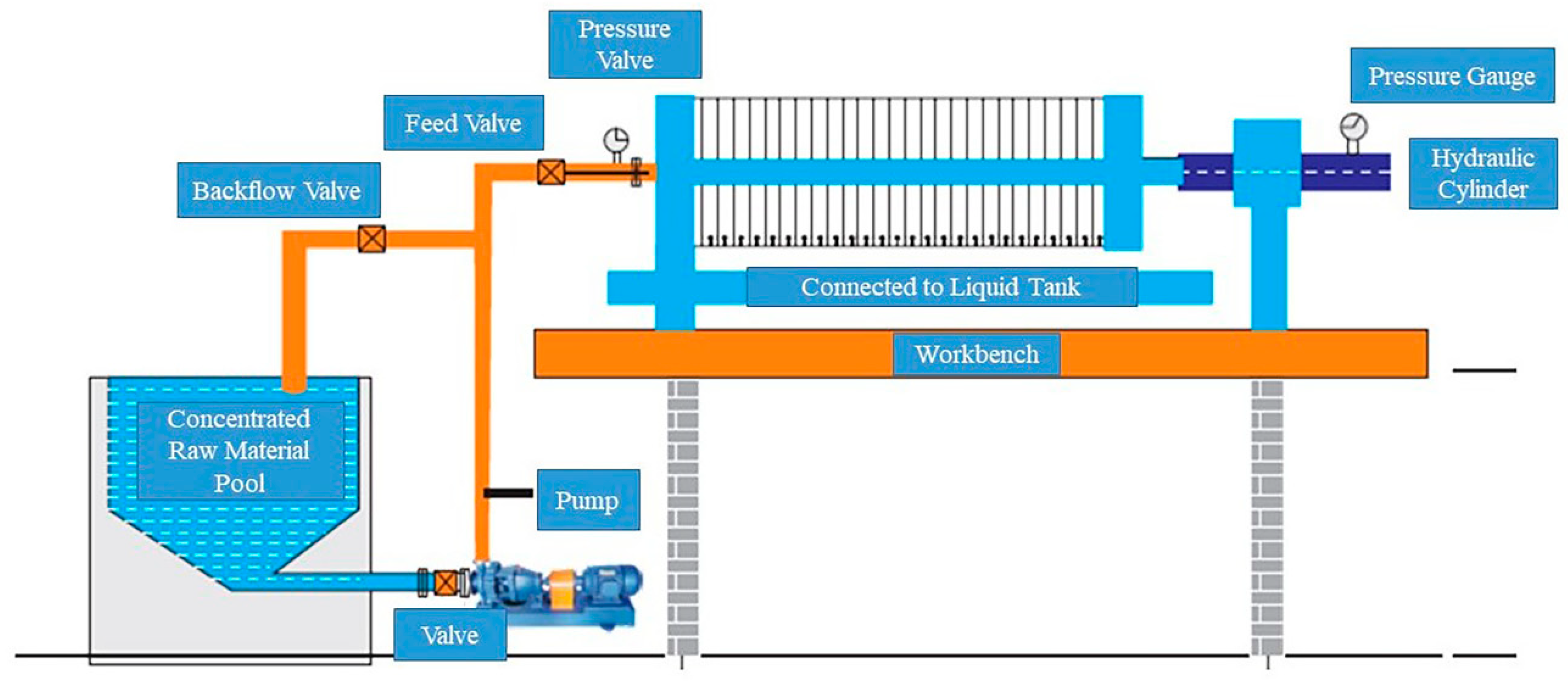
3.1.9. Filter Pressing

The filter press system is mainly composed of a filter press, air compressor, slurry pump, slurry tank, and control system. After the slurry pump sends the slurry in the underflow flow slurry tank to the closed chamber between the filter plates of the filter press, the solid particles of the slurry are intercepted by the filter cloth and gradually enriched to form the filter cake, while the filtrate flows out through the filter cloth and enters the filtrate collection tank. When the liquid level in the tank reaches a certain height, the drainage pump will be opened to discharge the filtrate. When the liquid level in the tank decreases to a certain height, the drainage pump will stop. The remaining filtrate is used for pipe flushing. The detailed filter pressing system is shown in Figure 5.

3.2. Economic and Environmental Analysis

Calculated based on the rules introduced in Section 2.4, the cost of shield sludge resourcing mainly includes the construction and installation costs, production and operation costs, recycled sand revenues, and waste treatment costs. Although the cost indicators of the first three are greater than conventional treatment, the cost savings of waste treatment are much greater than the first three. Substituting the above costs into the formula, the total cost of shield gangue resources is 46.21 million yuan, as shown in Table 1. Compared with the total cost of conventional disposal of 51.2 million yuan, there is a reduction of 4.99 million yuan. The economic benefits are more significant.
In addition, CO2 emission was adopted as the environmental impact evaluation index. The carbon emission of the whole life cycle of the shield slag was evaluated. The total conventional carbon emissions of the project were compared with the total carbon emissions after reduction. Expenditures by sub-item are shown in Table 2. It is calculated that about 160,000 cubic meters of shield soil recycled in this project can reduce CO2 emissions by 48.2%. Overall, the closed-loop management of waste on-site treatment has been realized to achieve the near-zero emission of solid waste and reduce carbon dioxide emission.
After the calculation of the formula, the final results of the indicators are shown in Table 3.

4. Discussion

The above content describes in detail the recycling steps of mud-water balance shield sludge and soil-pressure balance shield sludge, and analyzing the economic and environmental benefits, it is not difficult to find that the resourceful disposal of waste shield sludge is optimistic. Through the recycling process, the sludge and mud are eventually transformed into resourceful products, such as treated water, mud cake, and regenerated sand, which can be reused in the construction as shown in Figure 6.
The two reasons behind the positive results are mainly that: on the one hand, the policy plays a leading and restraining role. In recent years, China has promulgated a series of laws and regulations such as the urban construction waste and engineering slag disposal management regulations and related solid waste pollution prevention and control law [13], which have increased the control of subway engineering slag and at the same time enhanced the incentives for the resourceful disposal of slag, which causes the construction enterprises comply with the direction of intensive resource conservation [11,30]. On the other hand, with the social happiness index, the pursuit of the high-quality social development concept has been deeply rooted in people’s hearts, and practices such as following the sloppy method of slag landfill will affect the living environment of local residents [31,32]. Therefore, the method introduced in this study is an inevitable way for enterprises to explore the path of resourceful treatment of shield slag [33].
Since our data project the consumption during the construction period by counting the electricity meter and the fuel consumption of machinery, and the process did not include the water consumption, the data are still not comprehensive enough. Secondly, there are many situations on the construction site such as delays due to non-essential factors and midway changes, and it is inevitable that some data will be lost in the process of on-site collection, resulting in the ambiguity of some of the characteristics of the shield slag. In addition, this paper only analyzes a section of Shenzhen Metro Line 13, not the other sections of the line for collection and analysis, so there is still room for improvement in the resourcefulness of metro shield slag. Future research can be based on the characteristics of the slag and slurry materials to establish classification and grading standards for processing and make it easy to count the consumption; secondly, the water consumption data can also be added to make the results of carbon reduction calculations more accurate. What is more worth thinking about is that, in the shield structure sludge environmental protection treatment method, the form of sludge will be converted between solid and fluid, and the treatment process of the various sub-systems and the various equipment, if there is no fusion of parameter matching, will cause pool or pipeline silt blockage, damage to the equipment, cyclone pressure failure, and other back problems. Then, the system would not be able to match the stability of the work, and there is no guarantee of the recovery of the quality of the product and the output. The system will not be able to work stably for a long time, and then the quality and yield of the recovered products cannot be guaranteed.
In conclusion, the recycling of construction waste in the construction industry is unavoidable, which is conducive to environmental protection and the conservation of natural resources [34]. In terms of reducing carbon emissions, this method has achieved remarkable results. The overall carbon emission of 160,000 m3 shield soil of the project is 51% lower than that of the whole project, which positively responds to the goals of “peak carbon dioxide emission” and “carbon neutrality”, and positively responds to the policy of “zero-waste city”, in a way that is replicable and applicable.

5. Conclusions

The method described in this study is a more complete shield soil resource recycling and disposal system and, after the above treatment, the shield soil in the studied case has been harmlessly disposed of. The method also creates two methods of slurry dewatering for brick-making and coarse aggregate extraction for recycled sand, with a high overall processing efficiency and good separation effect. Compared with conventional shield soil disposal, the process saves about 4.99 million yuan in cost, with significant economic benefits, and the carbon reduction effect is more obvious, which is in line with the national strategy and policy requirements. This article also provides information on project site information, stratigraphic conditions, and equipment parameters, with the aim of facilitating reference for other readers, as well as providing recycling experience for construction sites with similar geologic conditions, and shield soil recycling management strategies for stakeholders. It provides basic data support for government departments to scientifically formulate shield damage management policies for metro projects.
In order to better promote the application of the described technology process on a large scale, we suggest doing a good job of geological exploration, according to the results of the geological survey, to be equipped with suitable equipment parameters, especially the shield slag resource processing system of the fluid parameter matching problem, the articulation of the various systems together. In this way, the site can be further improved to the degree of integration and modularity of the equipment, ensuring better data acquisition and control and the stability and balance of the system, and avoiding the problem of machine downtime. In this way, there is no need to change the operating process, only a need to match the adaptive parameters of the system so that it can be widely used, and in order to more vigorously promote the transformation of society to high-quality development, and to promote the country’s early realization of the planning period of the goal of carbon reduction.

Author Contributions

Conceptualization, G.C.; Data curation, G.C. and W.L.; Investigation, Y.L. and C.W.; Methodology, W.L. and F.Y.; Software, T.C.; Supervision, Z.W.; Visualization, Y.L. and C.W.; Writing—original draft, Z.W. and Y.L.; Writing—review & editing, F.Y. and T.C. All authors have read and agreed to the published version of the manuscript.

Funding

This research was funded by the National Natural Science Foundation of China, grant number 72001148; and the Programme of Shenzhen Key Laboratory of Green, Efficient and Intelligent Construction of Underground Metro Station (Programme No. ZDSYS20200923105200001).

Institutional Review Board Statement

Not applicable.

Informed Consent Statement

Not applicable.

Data Availability Statement

The data presented in this study are available on request from the corresponding author.

Acknowledgments

The authors thank the editors and anonymous reviewers for their valuable and constructive suggestions for improving this paper.

Conflicts of Interest

Authors Gang Chen, Wei Li, Fangsheng Yang, and Taibo Cao were employed by the company China Construction First Group Corporation Limited. The remaining authors declare that the research was conducted in the absence of any commercial or financial relationships that could be construed as a potential conflict of interest.

References

  1. Yu, C.; Zhou, A.N.; Chen, J.; Arulrajah, A.; Horpibulsuk, S. Analysis of a tunnel failure caused by leakage of the shield tail seal system. Undergr. Space 2020, 5, 105–114. [Google Scholar] [CrossRef]
  2. Massoudinejad, M.; Amanidaz, N.; Santos, R.M.; Bakhshoodeh, R. Use of municipal, agricultural, industrial, construction and demolition waste in thermal and sound building insulation materials: A review article. J. Environ. Health Sci. Eng 2019, 17, 1227–1242. [Google Scholar] [CrossRef] [PubMed]
  3. Zhang, Y.J.; Tan, W.L. Demolition waste recycling in China: New evidence from a demolition project for highway development. Waste Manag. Res. 2020, 38, 696–702. [Google Scholar] [CrossRef] [PubMed]
  4. Yu, Z.H.; Yang, D.Y.; Zhang, D.W.; Feng, S. Application of green treatment and reuse technology of shield. Hazard Control Tunn. Undergr. Eng. 2022, 4, 100–106. [Google Scholar]
  5. Zhang, C.; Chen, K.; Yang, J.S.; Fu, J.Y.; Wang, S.Y.; Xie, Y.P. Reuse of discharged soil from slurry shield tunnel construction as synchronous grouting material. J. Constr. Eng. Manag. 2022, 148, 04021193. [Google Scholar] [CrossRef]
  6. Chen, R.; Yang, K.; Xiao, W.; Gao, D.H.; Ren, F.M. Analysis on recycling treatment and disposal of engineering slag. Environ. Eng. 2020, 38, 22–26. [Google Scholar] [CrossRef]
  7. Tanner, S.; Katra, I.; Argaman, E.; Ben-Hur, M. Erodibility of waste (Loess) soils from construction sites underwater and wind erosional forces. Sci. Total Environ. 2018, 616, 1524–1532. [Google Scholar] [CrossRef]
  8. Yin, Y.P.; Li, B.; Wang, W.P.; Zhan, L.T.; Xue, Q.; Gao, Y.; Zhang, N.; Chen, H.Q.; Liu, T.K.; Li, A.G. Mechanism of the december 2015 catastrophic landslide at the Shenzhen landfill andcontrolling geotechnical risks of urbanization. Engineering 2016, 2, 230–249. [Google Scholar] [CrossRef]
  9. Xing, J.; Zhen, T.; Hang, Y.U.; Zheng, Y. Technology and management innovation of the first-of-a-kind (FOAK) demonstration project—HPR1000. Front. Eng. Manag. 2021, 8, 471–475. [Google Scholar] [CrossRef]
  10. Yu, B.; Wang, J.; Li, J.; Lu, W.; Li, C.Z.; Xu, X. Quantifying the potential of recycling demolition waste generated from urban renewal: A case study in Shenzhen, China. J. Clean. Prod. 2020, 247, 119127. [Google Scholar] [CrossRef]
  11. Weerasinghe, U. Sustainable buildings: Evolution beyond building environmental assessment methods. J. Green Build. 2022, 17, 199–217. [Google Scholar] [CrossRef]
  12. Xie, R.; Fang, J.Y.; Liu, C.J. The effects of transportation infrastructure on urban carbon emissions. Appl. Energy 2017, 196, 199–207. [Google Scholar] [CrossRef]
  13. Hu, W.; Dong, J.; Ren, R.; Chen, Z. Underground logistics systems: Development overview and new prospects in China. Front. Eng. Manag. 2023, 10, 354–359. [Google Scholar] [CrossRef]
  14. Zhang, N.; Duan, H.B.; Sun, P.W.; Li, J.B.; Zuo, J.; Mao, R.C.; Liu, G.; Niu, Y.N. Characterizing the generation and environmental impacts of subway-related excavated soil and rock in China. J. Clean. Prod. 2020, 248, 119242. [Google Scholar] [CrossRef]
  15. Magnusson, S.; Lundberg, K.; Svedberg, B.; Knutsson, S. Sustainable management of excavated soil and rock in urban areas—A literature review. J. Clean. Prod. 2015, 93, 18–25. [Google Scholar] [CrossRef]
  16. Huang, T.; Kou, S.C.; Liu, D.Y.; Li, D.W.; Xing, F. Evaluation of the techno-economic feasibility for excavated soil recycling in Shenzhen, China. Sustainability 2022, 14, 3028. [Google Scholar] [CrossRef]
  17. Ghisellini, P.; Ripa, M.; Ulgiati, S. Exploring environmental and economic costs and benefits of a circular economy approach to the construction and demolition sector. A literature review. J. Clean. Prod. 2018, 178, 618–643. [Google Scholar] [CrossRef]
  18. Hoang, N.H.; Ishigaki, T.; Kubota, R.; Tong, T.K.; Nguyen, T.T.; Nguyen, H.G.; Yamada, M.; Kawamoto, K. Financial and economic evaluation of construction and demolition waste recycling in Hanoi, Vietnam. Waste Manag. 2021, 131, 294–304. [Google Scholar] [CrossRef]
  19. Islam, R.; Nazifa, T.H.; Yuniarto, A.; Uddin, A.S.M.S.; Salmiati, S.; Shahid, S. An empirical study of construction and demolition waste generation and implication of recycling. Waste Manag. 2019, 95, 10–21. [Google Scholar] [CrossRef]
  20. Oggeri, C.; Fenoglio, T.M.; Vinai, R. Tunnel spoil classification and applicability of lime addition in weak formations for muck reuse. Tunn. Undergr. Space Technol. 2014, 44, 97–107. [Google Scholar] [CrossRef]
  21. Fei, J.; Jie, Y.; Xiong, H.; Wu, Z. Granular roll waves along a long chute: From formation to collapse. Powder Technol. 2021, 377, 553–564. [Google Scholar] [CrossRef]
  22. Fei, J.B.; Jie, Y.X.; Sun, X.H.; Xiong, H. Physical interpretation of shear-rate behaviour of soils and geotechnical solution to the coefficient of start-up friction with low inertial number. Sci. Rep. 2020, 10, 12162. [Google Scholar] [CrossRef]
  23. Li, J.; Liang, J.; Zuo, J.; Guo, H. Environmental impact assessment of mobile recycling of demolition waste in Shenzhen, China. J. Clean. Prod. 2020, 263, 121371. [Google Scholar] [CrossRef]
  24. Fort, J.; Cerny, R. Transition to circular economy in the construction industry: Environmental aspects of waste brick recycling scenarios. Waste Manag. 2020, 118, 510–520. [Google Scholar] [CrossRef] [PubMed]
  25. Rondinel-Oviedo, D.R. Construction and demolition waste management in developing countries: A diagnosis from 265 construction sites in the Lima Metropolitan Area. Int. J. Constr. Manag. 2023, 23, 371–382. [Google Scholar] [CrossRef]
  26. Yang, Z.; He, Z.; Liu, Y.; Chen, P.; Li, D. Recycle Application of the Shield Waste Slurry in Backfill Grouting Material: A Case Study of a Slurry Shield Tunnelling in the River-crossing Fuzhou Metro. Mod. Tunn. Technol. 2019, 56, 192–199, 205. [Google Scholar]
  27. Voit, K.; Kuschel, E. Rock material recycling in tunnel engineering. Appl. Sci. 2020, 10, 2722. [Google Scholar] [CrossRef]
  28. Lieb, R. Materialbewirtschaftung am Gotthard-Basistunnel—Erkenntnisse aus 15 Jahren Ausführung. [Materials management at the gotthard base tunnel—Experience from 15 years of construction]. Geomech. Tunn. 2009, 2, 619–626. [Google Scholar] [CrossRef]
  29. Du, L.; Feng, Y.; Lu, W.; Kong, L.; Yang, Z. Evolutionary game analysis of stakeholders’ decision-making behaviours in construction and demolition waste management. Environ. Impact Assess. Rev. 2020, 84, 106408. [Google Scholar] [CrossRef]
  30. Bao, Z.K.; Lu, W.S.; Peng, Z.Y.; Ng, S.T. Balancing economic development and construction waste management in emerging economies: A longitudinal case study of Shenzhen, China guided by the environmental Kuznets curve. J. Clean. Prod. 2023, 396, 136547. [Google Scholar] [CrossRef]
  31. Zhang, Y.J.; Liu, J.Y. Overview of research on carbon information disclosure. Front. Eng. Manag. 2020, 7, 47–62. [Google Scholar] [CrossRef]
  32. Wang, Y.; Wang, G.B.; Li, H.; Gong, L.L.; Wu, Z.Z. Mapping and analyzing the construction noise pollution in China using social media platforms. Environ. Impact Assess. Rev. 2022, 97, 106863. [Google Scholar] [CrossRef]
  33. Zhou, S.; Li, X.; Ji, C.; Xiao, J. Back-fill grout experimental test for discharged soils reuse of the large-diameter size slurry shield tunnel. KSCE J. Civ. Eng. 2017, 21, 725–733. [Google Scholar] [CrossRef]
  34. Liu, J.; Wang, X.X.; She, N.; Wu, L.Y.; Bu, Z.W. An ecological sediment treatment technology based on zero emission and 4R concept. In Proceedings of the 5th International Conference on Water Resource and Environment (WRE)/1st International Conference on Advances in Civil and Ecological Engineering Research (ACEER), Macau, China, 16–19 June 2019; Macau University of Science and Technology: Macao, China, 2019. [Google Scholar]
Figure 1. Flow Chart of EPB Shield and Slurry Balanced Shield Spoil Disposal.
Buildings 13 02816 g001
Figure 2. Flow Chart of Shield Spoil Disposal System.
Buildings 13 02816 g002
Figure 3. Slurry Disposal Equipment of Slurry Shield.
Buildings 13 02816 g003
Figure 4. Sand Washing System.
Buildings 13 02816 g004
Figure 5. Filter Press System Equipment.
Buildings 13 02816 g005
Figure 6. Resourcing Products (water, mud cake, and recycled sand).
Buildings 13 02816 g006
Table 1. Energy Carbon Emission Factors.
Type of EnergyCarbon Content
per Unit Calorific Value/(t C/TJ)
Carbon Oxidation Rate/%Carbon Emission Factor/
(kg CO2e/Unit)
Petrol20.20.983.10
Diesel18.90.982.93
Electrical power//0.89~0.81
Table 2. Calculation of Economic Benefits.
NumberCostItemQuantitiesCost of
Recycling
Cost of Convention Disposal
1Construction and Installation Equipment foundation18,000 m2¥4,320,0000
Procurement and Installation1 set of sand washing system;
3 filter presses
¥13,700,0000
Supporting FacilitiesClosed plant; Pipeline transmission system;
Belt conveyor system
¥2,000,0000
2Production and
Operation
Labor30 people/month,
16 months
¥3,840,0000
Water and ElectricityTotal power 1186 kw; Synchronization coefficient 0.45;
16 months of operation
¥3,070,0000
Materials1 ton/thousand m3 slurry of Reagent cost¥2,880,0000
3Spoil DisposalWaste spoil160,000 m3¥22,400,000¥51,200,000
4Reclaimed SandReclaimed sand50,000 m3¥6,000,0000
5Total1 + 2 + 3 − 4¥46,210,000¥51,200,000
Table 3. Total Carbon Emission of Shield Spoil.
CharacteristicsTotal Conventional CO2Total CO2 after Input of Resource Equipment
Shield spoil disposal158,443 m38.69 × 106 kg4.45 × 106 kg
Cubic meter indexSolid cube index54.8 kg/m328.1 kg/m3
PercentageBased on conventional total carbon emissions51.2%
Disclaimer/Publisher’s Note: The statements, opinions and data contained in all publications are solely those of the individual author(s) and contributor(s) and not of MDPI and/or the editor(s). MDPI and/or the editor(s) disclaim responsibility for any injury to people or property resulting from any ideas, methods, instructions or products referred to in the content.

