
Nonlinear Behavior of Bonded and Unbonded Two-Way Post-Tensioned Slabs Pre-Strengthened with CFRP Laminates

 , and
, and 
Abstract
1. Introduction
2. Research Significance
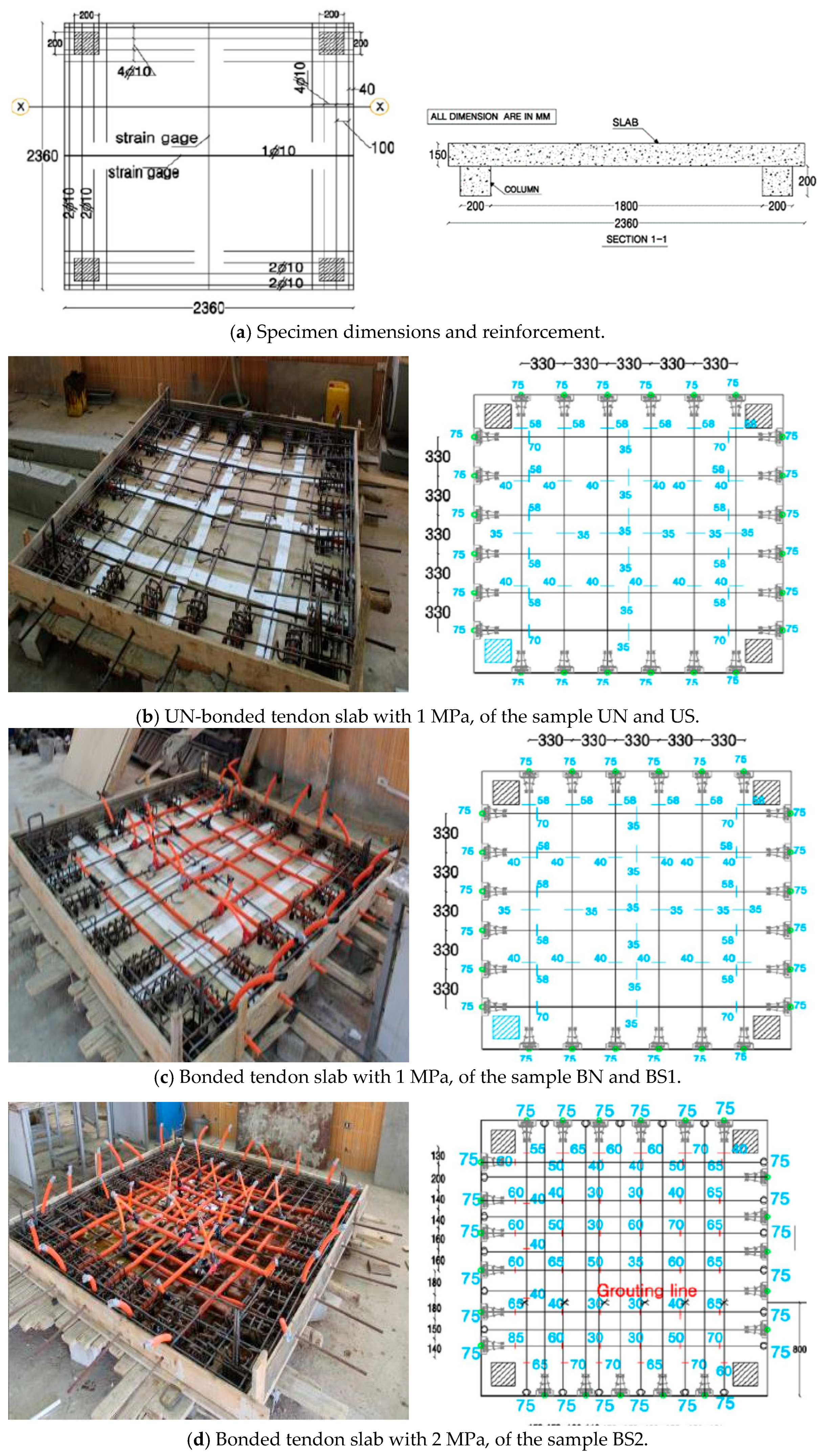
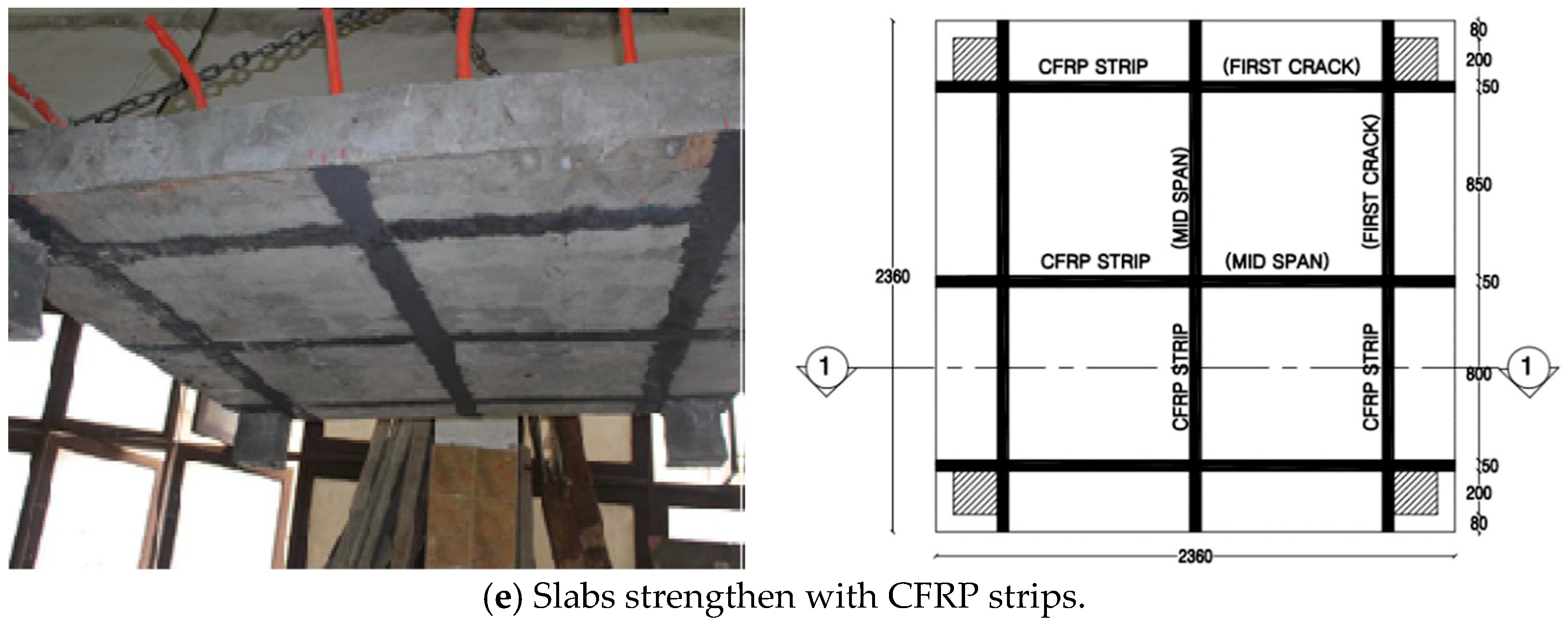
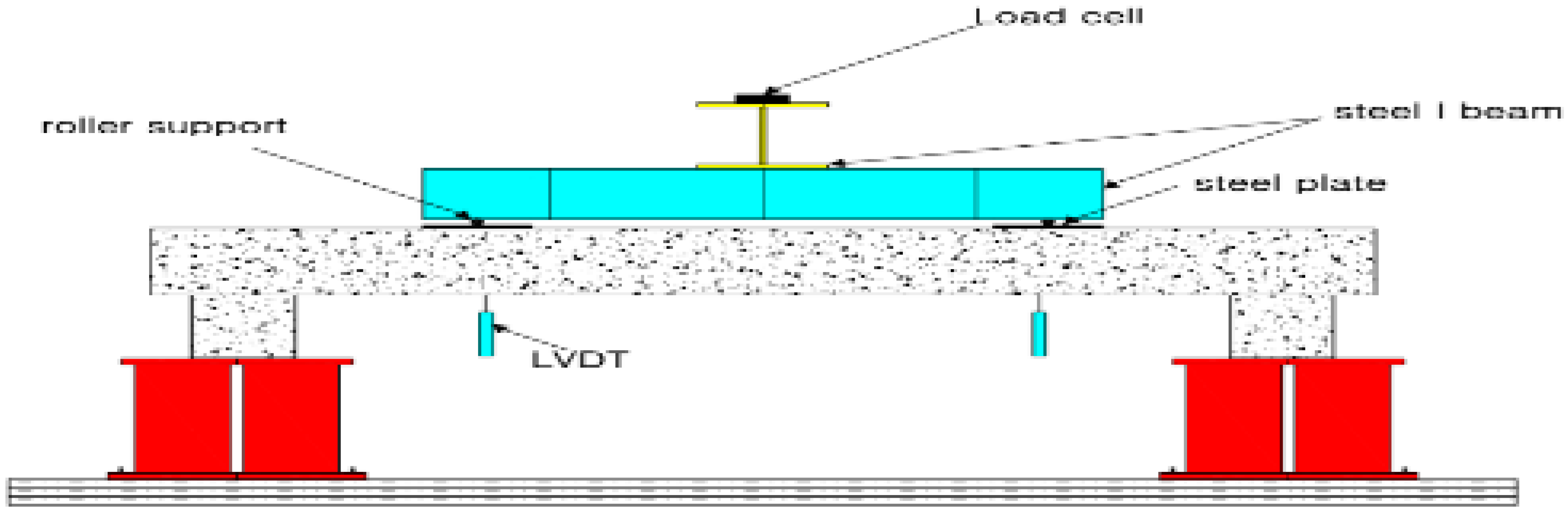
3. Experimental Procedure
4. ANSYS Finite Element Model
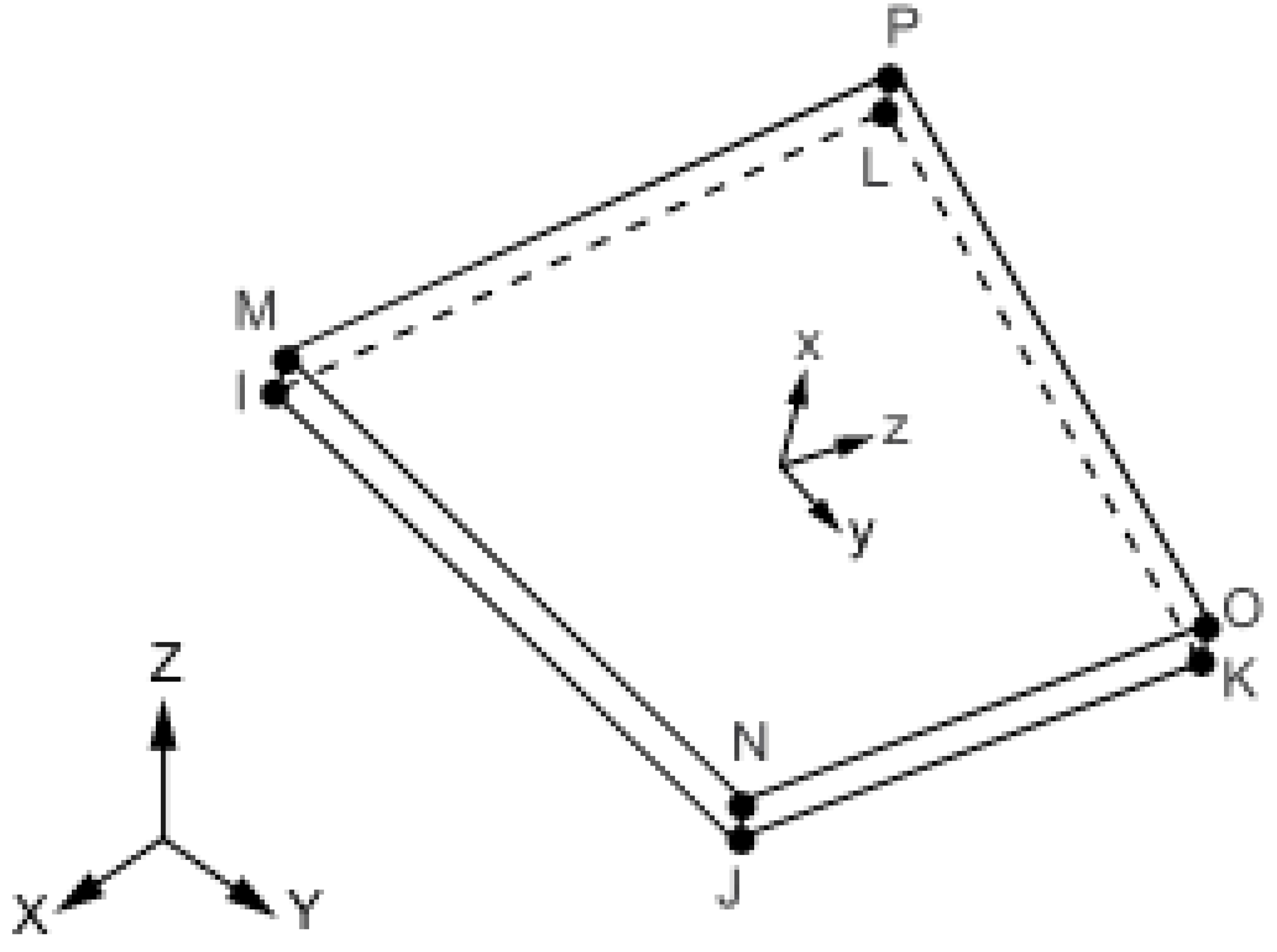
4.1. Main Elements Material and Modeling
- A.
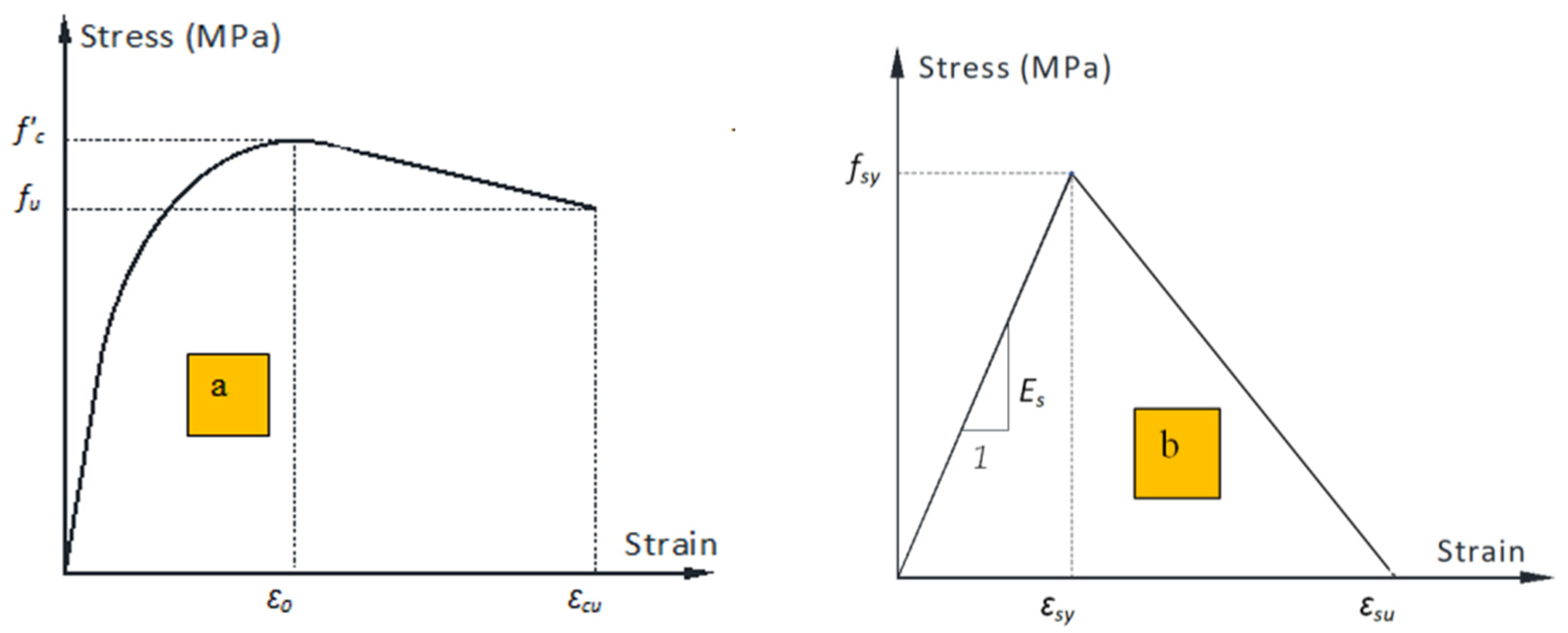
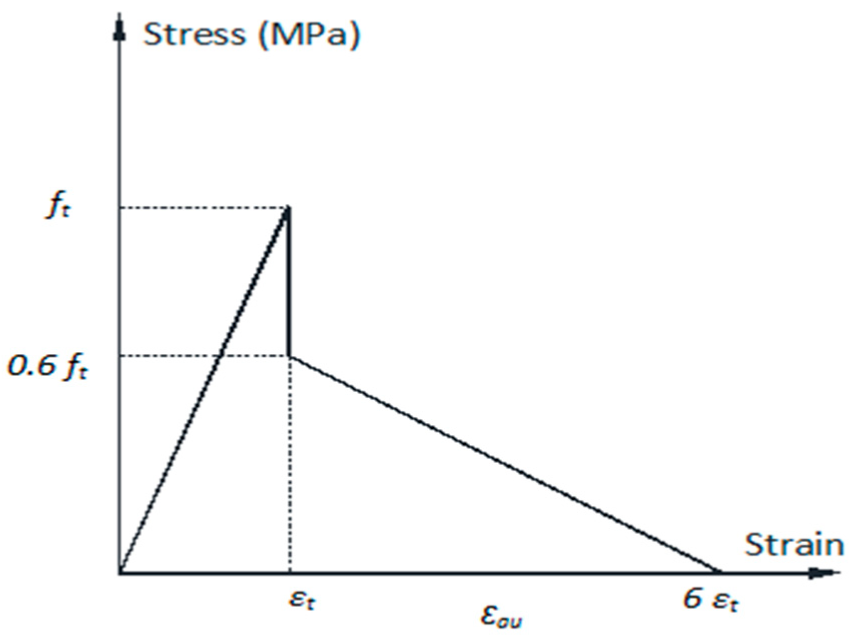
- Concrete
- B.
- Steel Reinforcement and Plates
- C.
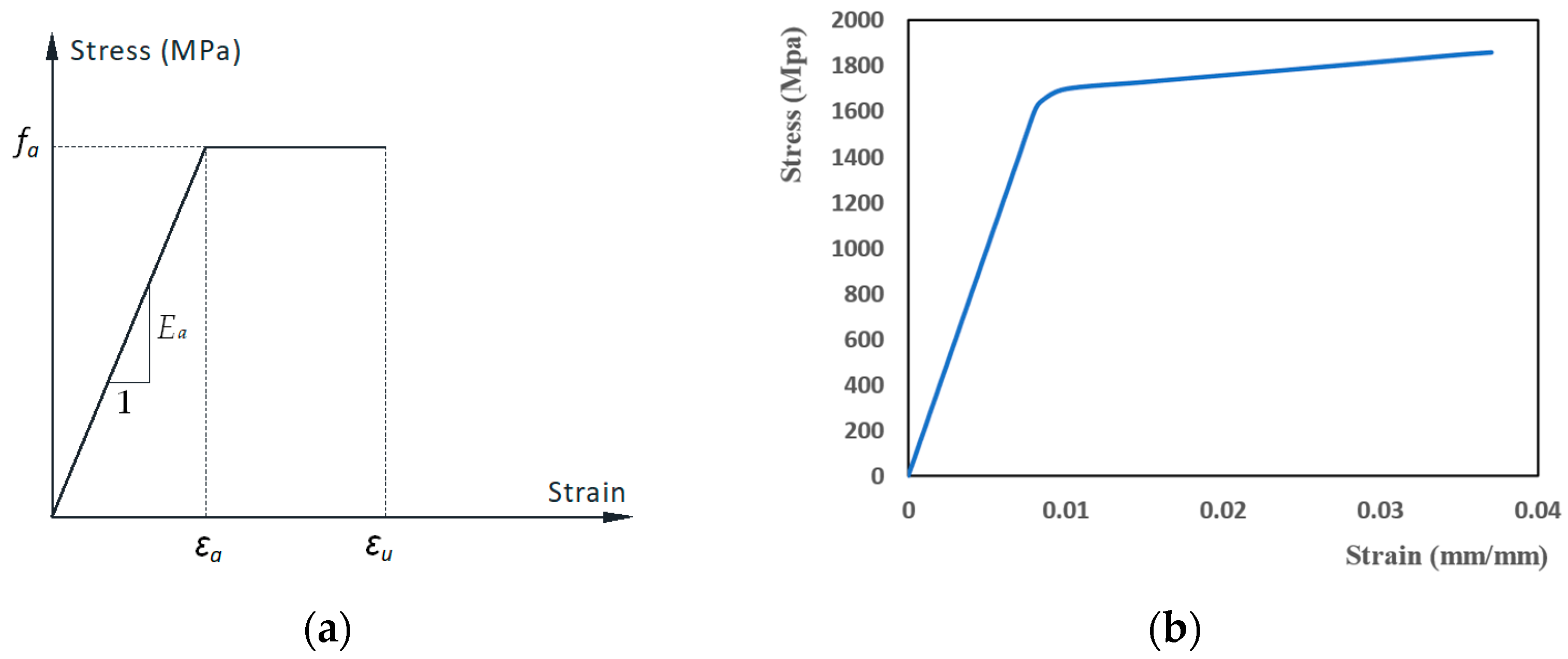
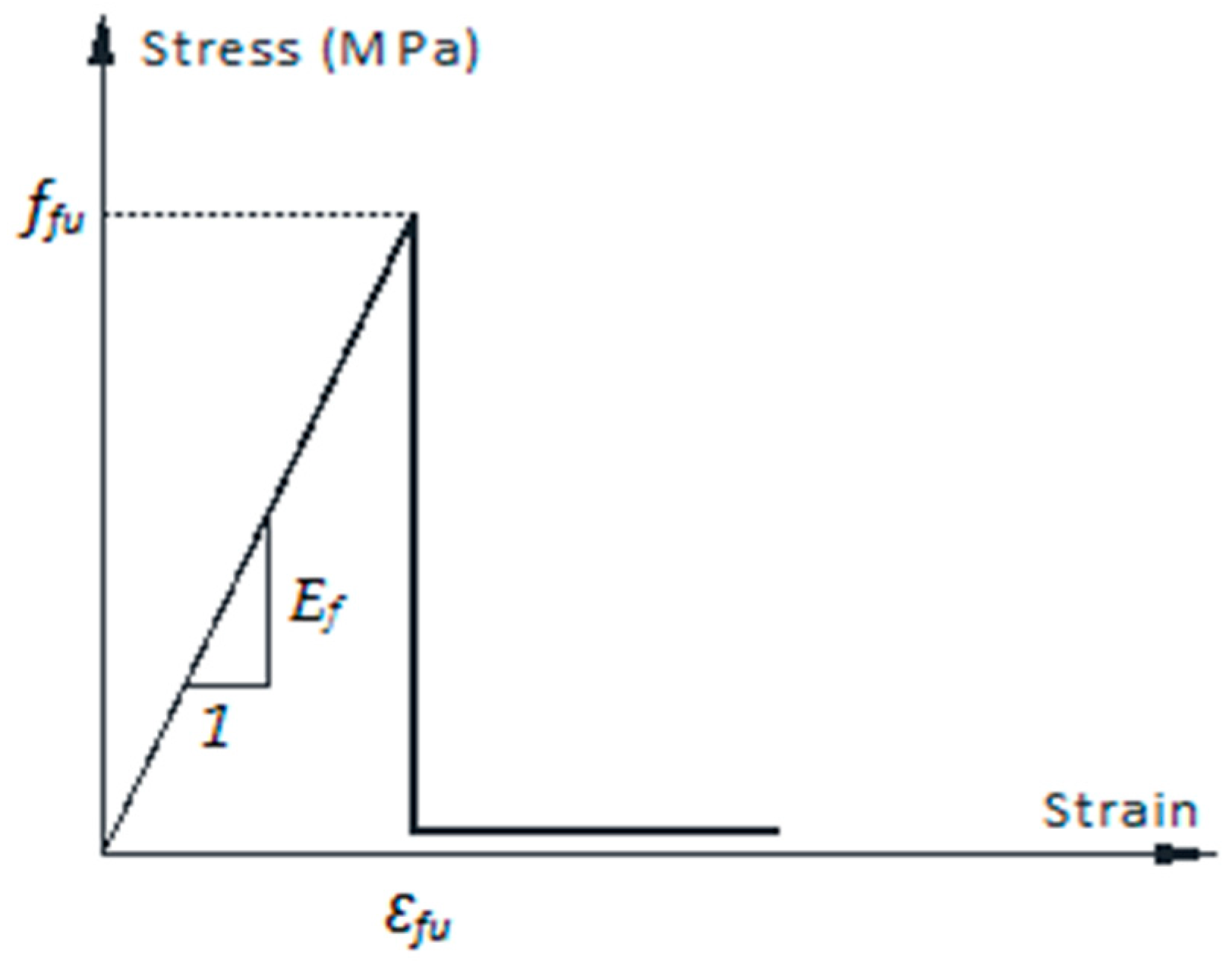
- CFRP Laminates and Epoxy Layers
- D.
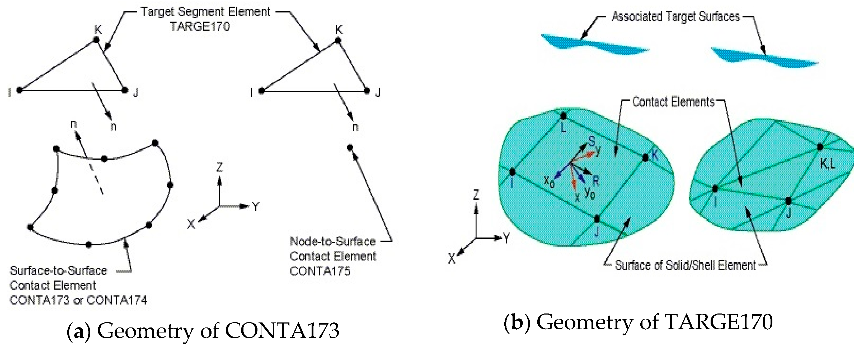
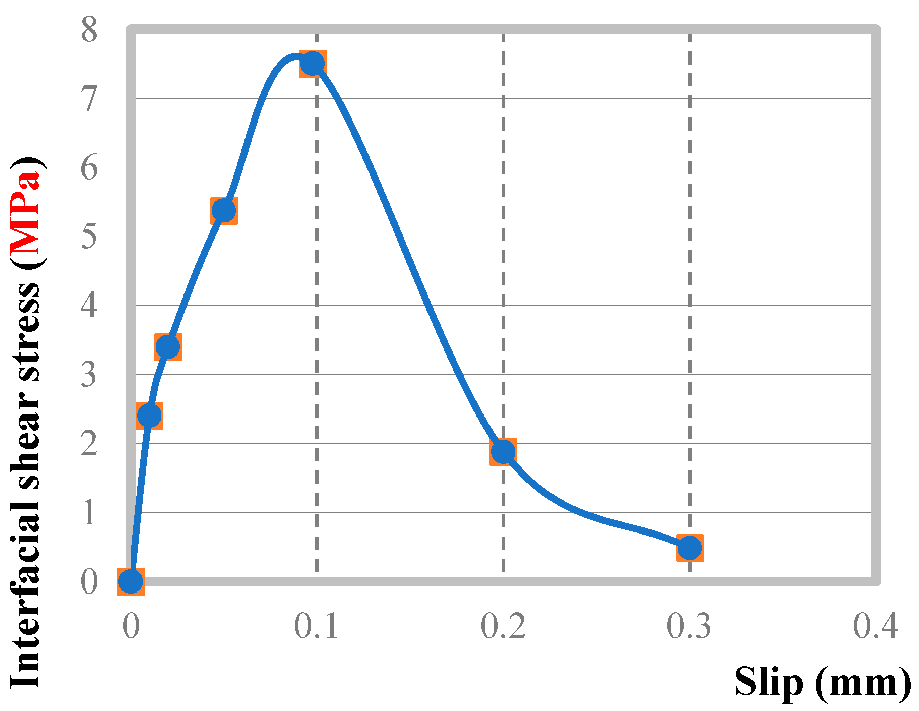
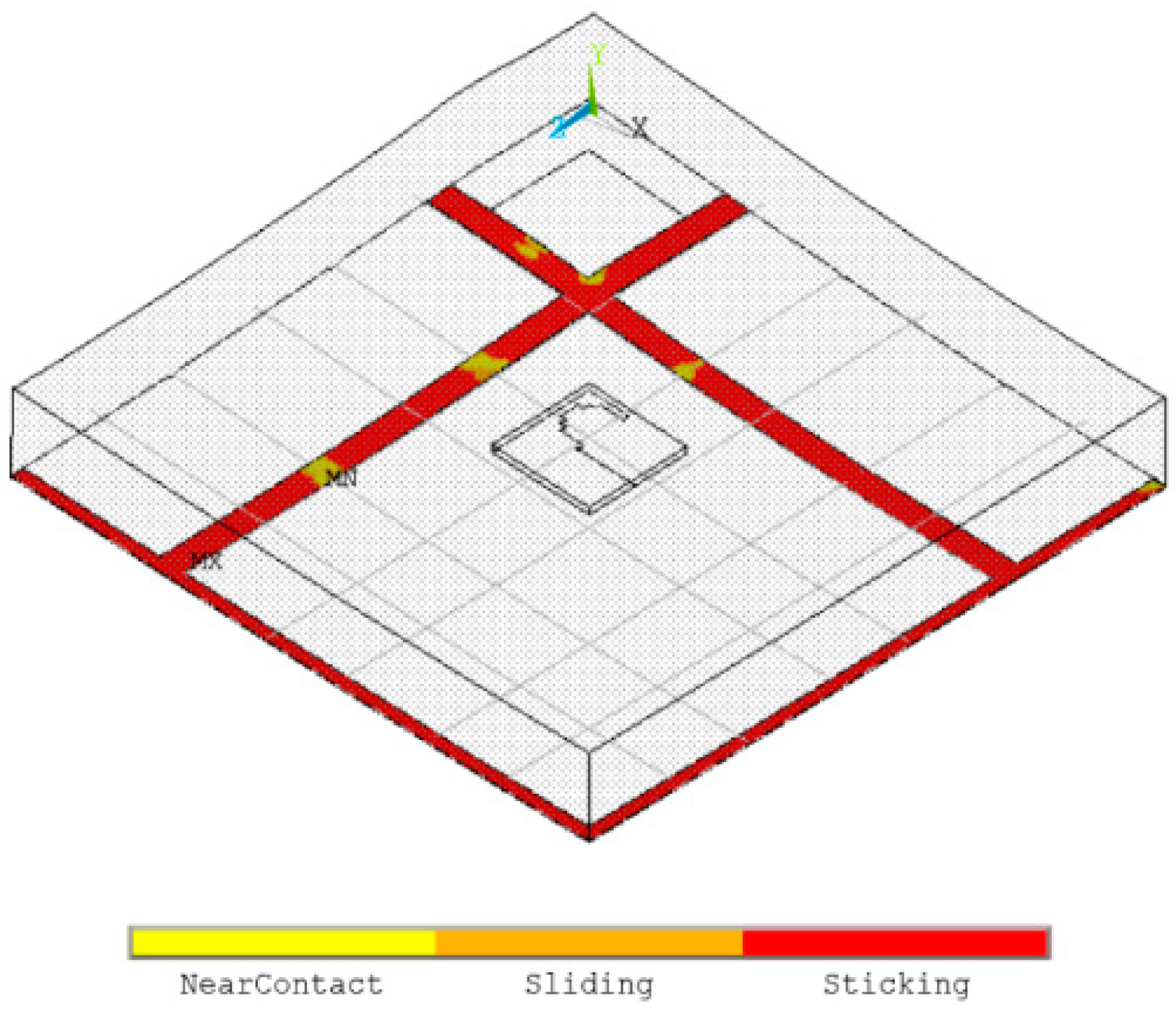
- Epoxy/Concrete and Epoxy/CFRP Interfaces
- E.
- CFRP Slippage
- F.
- Bonded and Unbonded Cable Modeling
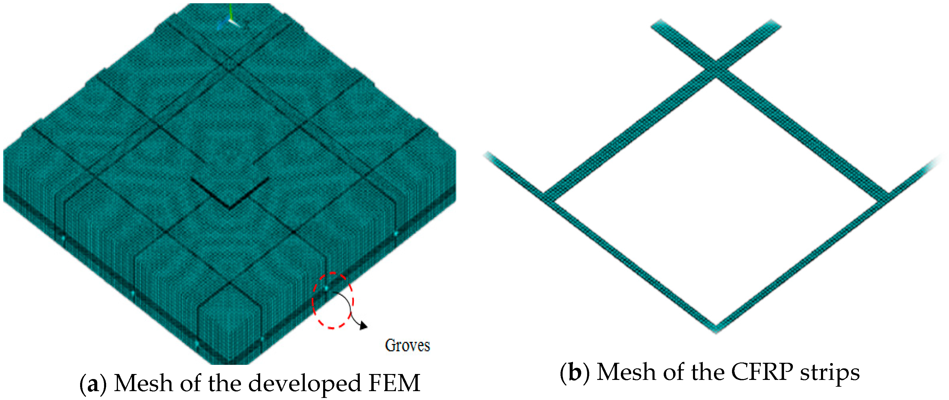
4.2. FEM Meshing
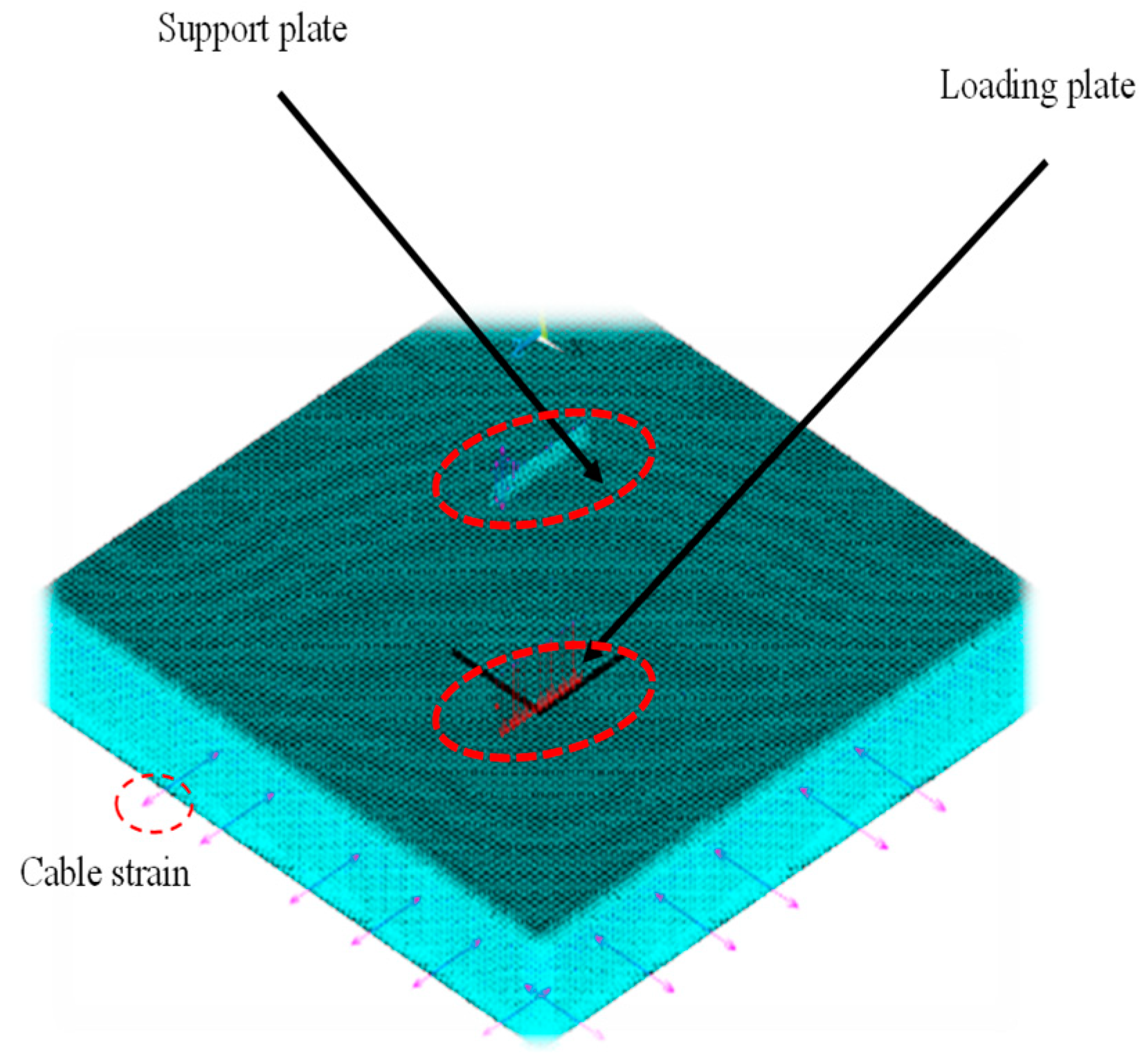
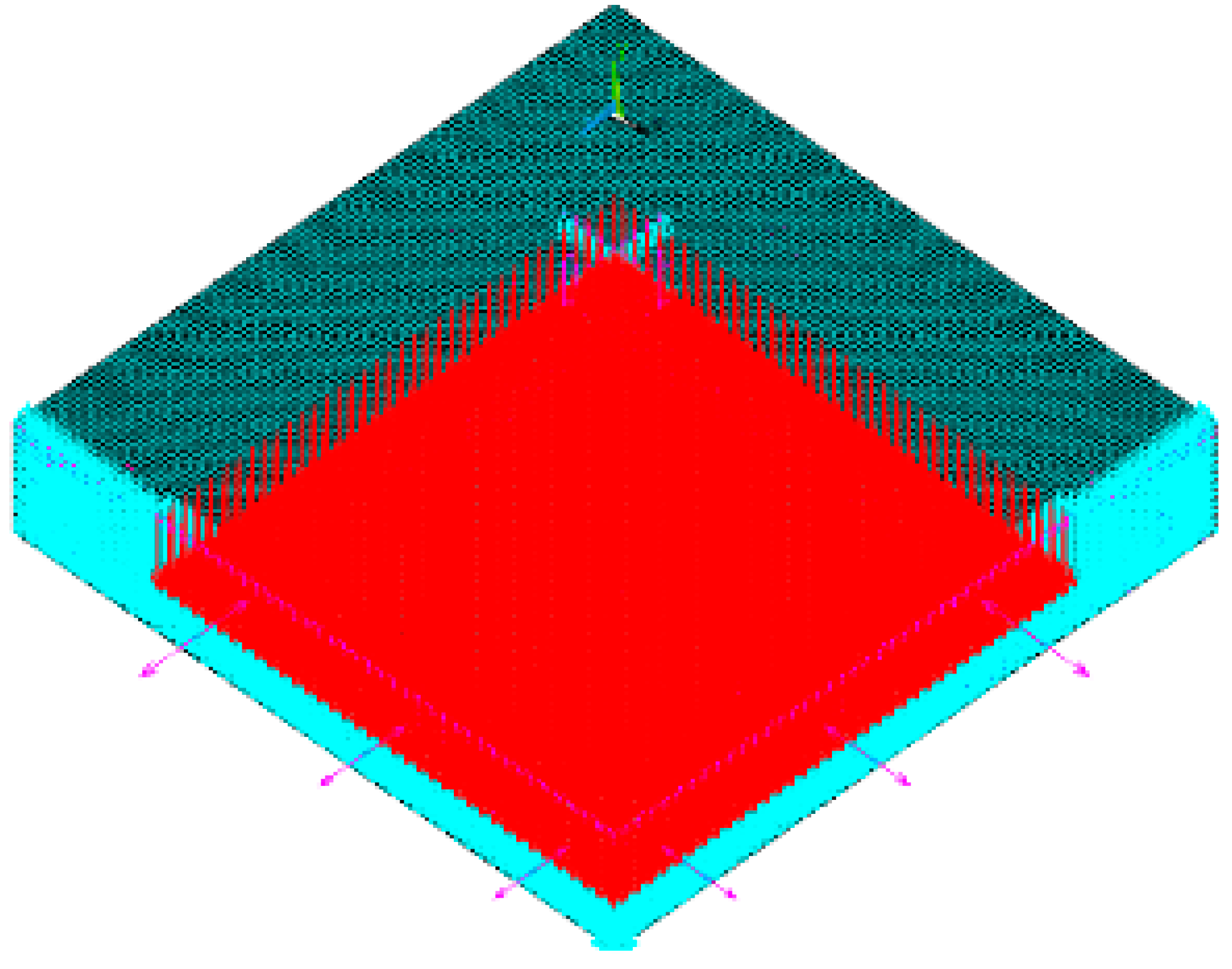
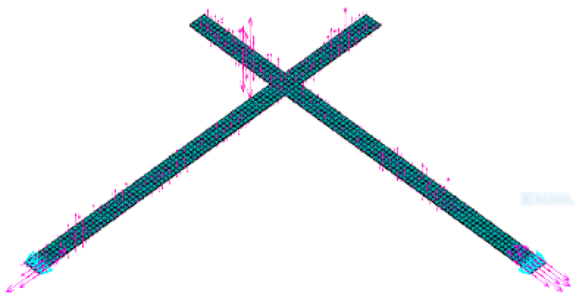
4.3. Loading and Boundary Conditions
4.4. Stepped Analysis
4.5. Model Calibration and Validation
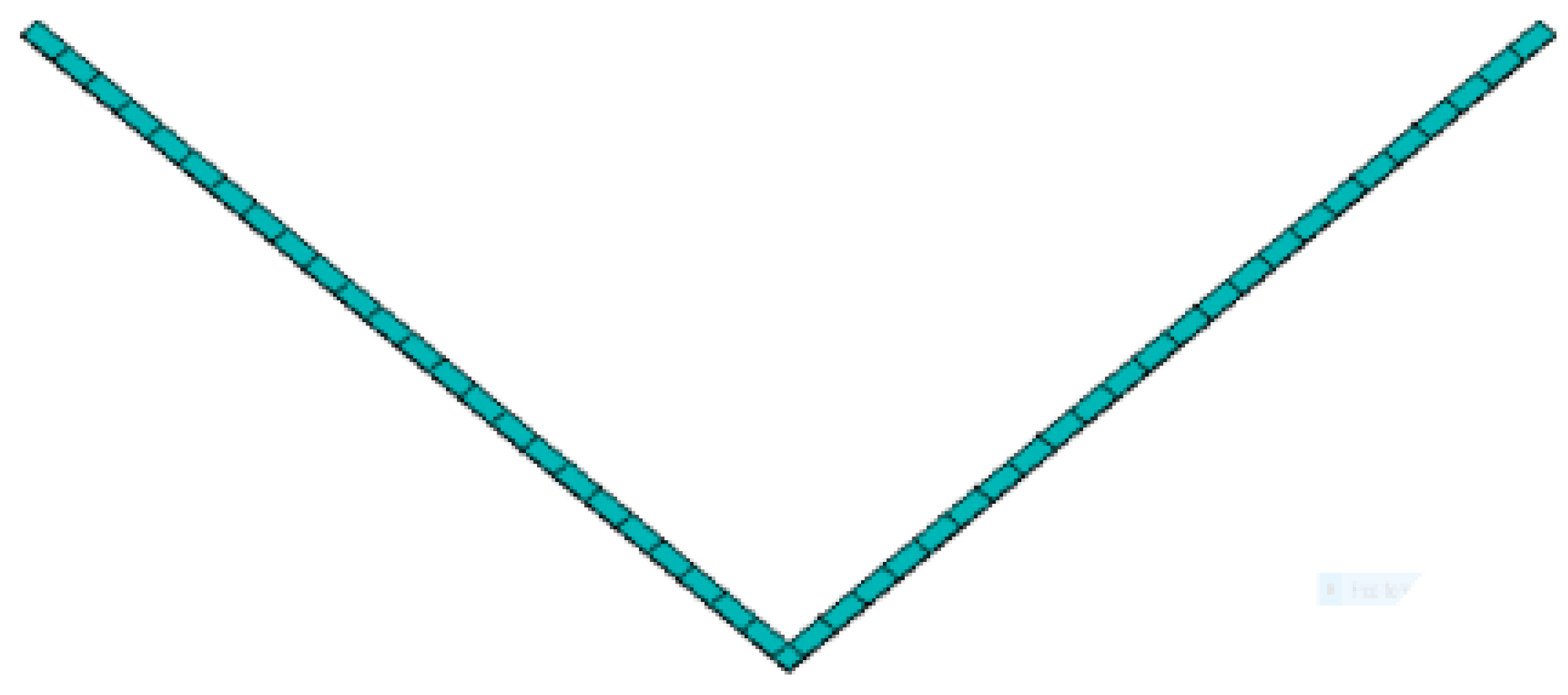
- (A)
- Comparison of Camber
- (B)
- Applying of Initial Strain of Tendons
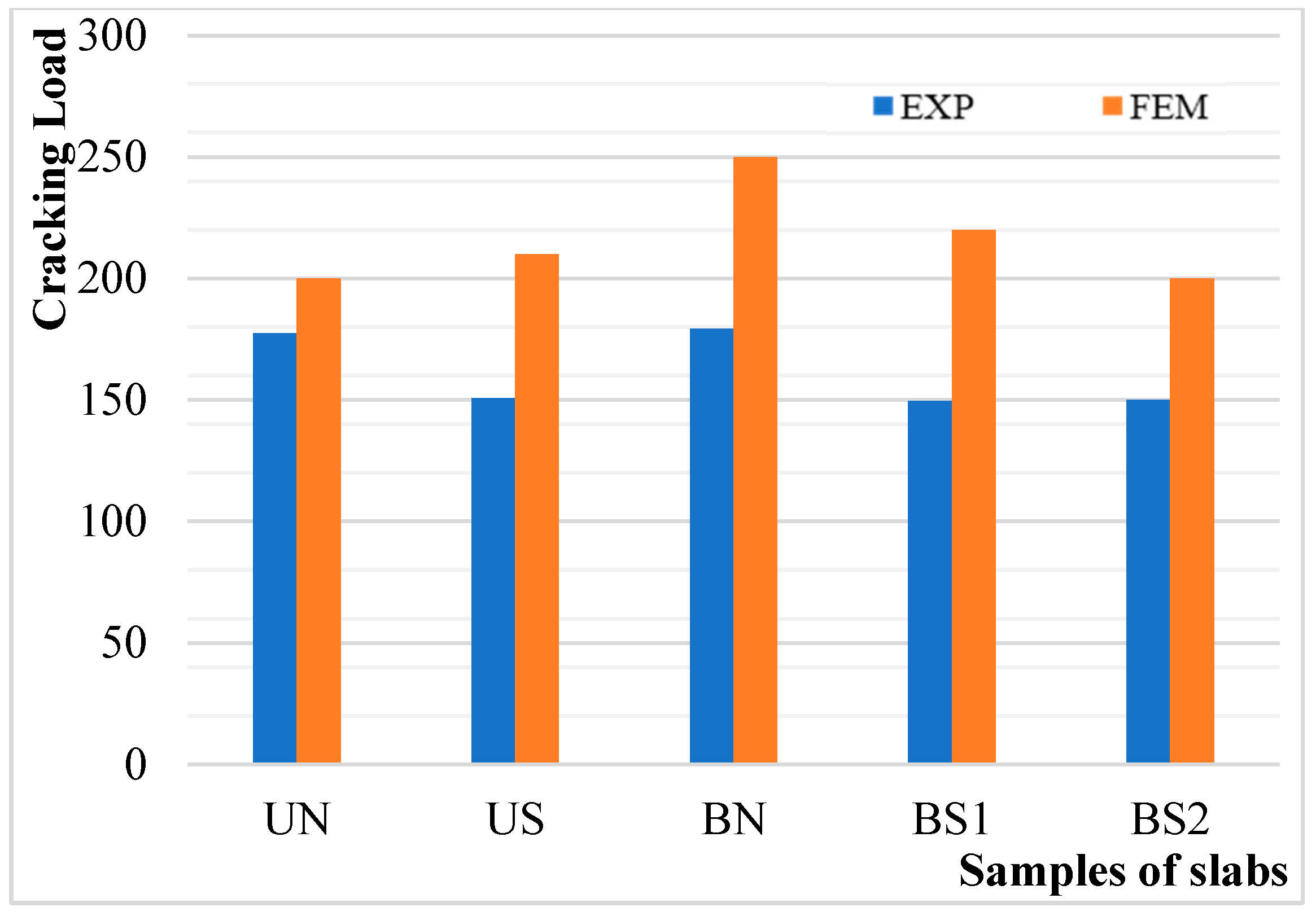
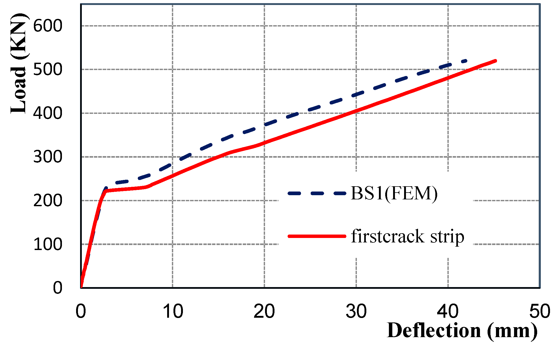
4.6. First Crack Monitoring
5. Results and Discussion
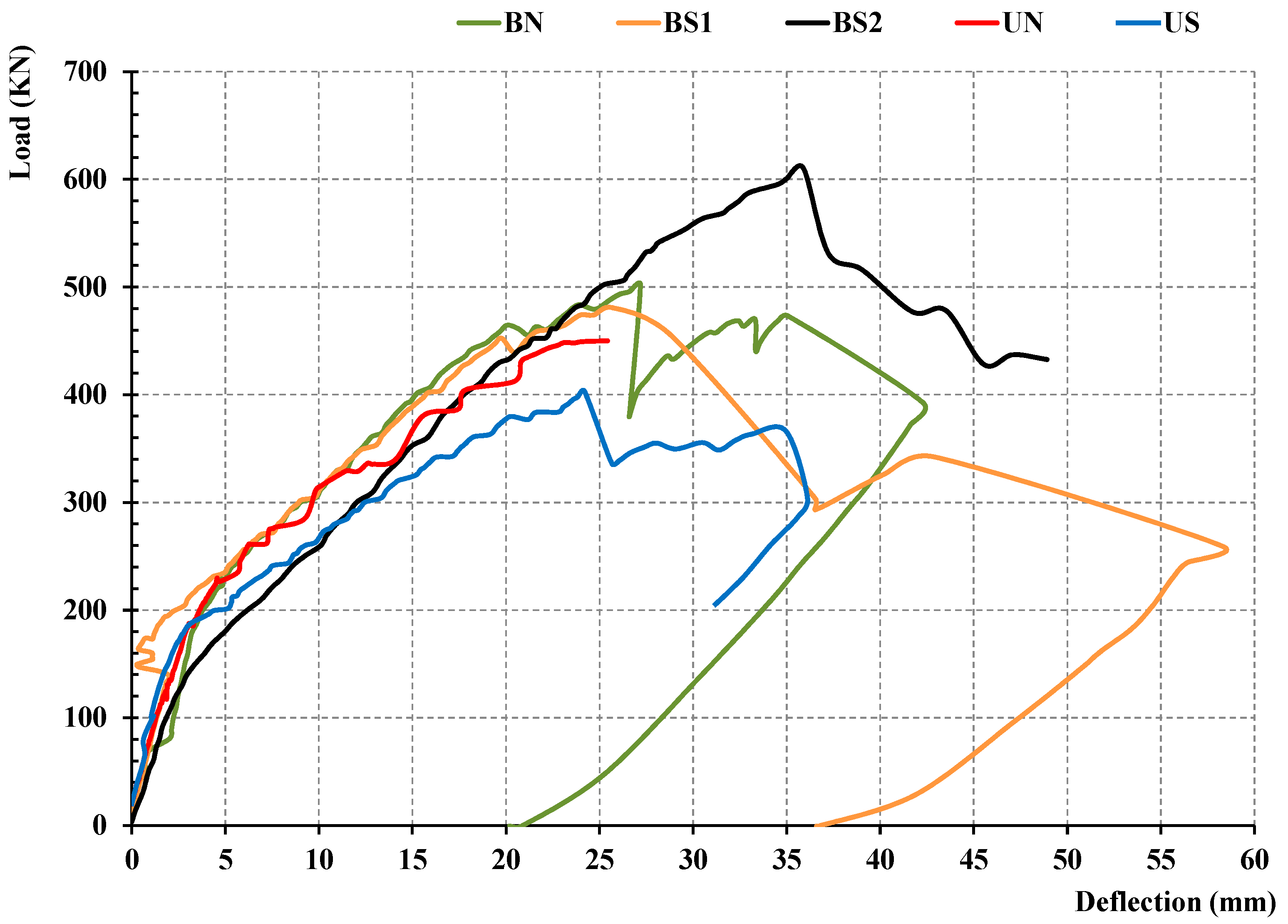
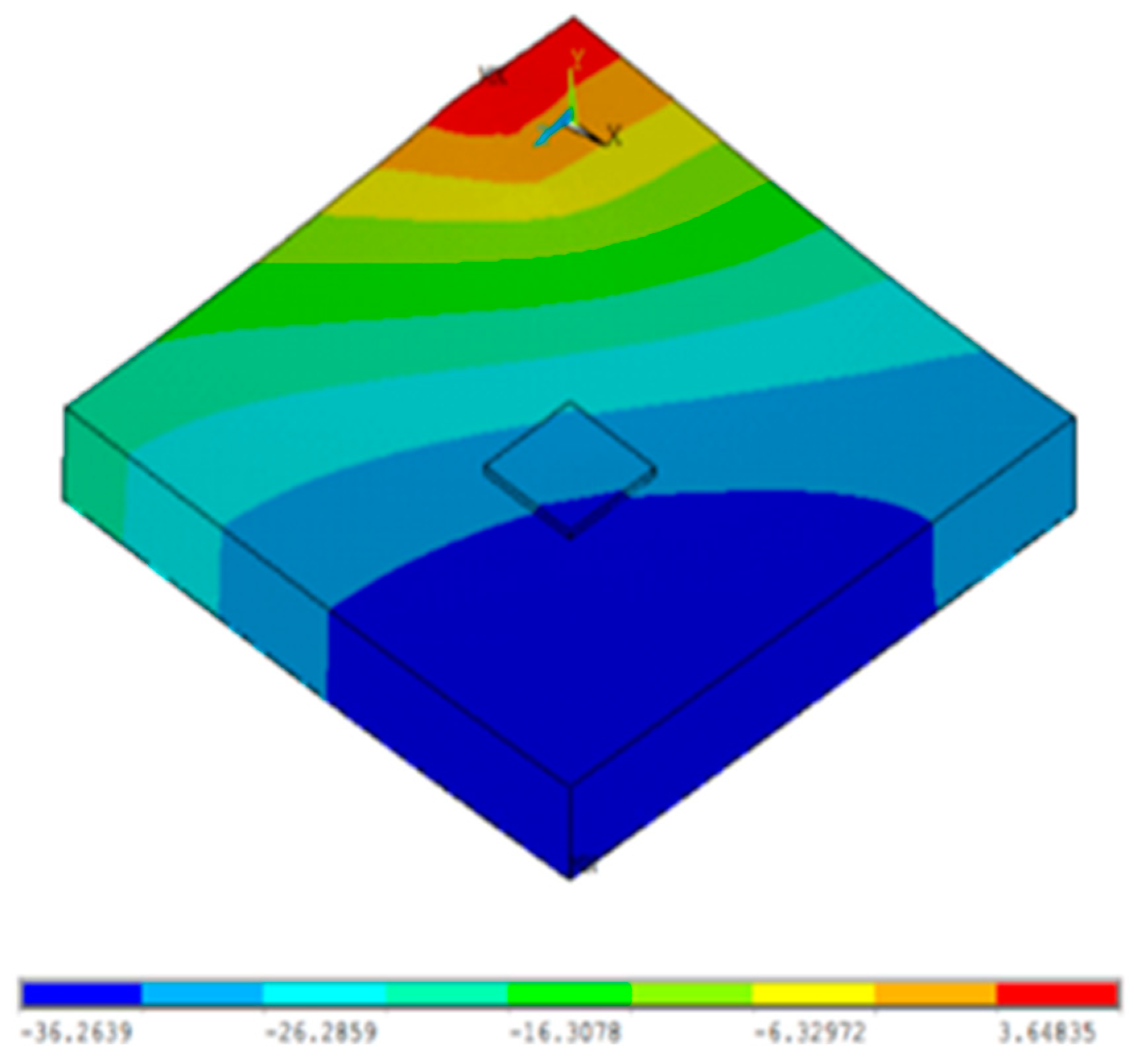
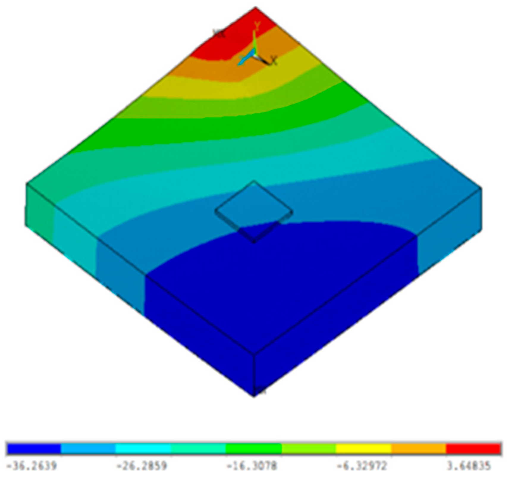
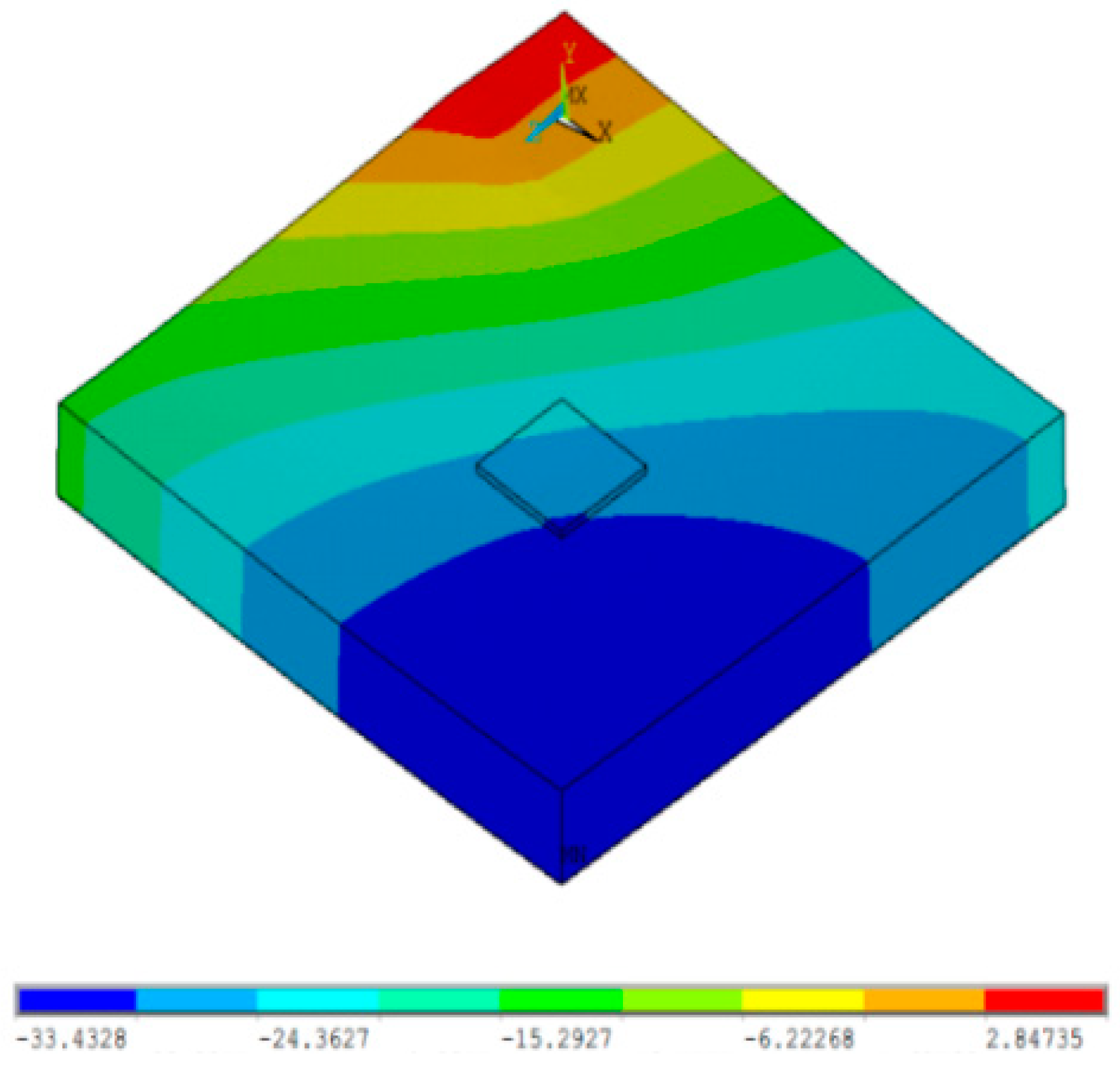
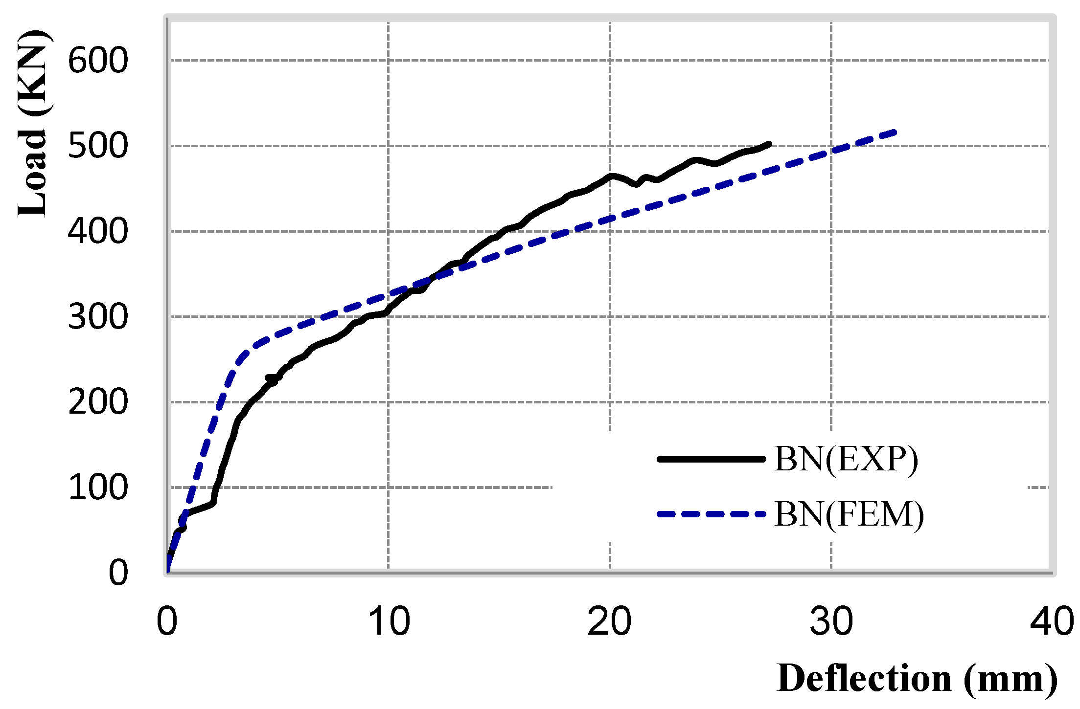
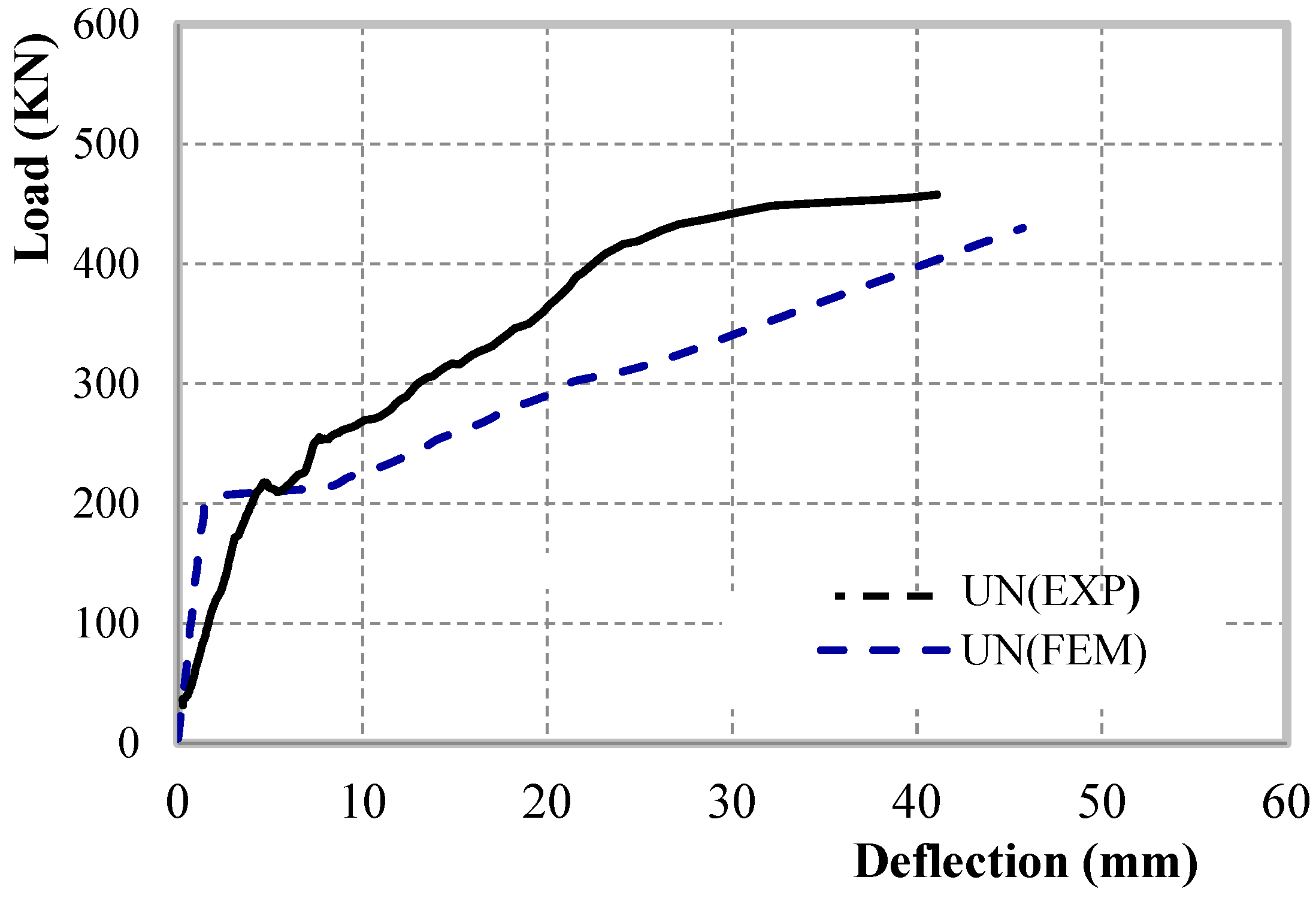
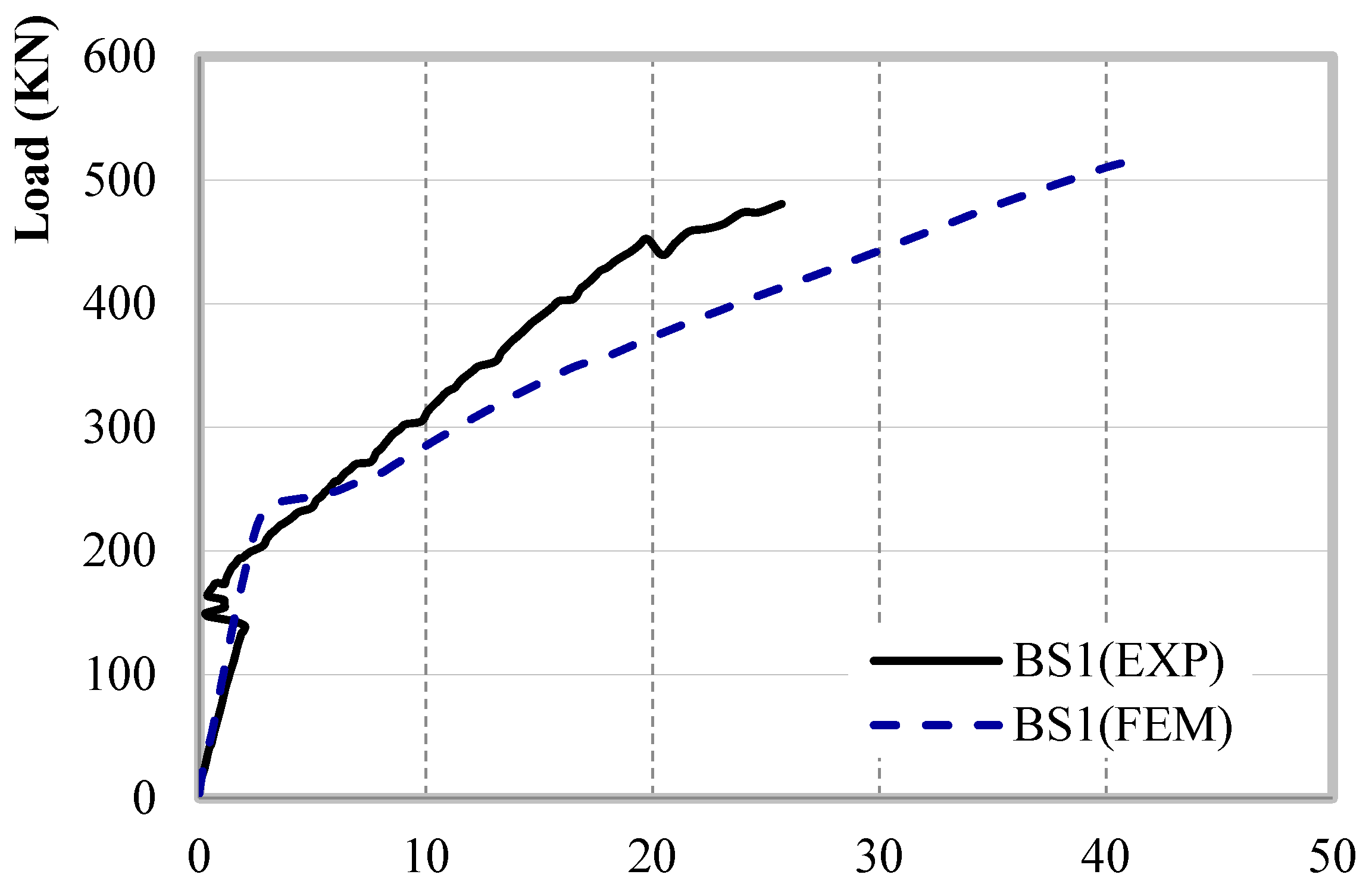
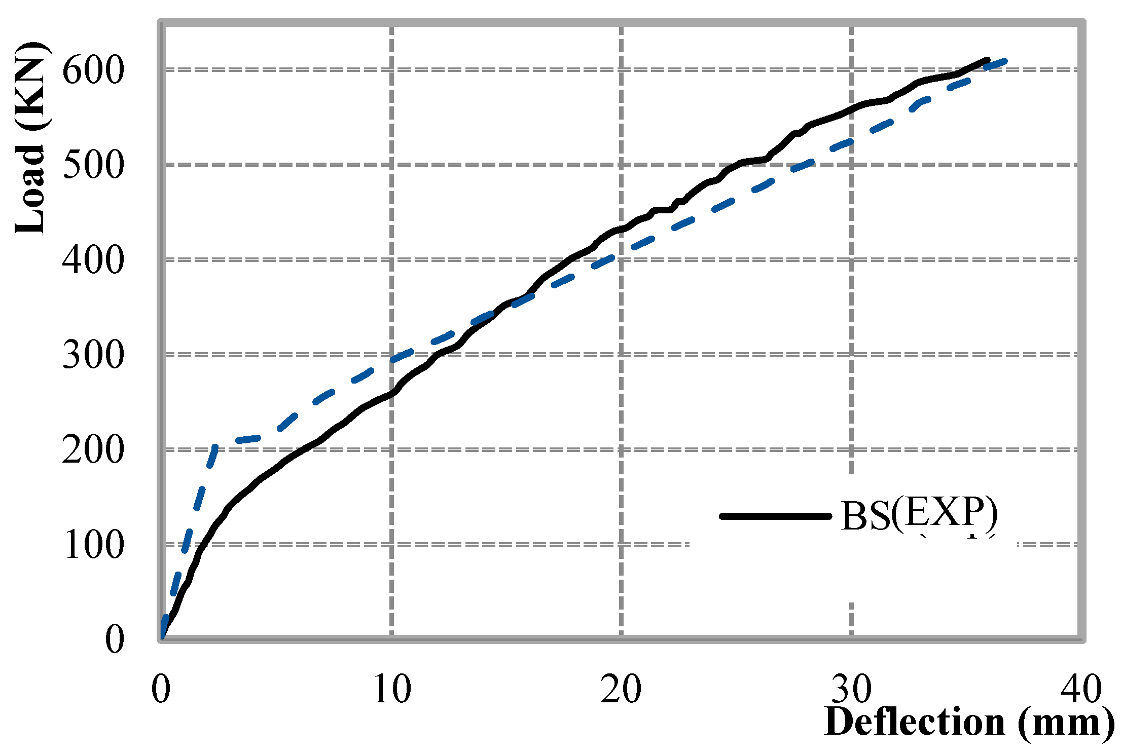
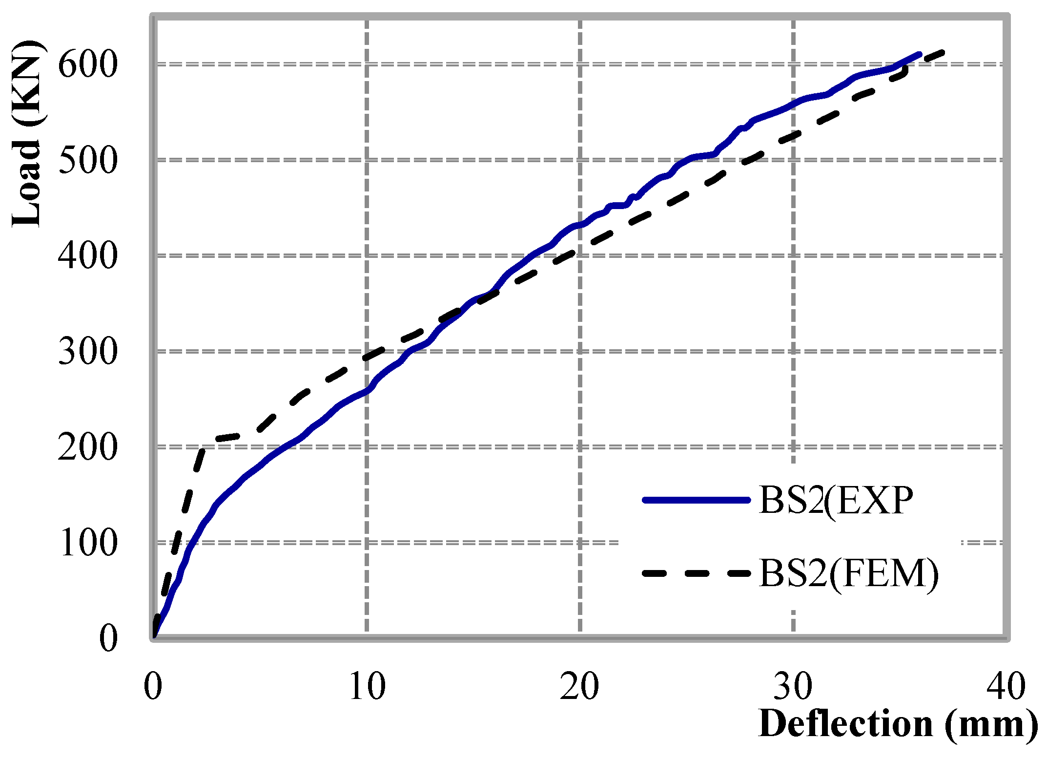
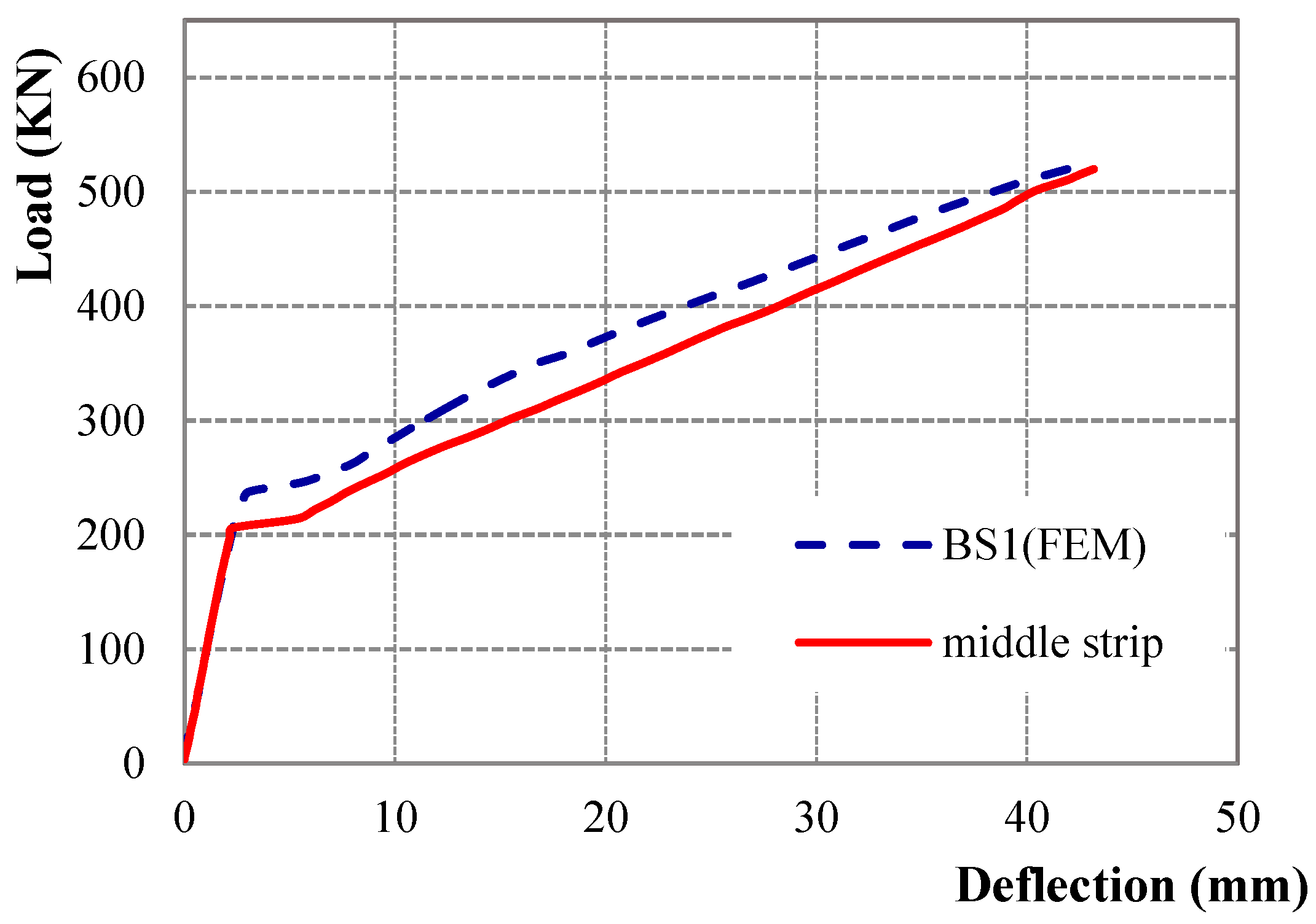
5.1. Load Deflection Behavior
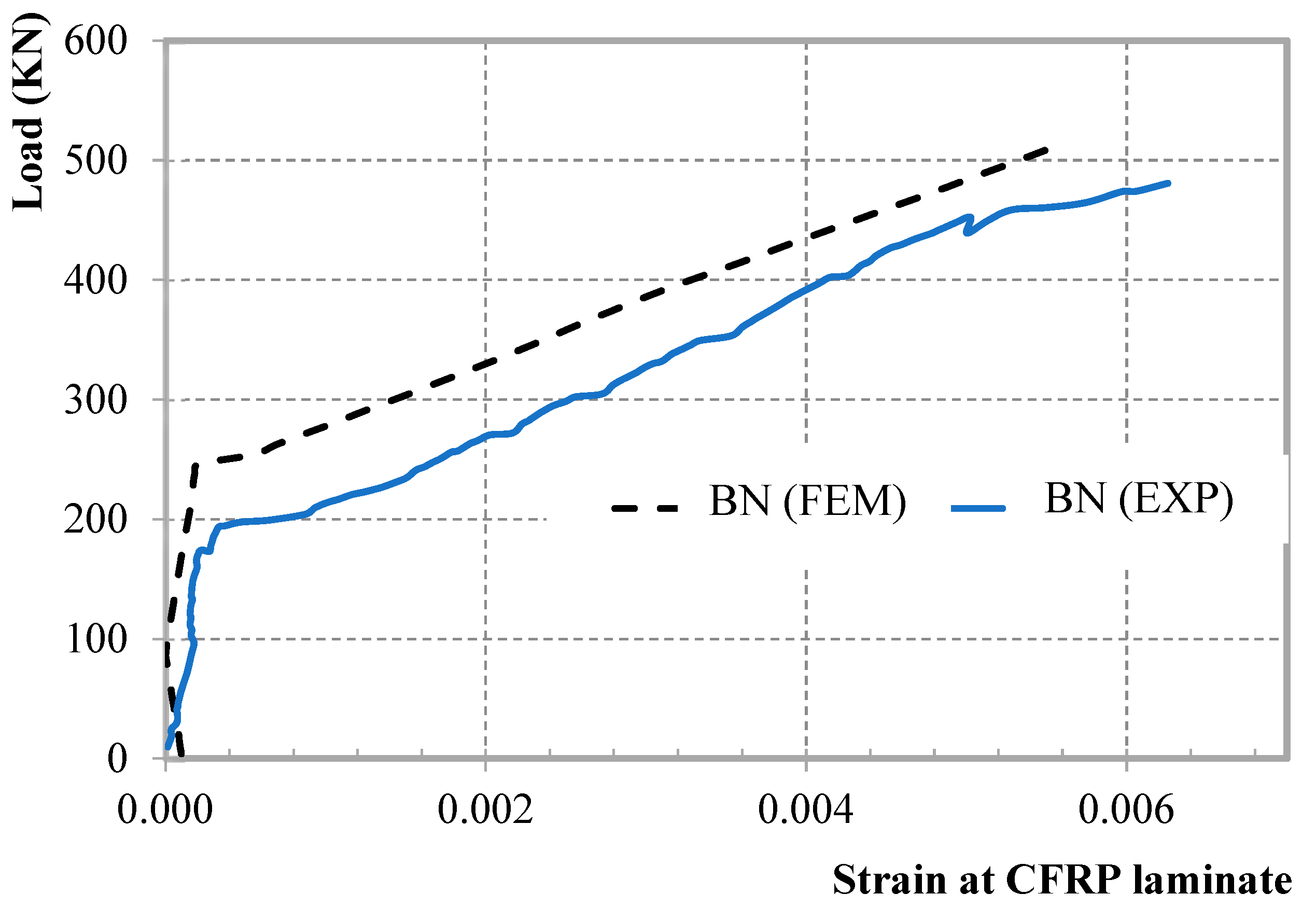
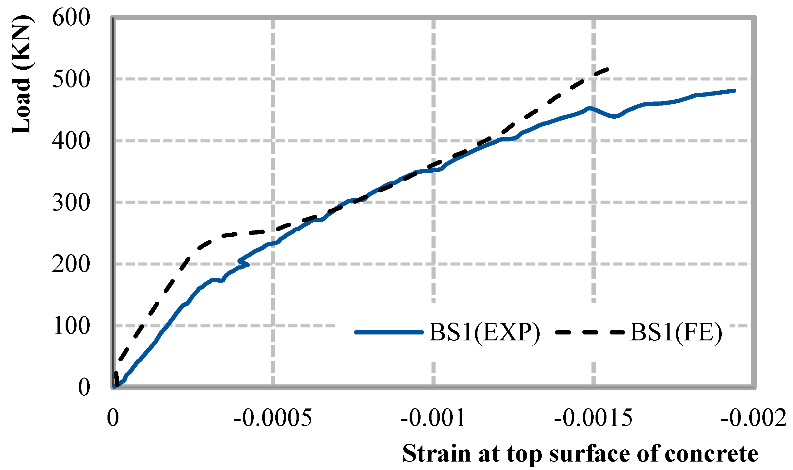
5.2. Concrete and CFRP Strain Behavior
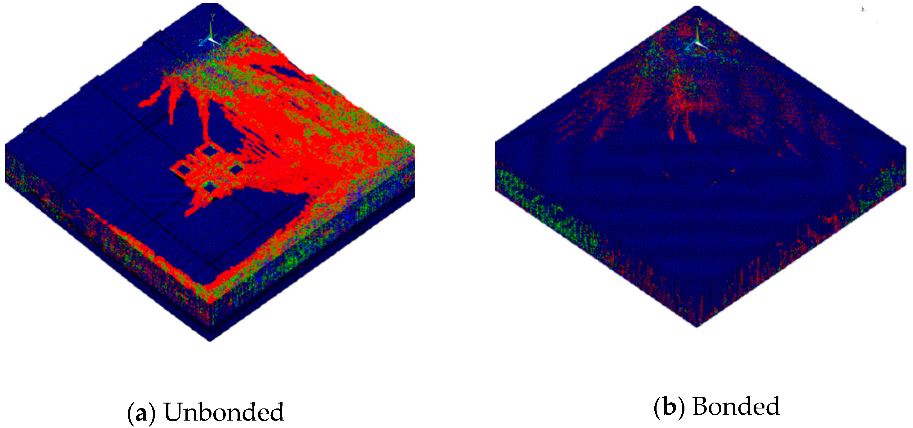
5.3. Failure Modes
- Concrete crushing; when the strain of concrete reaches 0.002,
- Tendon cut; due to reaching its ultimate capacity (not occurring here),
- CFRP debonding; concrete cover or CFRP laminate separation at the surface plane.
6. Parametric Study
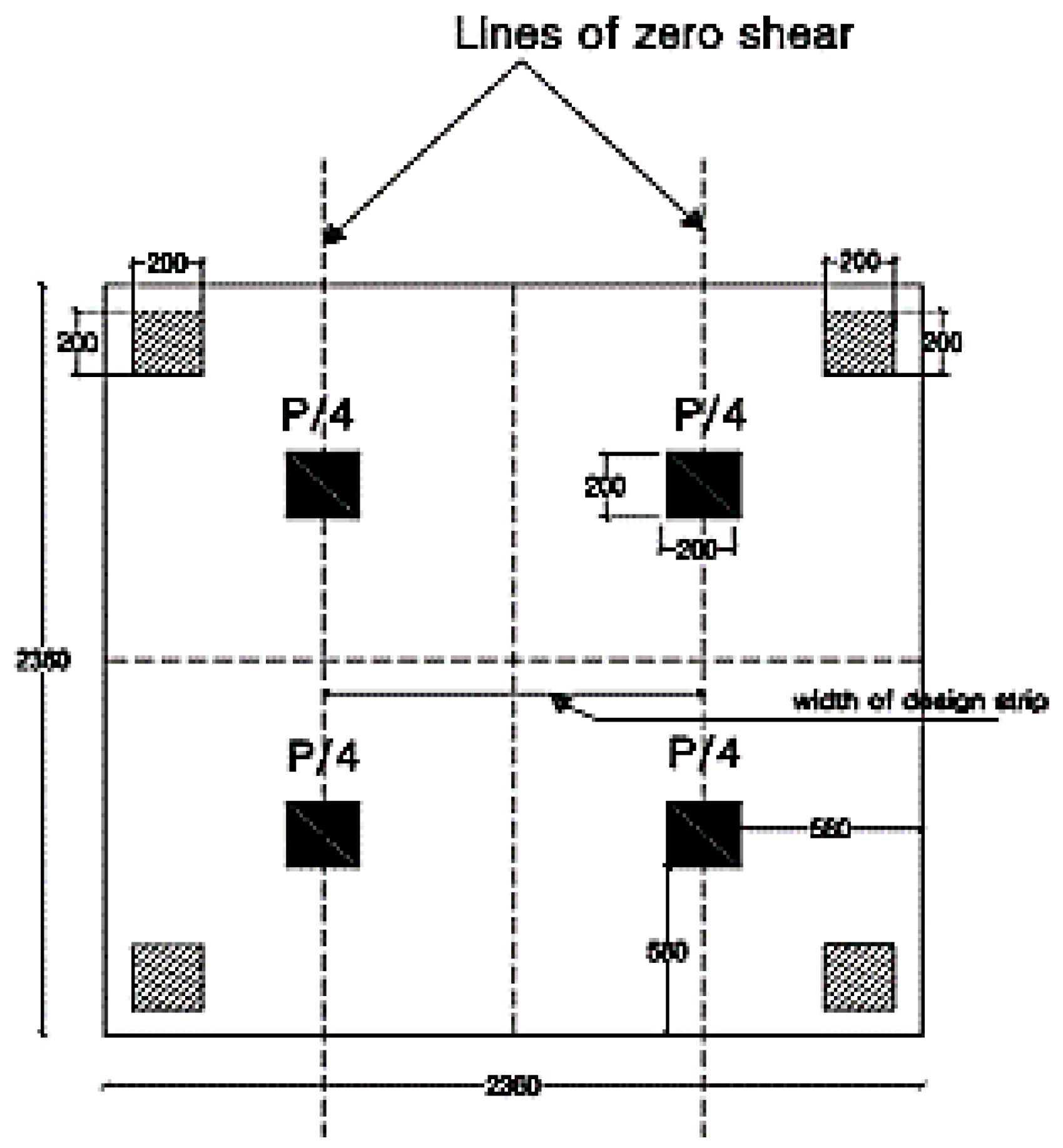
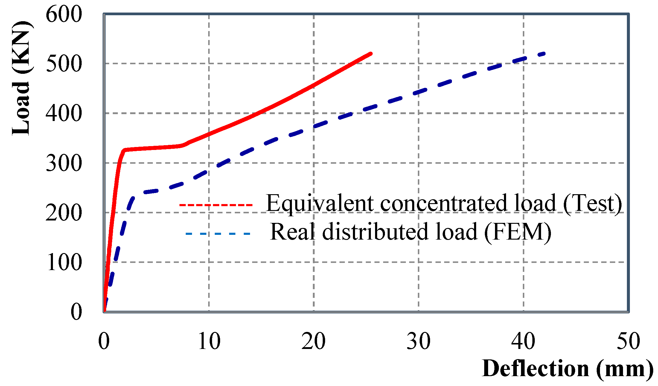
6.1. Real Load Simulation
6.2. Different Arrangements of CFRP Laminates
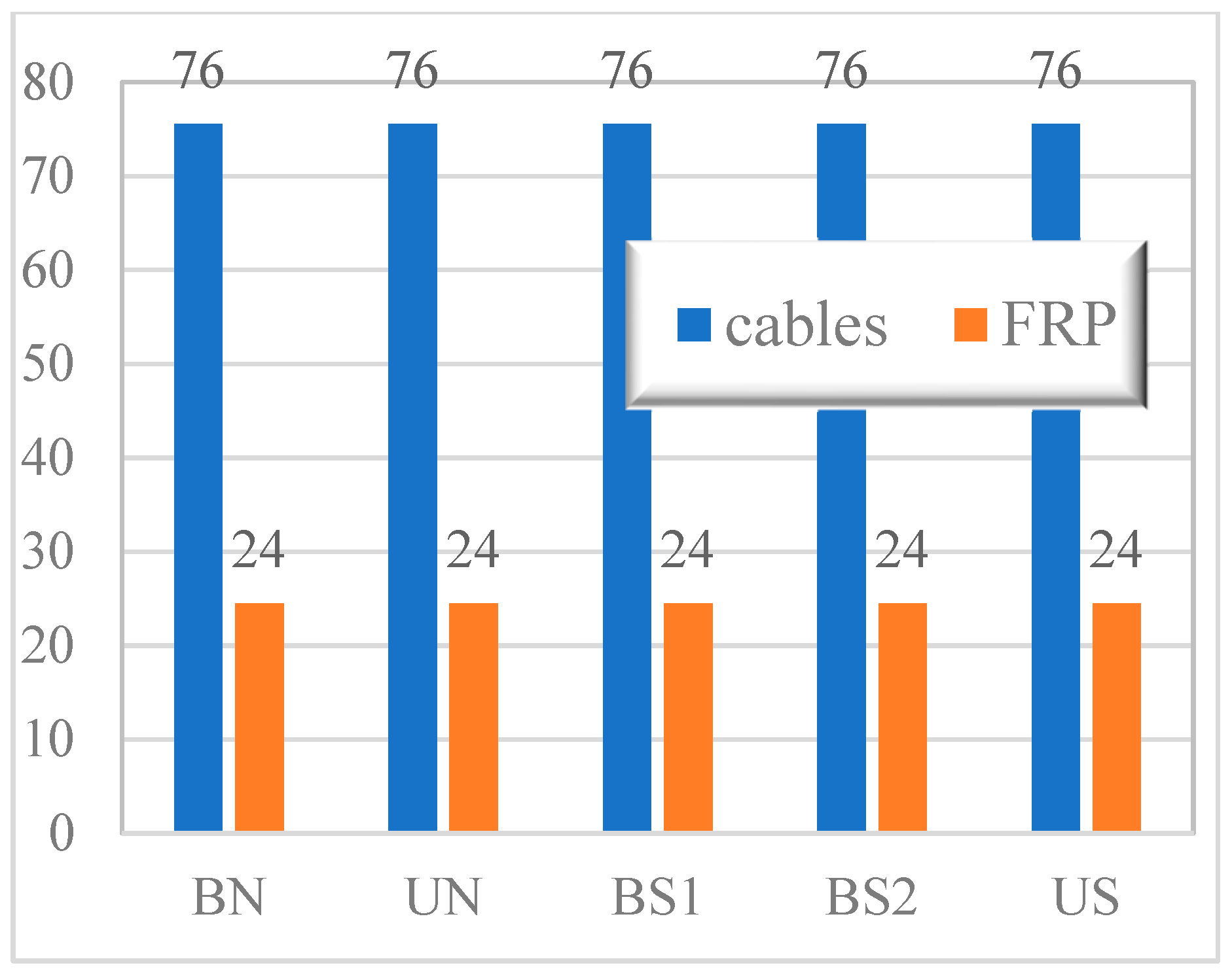
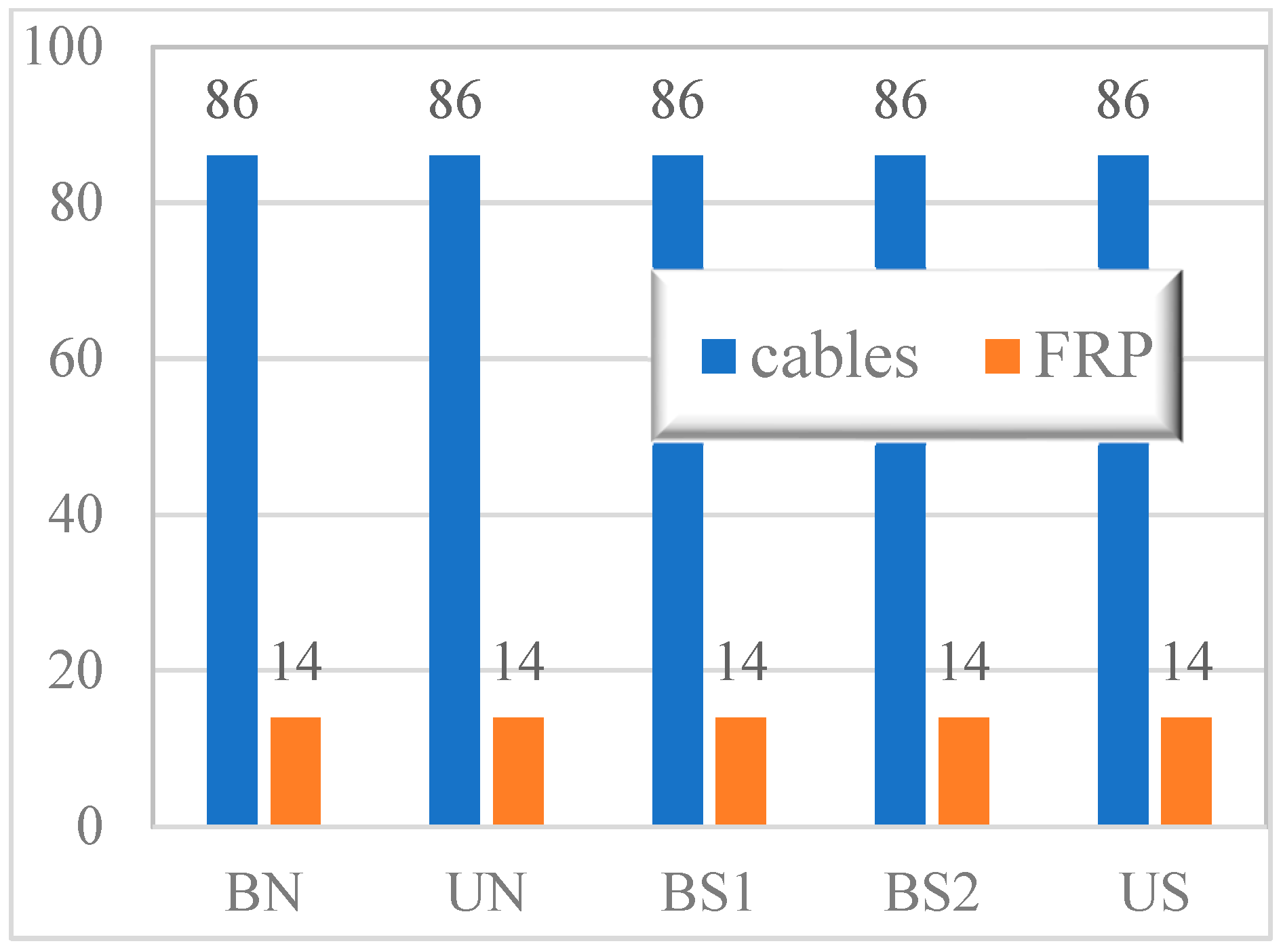
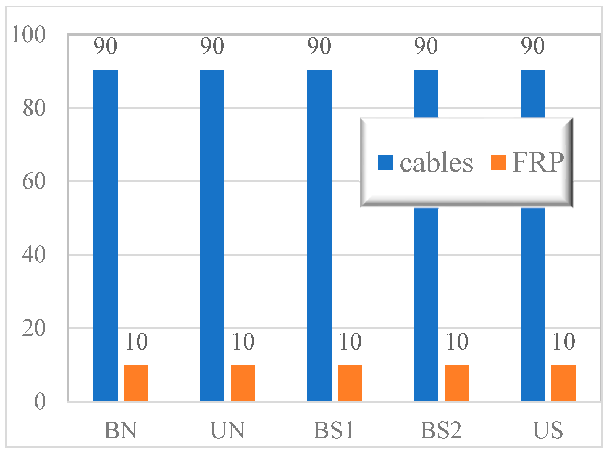
6.3. PT to CFRP Strength Contribution
7. Conclusions
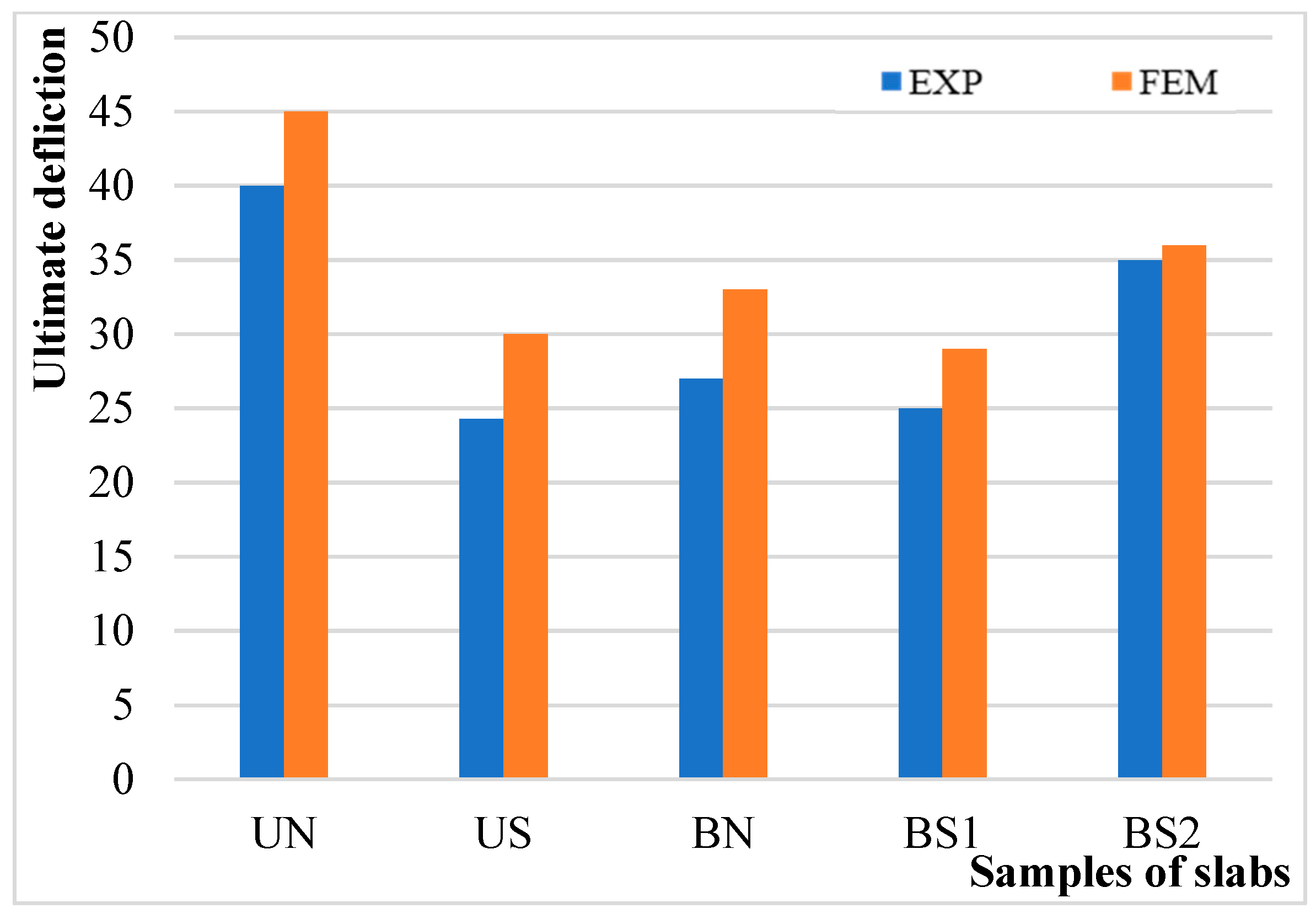
- The FEM simulation showed great agreement with experimental results. The ratio between the experimental and FEM results of the first cracking load varied from 0.7 to 0.9, whereas the results of the ultimate load varied from 0.8 to 1.1 and the ultimate deflections varied from 0.8 to 1.
- At different loading levels, there is a good correlation between FEM results and experimental results for CFRP strains either for the final debonding stage or for the locations of slippage.
- From both FEM and experiments, it was concluded that the failure modes of the tested slabs were concrete crushing, CFRP rupture, and/or CFRP debonding.
- Performance of the fully prestressed post-tensioned two-way slabs pre-strengthened with CFRP laminates have better performance in bonded rather than unbonded slabs.
- Strengthening using CFRP materials is extremely effective in increasing the ductility index of both bonded and unbonded PT concrete slabs. Ductility increased by 62.18% and 59.87%, respectively, when compared with the control samples.
- Real load simulation rather than test-equivalent criteria is considered a major and sensitive factor that has to be carefully represented in either experimental or numerical simulations to reflect reliable results.
- In selecting an optimized scheme for strengthening PT slabs, it is noted that using laminates adjacent to columns is more efficient than in other slab locations.
- CFRP strength contribution to PT cabling is very considerable in slabs with low PT reinforcement ratios, whereas it is not effective in slabs with larger PT ratios.
- Finally, the results that were obtained using a numerical FEM model with the ANSYS program demonstrated good agreement with experimental results for illustrated slabs.
Author Contributions
Funding
Institutional Review Board Statement
Informed Consent Statement
Data Availability Statement
Acknowledgments
Conflicts of Interest
References
- Al Mohammedi, A.; Murray, C.D.; Dang, C.N.; Hale, W.M. Practical ultra-high-strength concrete for precast concrete applications. PCI J. 2022, 67, 29–52. [Google Scholar] [CrossRef]
- Mante, D.M.; Isbiliroglu, L.; Hofrichter, A.; Barnes, R.W.; Schindler, A.K. Expected compressive strength in precast, prestressed concrete design: Review and discussion of regional practice. PCI J. 2022, 67, 53–70. [Google Scholar] [CrossRef]
- Bhuiyan, I.H.; Amin, A.; Riyad, R.H.; Sadi, R.; Hasan, M.A. Structural analysis of pre-tensioning and post-tensioning concrete with normal concrete beam. In Proceedings of the International Conference on Planning, Architecture & Civil Engineering, Rajshahi, Bangladesh, 9–11 September 2021. [Google Scholar]
- Khalil, A.H.H.; Ashraf, M.; Heniegal, A.; Attia, M.M. Behavior of post-tensioned fibrous lightweight concrete beams made of natural pumice. In Proceedings of the 2nd International Conference, Sustainable Construction and Project Management Sustainable Infrastructure and Transportation for Future Cities, Aswan, Egypt, 16–18 December 2018. [Google Scholar]
- Cho, A.S.; Kang TH, K. Computer-based design optimization of post-tensioned anchor for single-strand. Adv. Comput. Des. 2021, 6, 339–360. [Google Scholar] [CrossRef]
- Abdelhalim, J.O.; Sayed-Ahmed, E.Y. Testing post tensioned slabs with bonded and unbonded tendons. In Proceedings of the International Conference on Civil, Structural and Transportation Engineering, Virtual, 17–19 May 2021. [Google Scholar] [CrossRef]
- Mirzaee, A.; Ashkan Torabi, A.; Totonchi, A. Experimental study on the behavior of reinforced concrete beam boosted by a post-tensioned concrete. Comput. Concr. 2021, 28, 549–557. [Google Scholar] [CrossRef]
- Fu, C.; Zhu, Y.; Wang, Y. Stiffness assessment of cracked post-tensioned concrete beams with unbonded tendons based on the cracking pattern. Eng. Struct. 2020, 214, 110599. [Google Scholar] [CrossRef]
- Zhou, L.; Mahunon AD, G.; Yin, G.; Xue, X. Experimental investigation of simply-supported post-tensioned beam after anchorage system failure. Eng. Struct. 2020, 212, 110507. [Google Scholar] [CrossRef]
- Elsharkawy HE, A.E.; Elafandy, T.; EL-Ghandour, A.W.; Abdelrahman, A.A. Behavior of post-tensioned fiber concrete beams. HBRC J. 2013, 9, 216–226. [Google Scholar] [CrossRef][Green Version]
- Zelickman, Y.; Amir, O. Optimization of post-tensioned concrete slabs for minimum cost. Eng. Struct. 2022, 259, 114132. [Google Scholar] [CrossRef]
- Su, M.; Gong, S.; Liu, Y.; Peng, H. Flexural behavior of RC beams strengthened with fully or partially prestressed near-surface mounted FRP strips: An experimental investigation. Eng. Struct. 2022, 262, 114345. [Google Scholar] [CrossRef]
- Piatek, B.; Siwowski, T.; Michalowski, J.; Blazewicz, S. Flexural strengthening of RC beams with prestressed CFRP strips: Development of novel anchor and tensioning system. J. Compos. Constr. 2020, 24, 04020015. [Google Scholar] [CrossRef]
- Triantafillou, T.C. Strengthening of historic structures with advanced composites: A review. In Recent Advances in Composite Materials; Softcover reprint of the original 1st ed. 2003 edition; Springer: Berlin/Heidelberg, Germany, 2003; pp. 337–344. [Google Scholar] [CrossRef]
- Attia, M.M.; Shawky, S.M. Banana Fiber Reinforced Concrete: A Review. N. Y. Sci. J. 2021, 14, 48–57. [Google Scholar]
- Attia, M.M.; Ahmed, O.; Kobesy, O.; Malek, A.S. Behavior of FRP rods under uniaxial tensile strength with multiple materials as an alternative to steel rebar. Case Stud. Constr. Mater. 2022, 17, e01241. [Google Scholar] [CrossRef]
- Kadhim MM, A.; Altaee, M.J.; Adheem, A.H.; Chabuk, A.; Al-Ansari, N. Review on NSM CFRP strengthened RC concrete beams in shear. Adv. Civ. Eng. 2021, 2021, 1074010. [Google Scholar] [CrossRef]
- Attia, M.M.; Al Sayed, A.A.A.; Tayeh, B.A.; Shawky, S.M.M. Banana agriculture waste as eco-friendly material in fibre-reinforced concrete: An experimental study. Adv. Concr. Constr. 2022, 14, 355–368. [Google Scholar] [CrossRef]
- Rageh, B.O.; El-Mandouh, M.A.; Elmasry, A.H.; Attia, M.M. Flexural behavior of rc beams strengthened with gfrp laminate and retrofitting with novelty of adhesive material. Buildings 2022, 12, 1444. [Google Scholar] [CrossRef]
- Mohammed, M.A.; El-Shaer, M.A.A.; Shawky, S.M.M.; Samaan, M.F. Replacement efficiency of steel reinforcement with FRB bars in RC beams under flexure load: Experimental and FE study. Innov. Infrastruct. Solut. 2022, 7, 281. [Google Scholar] [CrossRef]
- Chansawat, K. Nonlinear Finite Element Analysis of Reinforced Concrete Structures Strengthened with FRP Laminates. Doctoral Thesis, Oregon State University, Corvallis, OR, USA, 2003. [Google Scholar]
- Amiri, S.; Behzad Talaeitaba, S. Punching shear strengthening of flat slabs with EBROG and EBRIG—FRP strips. Structures 2020, 26, 139–155. [Google Scholar] [CrossRef]
- Mohamed, T.K.H. Flexural Performance and Bond Characteristics of FRP Strengthening Techniques for Concrete Structures. Doctoral Thesis, The University of Manitoba, Winnipeg, MB, Canada, 2002. [Google Scholar]
- Revathy, J.; Sriraman, M. Structural Response of FRP Strengthened Post-Tensioned Concrete Beams. Res. J. Recent Sci. 2014, 3, 198–202. [Google Scholar]
- Siwowski, T.; Piątek, B.; Siwowska, P.; Wiater, A. Development and implementation of CFRP post-tensioning system for bridge strengthening. Eng. Struct. 2020, 207, 110266. [Google Scholar] [CrossRef]
- Gao, D.; Fang, D.; You, P.; Chen, G.; Tang, J. Flexural behavior of reinforced concrete one-way slabs strengthened via external post-tensioned FRP tendons. Eng. Struct. 2020, 216, 110718. [Google Scholar] [CrossRef]
- Jayanna, R.B. Experimental Evaluation of FRP Strengthened Concrete Bridge Girders. Master’s Thesis, The University of Texas at Arlington, Arlington, TX, USA, 2015. [Google Scholar]
- Chakrabarti, P.R.; Kim, U.; Hong, H.; Busciano, M.; Dao, V. Repair Systems for Post-Tensioned Slabs with Composite Material. Struct. Eng. Res. Front. 2007, 1–13. [Google Scholar] [CrossRef]
- Török, I.; Puskás, A.; Virág, J. Post-tensioned Flat Slabs with Unbonded Tendons for Public Buildings. Procedia Manuf. 2019, 32, 102–109. [Google Scholar] [CrossRef]
- Lu, X.; Teng, J.; Ye, L.; Jiang, J. Bond–slip models for FRP sheets/plates bonded to concrete. Eng. Struct. 2005, 27, 920–937. [Google Scholar] [CrossRef]
- Mohamedien, M.A.; Hosny, A.H.; Abdelrahman, A. Use of FRP in Egypt, Research Overview and Applications. Procedia Eng. 2013, 54, 2–21. [Google Scholar] [CrossRef][Green Version]
- Chakrabarti, P.R.; Kim, U.; Busciano, M.; Dao, V. Repair systems for unbonded post-tensioned 1-way & 2-way slabs with CFRP. In Challenges, Opportunities and Solutions in Structural Engineering and Construction; Taylor & Francis Group: London, UK, 2010; ISBN 978-0-415-56809-8. [Google Scholar]
- Mohamed, G.N.; Khalil AH, H.; Samaan, M.F.; Hadad, S.H. The flexural behavior of two way post tensioned slabs pre-strengthened with external CFRP laminates. N. Y. Sci. J. 2019, 12, 14–22. [Google Scholar]
- Lee, S.H.; Abolmaali, A.; Shin, K.J.; Lee, H.D. ABAQUS modeling for post-tensioned reinforced concrete beams. J. Build. Eng. 2020, 30, 101273. [Google Scholar] [CrossRef]
- Santarsiero, G.; Masi, A. Analysis of slab action on the seismic behavior of external RC beam-column joints. J. Build. Eng. 2020, 32, 101608. [Google Scholar] [CrossRef]
- Mahmood, M.B.; Agarwal, V.C. Non-Linear Finite Element Analysis of RC Slabs Strengthened with CFRP Laminates. Int. J. Eng. Trends Technol. (IJETT) 2013, 5, 17403934. [Google Scholar]
- Abdulamier, J.; Aziz, A.; Al-Assam, H. Non-linear behavior of unbonded post-tensioned one-way concrete slab panel. J. Environ. Stud. 2013, 10, 39–45. [Google Scholar] [CrossRef]
- El Meski, F.; Harajli, M. Strengthening of unbonded post-tensioned concrete slabs using external FRP composites. In Proceedings of the CICE2012 Conference. 2012. Available online: https://www.semanticscholar.org/paper/Strengthening-of-unbonded-post-tensioned-concrete-%3A-El-Meski/429a896f4a3dcb2cf12fea73c4715f7eb2299a19#citing-papers (accessed on 1 January 2020).
- ACI 440.2R-17. Guide for the Design and Construction of Externally Bonded FRP Systems for Strengthening Concrete Structures. Farmington Hills, MI, USA, 2017. Available online: https://www.concrete.org/store/productdetail.aspx?ItemID=440217&Language=English&Units=US_AND_METRIC (accessed on 1 January 2020).
- BS 8110-1; Part 1: Code of Practice for Design and Construction. 1997. Available online: https://www.thenbs.com/PublicationIndex/documents/details?Pub=BSI&DocID=257098 (accessed on 1 January 2020).
- ACI Building Code Requirements for Structural Concrete (ACI 318M-14) and Commentary (ACI318RM-14); American Concrete Institute: Farmington Hills, MI, USA, 2021.
- ECP203; Egyptian Code for Design and Implementation of Concrete Structures. 2018.
- TR43; Post Tension Concrete Floors Design Handbook. The Concrete Society: Camberley, Surrey, UK, 2005.
- ANSYS; Ansys Inc. Documentation. 2015. Available online: http://www.ansys.com (accessed on 1 January 2020).
- Khalil, A.H.; Heniegal, A.A.; Attia, M.M. Nonlinear finite element analysis of steel fibers reinforced post-tensioned lightweight concrete beam. N. Y. Sci. J. 2018, 11, 80–92. [Google Scholar]
- Barbero, E.J.; Shahbazi, M. Determination of material properties for ANSYS progressive damage analysis of laminated composites. Compos. Struct. 2017, 176, 768–779. [Google Scholar] [CrossRef]
- Kachlakev, D.; Miller, T. Finite Element Modeling of Reinforced Concrete Structures Strengthened with FRP Laminates; Oregon Department of Transportation Research Group: Salem, OR, USA, 2001. [Google Scholar]
- Abbasi, A.; Benzeguir ZE, A.; Chaallal, O.; El-Saikaly, G. FE Modelling and simulation of the size effect of RC T-beams strengthened in shear with externally bonded FRP fabrics. J. Compos. Sci. 2022, 6, 116. [Google Scholar] [CrossRef]
- Mohammed, A.; Tayşi, N.; Faqe, A.H.; Abdul-Razzaq, K.S. Modelling of bonded post-tensioned concrete cantilever beams under flexural loading. Civ. Eng. J. 2017, 3, 463–479. [Google Scholar] [CrossRef]
- Yu, H.; Bai, Y.L.; Dai, J.G.; Gao, W.Y. Finite element modeling for debonding of FRP-to-concrete interfaces subjected to mixed-mode loading. Polymers 2017, 9, 438. [Google Scholar] [CrossRef]
- Hentati, H.; Naceur, I.B.; Bouzid, W.; Maalej, A. Numerical analysis of damage thermo-mechanical models. Adv. Appl. Math. Mech. 2015, 7, 625–643. [Google Scholar] [CrossRef]
- Materna, A.; Oliva, V. Elastic-plastic FEM investigation of the thickness effect on fatigue crack growth. Procedia Eng. 2011, 10, 1109–1114. [Google Scholar] [CrossRef]
- Teng, X. Nonlinear Finite Element Analysis of FRP-Strengthened Concrete Slabs under Static and Traffic Loads. Doctoral Thesis, University of New South Wales Canberra, Canberra, ACT, Australia, 2013. [Google Scholar]
- da Silva, A.R.; de Souza Rosa, J.P. Nonlinear numerical analysis of prestressed concrete beams and slabs. Eng. Struct. 2020, 223, 111187. [Google Scholar] [CrossRef]
- Six, P.; Tawadrous, R.; Syndergaard, P.; Maguire, M. Flexural behavior of three span continuous unbonded post-tensioned members with variable bonded reinforcement. Eng. Struct. 2019, 200, 109704. [Google Scholar] [CrossRef]
- Degtyarev, V.V. Concentrated load distribution in corrugated steel decks: A parametric finite element study. Eng. Struct. 2020, 206, 110158. [Google Scholar] [CrossRef]


| ID | Specimen Types | Test Parameters | |
|---|---|---|---|
| Type of Prestressing | Pre-Compression Ratio in (X- and Y-Direction) | ||
| UN | Unbonded Control Slab | Unbonded | 1 MPa |
| US | Unbonded Slab with CFRP Laminate | Unbonded | 1 MPa |
| BN | Bonded Control Slab | Bonded | 1 MPa |
| BS1 | Bonded Slab with CFRP Laminates | Bonded | 1 MPa |
| BS2 | Bonded Slab with CFRP Laminates | Bonded | 2 MPa |
| ID | Pcr KN | ∆cr mm | Pu KN | ∆u mm | ∆max mm | Strain CFRP (%) | K Initial | K Post Cracking | Ductility Index |
|---|---|---|---|---|---|---|---|---|---|
| UN | 177 | 1.4 | 450 | 11 | 17 | --- | 66 | 14 | 2.2 |
| US | 151 | 1.71 | 403 | 24.3 | 46.8 | 38% | 88 | 11.2 | 3.6 |
| BN | 179 | 3.2 | 502 | 27 | 44 | --- | 56 | 13 | 2.8 |
| BS1 | 150 | 11 | 480 | 25 | 58 | 34% | 88 | 12 | 5.3 |
| BS2 | 169 | 4.31 | 610 | 35.8 | 48.9 | 40% | 51.2 | 21.1 | 8.1 |
| ∆ Camber (Test) | ∆ Camber (ANSYS) |
|---|---|
| 0.859 mm | 0.742 mm |
| Slab ID | Cracking Load (KN) | Ultimate Load (KN) | Ultimate Deflection (mm) | ||||||
|---|---|---|---|---|---|---|---|---|---|
| EXP | FEM | EXP/FEM | EXP | FEM | EXP/FEM | EXP | FEM | EXP/FEM | |
| UN | 177.4 | 200 | 0.9 | 450 | 420 | 1.1 | 40 | 45 | 0.9 |
| US | 150.63 | 210 | 0.7 | 403.3 | 500 | 0.8 | 24.3 | 30 | 0.8 |
| BN | 179.4 | 250 | 0.7 | 502 | 520 | 1 | 27 | 33 | 0.8 |
| BS1 | 149.6 | 220 | 0.7 | 480 | 500 | 1.1 | 25 | 29 | 0.9 |
| BS2 | 150 | 200 | 0.8 | 600 | 605 | 1 | 35 | 36 | 1 |
Disclaimer/Publisher’s Note: The statements, opinions and data contained in all publications are solely those of the individual author(s) and contributor(s) and not of MDPI and/or the editor(s). MDPI and/or the editor(s) disclaim responsibility for any injury to people or property resulting from any ideas, methods, instructions or products referred to in the content. |
© 2022 by the authors. Licensee MDPI, Basel, Switzerland. This article is an open access article distributed under the terms and conditions of the Creative Commons Attribution (CC BY) license (https://creativecommons.org/licenses/by/4.0/).
Share and Cite
Attia, M.M.; Khalil, A.H.H.; Mohamed, G.N.; Samaan, M.F.; Katunský, D. Nonlinear Behavior of Bonded and Unbonded Two-Way Post-Tensioned Slabs Pre-Strengthened with CFRP Laminates. Buildings 2023, 13, 35. https://doi.org/10.3390/buildings13010035
Attia MM, Khalil AHH, Mohamed GN, Samaan MF, Katunský D. Nonlinear Behavior of Bonded and Unbonded Two-Way Post-Tensioned Slabs Pre-Strengthened with CFRP Laminates. Buildings. 2023; 13(1):35. https://doi.org/10.3390/buildings13010035
Chicago/Turabian StyleAttia, Mohammed M., Ayman H. H. Khalil, Ghada N. Mohamed, Morcos F. Samaan, and Dušan Katunský. 2023. "Nonlinear Behavior of Bonded and Unbonded Two-Way Post-Tensioned Slabs Pre-Strengthened with CFRP Laminates" Buildings 13, no. 1: 35. https://doi.org/10.3390/buildings13010035
APA StyleAttia, M. M., Khalil, A. H. H., Mohamed, G. N., Samaan, M. F., & Katunský, D. (2023). Nonlinear Behavior of Bonded and Unbonded Two-Way Post-Tensioned Slabs Pre-Strengthened with CFRP Laminates. Buildings, 13(1), 35. https://doi.org/10.3390/buildings13010035