Abstract
Ultra-High Performance Concrete (UHPC) improves the bearing capacity as well as the durability of structural concrete. This study aims to investigate the constituents of UHPC in both phases: aggregate and cementitious materials. The proper ratio of the mixture was chosen based on combining an aggregate gradation of quartz sand and crushed stone. In addition, the compressive strength of the hardened cement paste was investigated to achieve the optimal ratio of silica powder and blast furnace slag. The combination of aggregate (quartz sand and crushed stone) and cement paste (cement, silica fume, silica powder, and blast furnace slag) showed ultra-high performance. The compressive strength of UHPC reached 135.74 MPa at 7 days, corresponding to 90% of 28 days’ strength (150.98 MPa). The results of the present study provide a new mixture-proportioning for UHPC with economic efficiency. Moreover, the use of slag enhances concrete performance and reduces the negative environmental impact.
1. Introduction
Ultra-High Performance Concrete (UHPC) is a hi-tech material with many advanced properties including compressive strength (from 120 to 200 MPa), flexural strength (from 8 to 30 MPa), and elastic modulus (approximately 45 GPa) [1]. Using superplasticizers can reduce the water–cement ratio (W/C) [2,3,4]. Moreover, the combination of superplasticizers and micro-mineral admixtures improves the compactness and the interface transition zone between the cement paste and aggregates [2,3,4]. Therefore, the resistance to environmental corrosion and water permeability of UHPC is higher than that of normal concrete [5,6]. In addition, UHPC can be produced from local materials without complex techniques and applied in many fields of the construction industry [7].
UHPC is the optimal solution for improving the toughness of concrete structures and achieving economic efficiency [5]. Moreover, UHPC has been also employed for repairing concrete structures. Studies [8,9,10,11] show the effectiveness of UHPC for the concrete members subjected to impact and blast loads.
In the present study, the selection of the UHPC component is performed by the packing density method (PDM). PDM is one of the most effective methods for choosing the ingredient of concrete used for various types of concrete [12,13,14]. The general principle of the method is to choose a concrete mix composition to reduce pore spaces in the mixture and increase the overall hardness of the material [4,15]. Selecting the UHPC components by the PDM can determine an appropriate ratio of cement paste and aggregates. The PDM was applied in many studies [4,12]. Kim et al. [12] optimized UHPC composition with aggregates consisting of quartz sand and basalt. The results of the study [12] indicate that the compressive strength of the samples can reach 190 MPa. In addition, Teichmann and Schmidt [4] evaluated the effect of compactness optimization on the performance and durability of UHPC. Accordingly, the high compactness of concrete was effective in water resistance and gas penetration.
The quality of UHPC is based on the strength of the aggregate and hardened cement paste. Park et al. [16] indicated the effect of supplementary cementitious materials, including fly ash, blast furnace slag, metakaolin, and limestone powder on the cement paste. Using slag in concrete tended to reduce the compressive strength of UHPC at an early age and increase the flowability of the mixture. The effect of slag content on concrete performance was also observed with slag replacement from 20 to 80% of cement content [17,18,19,20]. The results show the significant role of slag in enhancing concrete strength.
Blast furnace slag (BFS) shows significant effects on the properties of UHPC including workability, setting time, reaction heat of the UHPC mixtures, and compressive strength. Abdulkareem et al. [18] indicated that the substitution of 30% of cement with slag improves the performance of UHPC at an early age. However, the study [18] removed the coarse aggregates in concrete constituents, and the content of silica fume, quartz sand, crushed quartz, and water was kept constant. In addition, previous studies focused on the use of various kinds of stone [14,21], replacing cement with slag cement for UHPC [22,23], or evaluating the effect of mineral admixtures [18,19,24].
Although extensive research has been carried out on UHPC, no previous study has investigated the combination of various aggregate sizes and cementitious materials. The present study, therefore, set out to assess aggregate grading considered as a main factor impacting the mixture porosity and the compressive strength of UHPC. Accordingly, two sizes of crushed stone (Dmax = 5 mm and Dmax = 3 mm) and quartz sand are combined by PDM. In addition, the cementitious materials are varied in the content of silica powder and blast furnace slag to investigate the appropriate ratio of slag, densified or undensified silica fume, and silica powder in the binder. The properties of the selected concrete composition are examined in both stages of fresh and hardened concrete. Figure 1 shows all steps of the experimental procedure.
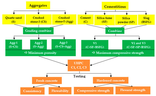
Figure 1.
Steps of the experimental procedure.
2. Materials
In the present study, the UHPC mixture was developed with local materials in Vietnam. The typical composition materials include cement, silica fume, silica powder, quartz sand, crushed stone (CS-3 and CS-5), superplasticizer, and blast furnace slag (BFS), as shown in Table 1. Adding mineral admixtures to replace cement can improve the quality of concrete [17].

Table 1.
Composition of UHPC.
In the cement–slag–water mixtures, BFS participates in hydration, curing, and strength development, as an active mineral additive component. BFS has a grain shape, slightly angular, and the grain diameter is around 20–35 µm. The basic composition of BFS consists of silicates and calcium aluminosilicate. Commercial products of crushed slag generally have Blaine fineness from 4000 to 5000 cm2/g, density 2500–2950 kg/m3, and bulk density from 1050 to 1375 kg/m3 [25].
Adding the slag to the binder mixture induces an increase in the calcium silicate hydrate (C-S-H) ratio in the microstructure of cement paste [22,26]. Accordingly, the Ca(OH)2 in the mixture reacts with the minerals of slag to form a cohesive product, which increases the toughness of the microstructure. In addition, the space occupied by water is divided by the hydration products; hence, the porosity in the cement paste is reduced [27,28]. The present study employed the slag containing the chemical composition, as reported in Table 2. The use of BFS enhanced the resistance of concrete to seawater and waterproofing ability [29,30] due to the pozzolanic reaction.
Table 2.
Chemical composition of BFS.
Other significant ingredients of UHPC are three aggregates including quartz sand, crushed stone-3 (CS-3), and crushed stone-5 (CS-5). In the present study, the compressive strength of the stone approximately reached 130 MPa and the content of aggregate particles passing through the sieve is shown in Table 3. Three aggregates were in turn combined and mixed in certain proportions to determine the minimum porosity between the particles.
Table 3.
Content of aggregate particles passing through the sieve.
3. Experiments and Results
The present study employed the packing density method to select the composition of aggregate and cement paste. The main goal of the PDM is to select the consistency of the concrete. Optimizing components of concrete enhances the stabilization of the aggregate structure and reduces the pore volume and pore size. The experiments are conducted in both aggregates and cement paste. It is the classification of the grain sizes, from coarse to fine and superfine aggregates, which determines the overall performance of the material.
3.1. Effect of Aggregate Grading on the Mixture Porosity
The arrangement of aggregates shows a significant effect on the performance of the concrete mixture, and the strength of the original rock also affects the mechanical properties of concrete. However, the amount of mixed aggregates in the UHPC matrix can reduce the workability of fresh concrete [31,32,33]. Therefore, an appropriate ratio of ingredients with the lowest porosity should be considered in designing a concrete mixture.
The aggregate components, as shown in Figure 2a, were mixed at predetermined ratios. For each case in Table 4, the aggregate mixture was filled into the glass box and vibrated to compact the particles as shown in Figure 2b. Then, the mixture in the box was flattened and weighed to determine the compaction coefficient (c) and porosity (n).
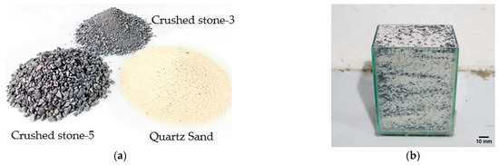
Figure 2.
Aggregate composition. (a) Aggregates, (b) Glass box.
Table 4.
Cases of the aggregate mixture.
Agg-1 includes quartz sand and crushed stone-3. The results show that the porosity gradually decreases until the value reaches the minimum value (n = 0.302), corresponding to the mixing ratio of 30% quartz sand and 70% crushed stone-3, as shown in Figure 3. However, it shows an upward trend when the content of crushed stone-3 increases. The findings indicate that the value (n = 0.302) is the optimal porosity value in case Agg-1.
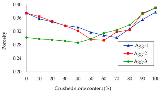
Figure 3.
Porosity of three cases.
Similar experimental procedures and calculations of porosity were applied for Agg-2 and Agg-3. The present study investigated case Agg-2 with the ratio of two components (sand and crushed stone-5) varied from 0 to 100%. As shown in Figure 3, the porosity of Agg-2 decreases when the aggregate increases from 10% to 60%. However, from the value of 70% crushed stone-5, the porosity increases significantly. It can be seen that the angular shape of the particles can increase the gap between particles. Thus, the mixing ratio of 60% crushed stone-5 and 40% quartz sand was selected as the optimal value for Agg-2 (n = 0.294).
Agg-3 is the composition of quartz sand, crushed stone-3, and crushed stone-5. Firstly, the optimal selected mixture in Agg-1 was employed, which was 30% quartz sand and 70% crushed stone-3. After that, the selected mixture was combined with crushed stone-5 in which the mixing ratios were changed from 0 to 100%. After mixing, the porosity of Agg-3 was evaluated and presented in Figure 3. Agg-3 shows the same trend as the others. However, the porosity gradually decreases and reaches the lowest value (n = 0.287) at the mixing ratio of 60% (quartz sand + crushed stone-3) and 40% crushed stone-5. This is also the lowest value in all three cases. The porosity increases when the crushed stone-5 ratio is higher than 40% in the mixture. Therefore, the ratio of 60% (quartz sand + crushed stone-3) and 40% crushed stone-5 was chosen in the composition of the concrete mixture for Agg-3.
According to the present findings, the content of aggregates related to the lowest porosity values for each case is presented in Table 5. The lowest porosity values are associated with the highest compacting coefficients. The reasonable grain arrangement leads to reducing the porosity of the mixture, which can improve the quality and durability of UHPC [5,34]. The selected aggregate ratios in Table 5 were used in combination with the cement paste in the next step.
Table 5.
Selected aggregate ratios.
3.2. Factors Affecting the Strength of Hardened Cement Paste
The strength of hardened cement paste is one of the main factors that affect the UHPC strength. Cement paste fills the gaps and glues the aggregate particles into a homogeneous material during the setting process. The increase in cement paste strength enhances the hardness of the concrete material. The present study used two types of silica fume: densified and undensified. The content of silica powder and slag was varied in the mixture to evaluate the effect on the strength of the cement paste.
The ratio of water to binder (W/B) is a necessary parameter in choosing the ingredients of the mixture. The ratio should be lower than the value of 0.25 to ensure a reasonable balance between the flow properties of the concrete and the strength of the hardened concrete [34]. The present study employed a W/B ratio (0.161). All samples of each group were checked for flow, as shown in Figure 4. After tapering, the mixture flowed evenly in all directions with a round shape. In addition, the surface of the cement paste did not show a stratification or water separation phenomenon. The samples were divided into three groups with the powder composition as follows:
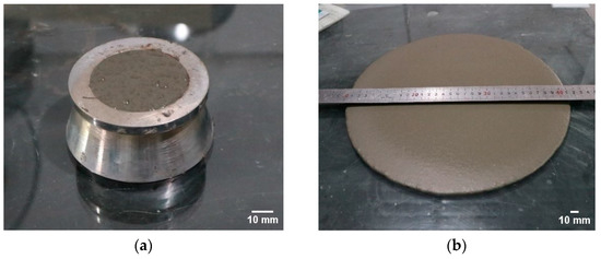
Figure 4.
Flow of the cement paste. (a) Flow test mold, (b) Measuring the flow of cement paste.
- V1 group: cement, densified silica fume, and blast furnace slag;
- V2 group: cement, densified silica fume, blast furnace slag, and silica powder;
- V3 group: cement, undensified silica fume, blast furnace slag, and silica powder.
In the groups (V1, V2, and V3), the ratio of components was calculated based on the cement content, in which the silica fume is 10% of the cement content, and the superplasticizer is equal to 2% of the cement content. The total content of the silica powder and slag varied from 0 to 40% of the cement content.
To examine the compressive strength, the prism samples (40 × 40 × 160 mm) were fabricated. The surface (40 × 40 mm) was subjected to a compressive load. Each group includes three cases relating to 3, 7, and 28 days. Each case has three specimens, as shown in Figure 5a. The specimens were under compressive load until the failure occurs. Figure 5b shows the shape of a sample after testing.
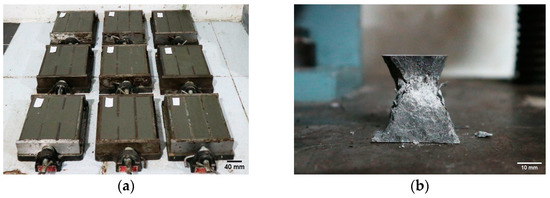
Figure 5.
Testing sample for cement paste. (a) Specimens of cement paste, (b) The shape of a sample after testing.
3.2.1. V1 Group
The powder composition of the V1 group includes cement, silica fume, and blast furnace slag. The total amount of binder was kept constant in all cases of the V1 group. The slag content was employed as follows: 0%, 15%, 20%, 25%, 30%, and 40% of the cement weight. The weight of the mixture, the flow, and the mixing time of the cement paste were reported in Table 6. Accordingly, the flow of cases in the V1 group is relatively similar to each other. In addition, the increase in slag content induces a rise in the mixing time. The phenomenon can be explained by slippery surfaces and low water absorption of slag, as indicated in previous studies [35].
Table 6.
Mixing time, flow, and compressive strength of V1 samples.
The compressive strength of the samples is shown in Table 6 and Figure 6. In cases (V1-0, V1-15, and V1-20), the compressive strength tends to increase during testing from 3 to 28 days. Most samples achieve the early high strength at 7 days, and case V1-20 gives the highest value at 28 days (114.60 MPa), corresponding to 20% slag content. However, cases V1-25, V1-30, and V1-40 show another trend compared with the other cases in group V1. The compressive strength in each case (V1-25, V1-30, and V1-40) reaches the highest value at 7 days. In addition, the compressive strength in the samples tends to increase at 7 days but decrease at 28 days with the rise of the slag ratio (from 25 to 40%). The deviation between the highest value (V1-20) and the lowest value (V1-40) at 28 days is 18.5%. It can be explained that the increase in the slag ratio in the total binder content leads to a decrease in the amount of cement. Therefore, the amount of Ca(OH)2 produced by the hydration process decreases, which induces the reduction of the C-S-H content. Moreover, if too much slag is used, the slag does not react completely, and the excess in the mixture affects the quality of the cementitious phase. These findings suggest that slag content should be selected equal to 20% of cement content to achieve optimal strength.
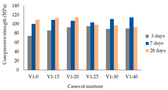
Figure 6.
Compressive strength of V1 group.
3.2.2. V2 Group
Some samples including cement, silica fume, slag, and silica powder in the binder are produced to evaluate the effect of slag and silica powder on the strength of the hardened cement paste. To increase consistency and cohesion with the material, the volume fraction of mortar is about 50–65% of the volume of concrete (45–60% mass equivalent) [25]. Therefore, in these groups, the total amount of slag and silica powder was selected at about 40% of the cement content. The content of slag or silica powder varied from 0 to 80% of the total weight, corresponding from V2-0 to V2-80 mixture notation.
The compressive strength of the V2 group reaches approximately 100 MPa at the age of 7 days, and the strength is higher in the groups with a slag content of 50% or more. The compressive strength of samples in the V2 group at 28 days is relatively similar to each other, as shown in Figure 7. However, the strength at 28 days shows a slight decrease in slag content from 50% to 80% slag.
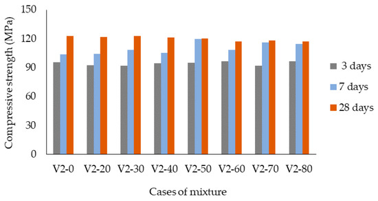
Figure 7.
Compressive strength of V2 group.
3.2.3. V3 Group
The cross-section sample of the V2 group shown in Figure 8a contains many small light-gray spots evenly distributed on the sample surface, which are insoluble silica-fume particles and do not participate in the pozzolanic reaction. The binder composition of the V3 group is similar to that of the V2 group, in which the silica fume in the V3 group is the undensified type. The samples of the V2 and V3 groups were employed to evaluate the effect of silica fume types on the strength of hardened cement paste.
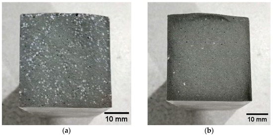
Figure 8.
Cross-sections of samples. (a) V2 group, (b) V3 group.
The testing procedure was done similarly to the V2 group. The mixing time of the V3 group (using undensified silica fume) is much less than that of the V2 group (using densified silica fume). V3 samples were cut and inspected on the surface after they had been hardened. Figure 8b shows a surface with no silica fume particles. It means that the silica fume has been fully reacted in the mixture.
After 3 days of sample fabrication, the compressive strength increases by 70% compared with the value of 28 days and reaches about 80–95% at 7 days as shown in Figure 9. At 28 days, the compressive strength of the V3-50 sample reaches the maximum value (154.83 MPa). V3-50 denotes 50% silica powder and 50% slag in the total 40% cement content, corresponding to 20% of the cement content for each ingredient. Thus, V3-50 is the optimal ratio for the cement paste of the V3 group.
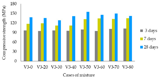
Figure 9.
Compressive strength of V3 group using undensified silica fume.
It can be seen that using undensified silica fume allows silica fume to react completely in the pozzolanic reaction, increasing the amount of C-S-H in the hardened cement paste. Therefore, the compressive strength of the V3 group is higher than that of the V2 group, as presented in Figure 10. Accordingly, the ingredients of V3-50 were used to design the UHPC component in the present study.
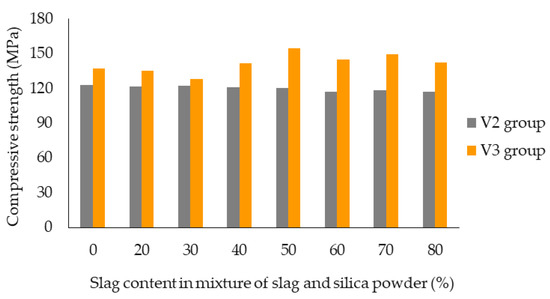
Figure 10.
Compressive strength of V2 and V3 groups at 28 days.
3.3. Proposing Components for UHPC
The composition of UHPC includes two phases: aggregate and cement paste. The composition of the cement paste has been selected including cement, silica fume (equal to 10% cement), blast furnace slag (equal to 20% cement), silica powder (equal to 20% of cement), water, and superplasticizer (equal to 2% cement). In addition, the aggregate compositions are divided into three groups, corresponding to the mixture ratios with the lowest porosity value. The specimens of UHPC are denoted as C1, C2, and C3, as listed in Table 7.
Table 7.
Aggregate components for 1 m3 of concrete.
3.3.1. Properties of Fresh Concrete
- Consistency of the mixture
Concrete mixtures corresponding to C1, C2, and C3 were tested for consistency according to DIN EN 12350-4: 2009-08 standard [36]. Laboratory equipment including a standard container and a vibrating table was used to compact the mixture. The container in the form of a box with sizes (200 × 200 × 400) mm was wiped with a moisture towel before testing. The concrete mixture was filled into the box which was placed on the vibrating table for 5 min, as shown in Figure 11. The lowering level (Si) of the mixture was measured from the top of the container to the position of the concrete surface at each edge. The degree of compactability of the mixture is presented in Table 8. Accordingly, all collected values of the degrees of compactability are smaller than the specified value of the standard (1.04). The findings reveal that the aggregate and mortar are compacted, and the cementitious phase effectively fills the gaps between the aggregate particles.
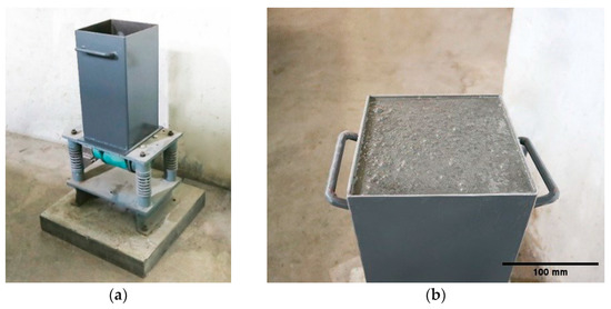
Figure 11.
Testing the consistency of fresh concrete. (a) Container and vibration table, (b) Compacted concrete.
Table 8.
Measurement of the compactness of fresh concrete.
- b.
- Flowability of the mixture
The flow is one of the methods to determine the consistency of fresh concrete. After mixing the concrete, the concrete mixture was filled into the cone mold to measure the flow. The measured results for the sample groups are reported in Table 8. The concrete flow reached a diameter of 750 mm with specimen C2 (aggregate of crushed stone-5 and quartz sand). The workability of the concrete mixture was maintained for 30 min. Figure 12 shows the uniform distribution of the mixture, without the phenomenon of water separation, stratification, or sedimentation of aggregate. Moreover, it can be seen that the C1 sample using quartz sand and crushed stone-3 in the aggregate increases flow time and decreases the workability of the mixture.
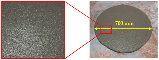
Figure 12.
Flow diameter of UHPC.
3.3.2. Compressive and Flexural Strength of UHPC
The cylindrical samples with a diameter of 150 mm and a height of 300 mm were fabricated to examine the compressive strength, according to the instructions of standard ASTM C39/C39M-2015 [37], as shown in Figure 13a. The samples did not remain in the initial shape after testing, as illustrated in Figure 13b. The experimental results are presented in Figure 14a. The C2 sample shows the highest compressive strength (150.98 MPa) at 28 days. The C1 and C3 samples give the results of 129.25 MPa and 122.98 MPa, respectively. The concrete strength significantly increases, reaching about 75–85% at 3 days and 90–95% at 7 days in comparison with the strength of 28 days. In addition, the C3 sample did not achieve the highest strength, although C3 was created from Agg-3 with the lowest porosity. In contrast, C2 shows the highest compressive strength in which the porosity of Agg-2 is higher than that of Agg-3.
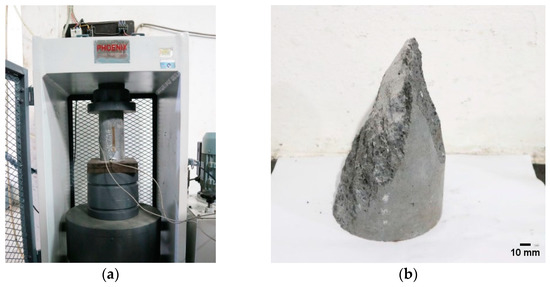
Figure 13.
Compressive testing. (a) Specimen, (b) The shape of a sample after testing.
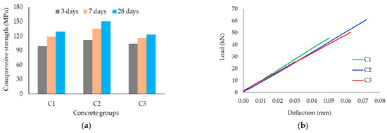
Figure 14.
Experimental results. (a) Compressive strength, (b) Load capacity of the flexural test.
The bending tests followed standard ASTM C78/C78M–18 [38]. The dimensions of flexural samples are 100 mm × 100 mm × 400 mm, relating the width, height of the cross-section, and length. The load was recorded from the load cell mounted on the test device. After installing the equipment, beams were placed on two supports of the testing frame. Measured values were automatically recorded by the computer during loading. The bending test results show the highest value of load capacity (60.88 kN) in the C2 sample. The load capacities of samples C1 and C3 are 45.52 and 50.36 kN, respectively. Figure 14b shows the linear behavior of the load-deflection relationship in three groups from C1 to C3. All specimens suddenly ruptured at the ultimate load.
The obtained results show that the C2 specimen gives the highest value of compressive strength and ultimate bending load. The findings demonstrate that the C2 mixture combining the Agg-2 aggregate with the V3-50 cement paste is the most effective selection for UHPC constituents.
4. Discussion
4.1. Effects of Porosity and Grain Sizes on Compressive Strength
As shown in Figure 3, Table 5, and Section 3.3.2, C1 and C3 have the highest porosity (n = 0.302) and lowest porosity (n = 0.287), respectively. The deviation of porosity between C1 and C3 is 5.2% and 2.4% between C2 and C3. However, the compressive strength of C3 and C1 is lower than that of C2, with 18.5% and 14.3%, respectively. The results do not reflect a parallel relationship between porosity and compressive strength.
C2 contains CS-5 which does not have small-size grains. By contrast, C1 and C3 component includes CS-3 which shows fine aggregates, as reported in Table 3. Therefore, the content of fine particles in C1 and C3 significantly affects the concrete strength.
4.2. Effectiveness of Blast Furnace Slag
The highest compressive strength at 28 days of each group is collected and shown in Figure 15. V3-50 including cement, silica fume, 20% silica powder, and 20% slag achieves the highest value (154.8 MPa). The present findings indicate that the combination of both slag and silica powder (V3-50) is more effective than that of only slag (V1-20) or silica powder (V3-0) in the cement paste.
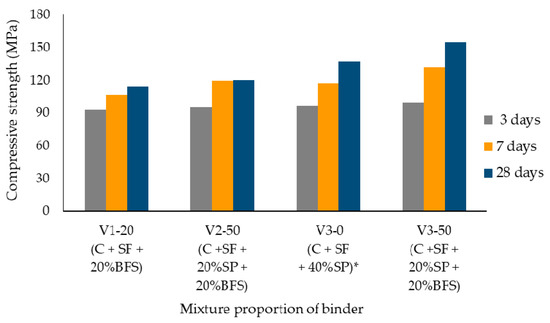
Figure 15.
Comparing the compressive strength of groups. * C: cement, SF: silica fume, SP: silica powder.
It can be seen that adding mineral admixture (silica fume and slag) enhances the microstructure and the compressive strength of concrete [39]. The reaction between slag and Ca(OH)2 increases C-S-H content which improves the strength of the hardened cement paste. The microstructure of the C3-50 sample at 28 days of age was investigated by the scanning electron microscope (SEM) method. Figure 16a shows the sheet-shaped C-S-H and needles crystals of ettringite. Moreover, the C-S-H crystal is recorded as a multilayered structure in Figure 16b. The multilayered crystal reflects the tightly packed and cohesive form [40,41], thereby increasing the compaction of the cement paste.
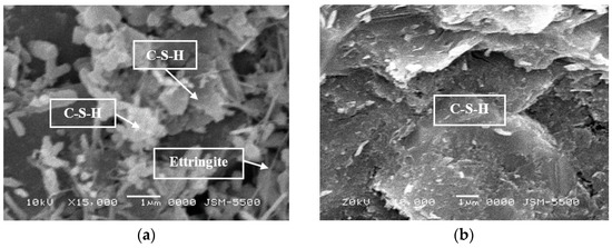
Figure 16.
SEM micrograph of V3-50. (a) 10 kV–15 kx, (b) 20 kV–10 kx.
The findings demonstrate that slag is not only an active mineral additive in the pozzolanic reaction but also a filler contributing to the density of the cement paste. Accordingly, the increase in the compactness of the cement paste enhances the overall hardness of the material.
4.3. Strength Development at Early Age
Previous studies [18,42,43] investigated that using slag in UHPC enhances compressive strength at an early age. The present study obtained the compressive strength of UHPC as approximately 116–136 MPa at 7 days. The equivalent results were confirmed in previous studies [18,42] with approximately 120 and 100 MPa, respectively. Therefore, the present findings are consistent with the previous studies [18,42]. Moreover, the compressive strength of the C2 sample reached approximately 151 MPa, correspondingly at 28 days, which is greater than that in the previous study [42] (approximately 130 MPa) in normal curing conditions. The findings may be explained by the fact that the constituent and particle distribution in UHPC in the present study is more advanced than that in the previous study [42].
The strength development of UHPC plays a key role in reducing the progress of construction work. The compressive strength of C2 in the present study reaches approximately 90% at 7 days while samples in the study [42] only achieve approximately 77%, in comparison with strength at 28 days.
In addition, the cement content for 1m3 is 658 kg in the study [18] and 657 kg in the study [42], which is larger than that of the present study with 600 kg/m3. It indicates that the present study saves 10% of cement, in comparison with other studies [18,42].
4.4. Evaluation of the Cost of UHPC
The cost of UHPC is a challenge for its widespread application in construction. The cost of UHPC depends on the material components, about 4.1–4.4 million VND/1 m3, as listed in Table 9 and Figure 17. It can be seen that the cost of UHPC mainly depends on the cost of silica powder and cement content, occupying approximately 50%. Thus, a reasonable combination of slag and silica powder in the mixture leads to a reduction in the product cost. Comparing the cost of cement paste in V3 group, V3-50 (Cement + silica fume + 20% silica powder + 20%BFS) shows a lower cost than V3-0 (Cement + silica fume + 40% silica powder), approximately 18%. An explanation for this issue is that the cost of silica powder is more expensive than that of slag (BFS).
Table 9.
Comparison of the cost–strength relationship of UHPC.
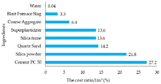
Figure 17.
The cost ratio of the components in 1 m3 of concrete (C2 sample).
Specimen C2 shows the highest cost, as presented in Table 9. However, the ratio of cost to the compressive strength of the C2 group is the lowest (29,227 VND/MPa), in comparison with that of the C1 and C3 groups. Therefore, the C2 sample gives the best economic efficiency. However, the present study does not conduct a comparison with other works because the cost of raw materials depends on various regions.
5. Conclusions
The current study investigated the UHPC constituents in both phases: aggregate and cement paste. Aggregates including quartz sand, crushed stone-3, and crushed stone-5 were combined to choose the proper ratio of the mixture. In addition, the content of silica powder and slag was varied to select the appropriate binder for cement paste achieving the highest compressive strength. The chosen binder was combined with aggregates to find out the optimal composition of UHPC. The conclusions can be drawn as follows:
- Agg-2 (Quartz sand and crushed stone-5) used for C2 is the selected ratio of aggregates. The average compressive strength of C2 samples can reach about 150 MPa. The present findings indicate that the porosity of aggregates is not directly proportional to the compressive strength of UHPC samples, in considering groups C1, C2, and C3;
- Fine aggregate of crushed stone-3 is one of the main factors that reduce the compressive strength of concrete;
- Adding blast furnace slag to the concrete mixture leads to an increase in the flowability of the mixture, with over 700 mm of fresh-concrete flow. In addition, the multilayered structure (C-S-H) of the pozzolanic productions can enhance the hardness of hardened cement paste;
- V3-50 (Cement + silica fume + silica powder + BFS) is the best composition of the binder, with the highest compressive strength of cement paste. The proper ratio of silica powder and BFS is 20% for each ingredient, compared with cement content. In addition, the compressive strength of hardened cement paste using undensified silica fume (V3 group) is better than that of using densified silica fume (V2 group);
- The present study contributes reasonable mixture-proportioning to existing knowledge of UHPC. Accordingly, the particle distribution of UHPC in the present study is more effective than that of the previous study [42]. The compressive strength at the early age of 7 days agreed with that of previous studies [18,42]. Moreover, the strength at 7 days achieved 90% of the strength at 28 days. Therefore, the construction schedule could be shortened due to the strength development of UHPC;
- The combination of silica powder and blast furnace slag could reduce the product cost, improve the performance of concrete, and protect the environment by treating waste from the steel industry.
The present study investigated the mechanical properties of plain concrete. Therefore, in the future, the effect of the combination of aggregate particle sizes and steel fibers on concrete performance should be studied.
Author Contributions
Conceptualization, V.T.H.C., V.D.B. and T.V.N.; methodology, V.T.H.C. and V.D.B.; software, V.T.H.C.; validation, V.D.B.; formal analysis, V.T.H.C.; investigation, V.T.H.C. and V.D.B.; resources, V.T.H.C. and V.D.B.; data curation, V.T.H.C. and V.D.B.; writing—original draft preparation, V.T.H.C.; writing—review and editing, V.T.H.C., V.D.B. and T.V.N.; visualization, V.T.H.C. and V.D.B.; supervision, V.D.B. and T.V.N.; project administration, V.D.B. All authors have read and agreed to the published version of the manuscript.
Funding
This research received no external funding.
Data Availability Statement
Not applicable.
Acknowledgments
We acknowledge the support of time and facilities from Ho Chi Minh City University of Technology (HCMUT), VNU-HCM for this study.
Conflicts of Interest
The authors declare no conflict of interest.
References
- Magureanu, C.; Sosa, I.; Negrutiu, C.; Heghes, B. Mechanical Properties and Durability of Ultra-High-Performance Concrete. ACI Mater. J. 2012, 109, 177. [Google Scholar]
- Bahmani, H.; Mostofinejad, D. Microstructure of Ultra-High-Performance Concrete (UHPC)—A Review Study. J. Build. Eng. 2022, 50, 104–118. [Google Scholar] [CrossRef]
- Vande Voort, T.L.; Suleiman, M.T.; Sritharan, S. Design and Performance Verification of UHPC Piles for Deep Foundations; IHRB Project TR-558; Iowa State University, Center for Transportation Research and Education: Ames, IA, USA, 2008. [Google Scholar]
- Teichmann, T.; Schmidt, M. Influence of the Packing Density of Fine Particles on Structure, Strength, and Durability of UHPC. In Proceedings of the International Symposium on Ultra High Performance Concrete, Kassel, Germany, 13–15 September 2004; pp. 313–323. [Google Scholar]
- Abbas, S.; Nehdi, M.L.; Saleem, M.A. Ultra-High Performance Concrete: Mechanical Performance, Durability, Sustainability and Implementation Challenges. Int. J. Concr. Struct. Mater. 2016, 10, 271–295. [Google Scholar] [CrossRef]
- Tayeh, B.A.; Bakar, B.H.A.; Johari, M.A.M.; Voo, Y.L. Mechanical and Permeability Properties of the Interface between Normal Concrete Substrate and Ultra High Performance Fiber Concrete Overlay. Constr. Build. Mater. 2012, 36, 538–548. [Google Scholar] [CrossRef]
- Bui, V.D. Behaviour of Steel-Concrete Composite Beams Made of Ultra High Performance Concrete. Ph.D. Thesis, Leipzig University, Leipzig, Germany, 2010. [Google Scholar]
- Hung, C.-C.; El-Tawil, S.; Chao, S.-H. A Review of Developments and Challenges for UHPC in Structural Engineering: Behavior, Analysis, and Design. J. Struct. Eng. 2021, 147, 03121001. [Google Scholar] [CrossRef]
- Li, J.; Wu, C.; Hao, H. An Experimental and Numerical Study of Reinforced Ultra-High Performance Concrete Slabs under Blast Loads. Mater. Des. 2015, 82, 64–76. [Google Scholar] [CrossRef]
- Li, J.; Wu, C.; Hao, H.; Su, Y. Investigation of Ultra-High Performance Concrete Under Static and Blast Loads. Int. J. Prot. Struct. 2015, 6, 217–234. [Google Scholar] [CrossRef]
- Yu, R.; Van Beers, L.; Spiesz, P.; Brouwers, H.J.H. Impact Resistance of a Sustainable Ultra-High Performance Fibre Reinforced Concrete (UHPFRC) under Pendulum Impact Loadings. Constr. Build. Mater. 2016, 107, 203–215. [Google Scholar] [CrossRef]
- Kim, H.; Hadl, P.; Nguyen, V.T. A New mix design method for UHPC based on stepwise optimization of particle packing density. In International Interactive Symposium on Ultra-High Performance Concrete; Iowa State University Digital Press: Ames, IA, USA, 2016; Volume 1. [Google Scholar]
- Raj, N.; Patil, S.G.; Bhattacharjee, B. Concrete Mix Design By Packing Density Method. IOSR J. Mech. Civ. Eng. 2014, 11, 34–46. [Google Scholar] [CrossRef]
- Yong, S.; Zonglin, W.; Qingfei, G.; Chenguang, L. A New Mixture Design Methodology Based on the Packing Density Theory for High Performance Concrete in Bridge Engineering. Constr. Build. Mater. 2018, 182, 80–93. [Google Scholar] [CrossRef]
- Wong, V.; Chan, K.W.; Kwan, A.K.H. Applying Theories of Particle Packing and Rheology to Concrete for Sustainable Development. Organ. Technol. Manag. Constr. Int. J. 2013, 5, 844–851. [Google Scholar] [CrossRef]
- Park, S.; Wu, S.; Liu, Z.; Pyo, S. The Role of Supplementary Cementitious Materials (SCMs) in Ultra High Performance Concrete (UHPC): A Review. Materials 2021, 14, 1472. [Google Scholar] [CrossRef] [PubMed]
- Yazici, H.; Yardimci, M.Y.; Yiǧiter, H.; Aydin, S.; Türkel, S. Mechanical Properties of Reactive Powder Concrete Containing High Volumes of Ground Granulated Blast Furnace Slag. Cem. Concr. Compos. 2010, 32, 639–648. [Google Scholar] [CrossRef]
- Abdulkareem, O.M.; Fraj, A.B.; Bouasker, M.; Khelidj, A. Mixture Design and Early Age Investigations of More Sustainable UHPC. Constr. Build. Mater. 2018, 163, 235–246. [Google Scholar] [CrossRef]
- Yu, R.; Spiesz, P.; Brouwers, H.J.H. Development of an Eco-Friendly Ultra-High Performance Concrete (UHPC) with Efficient Cement and Mineral Admixtures Uses. Cem. Concr. Compos. 2015, 55, 383–394. [Google Scholar] [CrossRef]
- Shin, H.; Yoo, D.; Lee, J.; Lee, S.; Yoon, Y. Optimized Mix Design for 180 MPa Ultra-High-Strength Concrete. J. Mater. Res. Technol. 2019, 8, 4182–4197. [Google Scholar] [CrossRef]
- Ma, J.; Orgass, M.; Dehn, F.; Schmidt, D.; Nguyen, V.T. Comparative Investigations on Ultra-High Performance Concrete with and without Coarse Aggregates. In Proceedings of the International Symposium on Ultra High Performance Concrete, Kassel, Germany, 13–15 September 2004; pp. 205–212. [Google Scholar]
- Schuldyakov, K.V.; Kramar, L.Y.; Trofimov, B.Y. The Properties of Slag Cement and Its Influence on the Structure of the Hardened Cement Paste. Procedia Eng. 2016, 150, 1433–1439. [Google Scholar] [CrossRef]
- Liu, Z.; El-Tawil, S.; Hansen, W.; Wang, F. Effect of Slag Cement on the Properties of Ultra-High Performance Concrete. Constr. Build. Mater. 2018, 190, 830–837. [Google Scholar] [CrossRef]
- Yang, J.; Peng, G.F.; Gao, Y.X.; Zhang, H. Mechanical Properties and Durability of Ultra-High Performance Concrete Incorporating Coarse Aggregate. Key Eng. Mater. 2015, 629–630, 96–103. [Google Scholar] [CrossRef]
- Kosmatka, S.H.; Kerkhoff, B.; Panarese, W.C. Design and Control of Concrete Mixtures, 14th ed.; Portland Cement Association: Skokie, IL, USA, 2003. [Google Scholar]
- Chen, W.; Brouwers, H.J.H. The Hydration of Slag, Part 2: Reaction Models for Blended Cement. J. Mater. Sci. 2007, 444–464. [Google Scholar] [CrossRef]
- Yang, J.; Li, D.; Fang, Y. Effect of Synthetic CaO-Al2O3-SiO2-H2O on the Early-Stage Performance of Alkali-Activated Slag. Constr. Build. Mater. 2018, 167, 65–72. [Google Scholar] [CrossRef]
- Teng, S.; Lim, T.Y.D.; Sabet Divsholi, B. Durability and Mechanical Properties of High Strength Concrete Incorporating Ultra Fine Ground Granulated Blast-Furnace Slag. Constr. Build. Mater. 2013, 40, 875–881. [Google Scholar] [CrossRef]
- Douglas, E.; Bilodeau, A.; Malhotra, V.M. Properties and Durability of Alkali-Activated Slag Concrete. ACI Mater. J. 1992, 89, 509–516. [Google Scholar] [CrossRef]
- Veiga, K.; Gastaldini, A.L.G. Sulfate Attack on a White Portland Cement with Activated Slag. Constr. Build. Mater. 2012, 34, 494–503. [Google Scholar] [CrossRef]
- Beshr, H.; Almusallam, A.A.; Maslehuddin, M. Effect of Coarse Aggregate Quality on the Mechanical Properties of High Strength Concrete. Constr. Build. Mater. 2003, 17, 97–103. [Google Scholar] [CrossRef]
- Yu, Z.; Wu, L.; Yuan, Z.; Zhang, C.; Bangi, T. Mechanical Properties, Durability and Application of Ultra-High-Performance Concrete Containing Coarse Aggregate (UHPC-CA): A Review. Constr. Build. Mater. 2022, 334, 127360. [Google Scholar] [CrossRef]
- Wu, F.; Xu, L.; Chi, Y.; Zeng, Y.; Deng, F.; Chen, Q. Compressive and Flexural Properties of Ultra-High Performance Fiber-Reinforced Cementitious Composite: The Effect of Coarse Aggregate. Compos. Struct. 2020, 236, 111810. [Google Scholar] [CrossRef]
- Eide, M.B.; Hisdal, J.-M. Ultra High Performance Fibre Reinforced Concrete (UHPFRC)—State of the Art. COIN Project Report 44; SINTEF Building and Infrastructure: Oslo, Norway, 2012. [Google Scholar]
- Richardson, D.N. Strength and Durability Characteristics of a 70% Ground Granulated Blast Furnace Slag (GGBFS) Concrete Mix; RI99-035/RI99-035B; Organizational Results Research Report; Missouri Department of Transportation (MoDOT): Jefferson City, MO, USA, 2006. [Google Scholar]
- Zimmer, U.P.; Reuter, H.-H. Concrete Testing Compact; Verlag Bau+Technik GMgH: Erkrath, Germanu, 2017. [Google Scholar]
- ASTM C39/C39M-01; Standard Test Method for Compressive Strength of Cylindrical Concrete Specimens. ASTM: West Conshohocken, PA, USA, 2012.
- ASTM C78/C78M-18; Standard Test Method for Flexural Strength of Concrete (Using Simple Beam with Third-Point Loading). ASTM: West Conshohocken, PA, USA, 2018.
- Duan, P.; Shui, Z.; Chen, W.; Shen, C. Effects of Metakaolin, Silica Fume and Slag on Pore Structure, Interfacial Transition Zone and Compressive Strength of Concrete. Constr. Build. Mater. 2013, 44, 1–6. [Google Scholar] [CrossRef]
- Masoumi, S.; Zare, S.; Valipour, H.; Qomi, A.M.J. Effective Interactions between Calcium-Silicate-Hydrate Nanolayers. J. Phys. Chem. C 2019, 123, 4755–4766. [Google Scholar] [CrossRef]
- Lee, Y.L.; Wang, W.H.; Lin, F.H.; Lin, C.P. Hydration Behaviors of Calcium Silicate-Based Biomaterials. J. Formos. Med. Assoc. 2017, 116, 424–431. [Google Scholar] [CrossRef]
- Yang, S.L.; Millard, S.G.; Soutsos, M.N.; Barnett, S.J.; Le, T.T. Influence of Aggregate and Curing Regime on the Mechanical Properties of Ultra-High Performance Fibre Reinforced Concrete (UHPFRC). Constr. Build. Mater. 2009, 23, 2291–2298. [Google Scholar] [CrossRef]
- Gupta, S. Effect of Content and Fineness of Slag as High Volume Cement Replacement on Strength and Durability of Ultra-High Performance Mortar. J. Build. Mater. Struct. 2016, 3, 43–54. [Google Scholar] [CrossRef]


Disclaimer/Publisher’s Note: The statements, opinions and data contained in all publications are solely those of the individual author(s) and contributor(s) and not of MDPI and/or the editor(s). MDPI and/or the editor(s) disclaim responsibility for any injury to people or property resulting from any ideas, methods, instructions or products referred to in the content. |
© 2023 by the authors. Licensee MDPI, Basel, Switzerland. This article is an open access article distributed under the terms and conditions of the Creative Commons Attribution (CC BY) license (https://creativecommons.org/licenses/by/4.0/).