Article

Axial and Shear Behavior of Prestressed Damping Isolation Units Using a Spring and Rubbers

1
Department of Architecture Engineering, Kyonggi University, Suwon 16227, Gyeonggi-do, Korea
2
Department of Architectural Engineering, Graduate School, Kyonggi University, Suwon 16227, Gyeonggi-do, Korea
*
Author to whom correspondence should be addressed.
Buildings 2022, 12(9), 1379; https://doi.org/10.3390/buildings12091379
Submission received: 15 July 2022 / Revised: 8 August 2022 / Accepted: 31 August 2022 / Published: 4 September 2022
(This article belongs to the Special Issue Seismic Design of Building Structures)

Abstract

:
This study investigated the axial and shear behaviors of a seismic damping isolation unit (SDI) developed to improve the seismic resistance of suspended ceiling structures. To enhance the energy dissipation of the SDI, it was composed of a spring, embossed rubbers, and prestressed bolts. Twelve specimens were prepared and tested for failure under axial and shear loading. The main parameters were the presence or absence of a spring, loading type, and magnitude of the prestressed force introduced to the bolts to connect the embossed rubbers. The test results showed that in the relationship of axial or shear load–displacement of the SDI, the post-peak behavior tended to be more ductile for specimens with a spring or higher prestressed force magnitude. Consequently, the ductility ratio and equivalent damping coefficient of the SDI with the spring and 0.1 f b y were 3.81 and 0.166, which was 1.06 and 1.20 times higher than the specimens without spring and prestressed force. In addition, the ductility ratio was approximately 1.07 times higher for the SDI specimens subjected to monotonic loading than for those subjected to cyclic loading. Meanwhile, the JIS B 2704−1 and AISC specifications estimated the tensile strength of the SDI specimens subjected to monotonic loading well, but overestimated that of the specimens subjected to cyclic loading. Hence, the JIS B 2704−1 and AISC specifications should be underestimated by 15.7% and 81.7%, respectively, when estimating the tensile and shear loads of the SDI subjected to cyclic loading.

1. Introduction

In general, the non-structural components of buildings are the structures most severely damaged by earthquakes [1], mainly falling from suspended ceiling structures. This is because non-structural components have relatively low seismic resistance compared to structural members [2]. Therefore, ASCE 41−17 [3] and EC 8 [4] specify bracing strengthening methods for enhancing the seismic resistance of non-structural components. The bracing strengthening method is effective in controlling vibration and increasing the stiffness of the suspended ceiling structure [1,5]. However, this has led to the introduction of high horizontal seismic loads, resulting from more severe damage to the outside of the suspended ceiling structure from the wall. Moreover, the installed bracing materials interfere with piping installation, thereby reducing workability [6].
To solve the problems of structural safety and workability, strengthening methods using various new types of clips have been developed [5,7,8]. Luo et al. [8] emphasized that connecting locking bolts between runners and hanger bolts was effective in reducing the number of panels falling off suspended ceiling structures by improving the clamping force. Jiang et al. [7] confirmed that connecting seismic clips between runners and hanger bolts could reduce the lateral displacement of suspended ceiling structures by approximately 65–99%. However, these connecting clips are ineffective at controlling vibrations and dissipating seismic energy because they do not provide ductility to suspended ceiling structures. Therefore, they are ineffective in controlling vibration and dissipating seismic energy [9]. To solve the problems of the connecting clips, a vibration-damping device with springs and/or vibration−proof rubbers has been developed as an alternative to conventional hanger bolts in suspended ceiling structures [10,11]. Kurita et al. [10] and Wu et al. [11] reported that spring- and vibration-proof rubbers were effective in dissipating seismic energy, indicating damping ratios of 50–90% and 10–20% damping ratio, respectively. However, studies on these vibration damping devices for suspended ceiling structures are still in their infancy, and relevant data are still very scarce [2]. Hence, the fundamental data of vibration damping devices developed for a specific purpose should be evaluated preferentially in terms of ductility indices, such as the ductility ratio and equivalent damping coefficient.
This study established fundamental data on the ductility of a seismic damping-isolation unit (SDI), which was developed to enhance the seismic resistance of suspended ceiling structures. To enhance the energy dissipation of the SDI, it was composed of a spring, embossed rubbers, and prestressed bolts. Twelve specimens were prepared and tested to failure under axial and shear loading. The main parameters were the presence or absence of a spring, loading type, and magnitude of the prestressed force introduced to the bolts to connect the embossed rubbers. To examine the ductility of the SDI, post-peak behavior, ductility ratio, and equivalent damping coefficient were analyzed from the cyclic axial or shear load-displacement relationships. In addition, the measured axial and shear capacities of the SDI were compared with the values predicted by JIS B 2704−1 [12] and AISC [13]. Through these analyses, optimal SDI details were proposed to effectively enhance the seismic resistance of suspended ceiling structures.

2. Research Significance

This study provides valuable experimental data on the presence or absence of a spring, loading type, and the prestressed force magnitude effects of seismic damping-isolation units (SDI) on axial or shear behavior. This study proposes optimal SDI details for effectively enhancing the seismic resistance of suspended ceiling structures. This study also confirmed that the prestressing force was the critical factor in effectively enhancing the ductility indices, such as post-peak behavior, the hysteresis loop at each displacement increment, and the equivalent damping coefficient in the axial or shear behavior of SDI.

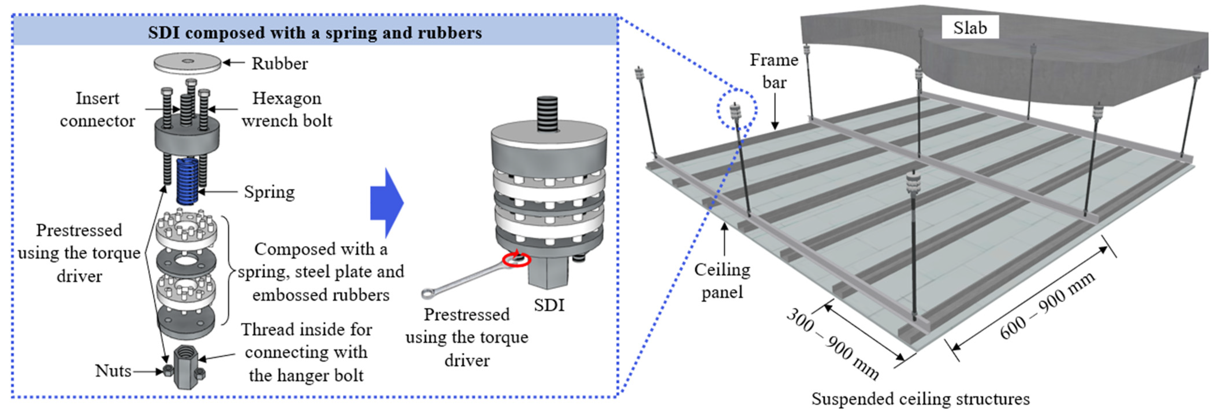
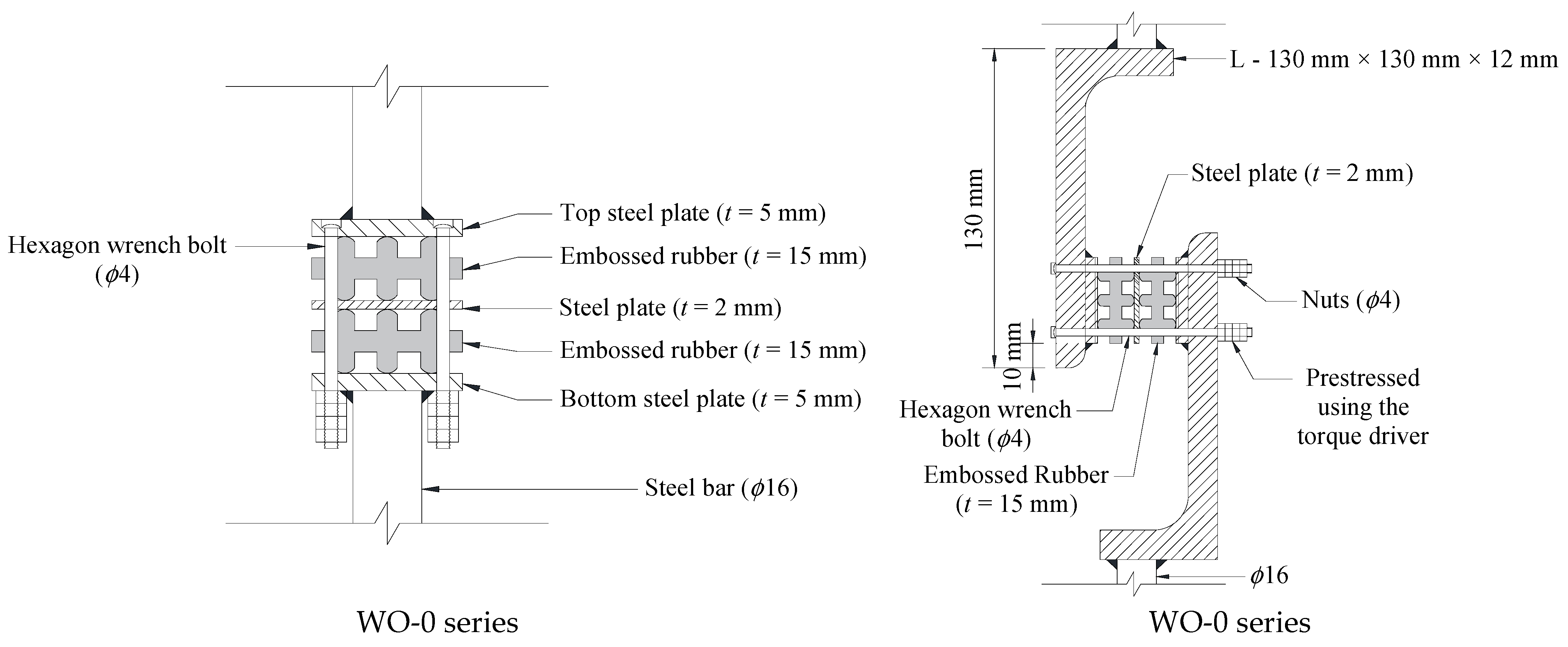
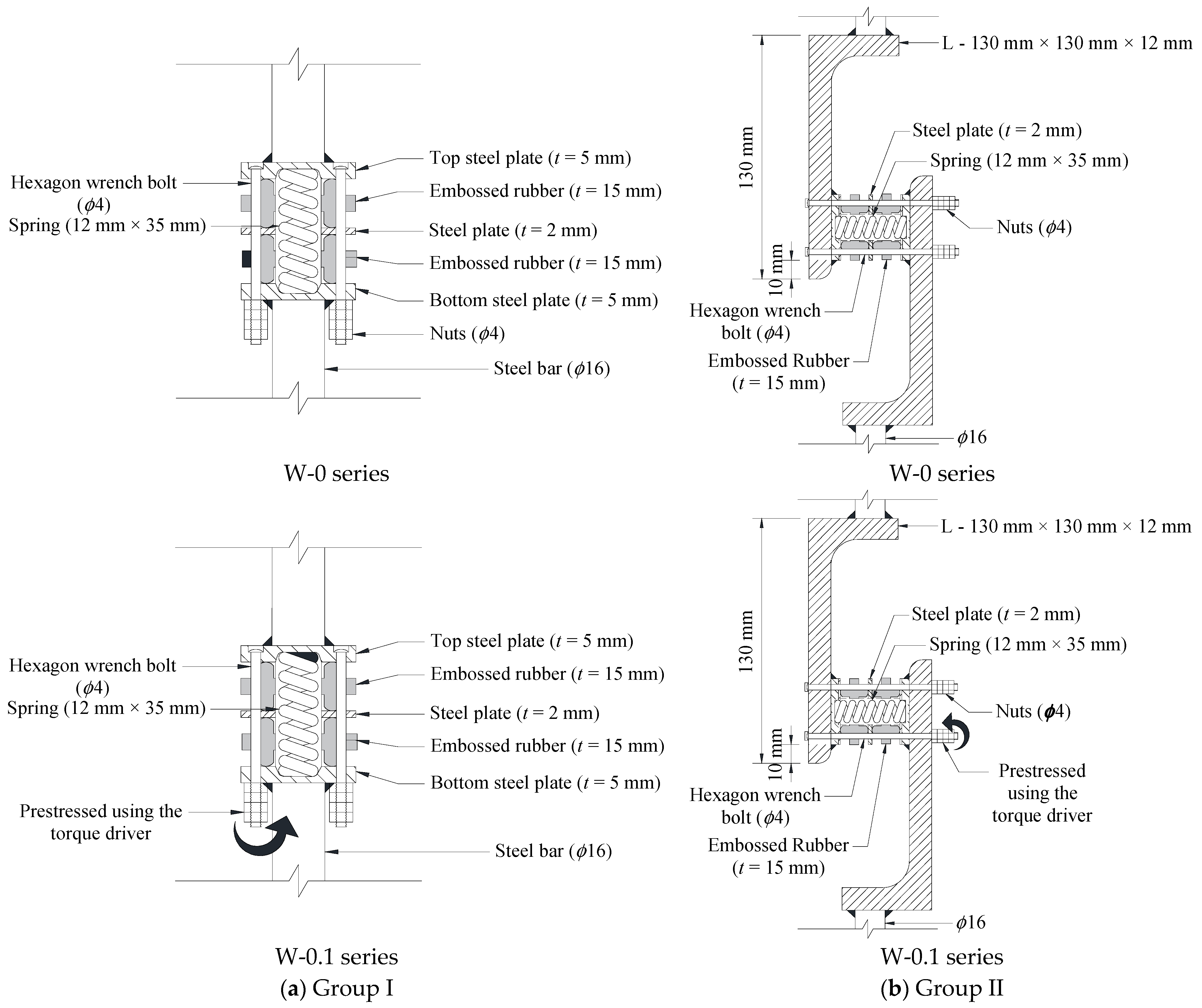
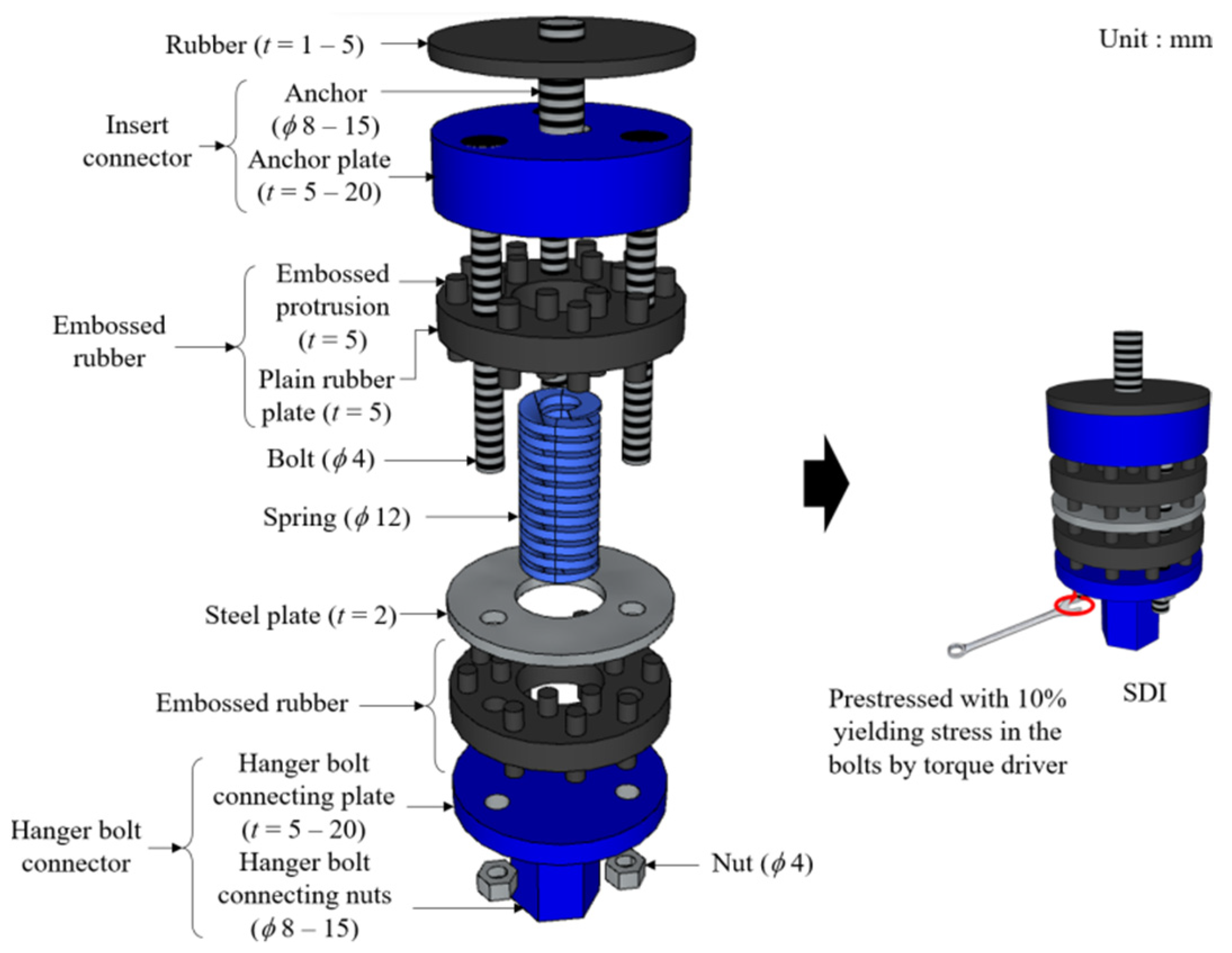
3. Details of Damping−Isolation Unit

Figure 1 shows the details of the SDI for enhancing the seismic resistance of the suspended ceiling structures. The SDI is composed of an insert connector, a spring, a steel plate, embossed rubbers, prestressed bolts, nuts, and a hanger bolt connector. The insert connector was composed of a screw bolt and a plate for connecting the SDI and slab. The embossed rubbers and steel plate were laminated and combined using three screw bolts and nuts, and a spring was inserted in the center. Three screw bolts were prestressed using the torque driver, which had a thread inside to connect to the hanger bolts. Compositions using prestressed bolts are effective in enhancing the damping performance of rubbers and spring [10,11]. Therefore, the SDI is expected to control seismic waves and vibrations from the higher damping performance, resulting in higher energy dissipation and lower demanding shear resistance of suspended ceiling structures.

4. Experimental Investigation

4.1. Test Specimens

Figure 2 shows the details of the SDI specimens based on the main parameters. The specimens were divided into two groups: groups I and II for the specimens subjected to axial and shear loadings (Table 1), respectively. In each group, the main parameters were the presence or absence of a spring, loading type, and magnitude of the prestressed force introduced to the bolts to connect the embossed rubbers. The prestressed force magnitude varied from 0 to 10% of the yielding strength of the bolt ( f b y ), and the loading type was monotonic or cyclic. The specimens were named according to their main parameters. The first letter indicates the presence or absence of a spring (W = SDI with a spring and WO = SDI without a spring), the second number indicates the magnitude of the prestressed force introduced to the bolts (0 = 0 f b y and 0.1 = 0.1 f b y ), and the last letter indicates the loading type (M = monotonic loading and C = cyclic loading).
The total thickness of the embossed rubber was 15 mm and the diameter and height of the protrusions were 5 mm each. There were six protrusions at the top and the bottom. The diameter and thickness of the steel plate inserted between the rubbers were 35 mm and 2 mm, respectively. To install the spring and bolts, the embossed rubber and steel plate had holes with diameters of 14 mm and 4 mm at the center and edge, respectively. The top and bottom plates were threaded so that the spring could be fixed therein and had three holes with a diameter of 4 mm diameter in line with the same position as the embossed rubber and steel plate at the edge. The inner and outer diameters of the spring were 6 and 12 mm, respectively, and the diameter of the spring wire was 1 mm. In addition, the height of the spring was 35 mm. Hexagonal wrench bolts with a diameter of 4 mm were used to easily tighten the bolts using the torque driver.

4.2. Material Properties
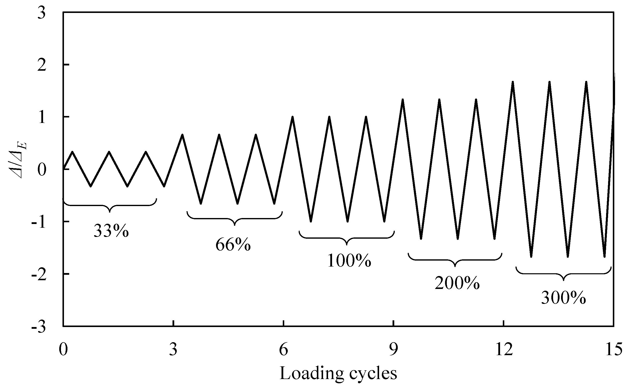
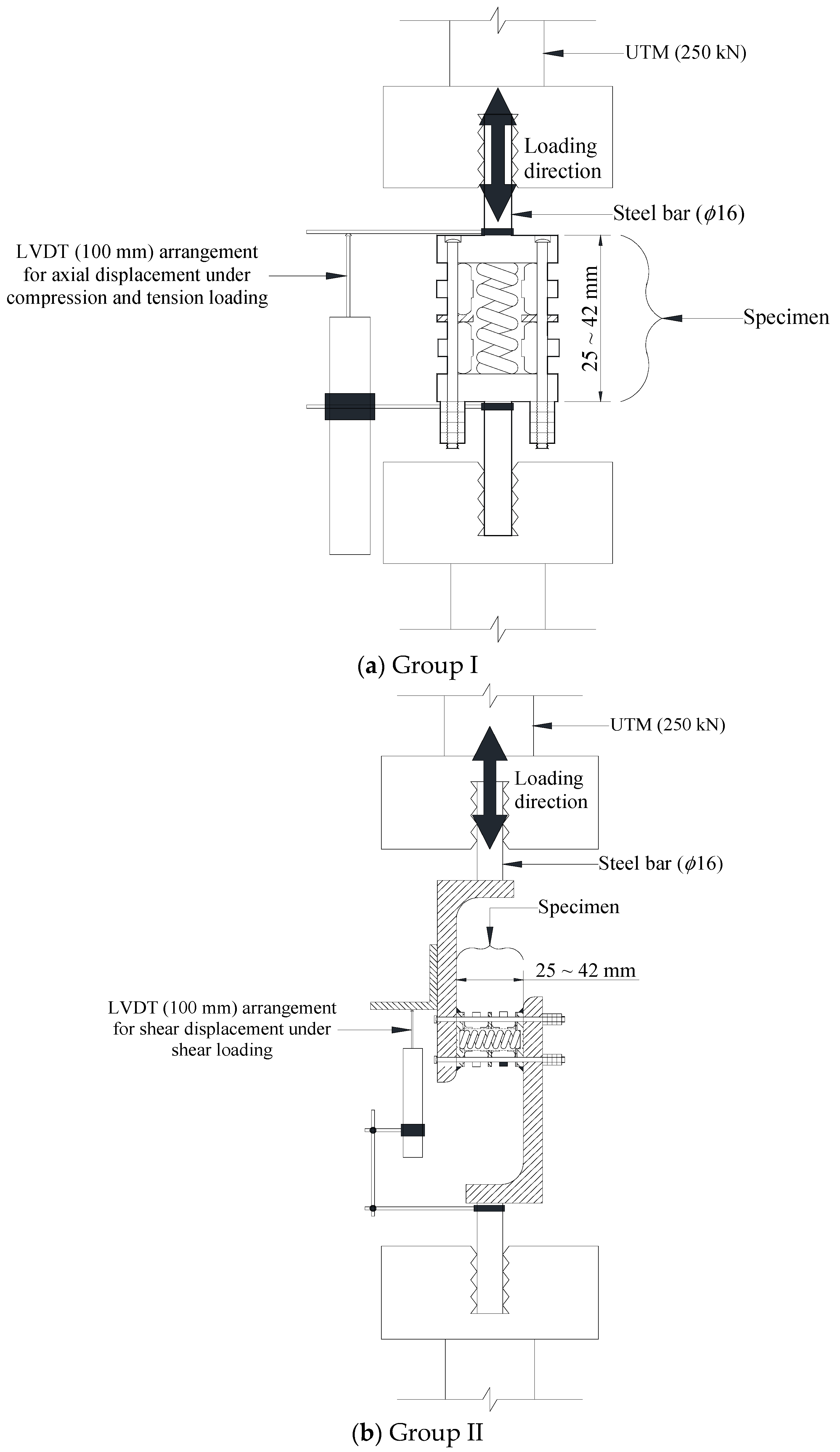
Table 2 summarizes the mechanical properties of the materials used in the SDI. In metallic materials, the yielding strength and elastic modulus were 247 MPa and 169,752 MPa for all the steel plates, 1146.2 MPa and 186,552 MPa for the hexagon wrench bolts, and 1158 MPa and 190,000 MPa for the spring, respectively. In the spring, the stiffness constant ( K ) and free length ( L ) were 7.84 N/mm and 35 mm, respectively. In addition, the compressive and tensile strength of the embossed rubber were 0.81 MPa and 20.3 MPa, respectively.

4.3. Test Set-Up

Figure 3 shows the test set-up for the specimens subjected to axial or shear loading. Axial and shear loads were applied using a universal testing machine a capacity of 250 kN. In group I, monotonic and cyclic axial loads were applied by compressive force up to the design displacement of the spring, and then subjected to tensile force until the specimen failed. In the compression direction, the design displacement of the spring was determined from the spring constant and free field [10]. In Groups I and II, the history of cyclic loading for the specimens subjected to axial and shear loads is shown in Figure 4. During cyclic loading, the incremental displacement at each loading cycle was determined from the elastic limit obtained from the load–displacement of the specimens subjected to monotonic axial or shear loads. The elastic limit point was assumed as 40% of the maximum load in accordance with the allowable stress design [14]. The axial and shear displacements were increased by 33, 67, 100, 200, and 300% of the displacement at the elastic limit point ( Δ E ), and three cycles were iterated at each displacement increment. The axial and shear displacements were measured using a 100 mm capacity linear variable differential transducer (LVDT).

5. Test Results and Discussion
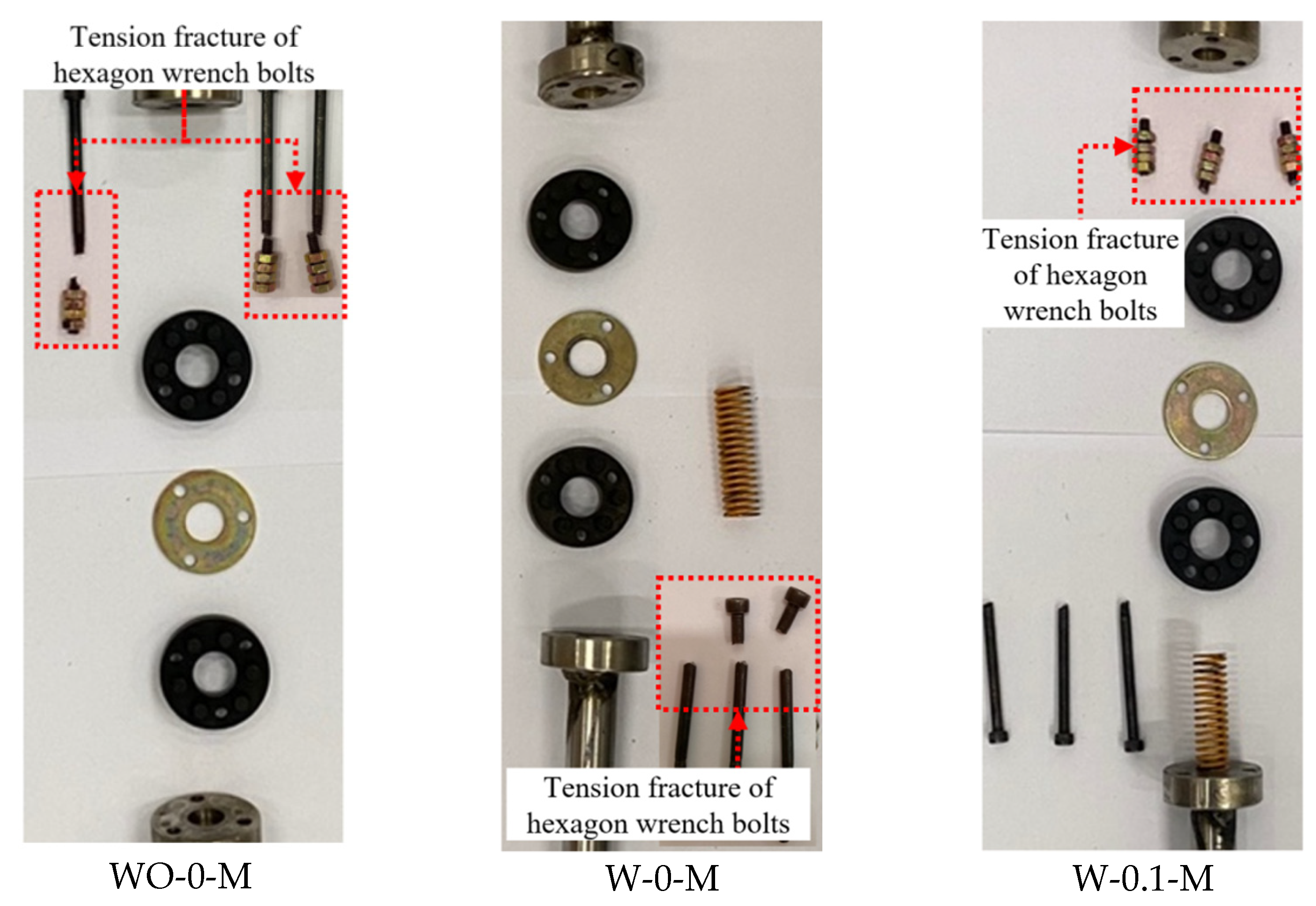
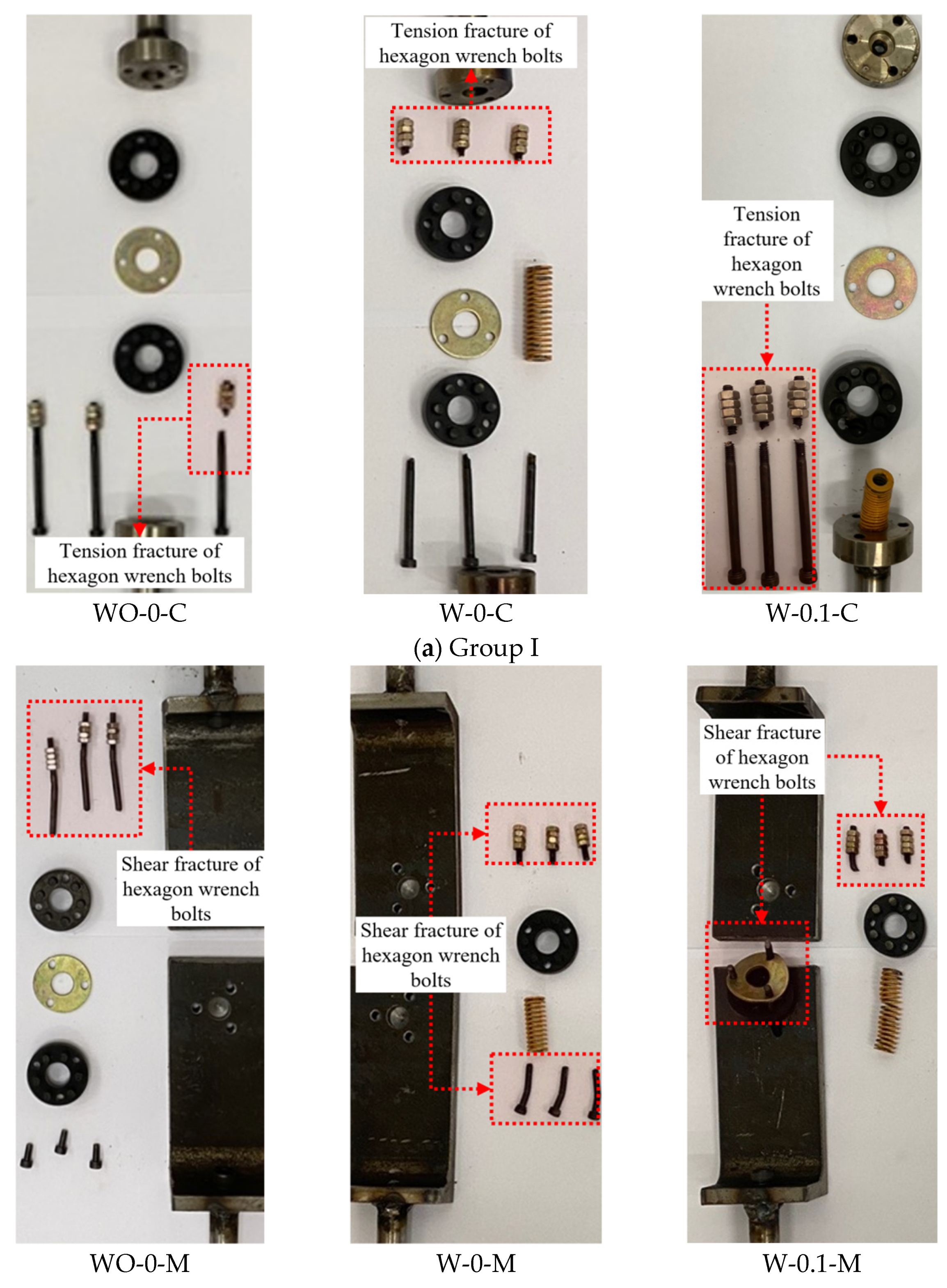
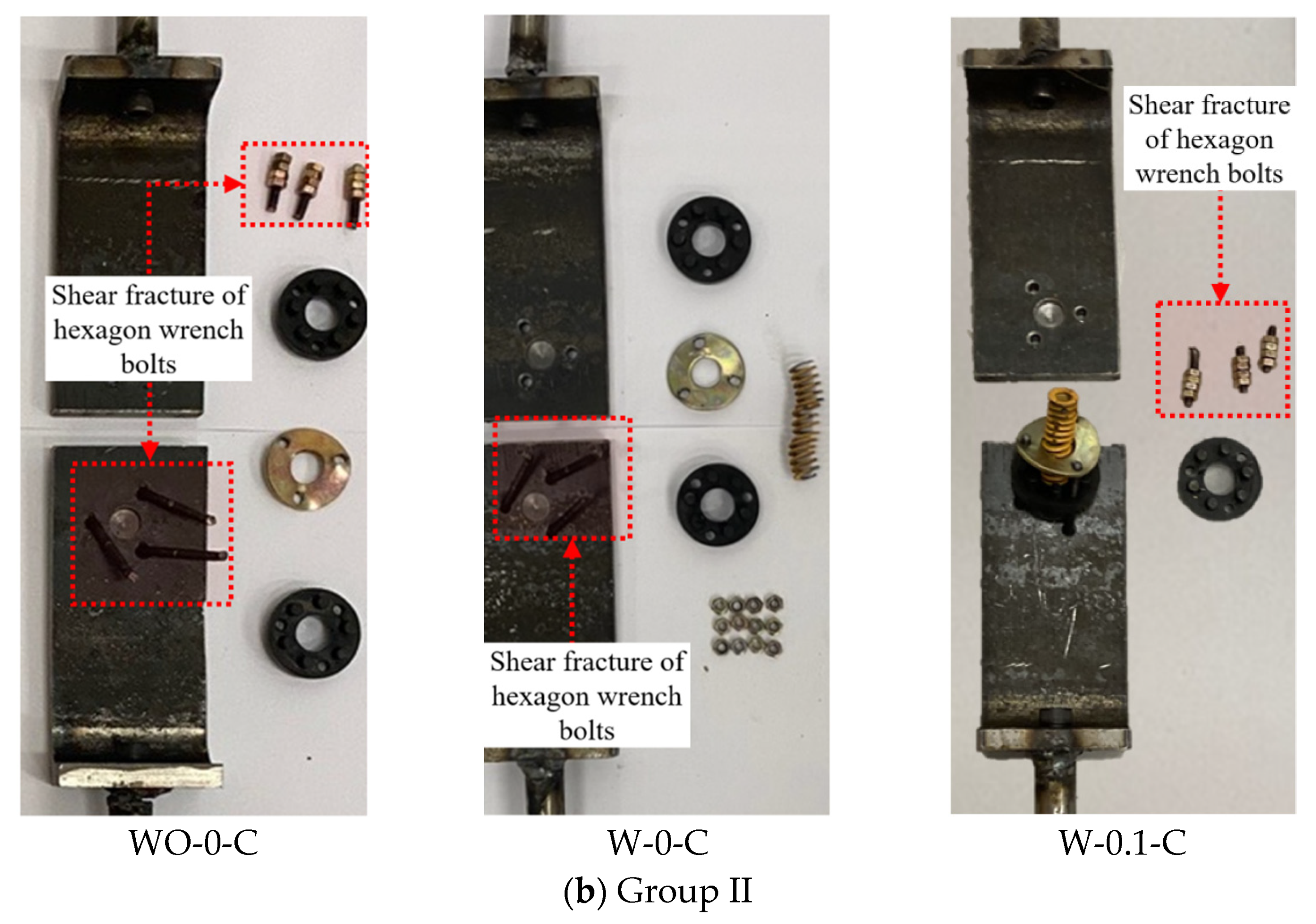
5.1. Failure Mode

Figure 5 shows the failure modes of the SDI specimens subjected to axial and shear loading. In Group I, the specimens subjected to axial loading were governed by tension, and the tension fracture of the hexagonal wrench bolts was observed. The effects of the presence or absence of a spring, prestressed force magnitude, and loading type on this trend were insignificant. The failure mode of the specimens in Group II was similar to that of the specimens in Group I, indicating shear fracture of the hexagonal wrench bolts. The effect of the presence or absence of a spring, prestressed force magnitude, and loading type on the trend observed in Group II was also insignificant. Meanwhile, significant shear deformation was observed in the spring of the SDI specimens subjected to shear loads. However, the axial deformation of the spring was insignificant in SDI specimens subjected to an axial load. This implies that the contribution of the axial or shear resistance was mostly from hexagonal wrench bolts.

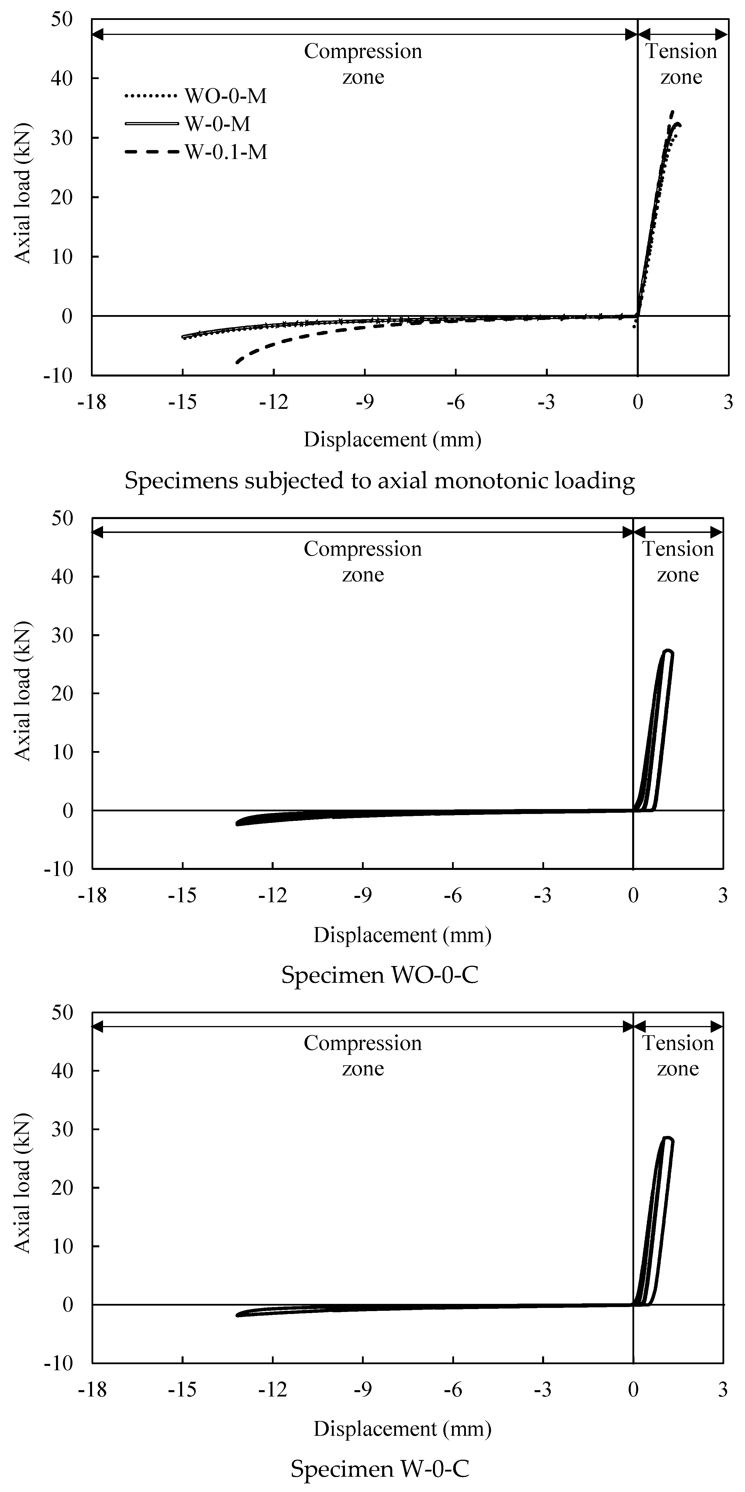
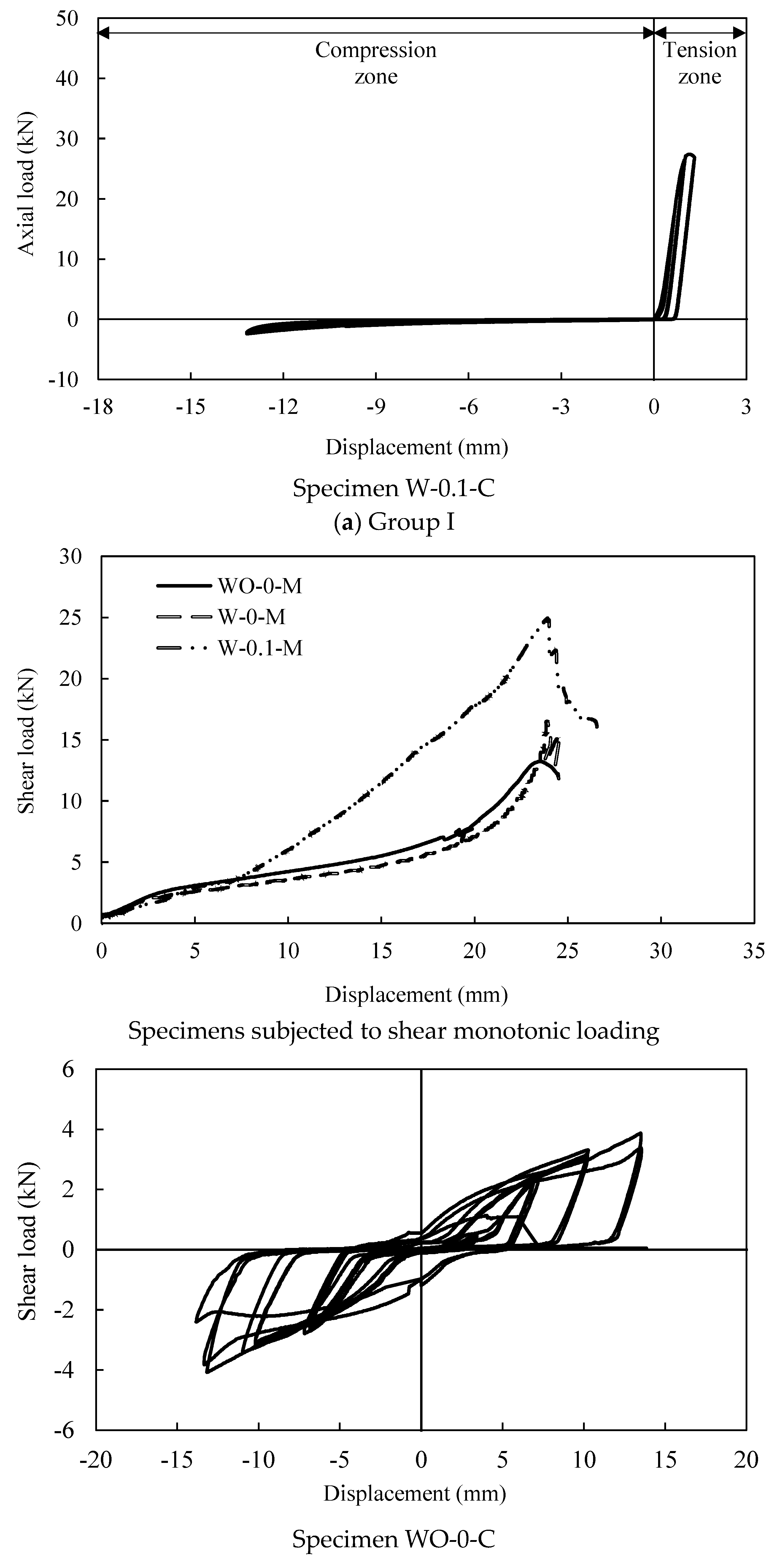
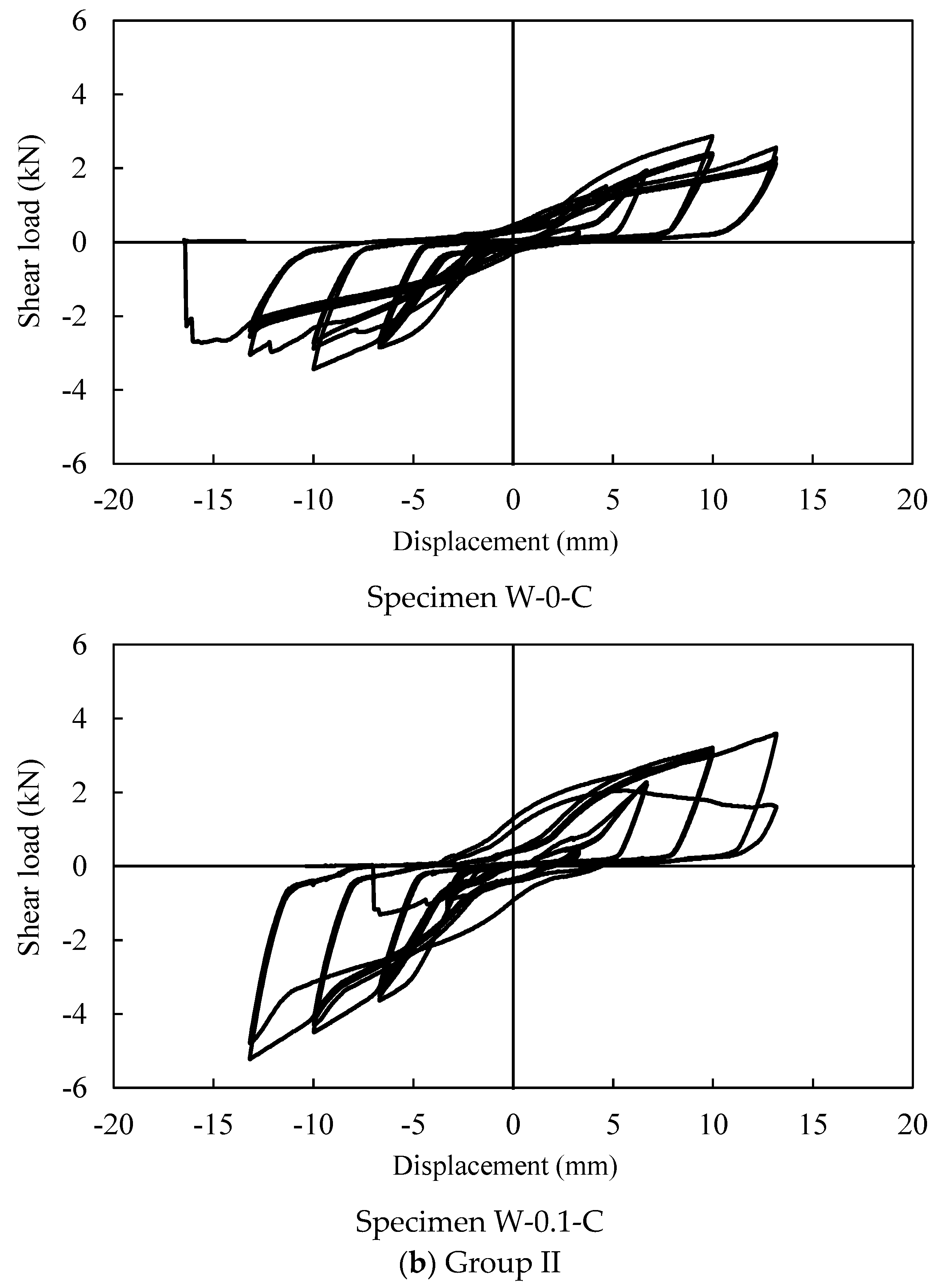
5.2. Load–Displacement Relationships

Figure 6 shows the load–displacement relationship of the specimens subjected to axial or shear loads. The stiffness up to the elastic limit point ( K E ) was significantly affected by the loading type rather than by the presence or absence of a spring or the magnitude of the prestressed force. The K E of the specimens with a spring was 1.26 times higher than that of the specimens without a spring. In addition, when the prestressed force magnitude increased from 0 to 0.1 f b y , K E increased by 1.15 times. In particular, this increasing rate was approximately 1.01 times higher for the specimens under monotonic loading than those under cyclic loading. After Δ E , the stiffness gradually decreased with an increase in axial displacement. After the peak load, the stiffness was affected by the loading type, prestressed force magnitude, and the presence or absence of a spring. The post-peak behavior tended to be more ductile for specimens with a spring and a higher prestressed force magnitude. This trend was more pronounced in the specimens subjected to the monotonic load than the cyclic load. Meanwhile, the effect of the presence or absence of a spring, prestressed force magnitude, and loading type on the trend observed in Group II (specimens subjected to shear loads) was similar to that of the specimens in Group I (specimens subjected to axial loads). Consequently, in the post-peak behavior, the highest ductility was observed in the W-0.1-M series (with a spring and prestressed force magnitude of 0.1 f b y ) that was subjected to monotonic loads. This implies that the presence or absence of a spring, prestressed force magnitude, and loading type significantly affect the ductility of the SDI specimens.

5.3. Maximum Axial and Shear Loads

Table 3 and Table 4 summarize the maximum axial and shear loads of the SDI specimens. The axial loads were divided into two types: compressive and tensile loads. The maximum compressive and tensile loads increased by 1.15 and 1.06 times when the prestressed force magnitude increased from 0 to 0.1 f b y . The rates of increase in the maximum compressive and tensile loads were 1.23 and 1.02 times higher in the SDI specimens with the spring than in those without the spring. In addition, the maximum compressive and tensile loads of the SDI specimens subjected to monotonic load were 1.34 and 1.18 times higher than those subjected to cyclic loading. These trends were similar to those obtained for the specimens observed in Group II (specimens subjected to shear loads). In particular, the maximum shear load of the SDI specimens was considerably affected by the loading type rather than by the magnitude of the prestressed force and the presence or absence of a spring. The maximum shear load of the SDI specimens subjected to monotonic loading was 6.06 times higher than that subjected to cyclic loading. Consequently, the highest compressive, tensile, and shear loads were observed in the W-0.1-M series (with spring and prestressed force magnitude of 0.1 f b y ). This implies that the prestressed force magnitude, spring, and loading type should be taken into account when estimating the maximum axial or shear loads of SDI specimens.

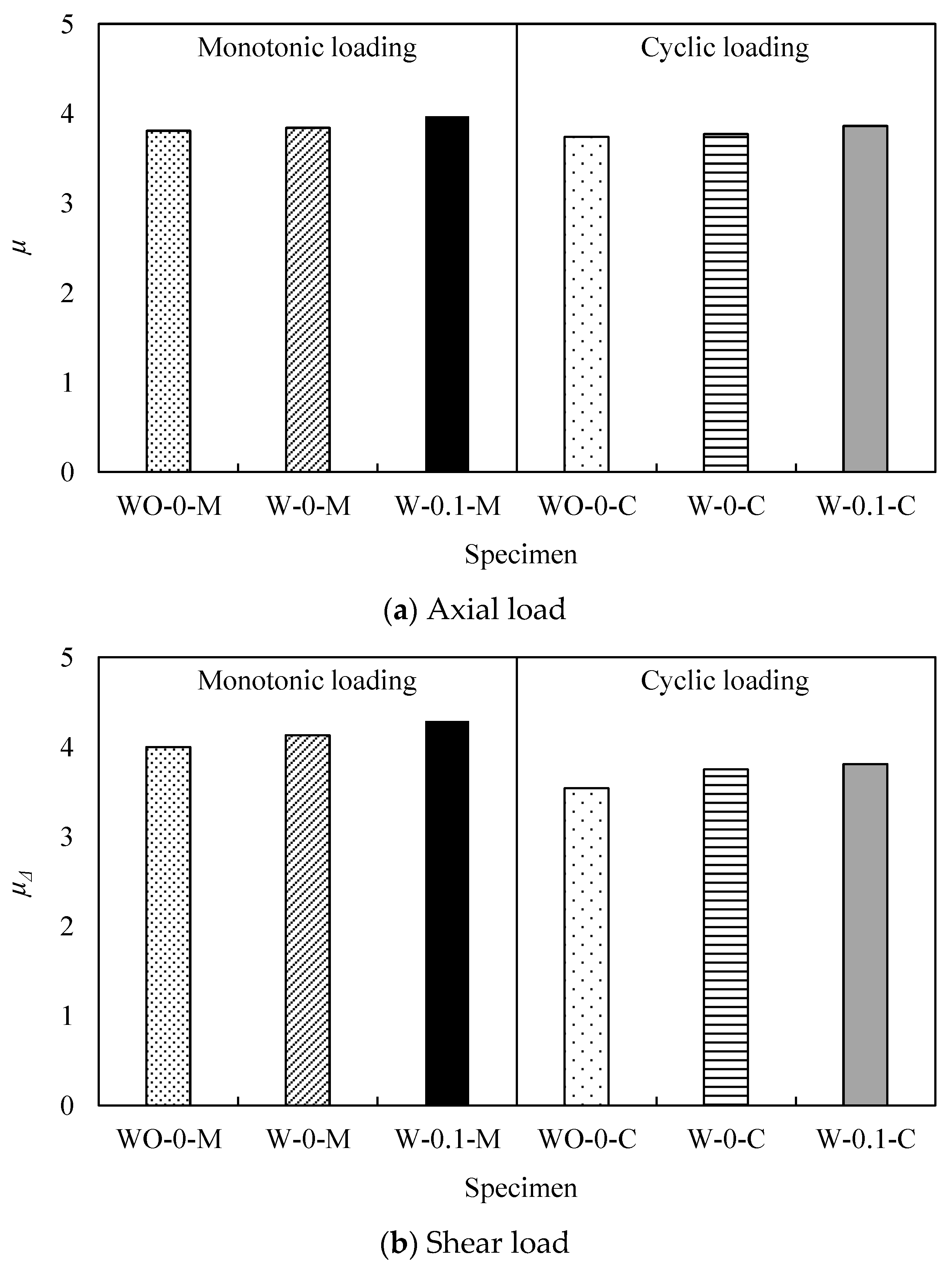
5.4. Ductility Ratio

The ductility ratio of the SDI specimens subjected to axial or shear loads was examined using the following equations [15,16]:
μ = Δ 80 / Δ y   for   the   ductility   ratio   subjected   to   axial   load
μ Δ = Δ 80 / Δ y   for   the   ductility   ratio   subjected   to   shear   load
where μ and μ Δ are the ductility ratios subjected to axial and shear loads, respectively, Δ80 is the displacement at 80% of the ultimate state after the peak load, and Δ y is the displacement at the yielding state. Equation (1) is defined as the μ , which includes the strain in the descending branch of the load-axial strain relationship. Equation (2) is defined as μ Δ , which can include the deformation of post-peak behavior. These ductility indices are commonly used by researchers to investigate the ductility of structural members, such as columns, shear walls, and beams [17,18,19,20,21]. Note that μ and μ Δ were evaluated on the SDI specimens subjected to only axial tensile and shear loads, respectively. In Equations (1) and (2), the Δ y value was assumed to be Δ E because it is difficult to measure. As summarized in Table 3 and Table 4, and Figure 7, μ and μ Δ were significantly affected by the magnitude of the prestressed force and loading type, rather than the presence or absence of a spring. The axial and shear displacement ductility ratios increased by 1.03 and 1.03 times, when the prestressed force magnitude increased from 0 to 0.1 f b y . The corresponding values of the SDI specimens subjected to cyclic loading were approximately 2.1% and 10.6% lower than those subjected to monotonic loading. It was confirmed that the loading type is an important design factor for the ductility of the SDI specimens.

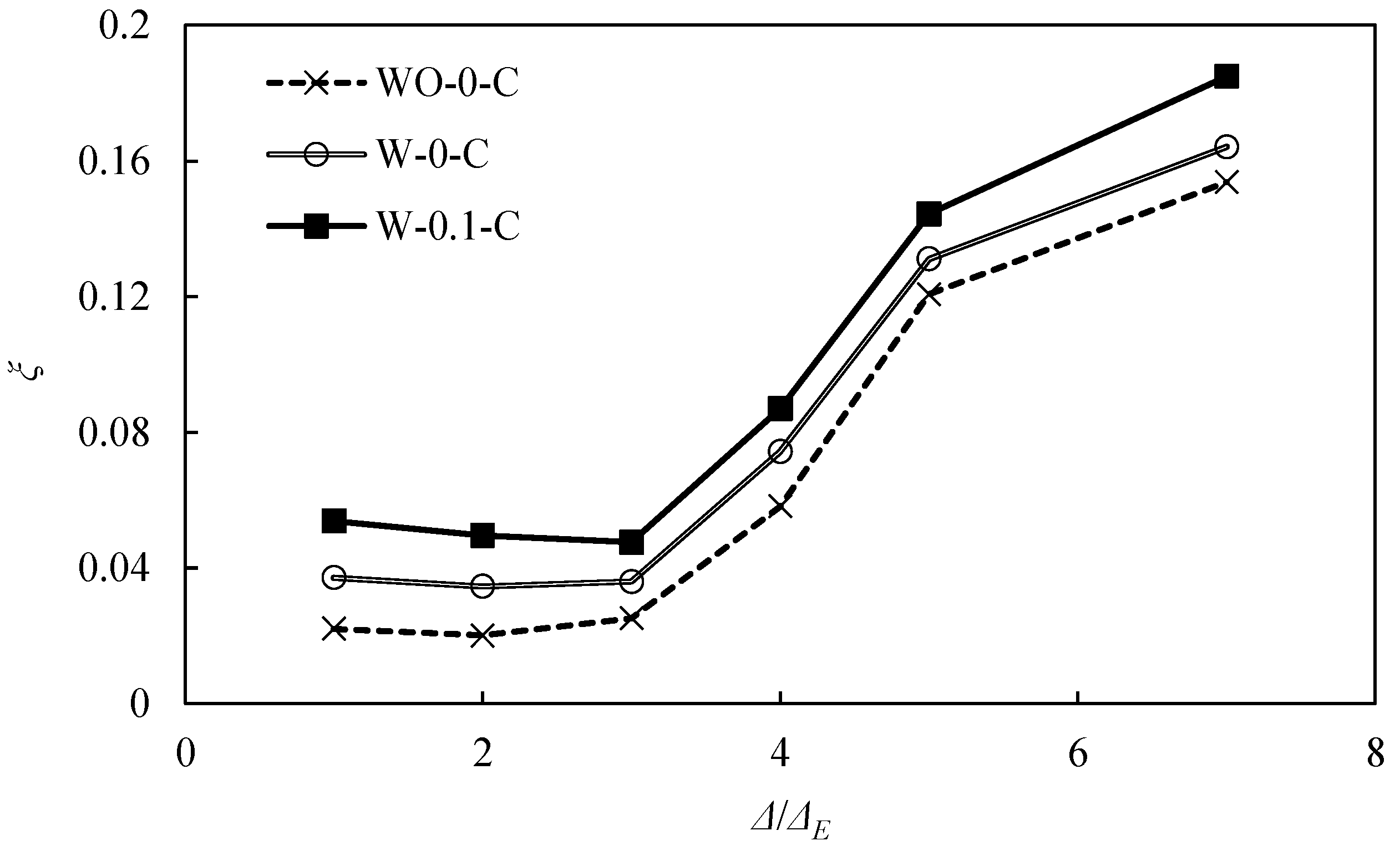
5.5. Equivalent Damping Coefficient

The equivalent damping coefficient (ξ) was examined using the following equations defined by FEMA 356 [22]:
ξ = 1 2 π [ E K 80 Δ 80 2 ]
where E is the sum of the hysteresis loop areas of the specimen and K 80 is the stiffness at 80% of the ultimate state after the peak load. Note that the ξ values were evaluated only for the SDI specimens subjected to shear cyclic loads, because the hysteresis loop at each displacement increment of the SDI specimens subjected to axial cyclic loads did not form as many comparable areas. From Equation (3), the ξ values include the effects of cumulative energy dissipation, stiffness, and displacement at post-peak behavior. Therefore, this index has been used by many researchers to investigate the damping effects of seismic isolators or vibration−damping devices [23,24]. In Equation (3), the K 80 and Δ 80 values of the SDI specimens were assumed to be K n and Δ n , respectively, because they were not measured in most specimens. As presented in Table 4 and Figure 8, higher ξ values were observed in the SDI specimens with a spring and higher prestressed force. The ξ values were 0.148 and 0.138 for the SDI specimens with and without the spring, respectively. In addition, the ξ values were 0.148 and 0.166 for the SDI specimens with prestressed force magnitudes of 0 and 0.1 f b y , respectively. This implies that increasing the magnitude of the prestressed force is more effective in enhancing the damping effect of the SDI than using a spring.

5.6. Optimal Details for SDI

Figure 9 shows the optimal schematic for the SDI based on the test results analyzed in the previous sections. The SDI requires a spring, embossed rubbers, and a prestressed force magnitude of 0.1 f b y , considering the hysteresis loop at each displacement increment, equivalent damping coefficient, and peak load in the load-displacement relationship. In the SDI specimen with optimal details, the ductility ratio and equivalent damping coefficient were 3.81 and 0.166, respectively, resulting in higher energy dissipation for enhancing the seismic resistance of suspended ceiling structures. Consequently, optimal SDI details were assumed as the W-0.1 series (with embossed rubbers, spring, and prestressed force magnitude of 0.1 f b y ).

6. Comparisons with Predictions by Codes

6.1. Axial Capacity

Based on the test results analyzed in the previous sections, the axial capacity of the SDI specimens was determined by the contribution of the spring, embossed rubbers, and prestressed hexagon wrench bolts. Consequently, the axial capacity contributions of the SDI specimens can be expressed as follows:
T n = T b + T s   for   the   SDI   subjected   to   tensile   capacity
T b = n b A b ( f b y + f p s )   for   the   hexagon   wrench   bolts   subjected   to   tensile   capacity
T s = K [ L + d ( N e + ( N t N e ) ) ]   for   the   spring   subjected   to   tensile   capacity
C n = C r + C s   for   the   SDI   subjected   to   compressive   capacity
C r = f cr A r   for   the   hexagon   wrench   bolts   subjected   to   compressive   capacity
C s = K [ L d ( N e + ( N t N e ) ) ]   for   the   spring   subjected   to   compressive   capacity
where T n , T b and T s are tensile capacities of the SDI, hexagon wrench bolts, and spring, respectively, n b is the number of hexagon wrench bolts, A b is the area of hexagon wrench bolts, f ps is the prestressed force, N e and N t are number of active coils and total coils, respectively, C n , C r and C s are compressive capacities of the SDI, embossed rubbers, and spring, respectively, f cr is the compressive strength of embossed rubbers, and A r is the area of embossed rubbers. Equations (4)–(6) are based on the equations for the tensile strength of the spring and prestressed bolts specified in JIS B 2704−1 [12] and AISC [13]. Using Equations (4)–(6), the contributions of tensile capacity developed in the SDI specimens can be evaluated as being between 99.8% and 100%, and 0% and 0.2%, for the prestressed hexagon wrench bolts and the spring, respectively. This implies that the tensile capacity of the SDI is mostly contributed by the prestressed hexagon wrench bolts rather than the spring. In addition, Equations (7)–(9) are based on the equations for compressive capacity of spring and rubbers specified in JIS B 2704−1 [12] and AISC [13]. Using Equations (7)–(9), the contributions of compressive capacity developed in the SDI specimens can be evaluated as being between 97.7% and 100%, and 0% and 2.3%, for the embossed rubbers and the spring, respectively. This implies that compressive capacity of the SDI is mostly contributed by the embossed rubbers rather than the spring. Table 5 summarizes the comparison of the measured and predicted axial loads. Note that only the measured maximum tensile load was compared to the predicted value obtained in Equations (4)–(6) because SDI specimens were loaded up to the design displacement of the spring in the compression direction. The values predicted by Equations (4)–(6) were in agreement with the measured maximum tensile load of the specimens subjected to monotonic loads, indicating that the mean ( γ m ) and standard deviation ( γ s ) of the ratio between the measured and predicted tensile loads were 0.99 and 0.02, respectively. However, the values predicted by Equations (4)–(6) were higher in the specimens subjected to a monotonic load than in the specimens subjected to a cyclic load, indicating that γ m and γ s were 0.84 and 0.02, respectively. Consequently, Equations (4)–(6) should be underestimated by 15.7% when estimating the tensile load of the SDI specimens subjected to a cyclic load. Metallic materials subjected to fatigue loads show lower shear or tensile capacity than static loads because they are affected by microcracks that occur in the internal structure and external surfaces [25]. Therefore, the bolts and springs constituting the SDI unit under repeated load could suffer more damage than the static load at the same displacement, resulting in a lower capacity than the yielding strength.

6.2. Shear Capacity

Based on the test results of the maximum shear load, the shear capacity of the SDI specimens is determined by the contribution of the spring, embossed rubbers, and prestressed hexagon wrench bolts. Consequently, using JIS B 2704−1 [12] and AISC [13], the shear capacity contributions of the SDI specimens can be expressed in the following form:
V n = V b + V s   for   the   SDI   subjected   to   shear   capacity
V b = 0.6 n b A b ( f y + f ps )   for   the   hexagon   wrench   bolts   subjected   to   shear   capacity
V s = 0.6 K [ L + d ( N e + ( N t N e ) ) ]   for   the   spring   subjected   to   shear   capacity
where V n , V b and V s are the shear capacities of the SDI, hexagon wrench bolts, and spring, respectively. Using Equations (10)–(12), the contributions of shear capacity developed in the SDI specimens can be evaluated as being between 99.5% and 100%, and 0% and 0.5%, for the prestressed hexagon wrench bolts and spring, respectively. This implies that the shear capacity of the SDI is mostly contributed by the prestressed hexagon wrench bolts rather than the spring or embossed rubbers. As summarized in Table 5, the values predicted by Equations (10)–(12) agreed with the measured maximum shear load of the specimens subjected to monotonic loads, indicating that γ m and γ s of the ratio between the measured and predicted shear loads were 1.10 and 0.09, respectively.
However, the values predicted by Equations (10)–(12) were higher in the specimens subjected to monotonic loads than in the specimens subjected to cyclic loads, indicating that γ m and γ s were 0.81 and 0.04, respectively. Consequently, Equations (10)–(12) should be underestimated by 81.7% when estimating the shear load of the SDI specimens subjected to a cyclic load. Metallic materials subjected to fatigue loads show lower shear or tensile capacity than static loads because they are affected by microcracks that occur in the internal structure and external surfaces [25]. Therefore, the bolts and springs constituting the SDI unit under repeated load could suffer more damage than the static load at the same displacement, resulting in a lower capacity than the yielding strength.

7. Conclusions

Based on the test results for the axial and shear behaviors of a seismic damping-isolation unit (SDI) developed for enhancing the seismic resistance of suspended ceiling structures, the following conclusions were drawn.
  • The SDI specimens subjected to tensile or shear loading were mainly governed by the fracture of the hexagonal wrench bolts, irrespective of the presence or absence of a spring, prestressed force magnitude, and loading type.
  • The tensile and shear capacities of the SDI specimen were 99.8% and 99.5%, respectively, contributed by the hexagonal wrench bolt rather than by the spring or embossing rubber.
  • In the relationship of axial or shear load-displacement of the SDI, the post-peak behavior tended to be more ductile for specimens with a spring or higher prestressed force magnitude.
  • The ductility ratio and equivalent damping coefficient of the SDI specimens with a spring and 0.1 f b y were 3.81 and 0.166, which was 1.06 and 1.20 times higher than the specimens without a spring and prestressed force. The ductility ratio was approximately 1.07 times higher for the SDI specimens subjected to monotonic loading than for those subjected to cyclic loading.
  • The JIS B 2704−1 and AISC specifications estimated the tension capacity of the SDI specimens subjected to monotonic loading well, but overestimated those of the specimens subjected to cyclic loading. Therefore, JIS B 2704−1 and AISC specifications should be underestimated by 15.7% when estimating the tensile load of an SDI subjected to cyclic loading.
  • The JIS B 2704−1 and AISC specifications estimated the shear strength of SDI specimens subjected to monotonic loading well, but overestimated those of the specimens subjected to cyclic loading. Hence, JIS B 2704−1 and AISC specifications should be underestimated by 81.7% when estimating the shear load of an SDI subjected to cyclic loading.
  • The findings obtained from the comparison between experimental and predicted values of JIS B 2704−1 and AISC can only be applied to SDI with limited detail in the study. Therefore, the safety of JIS B 2704−1 and AISC should be further verified in SDI with different details.
  • Based on the results of the post-peak behavior in the load–displacement relationship, displacement ductility ratio, and equivalent damping coefficient, the combinations of two embossed rubber layers, a spring, and a prestressed force magnitude of 0.1 f b y was determined to be the optimal detail of the SDI.

Author Contributions

Conceptualization, K.-H.Y.; methodology, K.-H.Y. and J.-H.M.; formal analysis, K.-H.Y. and J.-H.M.; investigation, C.-R.I.; writing—review and editing, K.-H.Y. and J.-H.M.; visualization, C.-R.I.; supervision, J.-H.M. All authors have read and agreed to the published version of the manuscript.

Funding

This work was supported by Kyonggi University’s Graduate Research Assistantship 2022 and the Korea Agency for Infrastructure Technology Advancement (KAIA) grant funded by the Ministry of Land, Infrastructure and Transport (No. 22CTAP-C164373-02).

Institutional Review Board Statement

Not applicable.

Informed Consent Statement

Not applicable.

Data Availability Statement

The data presented in this study are available on request from the corresponding author.

Conflicts of Interest

The authors declare no conflict of interest.

References

  1. Gilani, A.S.J.; Reinhorn, A.M.; Glasgow, B.; Lavan, O.; Miyamoto, H.K. Earthquake Simulator Testing and Seismic Evaluation of Suspended Ceilings. J. Arch. Eng. 2010, 16, 63–73. [Google Scholar] [CrossRef]
  2. Fiorino, L.; Bucciero, B.; Landolfo, R. Evaluation of Seismic Dynamic Behaviour of Drywall Partitions, Façades and Ceilings through Shake Table Testing. Eng. Struct. 2019, 180, 103–123. [Google Scholar] [CrossRef]
  3. American Society of Civil Engineers (ASCE). Seismic Evaluation and Retrofit of Existing Buildings; ASCE/SEI 41–17; American Society of Civil Engineers: Reston, VA, USA, 2017. [Google Scholar]
  4. BSI. Eurocode 8: Design of Structures for Earthquake Resistance; EN 1998–1:2003; BSI: London, UK, 2003. [Google Scholar]
  5. Bejarbaneh, A.P. Seismic Performance of Suspended Ceilings. Ph.D. Thesis, Canterbury University, Christchurch, New Zealand, 2017. [Google Scholar]
  6. Fiorino, L.; Shakeel, S.; Landolfo, R. Seismic Behaviour of a Bracing System for LWS Suspended Ceilings: Preliminary Experimental Evaluation Through Cyclic Tests. Thin Walled Struct. 2020, 155, 106956. [Google Scholar] [CrossRef]
  7. Jiang, H.; Wang, Y.; He, L. Study of Seismic Performance of Chinese–Style Single–Layer Suspended Ceiling System by Shaking Table Tests. Adv. Civ. Eng. 2021, 2021, 1–14. [Google Scholar] [CrossRef]
  8. Luo, Z.; Xue, J.; Zhou, T.; Qi, L.; Zhao, X. Shaking Table Tests and Seismic Design Suggestions for Innovative Suspended Ceiling Systems with Detachable Metal Panels. Eng. Struct. 2021, 232, 111830. [Google Scholar] [CrossRef]
  9. Lee, J.S. Seismic Design and Performance Evaluation of In–Direct Suspended Ceiling System with Steel Panels using Shaking Table Test. Ph.D. Thesis, Ajou University, Kyonggi, Korea, 2021. [Google Scholar]
  10. Kurita, K.; Aoki, S.; Nakanishi, Y.; Tominaga, K.; Kanazawa, M. Fundamental Characteristics of Reduction System for Seismic Response Using Friction Force. J. Civ. Eng. Arch. 2011, 5, 1042–1047. [Google Scholar]
  11. Wu, L.; Zhang, X.; Kuang, F.; Wang, W.; Guo, H. Comparison of different damping materials during train vibration at twin tunnels by similarity experiment and DEM. Constr. Build. Mater. 2022, 317, 126054. [Google Scholar] [CrossRef]
  12. JIS B 2704–1. Coil Springs–Part 1: Basic Calculation Methods; Japanese Standards Association: Tokyo, Japan, 2018. [Google Scholar]
  13. American Institute of Steel Construction (AISC). Steel Construction Manual; American Institute of Steel Construction: Chicago, IL, USA, 2017. [Google Scholar]
  14. AASHTO LRFD. LRFD Bridge Design Specifications, 9th ed.; American Association of State Highway and Transportation Officials: Washington, DC, USA, 2004. [Google Scholar]
  15. D’Aniello, M.; Cassiano, D.; Landolfo, R. Monotonic and Cyclic Inelastic Tensile Response of European Preloadable Gr10.9 Bolt Assemblies. J. Constr. Steel Res. 2016, 124, 77–90. [Google Scholar] [CrossRef]
  16. Watson, S.; Park, R. Simulated Seismic Load Tests on Reinforced Concrete Columns. J. Struct. Eng. ASCE 1994, 120, 1825–1849. [Google Scholar] [CrossRef]
  17. Hwang, S.H.; Kim, S.; Mun, J.H.; Yang, K.H. In–Plane Seismic Performance of Open Masonry Walls Retrofitted with Steel–Bar Truss Units. Constr. Build. Mater. 2022, 320, 126278. [Google Scholar] [CrossRef]
  18. Im, C.R.; Yang, K.H.; Kim, S.; Mun, J.H. Flexural Performance of Lightweight Aggregate Concrete Columns. Eng. Struct. 2022, 251, 113545. [Google Scholar] [CrossRef]
  19. Kulak, G.L.; Fisher, J.W.; Struik, J.H.A. Guide to Design Criteria for Bolted and Riveted Joints, 2nd ed.; American Institute of Steel Construction: Hoboken, NJ, USA, 1974. [Google Scholar]
  20. Oh, N.K. Evaluation on Seismic Performance of Precast Lightweight Concrete Shear Walls. Master’s Thesis, Kyonggi University, Kyonggi, Korea, 2021. [Google Scholar]
  21. Yang, K.H.; Mun, J.H.; Im, C.R. Flexural Behaviour of Lightweight Aggregate Concrete Columns. Mag. Concr. Res. 2022, 74, 905–918. [Google Scholar] [CrossRef]
  22. Federal Emergency Management Agency. Prestandard and Commentary for the Seismic Rehabilitation of Buildings; FEMA 356; Federal Emergency Management Agency: Washington, DC, USA, 2000. [Google Scholar]
  23. Priestley, M.J.N. Displacement–Based Seismic Assessment of Reinforced Concrete Buildings. J. Earthq. Eng. 1997, 1, 157–192. [Google Scholar] [CrossRef]
  24. Priestley, M.J.N.; Calvi, G.M.; Kowalsky, M.J. Direct Displacement−Based Seismic Design of Structures; IUSS Press: Pavia, Italy, 2007. [Google Scholar]
  25. Han, J.W.; Park, Y.S. Experimental Study on Tensile Fatigue Strength of the High Strength Bolts. J. Kor. Soc. Civ. Eng. 2008, 28, 63–73. [Google Scholar]
Figure 1. Details of the SDI for enhancing the seismic resistance of suspended ceiling structures.
Buildings 12 01379 g001
Figure 2. Details of the SDI specimens: (a) Group I; (b) Group II.
Buildings 12 01379 g002aBuildings 12 01379 g002b
Figure 3. Test set-up: (a) Group I; (b) Group II.
Buildings 12 01379 g003
Figure 4. History of the cyclic loading.
Buildings 12 01379 g004
Figure 5. Failure mode of the SDI specimens: (a) Group I; (b) Group II.
Buildings 12 01379 g005aBuildings 12 01379 g005bBuildings 12 01379 g005c
Figure 6. Load–displacement relationships: (a) Group I; (b) Group II.
Buildings 12 01379 g006aBuildings 12 01379 g006bBuildings 12 01379 g006c
Figure 7. Ductility ratios of the SDI specimens: (a) axial load; (b) shear load.
Buildings 12 01379 g007
Figure 8. Equivalent damping coefficient of the SDI specimens.
Buildings 12 01379 g008
Figure 9. Optimal schematic for SDI.
Buildings 12 01379 g009
Table 1. Details of SDI specimens.
GroupSpecimensBehavior TypePresence or Absence of a SpringPrestressed ForceLoading Type
IWO-0-MAxialAbsence0Monotonic
W-0-MPresence0
W-0.1-MPresence 0.1 f b y
WO-0-CAbsence0Cyclic
W-0-CPresence0
W-0.1-CPresence 0.1 f b y
IIWO-0-MShearAbsence0Monotonic
W-0-MPresence0
W-0.1-MPresence 0.1 f b y
WO-0-CAbsence0Cyclic
W-0-CPresence0
W-0.1-CPresence 0.1 f b y
Note f b y = yielding strength of bolt.
Table 2. Mechanical properties of the materials used in SDI.
TypeDiameter (mm)Yield Strength (MPa)Tensile Strength (MPa)Elastic Modulus (MPa)Spring Contrast (N/mm)
Plate35247.0339.2169,752
Bolt41146.21220.7186,552
Spring121158.01300.0190,0007.84
Rubber3520.3145
Table 3. Summary of test results subjected to axial load.
SpecimensCompression ZoneTension Zone
C E   ( kN ) C n   ( kN ) Δ E   ( mm ) Δ n   ( mm ) K E   ( kN / m ) K n   ( kN / m ) T E   ( kN ) T n   ( kN ) Δ E   ( mm ) Δ n   ( mm ) K E   ( kN / m ) K n   ( kN / m ) μ
WO-0-M0.393.54.5015.086.7233.313.531.30.361.3728,125.021,586.23.81
W-0-M0.583.84.5814.9126.5255.013.132.40.371.4230,465.122,657.33.84
W-0.1-M0.523.94.0313.7128.9284.713.735.20.371.4731,136.423,945.63.97
WO-0-C0.302.13.313.290.9159.16.027.40.341.2718,181.820,601.53.74
W-0-C0.362.93.313.2109.1219.76.527.60.351.3219,697.020,751.93.77
W-0.1-C0.403.73.313.2121.2280.37.028.80.351.3521,875.021,654.13.86
Note: C E = compressive load at elastic limit, C n = compressive capacity, Δ E = displacement at elastic limit, Δ n = displacement at peak load, K E = stiffness at elastic limit, K n = stiffness at peak load, T E = tensile load at elastic limit, T n = tensile capacity, and μ = ductility ratio subjected to axial load.
Table 4. Summary of test results subjected to shear load.
Specimens V E   ( kN ) V n   ( kN ) Δ E   ( mm ) Δ n   ( mm ) K E   ( kN / m ) K n   ( kN / m ) μ Δ ξ
WO-0-M2.7519.35.5722.3493.7865.54.00
W-0-M3.8321.55.7823.9662.6899.64.13
W-0.1-M5.2424.85.8024.9903.4996.04.29
WO-0-C0.452.753.4012.1132.4228.23.540.138
W-0-C0.653.853.5313.3184.1290.63.750.148
W-0.1-C0.854.453.6013.7236.1324.83.810.166
Note: V E = shear load at elastic limit, V n = shear capacity, Δ E = displacement at elastic limit, Δ n = displacement at peak load, K E = stiffness at elastic limit, K n = stiffness at peak load, μ Δ = ductility ratio subjected to shear load, and ξ = equivalent damping coefficient.
Table 5. Summary of the comparison of measured and predicted axial and shear loads.
GroupSpecimens T n ( exp . ) (kN) (1) T n ( pre . ) (kN) (2) V n ( exp . ) (kN) (3) V n ( pre . ) (kN) (4)(1)/(2)(3)/(4)
IWO-0-M31.332.10.98
W-0-M32.432.21.01
W-0.1-M35.235.21.00
WO-0-C27.432.10.85
W-0-C27.632.20.86
W-0.1-C28.835.20.82
IIWO-0-M19.319.31.00
W-0-M21.519.31.11
W-0.1-M24.921.11.18
WO-0-C2.7519.30.14
W-0-C3.8519.30.20
W-0.1-C4.4521.10.21
Note: T n ( exp . ) = measured tensile capacity, T n ( pre . ) = predicted tensile capacity, V n ( exp . ) = measured shear capacity, and V n ( pre . ) = predicted shear capacity.
Publisher’s Note: MDPI stays neutral with regard to jurisdictional claims in published maps and institutional affiliations.

