
Experimental Evaluation of Thermal and Lighting Performance Using Double Dynamic Insulated Glazing


Abstract
:1. Introduction
2. Methodology
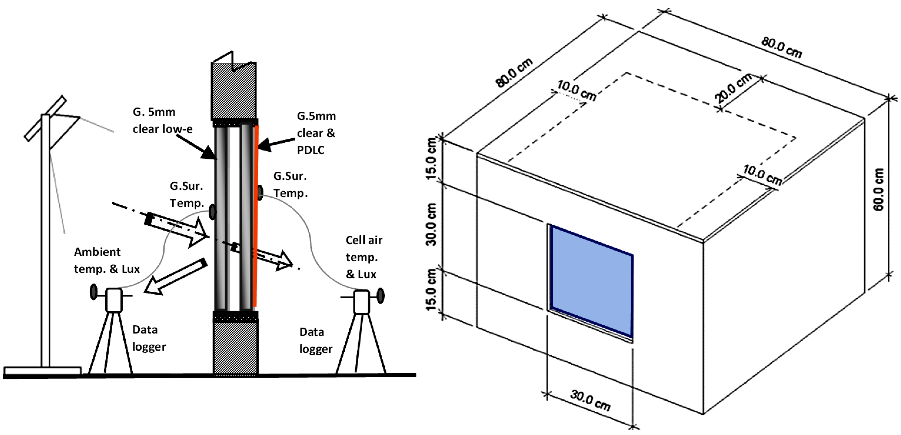
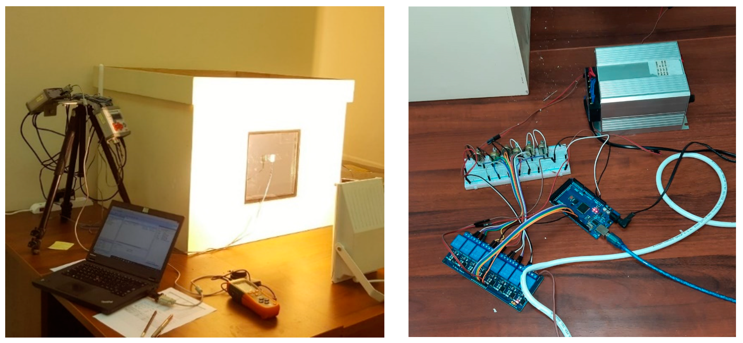
2.1. Test Cell, Glazing System and Instrumentations
2.2. Solar Simulator
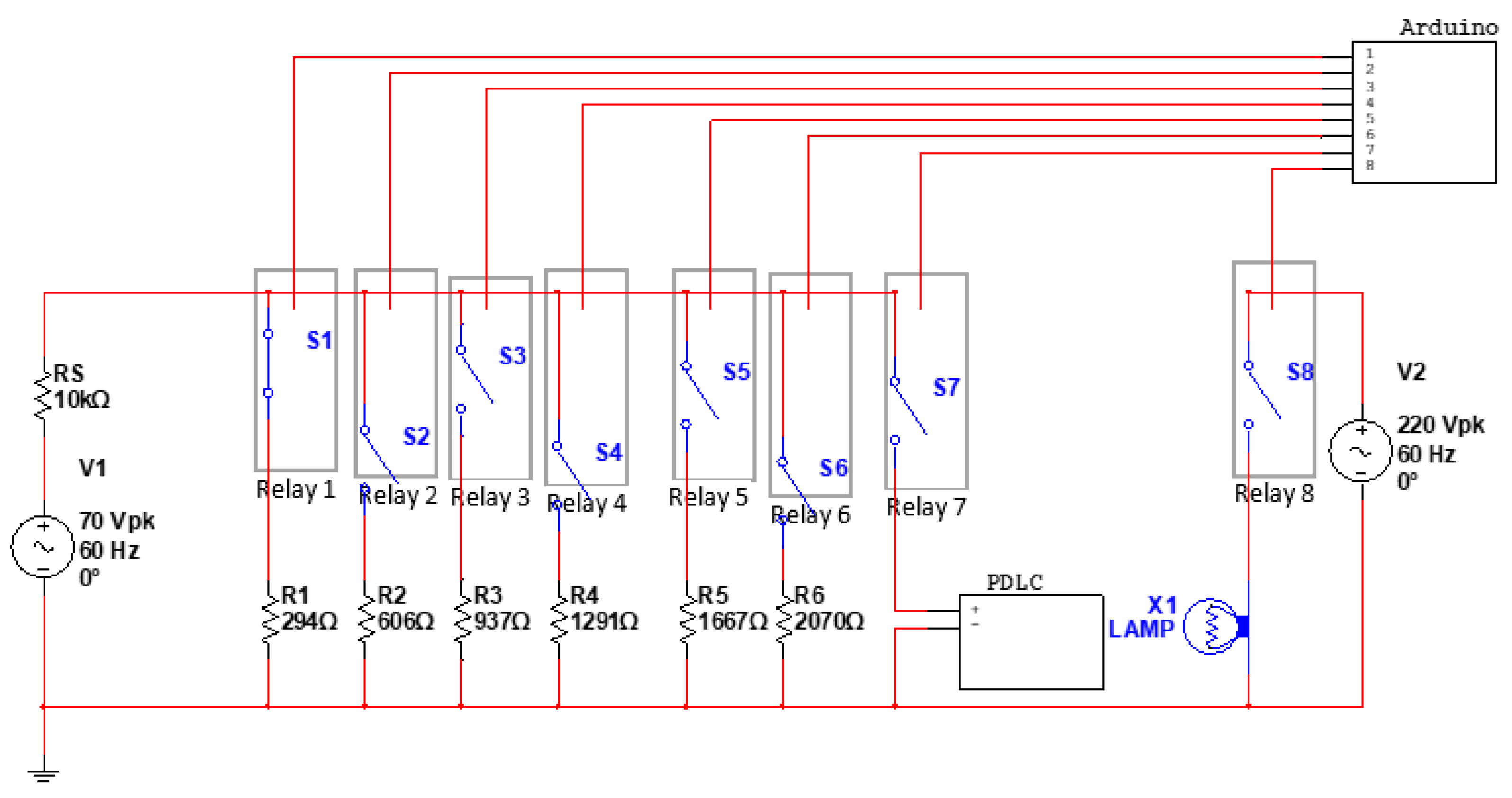
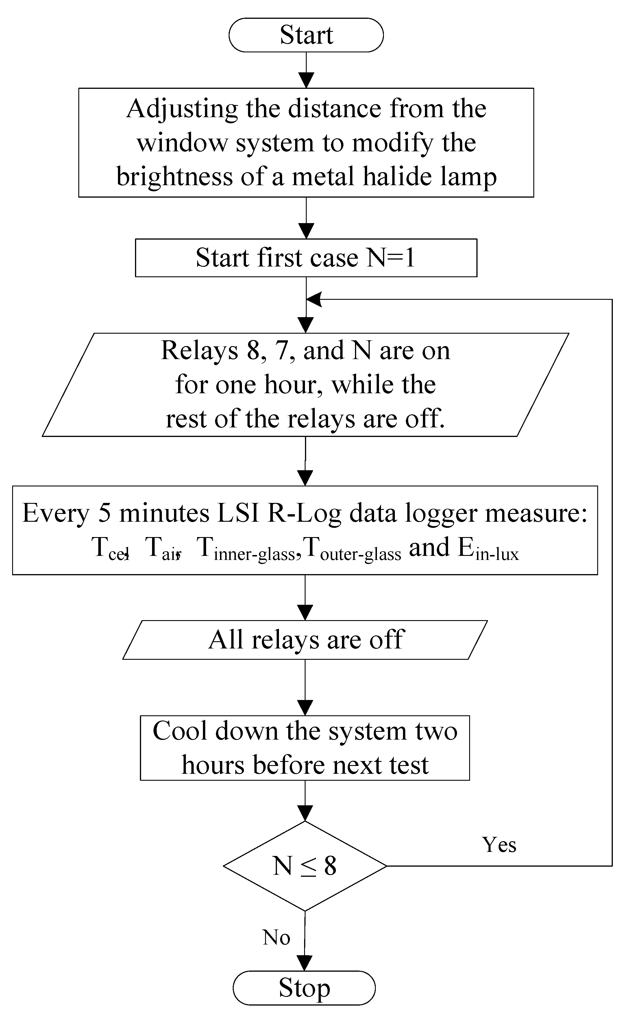
2.3. Dynamic Setpoint Control Operation
- Metal halide lamp brightness could be adjusted by varying the distance from the window system.
- For 60 min, relays 8, 7 and N were on, while the rest of the relays were off.
- All relays were turned off for 120 min to allow the system to cool down before the next test.
- An LSI R-Log data logger was used to measure air temperature inside the test cell Tcel and ambient (lab room) Tair, glass surfaces inner Tinner-glass and outer temperature Touter-glass, and illumination lux inside the test cell Ein-lux.
- Steps 2–4 were repeated six times to complete the six separate transparency situations.
2.4. Double Dynamic Insulated Glazing System, DDIG
3. Results and Discussion
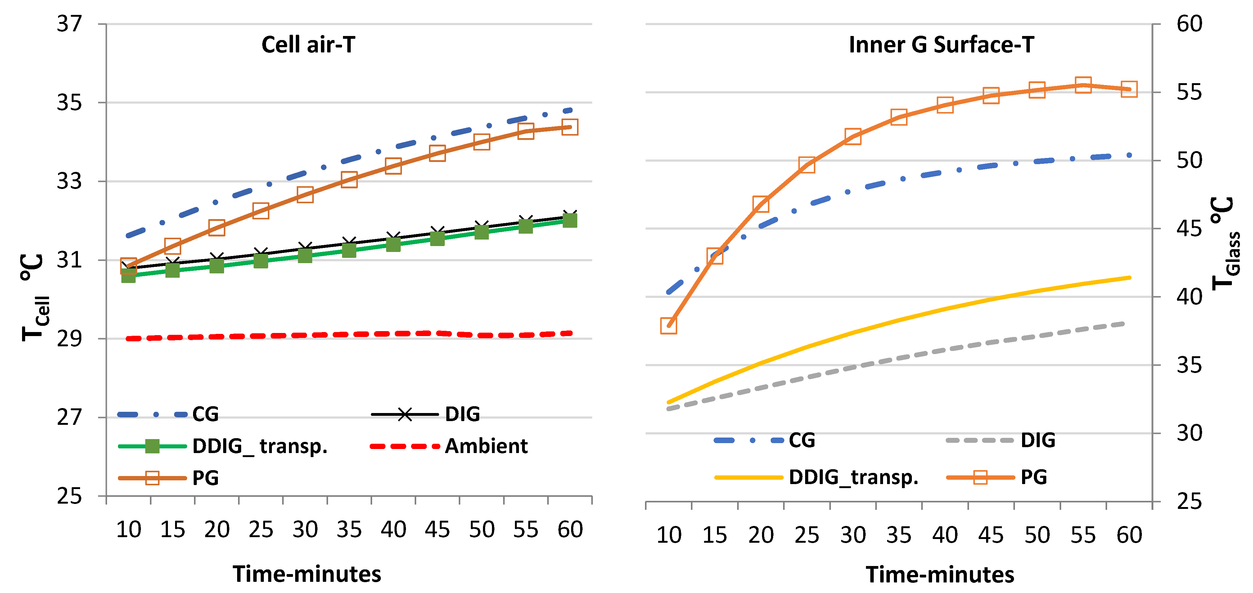
3.1. Comparative Evaluations-Baseline
3.2. Dynamic Transparency of DDIG with Accordance to Dynamics of Solar Radiation
3.2.1. Thermal Performance of Various Transparencies of the DDIG System
- ▪
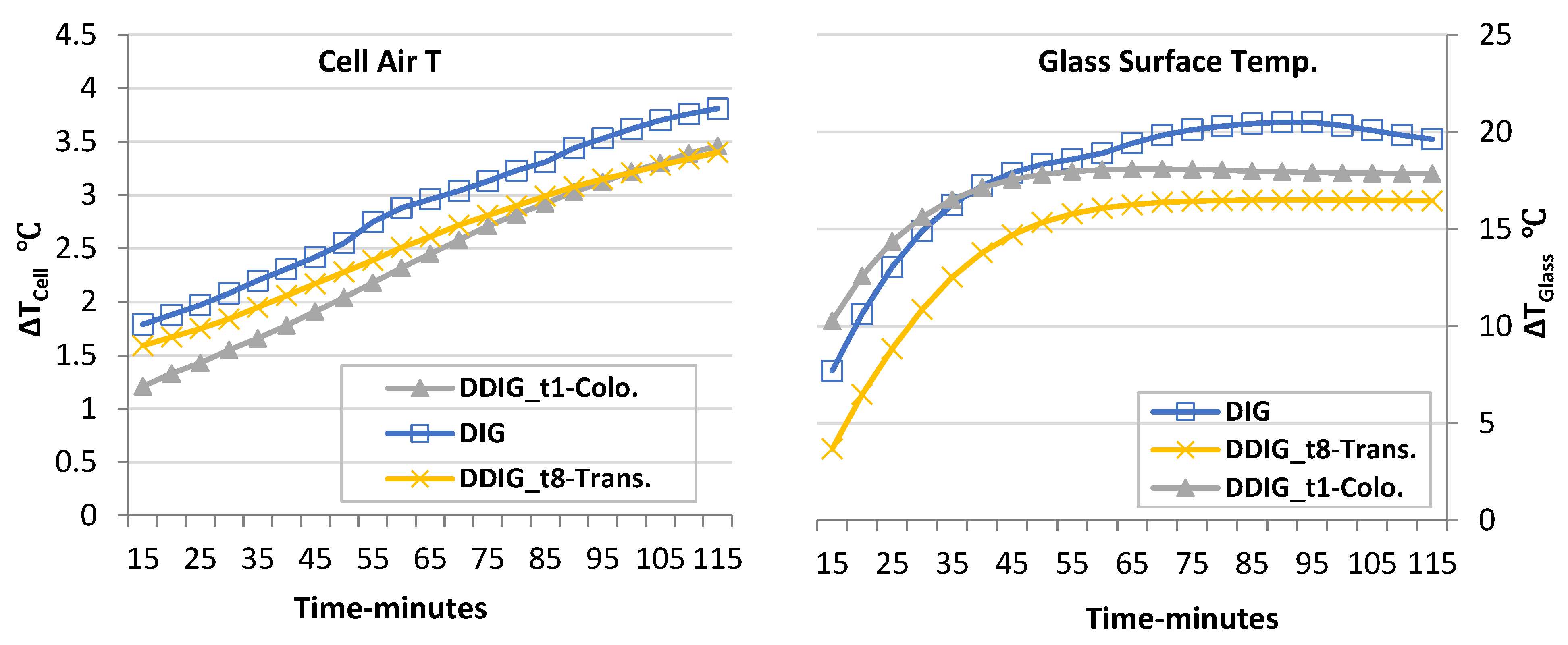
- Under the irradiation of 1000 W/m2 (see row 1 of Table 6), the temperature differences (∆TCell and ∆TGlass) of the DDIG system with eight transparencies (t1 to t8) are illustrated. After 60 min exposure to the sun simulator lamp, the glass surface temperature differences (∆TGlass) varied between 17.3 and 18.8 °C at t8-trans and t1-colo, respectively, corresponding to a gap difference of about 1.5 °C between the two transparencies. Negligible variations were found in the remaining transparencies (from t3 to t6). However, a low-e coat on the inner surface of the outer glass pane reduced the conduction heat gain, which caused a lower temperature of the internal glass. In addition, the coloured state of the PDLC film on the internal glass of the DDIG system reflected a portion of solar irradiance toward the outer glass pane, increasing its surface temperature compared to the surface temperature of the internal glass pane. By contrast, air temperature differences (∆TCell) between the test cell and the ambient environment remained almost the same at all transparencies, with a temperature difference of about 2.7 °C. This was found at t1-colo, marking a temperature difference slightly higher than that found at t8-trans (about 2.5 °C) following 60 min exposure to the solar simulator lamp. The greater this difference, the higher the rate of heat gain. DDIG, in its transparent state at 1000 W/m2, caused an increase in heat gain of about 12% compared with the coloured state. Hence, t1-colo is preferred because of the lower temperature difference between the test cell and the ambient.
- ▪
- Under the irradiation of 800 W/m2 (see row 2 of Table 6), the glass surface temperature differences varied between 15.5 and 17.2 °C at t8-trans and t1-colo, respectively, corresponding to a gap difference of about 1.7 °C between the two transparencies. The temperature variation between the ambient and test cell ranged from 2.1 °C at t1-colo to 2.4 °C at t8-trans, indicating a 12% difference in favour of t1-colo. DDIG performed similarly under high solar intensities of 1000 and 800 W/m2 in both the transparent state and coloured state due to low solar reflection and control in both states.
- ▪
- Under the irradiation of 600 W/m2 (see row 3 of Table 6), the glass surface temperature differences varied between 12.9 and 14.4 °C at t8-trans and t1-colo, respectively, corresponding to a gap difference of about 1.5 °C between the two transparencies. In terms of air temperature variation, the plots show that the differences had a higher gap between t1-colo and t8-trans compared with that at 1000 and 800 W/m2. Given that a lower difference is preferred, t1-colo is more efficient in controlling heat transmission inward. The temperature difference was found to be about 1.9 °C, which was less than the 2.3 °C at t8-trans, indicating a 17.4% difference in favour of t1-coloured.
- ▪
- Under the irradiation of 400 W/m2 (see row 4 of Table 6), the glass surface temperature differences varied between 9.2 and 10.8 °C at t8-trans and t1-colo, respectively, corresponding to a gap difference of about 1.6 °C between the two transparencies. The plots show that the differences between the ambient environment and the test cell had a clear temperature variation between the case of t1-colo and the case of t8-trans. The lower difference was found at t1-colo with a temperature difference of 1.4 °C compared with 1.9 °C at t8-trans, indicating a 20.3% difference in favour of t1-colo.
- ▪
- Under the irradiation of 200 W/m2 (see row 5 of Table 6), the plots show the differences in grading in accordance with the changes in the transparency of DDIG. Eliminating the overlapping curves, the lower air temperature difference between ambient and test cell of about 0.9 °C was found at t1-colo, compared with an air temperature difference of about 1.4 °C at t8-trans following 60 min of exposure. This result indicates a 35.7% difference between the two cases in favour of t1-colo.
3.2.2. Validation of DDIG Thermal Performance of Both Cases: Coloured and Transparent
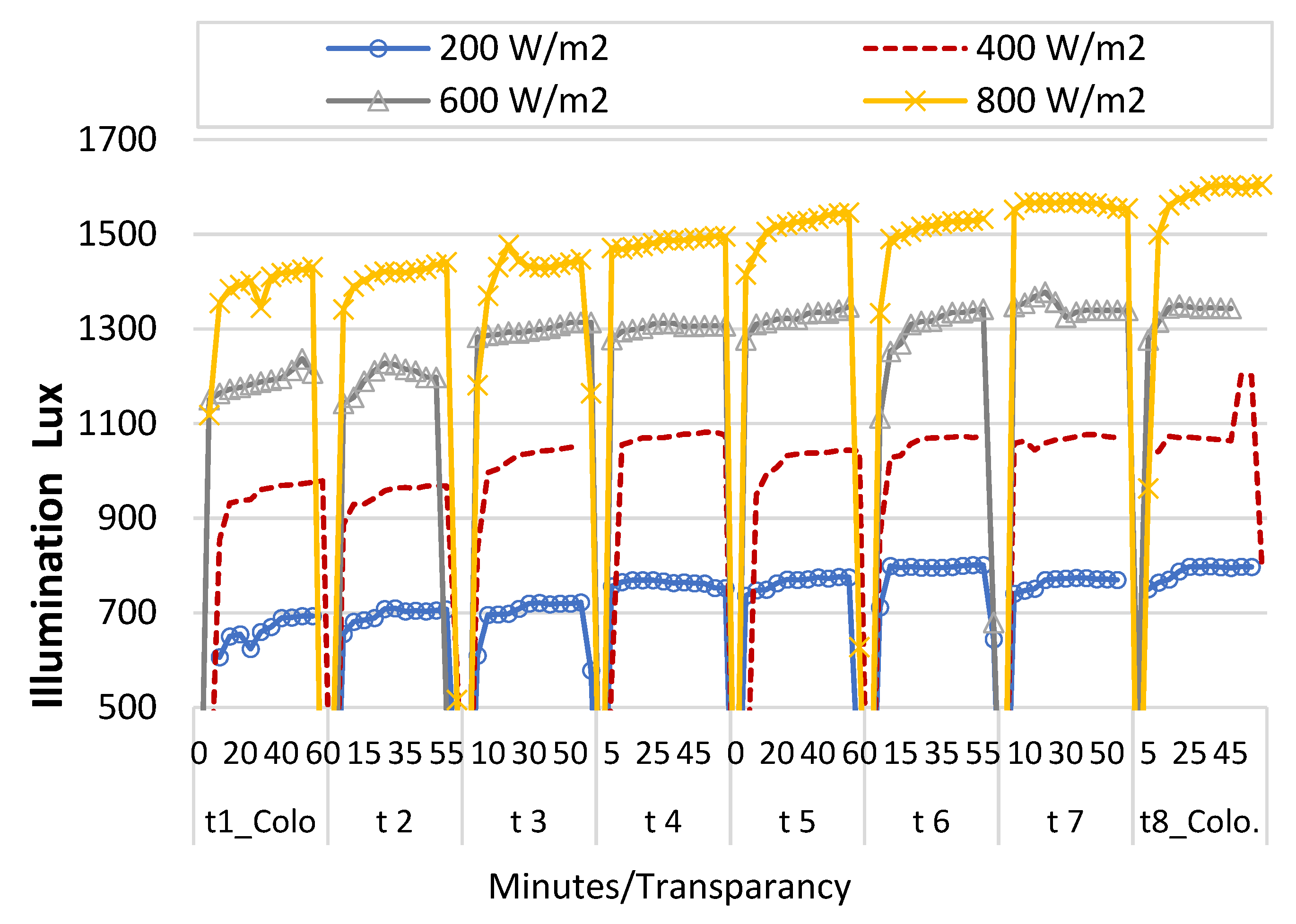
3.3. Lighting Transmission and Illumination Lux with the DDIG System
3.4. Optimum Transparency of the DDIG System for Homes in a Hot Climate
- ▪
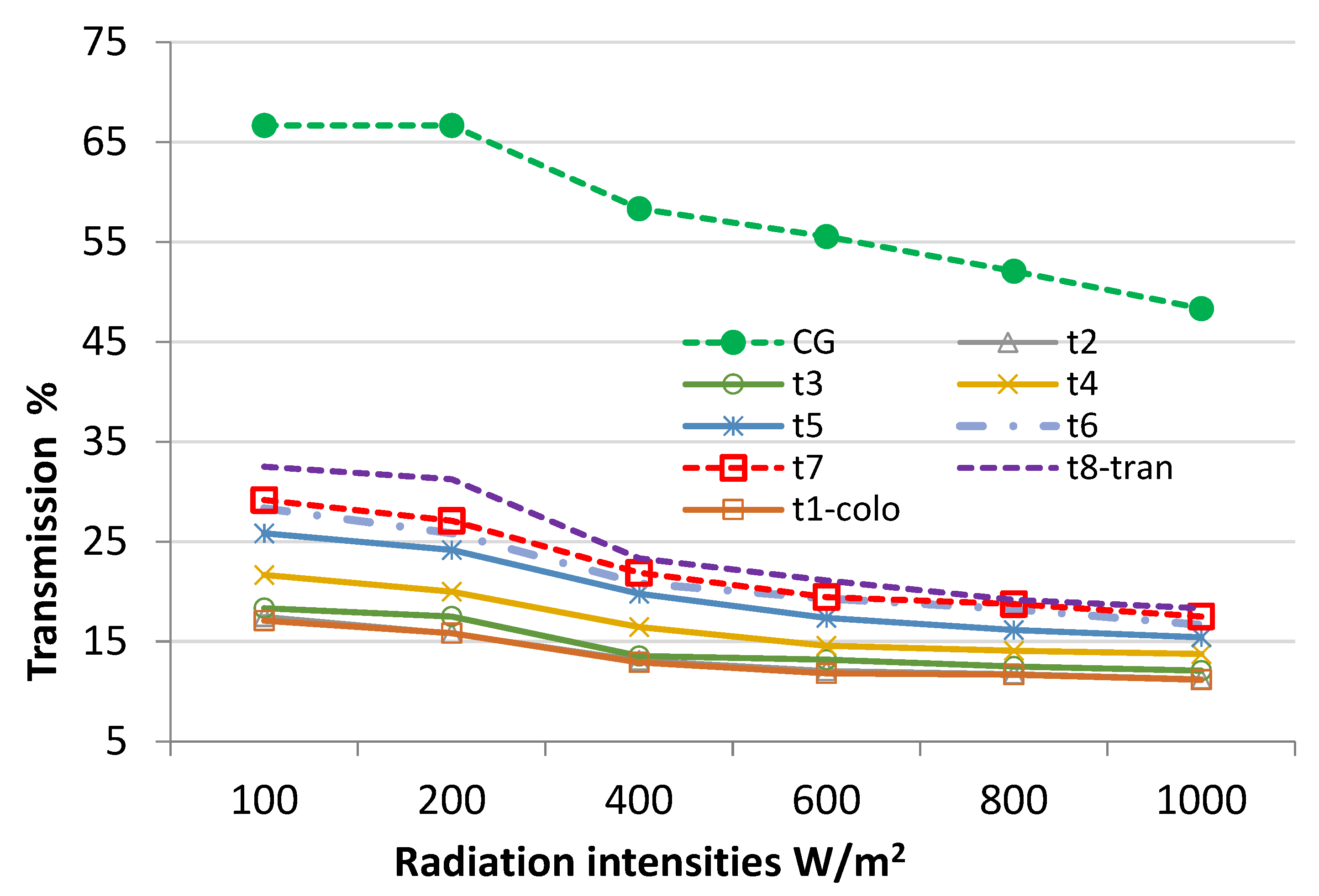
- The setpoint of solar irradiation of (≤100) W/m2 turned the transparency of the DDIG into t1-colo, knowing that the PDLC haze coefficient of t1-coloured was 71.4% and t8 was 6.4% [22]. However, the priority, in this case, was given to privacy protection as indoor lux was higher than outdoor lux (frequently, electrical lighting is switched on in the early morning and early evening).
- ▪
- Under the solar irradiation of 100 < SPI ≤ 200 and 200 < SPI ≤ 400 W/m2, the selected transparency was also t1, which provides thermal reduction as shown in Figure 6. It was also suitable to choose t5 (with an approximate haze coefficient of 34%, considering that t1 was 71.4%). This choice provided enough light and enabled residents to see through from the inside out while still providing privacy protection because the outdoors is brighter.
- ▪
- The t1-coloured state of the system under solar radiation is recommended to be within the range of 400 < SPI ≤ 600 W/m2 with priority given to heat control.
- ▪
- Under high solar irradiation of 600 < SPI ≤ 800 W/m2 and 800 < SPI, the t1-coloured state of the system is recommended for daylight glare control, in addition to its contribution to a slight heat control compared with its transparent state.
- ▪
- The transparency of t8-trans and t7 should be manually switched to provide an outdoor connection as needed.
- ▪
- At night when tenants are inside the home and use electrical lighting, more light was being reflected inside than that coming from outside. Therefore, DDIG-t1-colo is the choice for maximum privacy protection.
3.5. Limitations of the Study
4. Conclusions and Recommendations
4.1. Thermal Performance of the Proposed DDIG Window System
- ▪
- A significant contribution in controlling heat gain indoors was found in DDIG compared with the common translucent glazing of PG, which is mostly used in residential buildings of Najran, Saudi Arabia. A reduction of 2.5 °C inside the test cell occurred when replacing PG with the proposed DDIG system.
- ▪
- An improvement in DDIG’s capability to reduce heat gain was found to be inversely proportional to the intensity of solar radiation, where the efficiency of the DDIG increased as the solar radiation decreased.
- ▪
- At high solar radiation intensities, no significant differences were found between t1-colo and t8-trans. The remaining examined transparencies, particularly t4, t5 and t6, have no significant variation in controlling the heat gain to the test cell space under all solar radiation intensities. In terms of glazing surface temperature, the inner glass surface temperature of all transparencies of DDIG and under different solar radiation intensities remained lower than that of the outer one, causing lower heat energy transmission inward.
4.2. Optimum Transparencies with Solar Set Points
- ▪
- The t1-coloured state of the system is recommended for solar irradiations within the range of 100 W/m2 for privacy protection, as well as for solar irradiations from 400 W/m2 to 600 W/m2 for heat control. At night when electrical lighting is switched on, DDIG-t1-colo is also recommended for maximum privacy protection.
- ▪
- The transparency of t5 is recommended for solar irradiations of 200 W/m2, which enables some privacy protection and an outdoor connection.
- ▪
- The t1-coloured state is recommended for high solar irradiations of 800 W/m2 and above, which enables solar heat control as well as daylight glare control.
- ▪
- The transparency of t8-trans and t7 should be manually switched to provide an outdoor connection as needed.
4.3. In Terms of Indoor Illuminance
Author Contributions
Funding
Institutional Review Board Statement
Informed Consent Statement
Data Availability Statement
Conflicts of Interest
References
- Kaasalainen, T.; Mäkinen, A.; Lehtinen, T.; Moisio, M.; Vinha, J. Architectural window design and energy efficiency: Impacts on heating, cooling and lighting needs in Finnish climates. J. Build. Eng. 2020, 27, 100996. [Google Scholar] [CrossRef]
- Acosta, I.; Campano, M.Á.; Molina, J.F. Window design in architecture: Analysis of energy savings for lighting and visual comfort in residential spaces. Appl. Energy 2016, 168, 493–506. [Google Scholar] [CrossRef]
- Wu, H.; Wang, D.; Liu, Y.; Wang, Y. Study on the effect of building envelope on cooling load and life-cycle cost in low latitude and hot-humid climate. Procedia Eng. 2017, 205, 975–982. [Google Scholar] [CrossRef]
- Lu, S.; Li, Z.; Zhao, Q. Thermal Process of Windows in Hot Summer and Cold Winter Climate. Procedia Eng. 2015, 121, 1788–1794. [Google Scholar] [CrossRef]
- Santolini, E.; Pulvirenti, B.; Guidorzi, P.; Bovo, M.; Torreggiani, D.; Tassinari, P. Analysis of the effects of shading screens on the microclimate of greenhouses and glass facade buildings. Build. Environ. 2022, 211, 108691. [Google Scholar] [CrossRef]
- Ye, Y.; Xu, P.; Mao, J.; Ji, Y. Experimental study on the effectiveness of internal shading devices. Energy Build. 2016, 111, 154–163. [Google Scholar] [CrossRef]
- Qahtan, A.M. An Empirical Study on the Use of Water Film in Glazed Buildings to Reduce Solar Radiation Transmittance in the Tropics. J. Green Build. 2015, 10, 141–160. [Google Scholar] [CrossRef]
- Kou, R.; Zhong, Y.; Kim, J.; Wang, Q.; Wang, M.; Chen, R.; Qiao, Y. Elevating low-emissivity film for lower thermal transmittance. Energy Build. 2019, 193, 69–77. [Google Scholar] [CrossRef]
- Al-Tamimi, N.; Qahtan, A.; Abuelzein, O. Rear zone for energy efficiency in large mosques in Saudi Arabia. Energy Build. 2020, 223, 110148. [Google Scholar] [CrossRef]
- Tuchinda, C.; Srivannaboon, S.; Lim, H.W. Photoprotection by window glass, automobile glass, and sunglasses. J. Am. Acad. Dermatol. 2006, 54, 845–854. [Google Scholar] [CrossRef] [PubMed]
- Li, D.H.W.; Tsang, E.K.W. An analysis of daylighting performance for office buildings in Hong Kong. Build. Environ. 2008, 43, 1446–1458. [Google Scholar] [CrossRef]
- Kumar, G.K.; Babu, T.P.A. Study of Various Glass Materials to Provide Adequate Day Lighting in Office Buildings of Warm and Humid Climatic Zone in India. Energy Procedia 2017, 109, 181–189. [Google Scholar] [CrossRef]
- Schaefer, C.; Bräuer, G.; Szczyrbowski, J. Low emissivity coatings on architectural glass. Surf. Coat. Technol. 1997, 93, 37–45. [Google Scholar] [CrossRef]
- Somasundaram, S.; Thangavelu, S.R.; Chong, A. Effect of Existing Façade’s Construction and Orientation on the Performance of Low-E-Based Retrofit Double Glazing in Tropical Climate. Energies 2020, 13, 2016. [Google Scholar] [CrossRef]
- Jelle, B.P.; Kalnæs, S.E.; Gao, T. Low-emissivity materials for building applications: A state-of-the-art review and future research perspectives. Energy Build. 2015, 96, 329–356. [Google Scholar] [CrossRef]
- KiranKumar, G.; Saboor, S.; Babu, T.P.A. Investigation of Various Low Emissivity Glass Materials for Green Energy Building Construction in Indian Climatic Zones. Mater. Today Proc. 2017, 4, 8052–8058. [Google Scholar] [CrossRef]
- Kim, J.; Kent, M.; Kral, K.; Dogan, T. Seemo: A new tool for early design window view satisfaction evaluation in residential buildings. Build. Environ. 2022, 214, 108909. [Google Scholar] [CrossRef]
- Ghosh, A.; Norton, B.; Mallick, T.K. Daylight characteristics of a polymer dispersed liquid crystal switchable glazing. Sol. Energy Mater. Sol. Cells 2018, 174, 572–576. [Google Scholar] [CrossRef]
- Oh, M.; Park, J. Evaluation of building energy and daylight performance according to applying electrochromic and pdcl (polymer dispersed liquid crystal) to office building in South Korea. Int. J. Sustain. Build. Technol. Urban Dev. 2019, 227–240. [Google Scholar] [CrossRef]
- Shaik, S.; Nundy, S.; Maduru, V.R.; Ghosh, A.; Afzal, A. Polymer dispersed liquid crystal retrofitted smart switchable glazing: Energy saving, diurnal illumination, and CO2 mitigation prospective. J. Clean. Prod. 2022, 350, 131444. [Google Scholar] [CrossRef]
- Scorpio, M.; Ciampi, G.; Rosato, A.; Maffei, L.; Masullo, M.; Almeida, M.; Sibilio, S. Electric-driven windows for historical buildings retrofit: Energy and visual sensitivity analysis for different control logics. J. Build. Eng. 2020, 31, 101398. [Google Scholar] [CrossRef]
- Hemaida, A.; Ghosh, A.; Sundaram, S.; Mallick, T.K. Evaluation of thermal performance for a smart switchable adaptive polymer dispersed liquid crystal (PDLC) glazing. Sol. Energy 2020, 195, 185–193. [Google Scholar] [CrossRef]
- Ghosh, A.; Norton, B. Durability of switching behaviour after outdoor exposure for a suspended particle device switchable glazing. Sol. Energy Mater. Sol. Cells 2017, 163, 178–184. [Google Scholar] [CrossRef]
- Hemaida, A.; Ghosh, A.; Sundaram, S.; Mallick, T.K. Simulation study for a switchable adaptive polymer dispersed liquid crystal smart window for two climate zones (Riyadh and London). Energy Build. 2021, 251, 111381. [Google Scholar] [CrossRef]
- Ghosh, A.; Mallick, T.K. Evaluation of optical properties and protection factors of a PDLC switchable glazing for low energy building integration. Sol. Energy Mater. Sol. Cells 2018, 176, 391–396. [Google Scholar] [CrossRef]
- Oh, M.; Lee, C.; Park, J.; Lee, K.; Tae, S. Evaluation of Energy and Daylight Performance of Old Office Buildings in South Korea with Curtain Walls Remodeled Using Polymer Dispersed Liquid Crystal (PDLC) Films. Energies 2019, 12, 3679. [Google Scholar] [CrossRef]
- Malek, M.R.A.; Aziz, N.A.A.; Alelyani, S.; Mohana, M.; Baharudin, F.N.A.; Ibrahim, Z. Comfort and energy consumption optimization in smart homes using bat algorithm with inertia weight. J. Build. Eng. 2022, 47, 103848. [Google Scholar] [CrossRef]
- del Rio, D.D.F.; Sovacool, B.K.; Bergman, N.; Makuch, K.E. Critically reviewing smart home technology applications and business models in Europe. Energy Policy 2020, 144, 111631. [Google Scholar] [CrossRef]
- Chen, Q. Ventilation performance prediction for buildings: A method overview and recent applications. Build. Environ. 2009, 44, 848–858. [Google Scholar] [CrossRef]
- Lirola, J.M.; Castañeda, E.; Lauret, B.; Khayet, M. A review on experimental research using scale models for buildings: Application and methodologies. Energy Build. 2017, 142, 72–110. [Google Scholar] [CrossRef]
- Alwetaishi, M. Impact of glazing to wall ratio in various climatic regions: A case study. J. King Saud Univ. Eng. Sci. 2019, 31, 6–18. [Google Scholar] [CrossRef]
- Tawfik, M.; Tonnellier, X.; Sansom, C. Light source selection for a solar simulator for thermal applications: A review. Renew. Sustain. Energy Rev. 2018, 90, 802–813. [Google Scholar] [CrossRef]
- Wang, W.; Laumert, B. Simulate a ‘sun’for solar research: A literature review of solar simulator technology. Ind. Appl. 2014, 50, 3055–3064. [Google Scholar]
- Colarossi, D.; Tagliolini, E.; Principi, P.; Fioretti, R. Design and Validation of an Adjustable Large-Scale Solar Simulator. Appl. Sci. 2021, 11, 1964. [Google Scholar] [CrossRef]
- Michael, P.R.; Johnston, D.E.; Moreno, W. A conversion guide: Solar irradiance and lux illuminance. J. Meas. Eng. 2020, 8, 153–166. [Google Scholar] [CrossRef]
- Zell, E.; Gasim, S.; Wilcox, S.; Katamoura, S.; Stoffel, T.; Shibli, H.; Engel-Cox, J.; Al Subie, M. Assessment of solar radiation resources in Saudi Arabia. Sol. Energy 2015, 119, 422–438. [Google Scholar] [CrossRef]
- Sobek, S.; Werle, S. Comparative review of artificial light sources for solar-thermal biomass conversion research applications. Ecol. Chem. Eng. S 2019, 26, 443–453. [Google Scholar] [CrossRef]


| Study | Glazing System | Coloured | Transparent | ||||||
|---|---|---|---|---|---|---|---|---|---|
| Solar Transmittance | Visible light Transmittance | Solar Transmittance | Visible Light Transmittance | ||||||
| Hemaida et al. & Ghosh and Mallick [24,25] | Single G. | 23% | 27% | 41% | 71% | ||||
| A. Hemaida et al. [22] | Single G. | 42% | 44% | 62% | 79% | ||||
| M. Oh and J. Park [19] | Double G. | 22% | 32% | 25% | 37% | ||||
| M. Oh and J. Park [19] | Single G. | Front | back | Front | back | Front | back | Front | back |
| 23% | 23% | 39% | 39% | 27% | 27% | 46% | 46% | ||
| Instruments | Manufacturer | Technical Data | Resolution | |
|---|---|---|---|---|
| Two R-Log, data loggers | Surface temp. | LSI | −40 to +80 °C | ±0.01 °C |
| Ambient temp. | −40 to +80 °C | ±0.01 °C | ||
| Lux | 0 to 25,000 lux | ±3 lux | ||
| Extech HD450-lux portable | Extech Instruments | 0 to 400,000 lux | ±0.1 lux | |
| Fluke Infrared Thermometer | Fluke Instruments | −30 to 900 °C | ±1.1 °C | |
| BH1750FVI sensor | Rohm Semiconductor | 0 to 100,000 lux | ±1.2 lux | |
| Cases | 1 | 2 | 3 | 4 | 5 | 6 | 7 | 8 |
|---|---|---|---|---|---|---|---|---|
| Transparency | t1 | t2 | t3 | t4 | t5 | t6 | t7 | t8 |
| Voltage | 0 | 2 | 4 | 6 | 8 | 10 | 12 | 14 |
| RL From Equation (4) | 120K | 294 | 606 | 937 | 1290 | 1666 | 2068 | 2500 |
| Rcase From Equation (2) | ∞ | R1 294 | R2 606 | R3 937 | R4 1291 | R5 1667 | R6 2070 | R7 2553 |
| t1-Colo | t2 | t3 | t4 | P.G. |
 |  |  |  |  |
| t5 | t6 | t7 | t8-Trans | C.G. |
 |  |  |  |  |
| Experiments Variables | Symbol | Test Level | ||||||||
|---|---|---|---|---|---|---|---|---|---|---|
| 1 | 2 | 3 | 4 | 5 | 6 | 7 | 8 | |||
| Operating variables | PDLC Transparency | t | t1 colo | t2 | t3 | t4 | t5 | t6 | t7 | t8 Trans |
| Solar irradiance (W/m2) | Sun | 100, 200, 400, 600, 800 & 1000 W/m2 | ||||||||
| Response variables | Glass surface temperature | TGlass | ∆ Glass temperature (∆TGlass) | |||||||
| Test cell temperature | TCell | ∆ air temperature (∆TCell) | ||||||||
| Test cell illumination | Lux | Illumination Lux | ||||||||
| Sub-Response | Privacy protection | -- | (Y/N) | |||||||
| Dynamic Setpoint Control | ∆ Surface-Temperature | ∆ Cell-Temperature |
|---|---|---|
| At 1000 W/m2 | 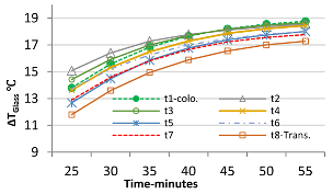 | 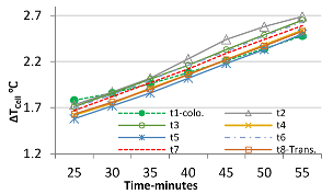 |
| At 800 W/m2 | 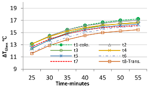 |  |
| At 600 W/m2 |  | 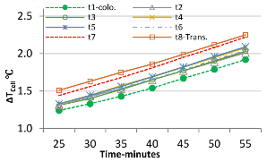 |
| At 400 W/m2 |  | 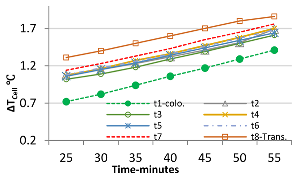 |
| At 200 W/m2 | 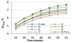 |  |
| Set Points W/m2 Summer | Based on Measured Variables | Proposed DDIG Transparency | Privacy | |
|---|---|---|---|---|
| Heat Control | Daylighting | |||
| SPI ≤ 100 | na | na | t1 | t1 |
| 100 < SPI ≤ 200 | t1 | t1 to t8 | t5 | t1 to t4 |
| 200 < SPI ≤ 400 | t1 | t1 to t8 | t5 | t1 to t4 |
| 400 < SPI ≤ 600 | t1 to t6 | t1 to t8 | t1 | t1 to t4 |
| 600 < SPI ≤ 800 | t1 to t8 | t1 to t8 | t1 | t1 to t4 |
| 800 < SPI | t1 to t8 | t1 to t8 | t1 | t1 to t4 |
Publisher’s Note: MDPI stays neutral with regard to jurisdictional claims in published maps and institutional affiliations. |
© 2022 by the authors. Licensee MDPI, Basel, Switzerland. This article is an open access article distributed under the terms and conditions of the Creative Commons Attribution (CC BY) license (https://creativecommons.org/licenses/by/4.0/).
Share and Cite
Qahtan, A.M.; Almawgani, A.H.M. Experimental Evaluation of Thermal and Lighting Performance Using Double Dynamic Insulated Glazing. Buildings 2022, 12, 1249. https://doi.org/10.3390/buildings12081249
Qahtan AM, Almawgani AHM. Experimental Evaluation of Thermal and Lighting Performance Using Double Dynamic Insulated Glazing. Buildings. 2022; 12(8):1249. https://doi.org/10.3390/buildings12081249
Chicago/Turabian StyleQahtan, Abdultawab M., and Abdulkarem H. M. Almawgani. 2022. "Experimental Evaluation of Thermal and Lighting Performance Using Double Dynamic Insulated Glazing" Buildings 12, no. 8: 1249. https://doi.org/10.3390/buildings12081249
APA StyleQahtan, A. M., & Almawgani, A. H. M. (2022). Experimental Evaluation of Thermal and Lighting Performance Using Double Dynamic Insulated Glazing. Buildings, 12(8), 1249. https://doi.org/10.3390/buildings12081249