Abstract
To reduce the impact of poor field connection on structural safety in prefabricated concrete structures, a new kind of prefabricated reinforced concrete structure—an FTPC (fault-tolerant prefabricated concrete) structure based on the fault-tolerant design concept—was proposed and studied in this paper. The horizontal load-bearing units of an FTPC structure are fully prefabricated or semi-prefabricated slabs. The vertical load-bearing units are formed by four types of prefabricated cantilever components. Prefabricated cantilever components are horizontally connected by welded connection and vertically connected by a specific connection method using steel tubes and cast-in-place concrete. A mathematical sampling method can be used to select several welded connection nodes as disconnected nodes to consider the actual weld quality. Enveloping design can be carried out to obtain the final design results of each cantilever component, which can realize the fault-tolerant design and better ensure the structure safety. Finite element analysis was carried out for a two-story villa as an example to verify the feasibility and rationality of an FTPC structure. Study results show that an FTPC structure can meet the requirements of safety and applicability. Moreover, it has the advantages of a flexible arrangement of load-bearing components, a clear force transmission mechanism, and a moderate component volume.
1. Introduction
In order to promote the development of green construction, mitigate the negative impacts on the environment (i.e., noise, dust, site disturbance, etc.), reduce wet work and labor costs, and save resources and energy, prefabricated technologies are being vigorously promoted for reinforced concrete structures []. Compared with cast-in-place concrete structures, prefabricated reinforced concrete structures are characterized by off-prefabrication and field connections [], which can better ensure the quality of prefabricated components [,,,].
The load-bearing components in prefabricated concrete structures include horizontal and vertical load-bearing components: shear walls and columns serve as vertical load-bearing components, beams and floor slabs serve as horizontal load-bearing components. The production of prefabricated components is completed in the factory, which can ensure the quality. The connection forms and field connection quality of components have great impacts on the overall safety of the structure.
For the horizontal load-bearing components in prefabricated concrete structures, a semi-prefabricated beam (prefabricated in the lower part and post-cast in the upper part) and a truss reinforcement composite concrete slab is a commonly used combination. After the hoisting of components is completed, the components are connected with reinforcement bars. Then, the concrete should be poured into the cast-in-place layer to achieve the equivalent cast-in-place connection of the components. The workload of pouring concrete on site is large, but the quality of the connection is good.
For the vertical load-bearing components, if shear walls are employed, they are usually large, prefabricated wallboards with sandwich construction. The reinforced concrete surface layers and lightweight thermal insulation inner core of the prefabricated wallboards are connected as a whole by reinforcement bars, so that the inner core and surface layers are working cooperatively, forming a wall with good integrity. In this way, the sandwich wall can meet the requirements of load and energy saving at the same time. The connection methods between shear walls mainly include dry methods without post-cast concrete (i.e., bolt connection [,], prestressed connection [,], tenon connection [,], etc.) and wet methods with post-cast concrete [,]. For bolt connection methods, connectors should be reserved on the prefabricated wall, and bolts are used to connect the walls on site. Although the operation is simple, the force transmission depends entirely on the bolt, leading to poor bearing capacity. For prestressed connections, prestressed tendons should be passed through the tunnel routed in walls and tensioned. After the prestressed tendons are fixed, the tunnel grouting should be completed. By prestressed connections, reliable connections are realized, but the operation is cumbersome and expensive. For tenon connections, grooves and protrusions are placed on the sides of the wall, and tenon boards are used to connect adjacent walls, which requires a higher construction quality. In wet connections, the post-cast zone is set to realize the connection of walls. Though the integrity and seismic performance of this equivalent cast-in-place connection are good, the construction is slow, and the workload is high. In addition, to the best of our knowledge, due to the large volume and weight of walls, the wall bearing structures face transportation and hoisting challenges.
If columns are employed as the vertical load-bearing components, the connection methods of columns to beams can also be divided into dry methods without post-cast concrete and wet methods with post-cast concrete. The dry methods usually include the bolted or welded connection method [,], prestressed connection method [,], etc. Both bolted and welded connections are completed on site with the requirement of connectors being placed on the components, while the actual quality of onsite construction is usually difficult to ensure. For the prestressed connection, the precast prestressed efficiently fabricated frame—PPEFF system [] (i.e., prestressed tendons are passed through the beam–column joint core area and tensioned at the middle of the beam to make a reliable connection between beam and column)—is a typical application in China. However, the prestressed connection methods are usually complicated and costly. For the wet methods, prefabricated beams can be connected to prefabricated columns by post-cast joint area []: after the connection of the reserved reinforcement bars in the beam–column joint area is completed, the concrete is poured in the joint area to realize equivalent cast-in-place connection. Alternatively, the joint area can be prefabricated with the post-cast strip set on the beam or column for connection [,]. In either case, complicated reinforcement connection processes such as sleeve grouting connection or slurry anchor connection are often used [,,,,]. During sleeve grouting connections, the reserved reinforcement bars of components are inserted into the embedded sleeves. Then the grouting material should be poured into the sleeve through the grouting hole, leading to perfect connections. During slurry anchor connections, the corrugated pipes are buried in the component, and then the reinforcement bars are inserted into the corrugated pipes. Finally, the grouting material should be poured into the corrugated pipes.
In summary, the existing connection methods for load-bearing components in prefabricated concrete structures are weak in the field connection effect, which may become the hidden danger to structural safety. Although some connection methods can reach good connection quality, the operations are complicated, and the cost is high. How to deal with the weak connections between components can be seen as an important obstacle for the promotion and application of prefabricated concrete structures.
Referencing from the advantages of existing technologies, a new kind of fabricated concrete structure—an FTPC (fault-tolerant prefabricated concrete) structure based on the fault-tolerant design concept—will be proposed in this paper. For the FTPC structure with the employment of dry and wet connection technologies, quality risks of field connections are considered proactively. The vertical equivalent cast-in-place connection of cantilever bearing components can be realized through steel tubes and post-cast concrete, and no formwork is required during concrete pouring. During the horizontal connection of cantilever load-bearing components, the requirements for the welding quality of the connecting steel are not high. The innovatively designed components and their combinations can also meet the needs of diverse house types. The combination of the mathematical method considering the quality of welded joints and the multimodel analysis makes the structural analysis more reasonable. How to balance the design of each component and the combination of all types of components, how to balance efficiency and safety, and how to reduce the whole process cost have been preconceived. The division and connection mode of basic components, the key design points of an FTPC structure will be proposed and an example analysis will be provided to promote its application and popularization.
2. Introduction of FTPC Structure
2.1. Division and Connection Mode of Basic Components
The FTPC structure used in this study can be divided into horizontal load-bearing units and vertical load-bearing units.
The horizontal load-bearing units are fully prefabricated or semi-prefabricated slabs, which can be designed as one-way force transmission or two-way force transmission slabs. The load on the one-way slab is conducted by opposite sides, while the load on the two-way slabs is conducted by four sides, as shown in Figure 1. At the same time, every side of the two-way slabs needs reserved reinforcement bars and post-cast strip for the connection of slabs, while the one-way slabs are only provided with reserved reinforcement bars and post-cast strips on the short sides. Due to the relatively complex structure and force transmission path of the two-way force transmission slabs, one-way force transmission slabs are more recommended in general. During the connection of slabs, the reserved reinforcement bars should be connected, and then concrete is poured into the post-cast strip.
Figure 1.
Schematic diagram of floor slab: (a) one-way slab, (b) two-way slab.
The vertical load-bearing units are formed by four types of prefabricated cantilever components that are made of reinforced concrete and innovatively designed: standard H-shaped components, corner L-shaped components, T-shaped components, and cross-shaped components, as shown in Figure 2a–d, respectively.
Figure 2.
Schematic diagram of four types of prefabricated cantilever components: (a) standard H-shaped component, (b) corner L-shaped component, (c) T-shaped component, and (d) cross-shaped component.
Each basic prefabricated cantilever component includes the upper horizontal part (solid rectangle section denoted as b1 × h1 and the cantilever length is denoted as L), the lower horizontal parts (solid rectangle section denoted as b2 × h2 and the cantilever length is also denoted as L), and the vertical part (hollow rectangle section, the outer size is denoted as b3 × h3, the inner size is denoted as b4 × h4, and the height is denoted as H). Steel plate is embedded at the outer end of the horizontal part as a connector (Figure 3a).
Figure 3.
Horizontal connection diagrams of prefabricated cantilever components: (a) schematic of steel plate connector and (b) schematic of welding connection.
On a floor, the corner L-shaped components should be arranged at the corners of external walls, T-shaped components and cross-shaped components should be arranged at the intersection of walls, while standard H-shaped components should be arranged at the rest of the walls. The adjacent components on the same floor are connected by the welding of steel plates (welding all around the steel plates), as shown in Figure 3b. Through this connection method, the prefabricated cantilever components on the same floor can form a vertical load-bearing unit (Figure 4).
Figure 4.
Schematic diagram of a vertical load-bearing unit.
The construction of the vertical load-bearing unit on the first floor should be followed by the construction of the horizontal load-bearing unit (floor slabs) on the second floor. During this construction process, holes with the same projection position and size (b4 × h4) as the hollow part of the vertical part in each prefabricated cantilever component should be reserved. Subsequently, the prefabricated cantilever components on the second floor will be hoisted to form a new vertical load-bearing unit. The vertical part of each prefabricated cantilever component on the first and second floor should be aligned up and down.
The above steps can be repeated until the construction of the horizontal load-bearing unit and the vertical load-bearing unit on the top floor is completed. It should be stressed that vertical part of each prefabricated cantilever component on the adjacent floors should be aligned up and down.
For each vertical hole passing through the slabs and vertical parts of the prefabricated cantilever components, a hollow steel tube with the external size smaller than b4 × h4 should be put in. If a square steel tube is used, the external size can be denoted as b5 × h5. The space between the outer edge of the hollow steel tube and the inner edge of the vertical hollow part should then be filled with post-cast expansive concrete. In this way, effective connection between the vertical and horizontal load-bearing units of each floor can be realized (Figure 5) and the construction of the overall superstructure can be completed. The final section form of the vertical part of each prefabricated cantilever components is shown as Figure 6.
Figure 5.
Schematic diagram of the connection between horizontal and vertical load-bearing units.
Figure 6.
Sectional diagram of vertical part of prefabricated cantilever component.
In summary, the vertical part of the cantilevered component includes the prefabricated reinforcement concrete, steel tube, and post-cast expansive concrete: prefabricated reinforcement concrete is fabricated in the factory together with horizontal parts; the steel tube and post-cast concrete are used for vertical connections of components on-site. By using steel tubes through the upper and lower floor and post-cast concrete, the effective vertical connections of components are achieved. Compared with traditional connection modes, this method eliminates the need for reinforcement bar connections and formwork when pouring concrete.
The foundation can employ the form of a thick reinforced concrete slab with two-way steel mesh inside. Hollow steel tubes with the inner section size as b4 × h4, which is bigger than steel tubes in the superstructure, should be buried in the foundation. Therefore, steel tubes from the superstructure can insert into the bigger steel tubes buried in the foundation. The space between these two kinds of steel tubes should also be filled with post-cast expansive concrete to realize the effective connection between the superstructure and foundation (Figure 7).
Figure 7.
Schematic diagram of the connection between the foundation and the bottom vertical load-bearing unit.
2.2. Features of FTPC Structure
According to the division and connection mode of basic components, the main features of an FTPC structure can be summarized as below:
- (1)
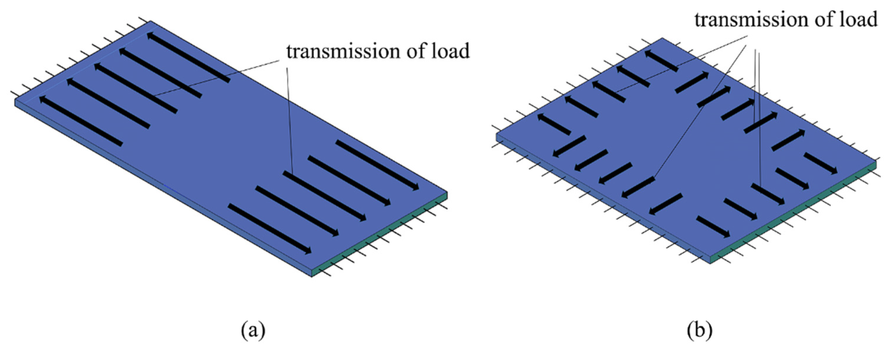
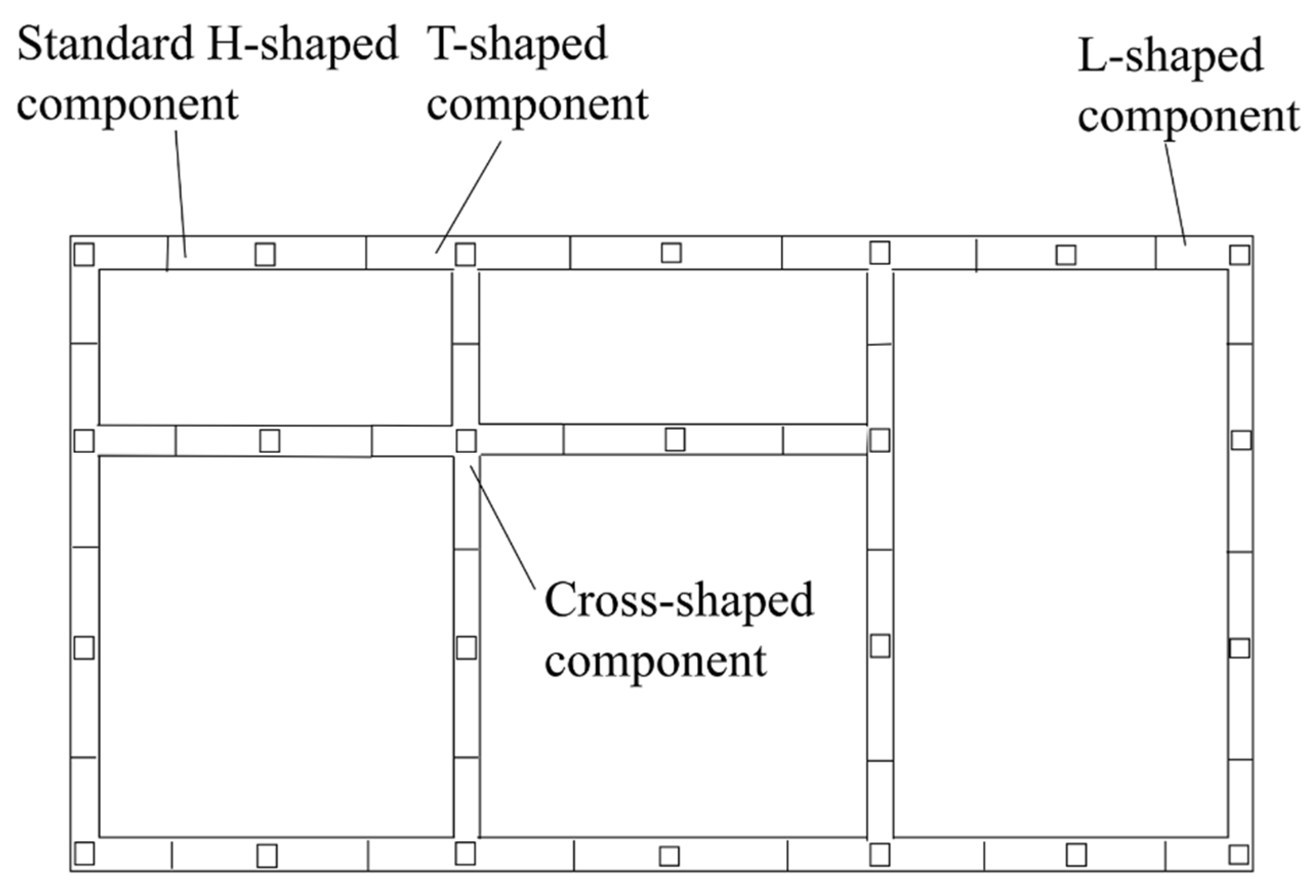
- The primary load-bearing components in this new form of prefabricated concrete structure are characterized by off-site prefabrication, which leads to excellent quality, high efficiency, and minimal pollution. Through the division and combination of four types of basic prefabricated cantilever components, it realizes the standardization of components while meeting the diverse demands of building types.
- (2)
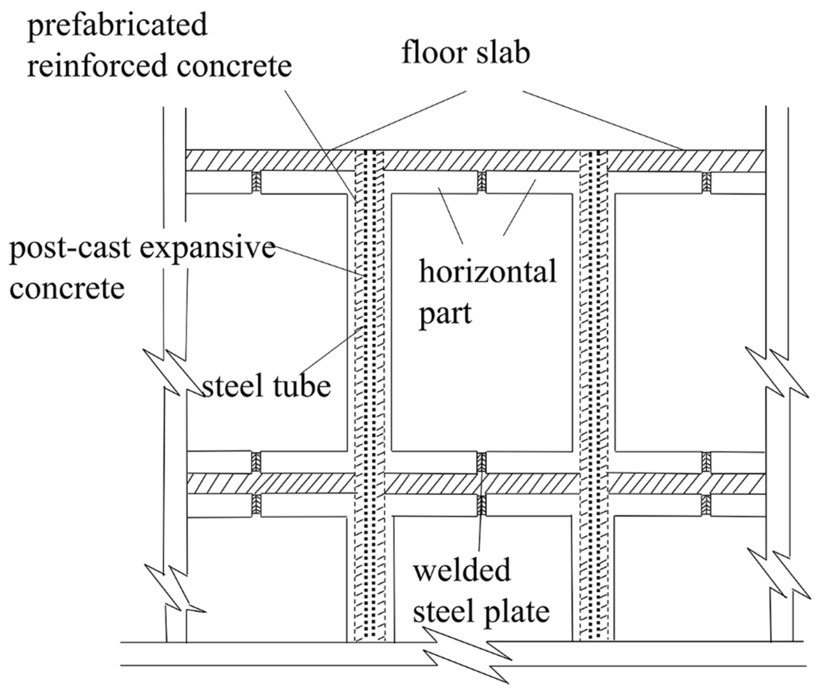
- The force transmission mechanism of an FTPC structure is clear, which provides convenience for design. The prefabricated cantilever components have a simple connection mode, which can facilitate construction. The workload of wet work is quite small, and the pouring of post-cast concrete does not require formwork. Each prefabricated component has a moderate volume, which leads to convenience for transportation and installation.
- (3)
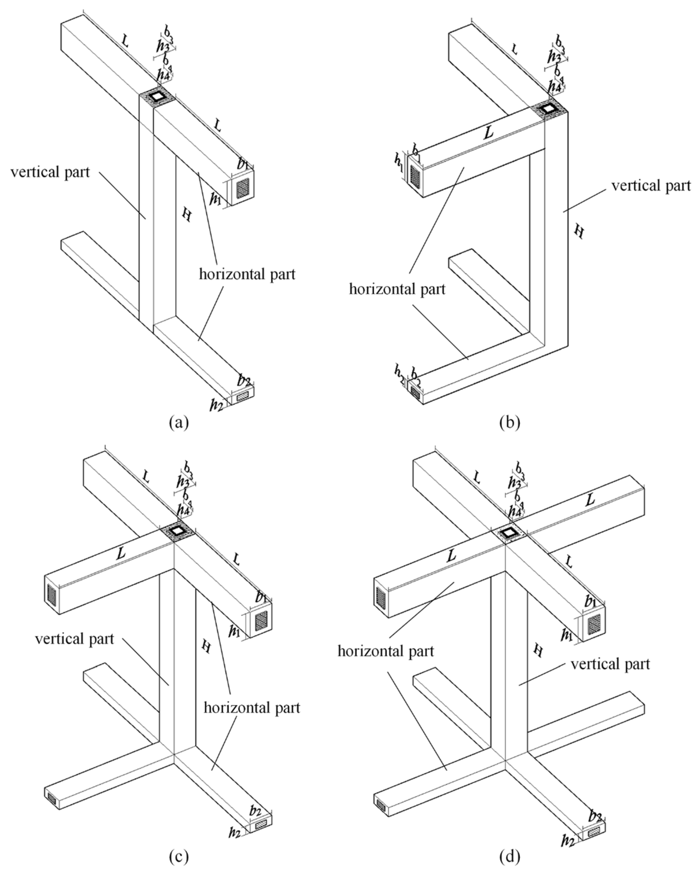
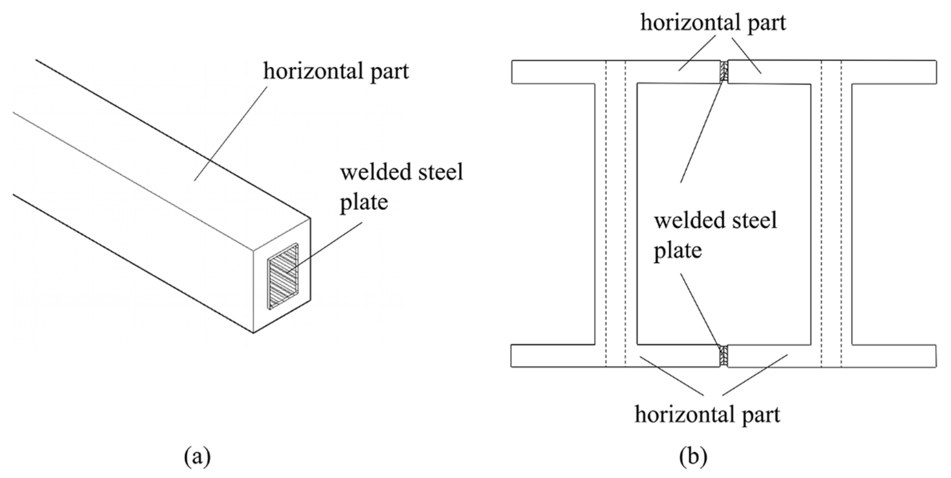
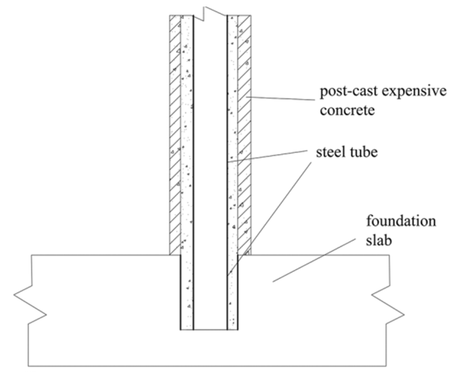
- Each prefabricated cantilever component is fixed by hollow steel tube and post-cast expansive concrete. Therefore, even if each prefabricated cantilever component is disconnected from an adjacent component on the same floor, which means that the welding of steel plates embedded at the outer end of the horizontal part is invalid, an FTPC structure will not become a mechanism, but rather is under a statically determinate state similar to a large tree with multiple layers of branches. The vertical part of the prefabricated cantilever component can be seen as the trunk, and the horizontal part can be seen as the branch. As a result, an FTPC structure has strong fault tolerance for on-site poor weld quality in the connection operation of the horizontal parts. Under normal circumstances, the welded joint can be regarded as a hinged joint because the tiny rotation under bending moment action is hard to avoid. If the poor weld quality makes the welded joint reach a disconnected state, an FTPC structure will not fail.
2.3. Key Design Points of an FTPC Structure
- (1)
- The location, type, and quantity of prefabricated cantilever components should be determined according to the specific situation of an actual engineering with the requirement that the number of component types should be minimized to achieve the maximum level of standardization.
- (2)
- In the initial stage of structural design, the type of floor slab and its force transmission mechanism should be determined first, and then the external size of each prefabricated cantilever component should be selected preliminarily. The type selection of reinforcement, concrete, and steel tube should then be carried out. The lightweight infill walls between the neighboring vertical parts of the prefabricated cantilever components are determined synchronously. The vertical load, wind load, and earthquake action can then be calculated according to GB 50009-2012 [].
- (3)
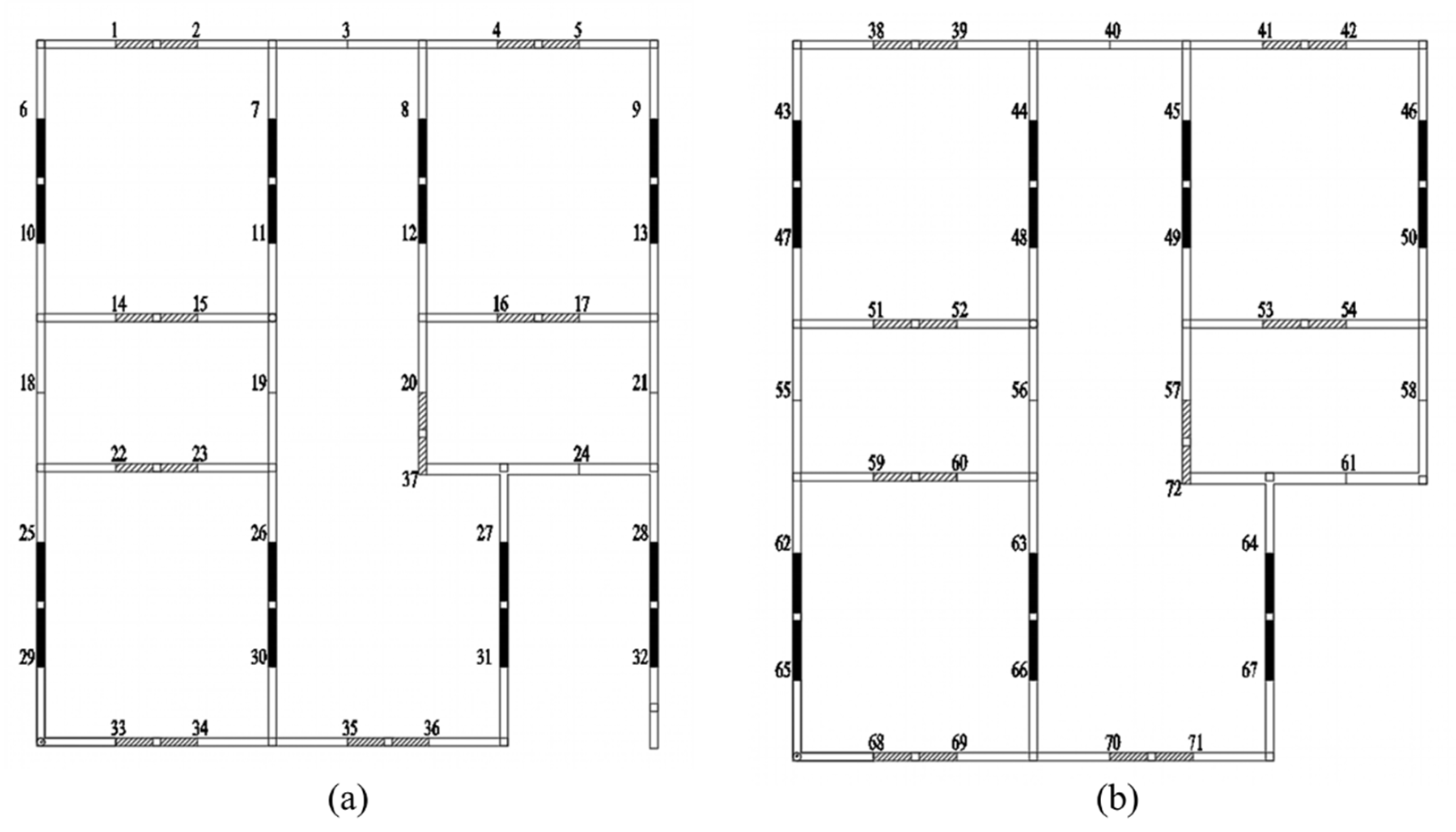
- Based on the fault-tolerant characteristics of an FTPC structure, methods of random mathematics can be used to select some connection nodes of horizontal parts of adjacent prefabricated cantilever components as disconnected nodes to consider the actual poor weld quality. According to different node selection schemes, several corresponding analytical models for an FTPC structure can be established to take into account the internal force condition of the structure under different weld quality statuses. The internal force analysis results of multiple models provide a basis for further component optimization design, which can improve the robustness of the overall structure and ensure structural safety better.
- (4)
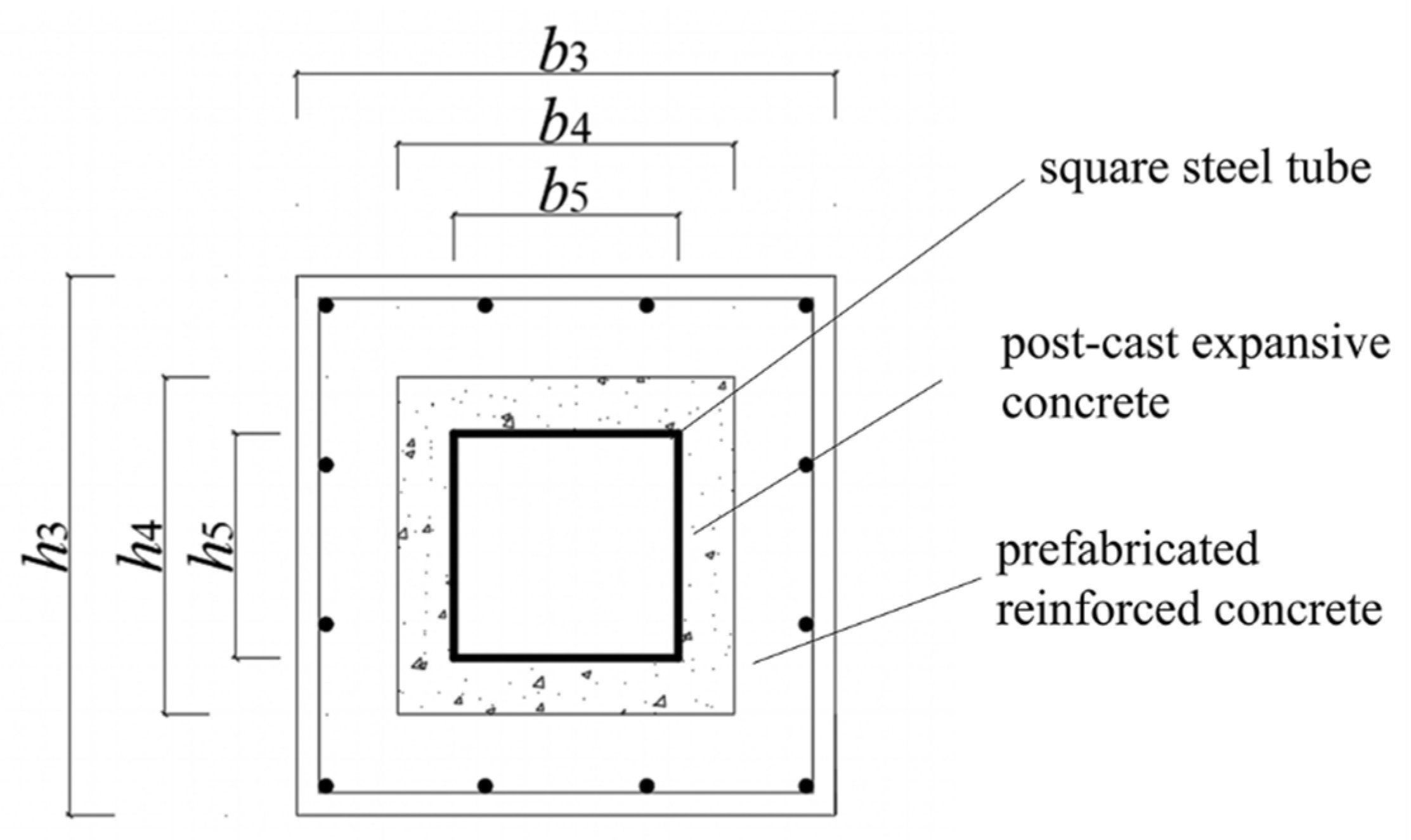
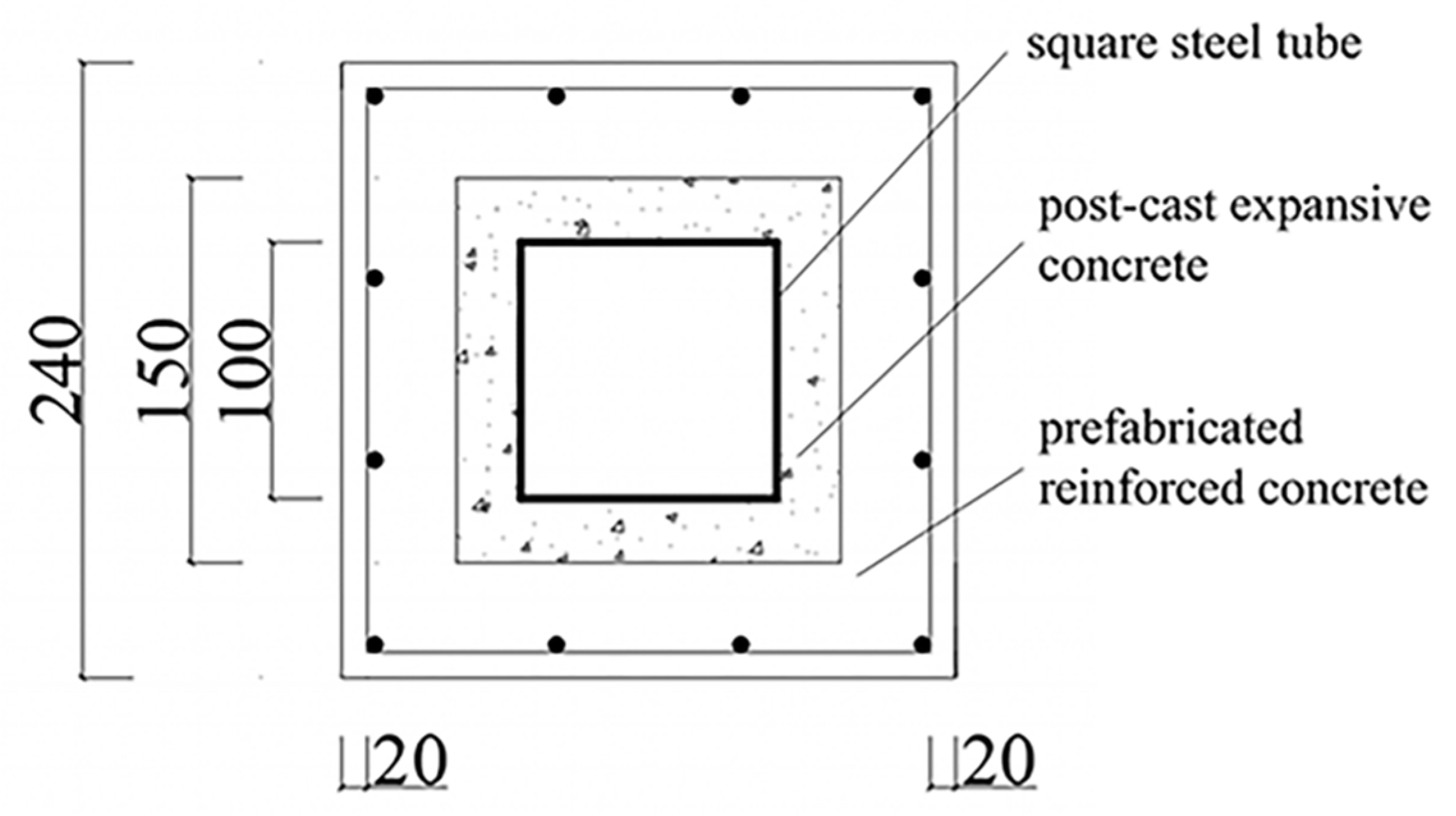
- The horizontal parts of the prefabricated cantilever components can be designed as ordinary reinforced concrete components, while the vertical parts should be designed as the steel–concrete composite components (section is shown as Figure 6).
3. Example Analysis
To verify the feasibility and rationality of an FTPC structure, a design example of a two-story villa building, whose architectural design scheme is shown in Figure 8, was proposed. This structure is 11.25 m in length, 12.84 m in width, 2.85 m in interstorey height, and 7.70 m in total height.
Figure 8.
Architectural design scheme of design example: (a) 3D schematic diagram of the building, (b) first floor, and (c) second floor.
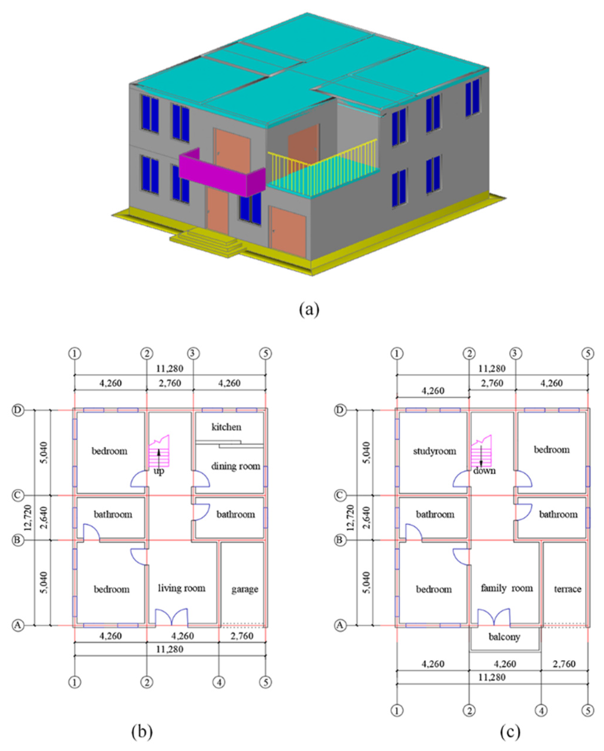
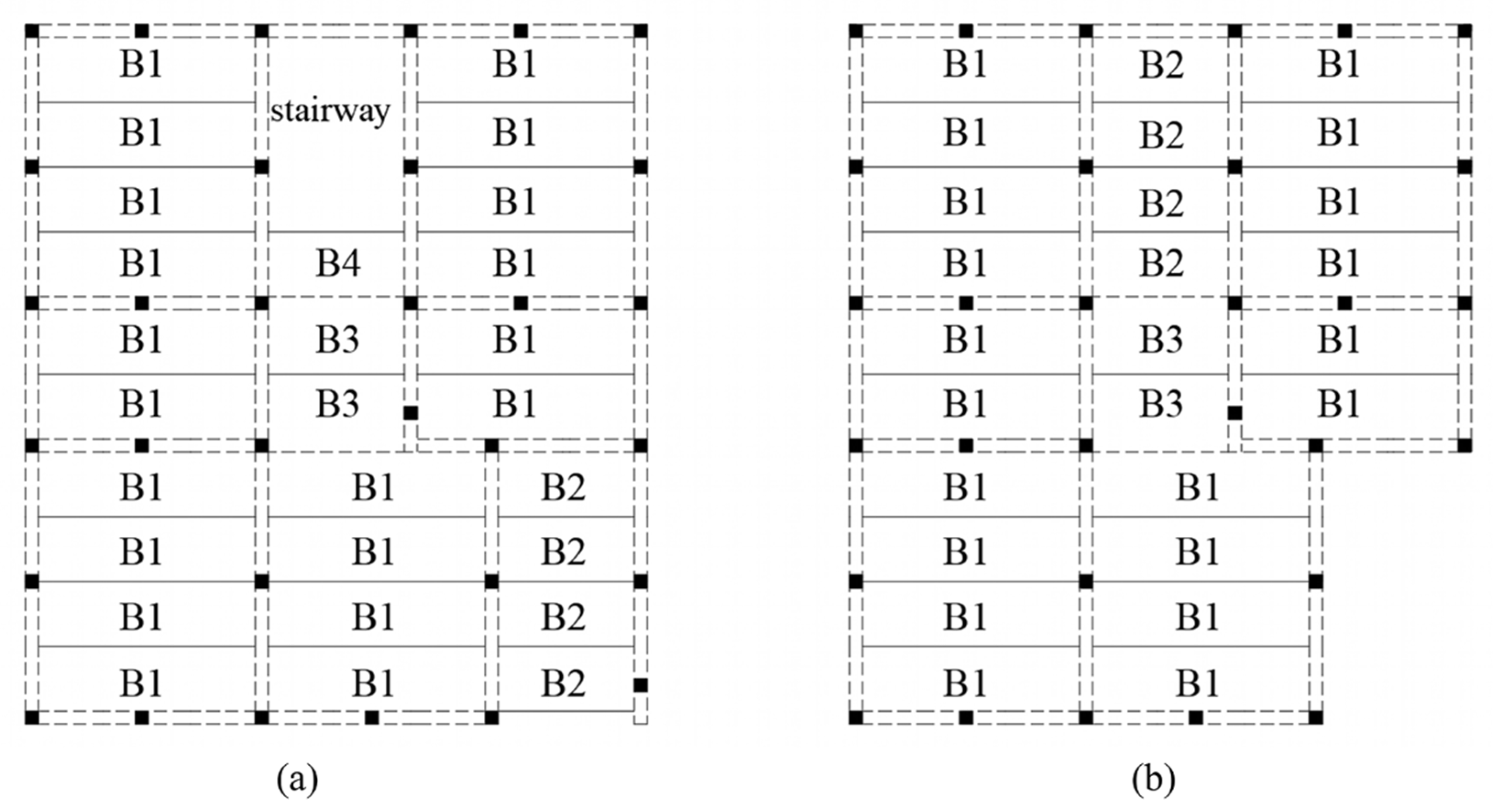
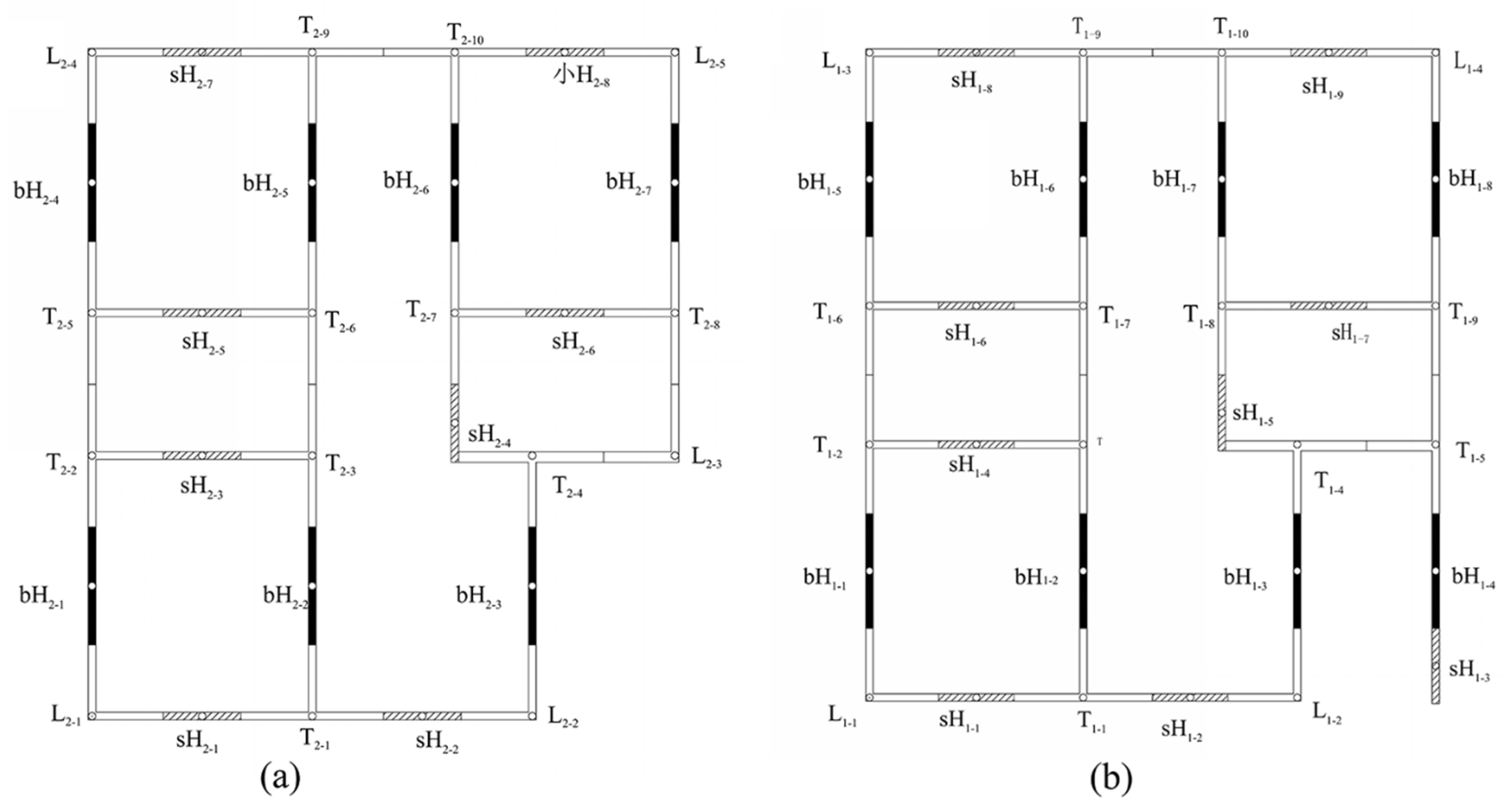
3.1. Type Selection and Design of Load-Bearing Components
For the horizontal load-bearing unit, one-way force transmission truss reinforced concrete composite slabs were employed. The flexural stiffness of the composite slab can be ensured by the high stiffness of steel truss, while the lower chord reinforcements of truss can be used as the load-bearing reinforcements at the bottom of the floor slab.
Corresponding to the architectural design scheme, four types of one-way force transmission truss reinforced concrete composite slabs (denoted by B1, B2, B3, and B4) were determined []. The dimensions and layout plan are shown in Table 1 and Figure 9.
Table 1.
Dimensions of composite slabs.
Figure 9.
Layouts of composite slabs: (a) first floor and (b) second floor.
For the vertical load-bearing unit, H-shaped components, L-shaped components, and T-shaped components were chosen and designed based on the architectural design scheme. It should be noted that two kinds of H-shaped components with different cantilever length L were designed: sH-shaped components and bH-shaped components (bH-shaped components have greater cantilever length than sH-shaped components). The dimensions, numbering, and layout of each prefabricated cantilever component are shown in Table 2 and Figure 10 and Figure 11.
Table 2.
Dimensions of prefabricated cantilever components.
Figure 10.
Positions and numbers of various types of prefabricated cantilever components: (a) first floor and (b) second floor.
Figure 11.
A 3D diagram of the prefabricated cantilever components arrangement: (a) First floor, (b) Second floor.
C30 concrete and HRB400 rebar was chosen for all types of prefabricated cantilever components, while C40 expansive concrete was used as the post-cast concrete in the vertical part.
Internal rebar in the vertical part of the prefabricated cantilever components were selected preliminarily as 12C12 (longitudinal rebar), C10@200 mm (stirrup). Thickness of protection cover is 20 mm. Square steel tubes with a thickness of 20 mm and external size of 100 mm × 100 mm were adopted as the hollow steel tube. The section schematic of the vertical part is shown in Figure 12.
Figure 12.
Section schematic of the vertical part of the prefabricated cantilever components (unit: mm).
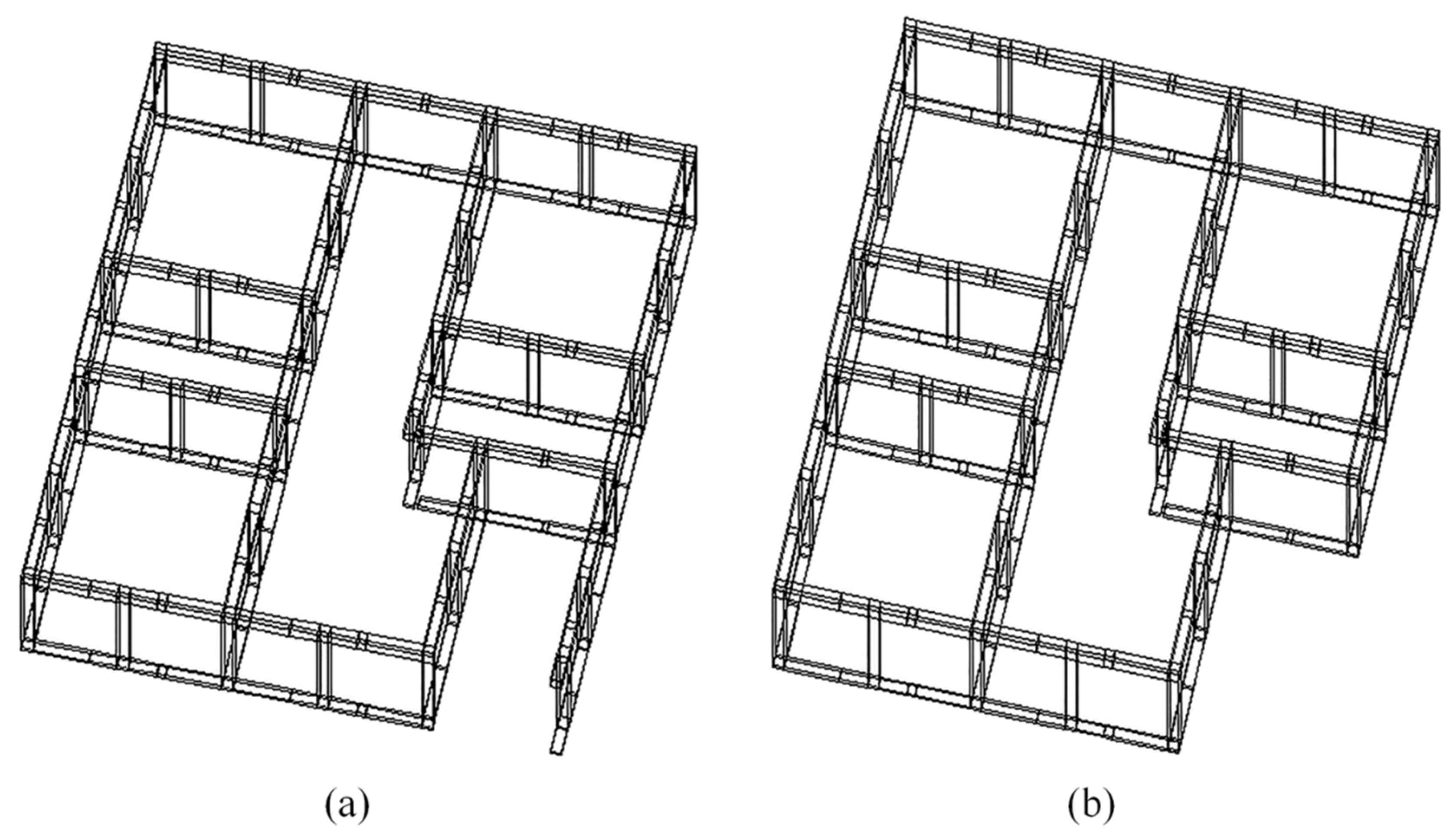
3.2. Analytical Model of the Overall Structure
SAP2000 was selected as the finite element software for the overall structure modeling. The frame element was adopted to simulate the prefabricated cantilever components.
For the horizontal part of the prefabricated cantilever components, elastic modulus (30,000 N/mm2) and Poisson’s ratio (0.3) were selected according to the concrete strength grade. For the vertical part, flexural stiffness [] was calculated by the superposition method in JGJ 138-2016 [], and then the equivalent elastic modulus (37,498.41 N/mm2) was obtained after conversion. The Poisson’s ratio was also taken as 0.3.
Each kind of vertical load and wind load was calculated (earthquake action was temporarily ignored in this example). The equivalent vertical uniform load of slabs was transferred to vertical load-bearing units according to the load transfer mechanism of the one-way slab. The overall structure model under the action of loads is shown in Figure 13.
Figure 13.
Schematic diagram of the overall structure model under the action of loads.
The vertical connection joints of each prefabricated cantilever component were set as rigid nodes. The vertical connection joints of prefabricated cantilever components on the first floor and foundation were set as rigid nodes, too. The horizontal connection joints (welded connection of steel plates) of each prefabricated cantilever component were numbered as shown in Figure 14.
Figure 14.
Number of horizontal connection joints of each prefabricated component: (a) joint number on the first floor and (b) joint number on the second floor.
Based on the fault-tolerant design concept, the joints occupying 0/4, 1/4, 2/4, 3/4, and 4/4 of total horizontal connection joints (welded joints) were considered to be disconnected (invalid connection), respectively. After the horizontal connection joints selected as invalid connection were set as disconnected nodes while the remaining joints were set as hinged nodes, the corresponding five different structural models (denoted as model 1, model 2, model 3-1, model 3-2, and model 3-3) could be established. In model 1, zero welded joints were set as disconnected nodes, which means that the connection quality of all welded joints is relatively ideal. In model 2, all the 72 welded joints were set as disconnected nodes, which means that the connection quality of all joints is very poor. In models 3-1, 3-2, and 3-3, 1/4, 2/4, and 3/4 of the total welded joints were considered to be disconnected nodes, respectively.
In models 3-1, 3-2, and 3-3, the selection of disconnected nodes could be performed by two random sampling methods: simple random sampling method [] or stratified sampling method []. Taking the model 3-2 (36 disconnected nodes) as the example, the sampling processes can be shown as below.
Simple random sampling method: A total of 36 nodes were randomly selected from 72 nodes one by one without replacement, which can ensure that the probability of each node being selected was the same. The sampling result is shown in Figure 15.
Figure 15.
Sampling result.
Stratified sampling method: The 72 nodes were divided into two groups according to the floor where the node is located. Some nodes (i.e., 18 nodes in the first floor and 18 nodes in the second floor) were randomly selected as disconnected nodes without replacement according to the proportion of nodes in that floor to the total nodes. It was guaranteed that every node in each floor had an equal probability of being selected. The sampling result is shown in Figure 15.
From the sampling results in Figure 15, there are 16 nodes selected on the first floor and 20 nodes selected on the second floor by simple random sampling. However, the total number of nodes on first floor is greater than that on the second floor (37 nodes on the first floor and 35 nodes on the second floor). Through simple random sampling, the selected nodes may be too concentrated on a certain floor, and the probability of every node being selected cannot be guaranteed to be the same or similar. It can be seen in Figure 15 that 18 nodes on the first floor and 18 nodes on the second floor were selected by the stratified sampling method. Generally, the stratified sampling method has the same characteristics as simple random sampling method in the sampling process and can further consider the influence of sample differences between strata on the sampling results after spatial stratification []. In this example, the stratified sampling method considers the difference in the number of nodes on the first and second floors. The nodes selected by the stratified sampling method are more scattered and the result is more representative. Therefore, the stratified sampling method was adopted in this example. The sampling results of models 3-1, 3-2, and 3-3 are shown in Table 3.
Table 3.
Sampling results of stratified sampling method.
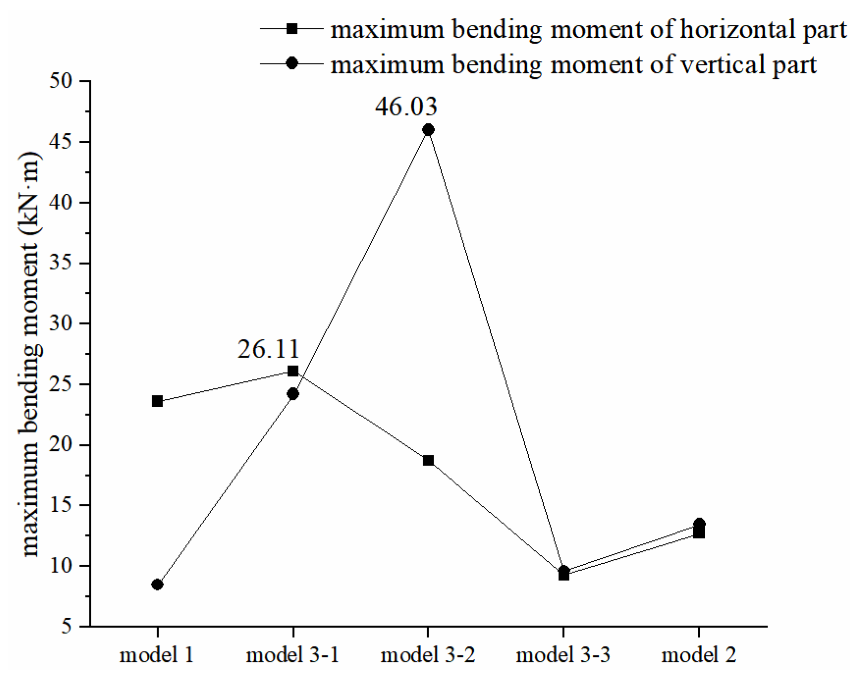
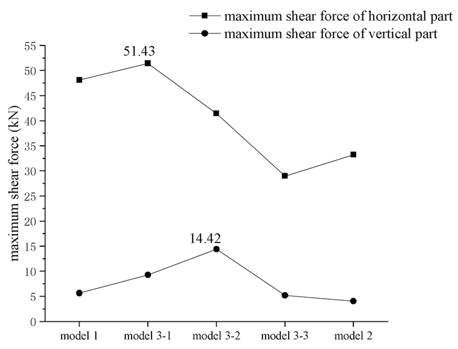
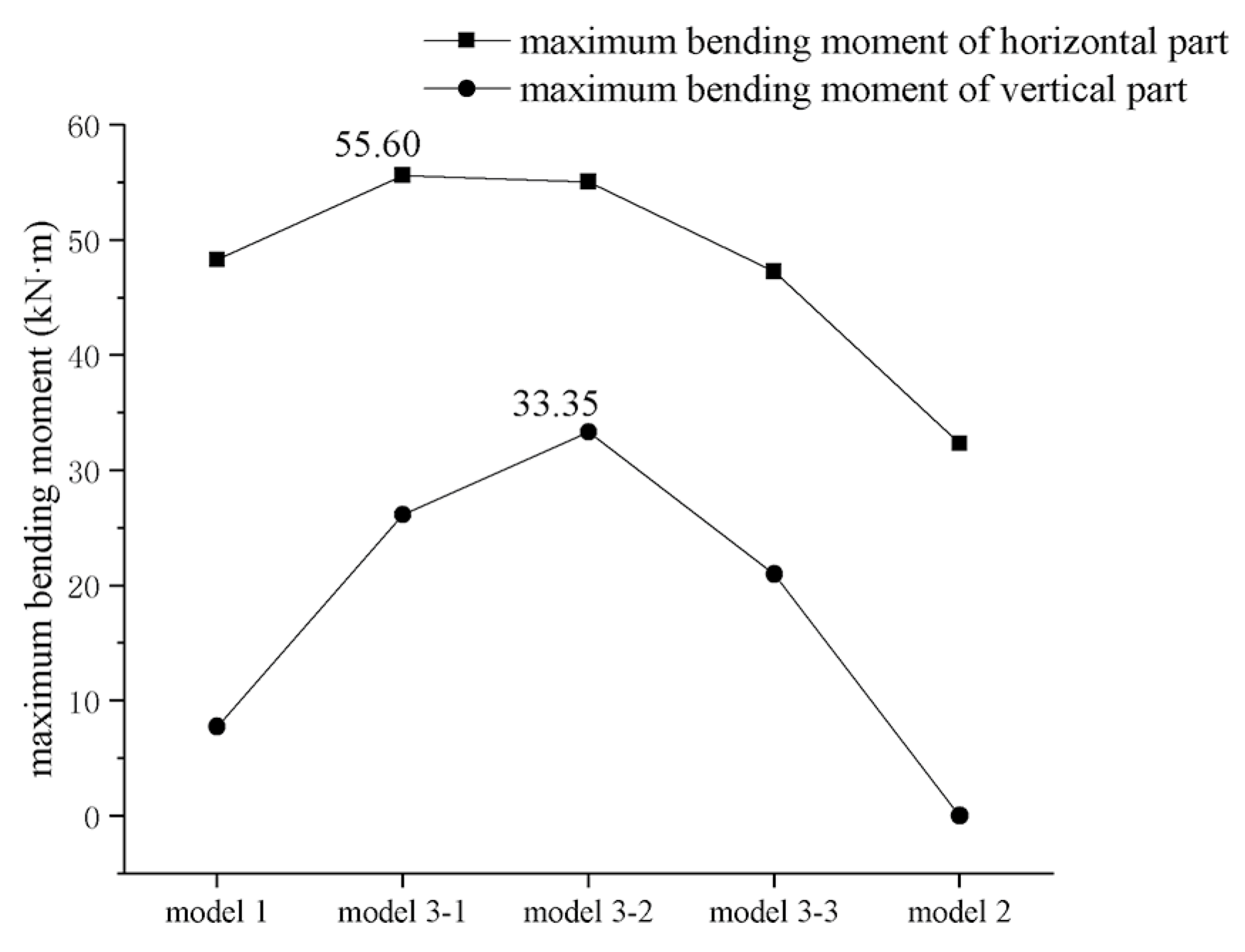
3.3. Internal Force Analysis and Comparison of Each Model
For the horizontal load-bearing unit on each floor (one-way truss reinforced concrete composite slab), internal force can be obtained according to the specific vertical load and boundary conditions. Corresponding special design can then be carried out, which will not be described in detail in this paper [].
The following focuses on the internal force analysis and comparison of the vertical load-bearing unit.
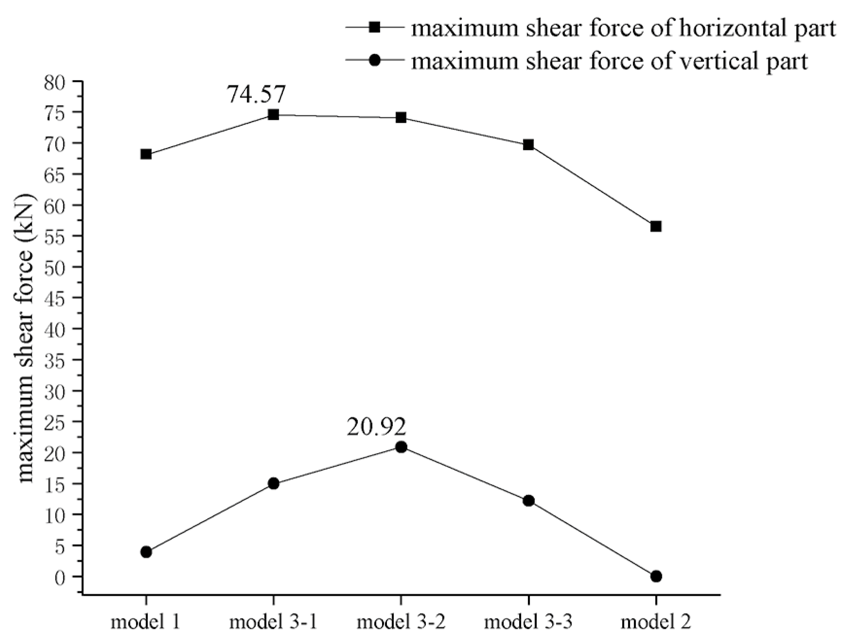
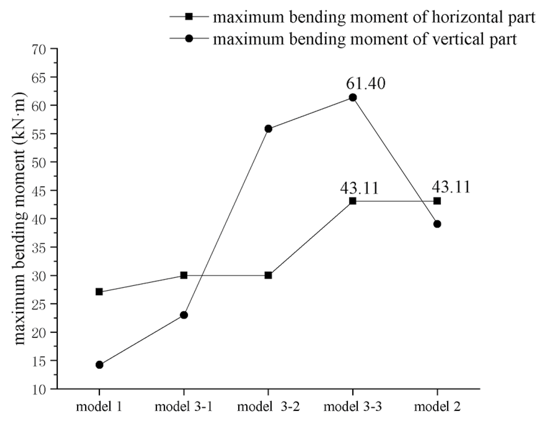
3.3.1. For the Whole Vertical Load-Bearing Unit
The upper horizontal parts of the prefabricated cantilever components on each floor form a “ring beam” type horizontal structure on the whole, which directly bears the loads transmitted from the floor slabs and nonload-bearing enclosure walls. In addition, the vertical part of each prefabricated cantilever component forms a “load-bearing column” on each floor. Internal force analysis and comparison was carried out for the horizontal part and vertical part below.
- (1)
- Upper horizontal part of each prefabricated cantilever component
For the 5 models:
Bending moment and shear force: The main types of internal forces, the prefabricated cantilever components containing the maximum bending moment and maximum shear force are located on the first floor of the structure. All the maximum bending moment and shear force values occur at the inner end section of the upper horizontal parts. The shear force of the outer end section is small, and the bending moment is 0, which can reduce the quality requirements for welded joints.
Axial force: As the components in model 2 are completely disconnected from other components, there is no axial load on the horizontal parts, leading to zero axial force in model 2; values in the other four models are small, and the corresponding maximum tensile and compressive stresses are far smaller than the concrete strength.
Torque: Due to loads of the balcony slab and stair slab, there are torques in the horizontal parts of the components connected to them. Only T1-1, sH1-2, L1-2, T1-7, and T1-8 components have torque, and the torque value at the same position in each model is the same.
The horizontal parts are mainly subjected to bending moment and shear force. Torque exists only in the horizontal parts of the components that support the balcony slab and stair slab. At the same time, small internal force appears on the inner end section of the horizontal part, leading to low requirements for the bearing capacity of welded joints.
- (2)
- Vertical part of each prefabricated cantilever component
For the 5 models:
Bending moment and shear force: Every vertical part has bending moment and shear force in model 1. In the other four models, some sH-shaped and bH-shaped components are completely disconnected, and the horizontal parts on both sides are subjected to the same bending moment and shear force, resulting in no bending moment and shear force in the vertical part; both bending moments and shear forces change linearly from the top section to the bottom section; components corresponding to the maximum bending moment are located on the second floor of the structure in model 1 while they are located on the first floor of the structure in the other models.
Axial force: The components on the first floor are the main load-bearing components, which need to bear the loads from the upper floor. The axial pressure increases linearly from the top section to the bottom section, and the components corresponding to the maximum value are located on the first floor of the structure.
Torque: Values are zero for the components that are completely disconnected from the adjacent components on the same floor (e.g., including all components in model 2, excluding all components in model 1); all other components have torque, and the torque value remains the same from the top section to the bottom section.
The internal forces of the vertical parts are complicated. Most of the vertical parts are under the combination of axial pressure, bending moment, shear force, and torque. With the increase of disconnected nodes, more and more components are disconnected from other components on the same floor. The internal force of each component in the same model varies greatly due to the different connection states. Some vertical parts only have axial force (e.g., bH1-3 completely disconnected from other components on the same floor in model 3-2), while others are under the combined action of axial pressure, bending moment, shear force, and torque (e.g., bH2-5 fully connected to components on the same floor in model 3-2).
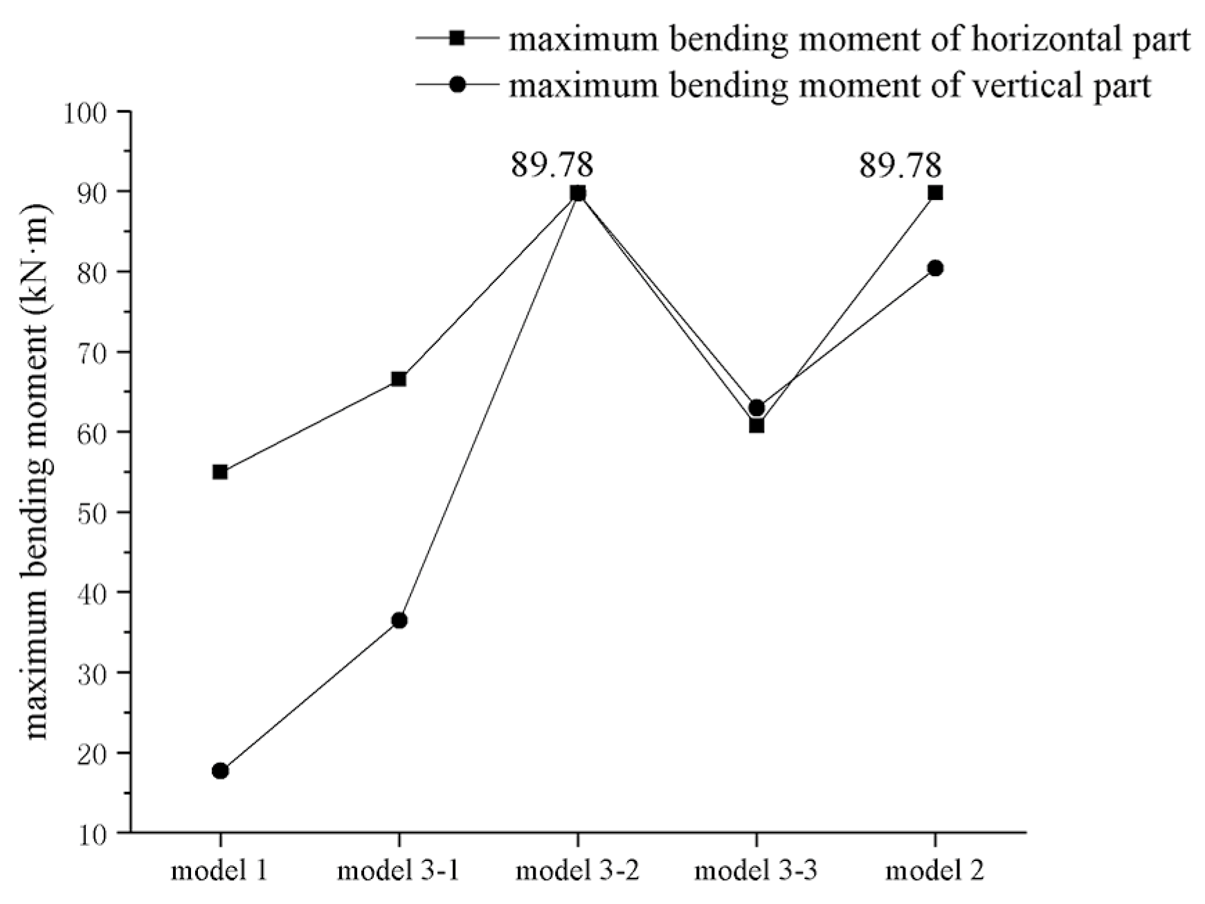
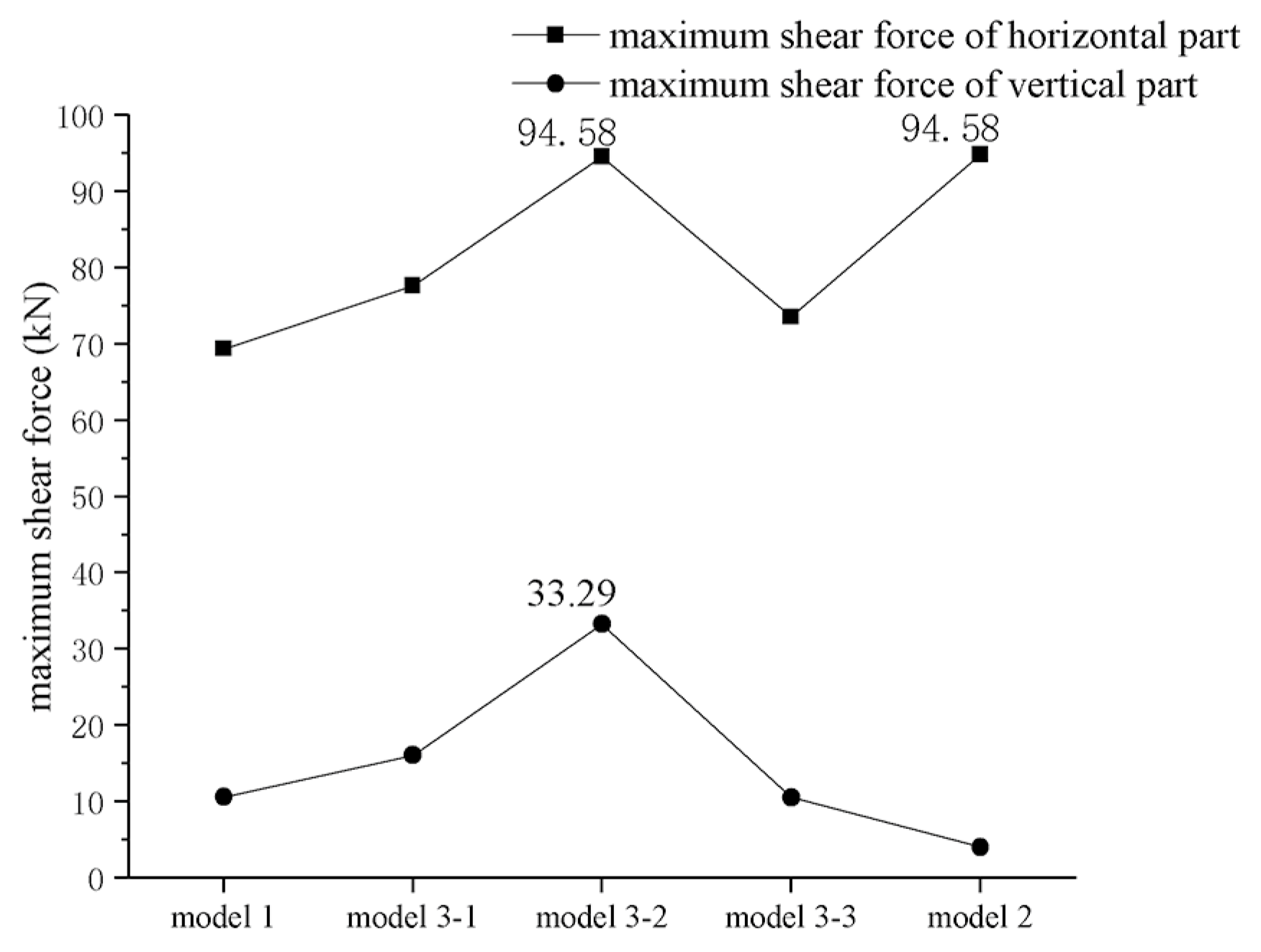
3.3.2. For Each Prefabricated Cantilever Component
The internal force condition of each type of prefabricated cantilever component were analyzed respectively. The results can be used as the design basis for each type of prefabricated cantilever component.
- (1)
- sH-shaped components
sH-shaped components can be divided into two types: components that only bear wind load (sH1-1, sH1-2, sH1-3, sH2-1, and sH2-2) and components that need to support the superimposed slab in the horizontal part (sH1-5, sH2-4, and sH1-2).
The sH1-5 component is different from other sH-shaped components because of the special position: the horizontal parts bear the load transmitted from the first floor and the load from the walls on the second floor. The component corresponding to the maximum bending moment and shear force of the horizontal part is sH1-5 in each model.
The components corresponding to the maximum bending moment and shear force of the vertical part are the components with wind load in each model. The component corresponding to the maximum axial force of the vertical part is the sH1-5 component in each model.
The component corresponding to the maximum shear force of the vertical part belongs to the second floor in model 2 while belonging to the first floor in the other models.
The maximum bending moment of the horizontal part reaches the relative maximum value in model 3-1, and the maximum bending moment of the vertical part reaches the relative maximum value in model 3-2, as shown in Figure 16. Affected by disconnected nodes, the maximum bending moment of the sH-shaped components occurs in the models where the components are partially disconnected.
Figure 16.
Maximum bending moments of the horizontal part and vertical part for the sH-shaped components in each model.
The maximum shear force of the horizontal part reaches the relative maximum value in model 3-1, and the maximum shear force of the vertical part reaches the relative maximum value in model 3-2, as shown in Figure 17. As can be seen from Figure 17, the shear force of the horizontal part is much larger than that of the vertical part in the same model. Meanwhile, affected by disconnected nodes, the maximum shear force of the sH-shaped components occurs in the models where the components are partially disconnected.
Figure 17.
Maximum shear forces of the horizontal part and vertical part for the sH-shaped components in each model.
Torque of the horizontal part: only the horizontal parts of sH1-2 have torque.
Torque of the vertical part: In model 1, the torque value of the vertical part of each component remains the same from top to bottom; in the remaining four models, there are sH-shaped components completely disconnected from the adjacent components on the same floor, and the torque of their vertical part is zero. For the remaining components, the torque values of the vertical part also remain the same from top to bottom.
- (2)
- bH-shaped components
All bH-shaped components are required to support the floor slabs but no wind loads.
As the horizontal parts of bH-shaped components on the first floor bear the load transmitted from the first floor and the load from the walls on the second floor, the internal forces of the horizontal part are large. The components with the maximum bending moment, maximum shear force, and maximum axial force of the horizontal part all appear on the first floor in each model.
In model 1, all the welded joints are well-connected, leading to the internal force of the vertical part being controlled by loads on themselves and the loads from other components. The components with the maximum value of bending moment and shear force are located on the second floor in model 1. In models 3-1, 3-2, and 3-3, the disconnected nodes reduce the influence of other components on the internal forces. The components with the maximum value of bending moment and shear force are located on the first floor. The bH-shaped components in model 2 are completely disconnected, resulting in zero bending moment and shear force.
The maximum bending moment of the horizontal part reaches the relative maximum value in model 3-1, and the maximum bending moment of the vertical part reaches the relative maximum value in model 3-2, as shown in Figure 18. From the numerical point of view, the maximum bending moment of the horizontal part is much larger than that of the vertical part in the same model. At the same time, affected by disconnected nodes, the maximum bending moment of bH-shaped components occurs in the models where the components are partially disconnected.
Figure 18.
Maximum bending moments of the horizontal part and vertical part for the bH-shaped components in each model.
The maximum shear force of the horizontal part reaches the relative maximum value in model 3-1, and the maximum shear force of the vertical part reaches the relative maximum value in model 3-2, as shown in Figure 19. As can be seen from Figure 19, the maximum shear force of the horizontal part is also much larger than that of the vertical part in the same model. In addition, affected by disconnected nodes, the maximum shear force of bH-shaped components occurs in the models where the components are partially disconnected.
Figure 19.
Maximum shear forces of the horizontal part and vertical part for the bH-shaped components in each model.
Torque of the horizontal part: since bH-shaped components do not support balcony or stair slabs, it is zero in all models.
Torque of the vertical part: In model 1, the torque value of the vertical part of each component remains the same from top to bottom; in the remaining four models, there are bH-shaped components completely disconnected from the adjacent components on the same floor, and the torque of their vertical part is zero. For the remaining components, the torque values of the vertical part also remain the same from top to bottom.
All the bH-shaped components need to support the floor. The internal forces of bH-shaped components are greatly affected by loads on themselves and the loads from other components. With the increase of disconnected nodes, the influence of other components gradually weakens. The internal forces of bH-shaped components in model 2 are only affected by the loads on themselves.
- (3)
- L-shaped components
For all L-shaped components, one side of the horizontal part needs to support the floor. Moreover, L1-1, L1-2, L2-1, L2-2, and L2-3 components directly bear wind load.
The components with the maximum bending moment and maximum shear force of the horizontal part are all located on the first floor of the structure in each model.
The components with the maximum shear force and maximum axial force of the vertical part are all located on the first floor of the structure in each model, too. At the same time, the vertical load on the horizontal part that supports the floor is much larger than that on the other horizontal part, resulting in the maximum bending moment and shear force being located on the horizontal part that supports floors.
The component with the maximum bending moment of the vertical part is located on the second floor of the structure in model 2 while it is located on the first floor of the structure in the other models.
The component with the maximum shear force of the vertical part is located on the second floor of the structure in model 1 while it is located on the first floor of the structure in the other models. In model 2, the components without wind load are completely disconnected from the other components on the same floor, resulting in no horizontal load on the components (the shear force of vertical parts is 0).
The maximum bending moment of the horizontal part is located at L1-2 in model 2 and model 3-1, which is disconnected from other components and bears large vertical loads. The maximum bending moment of the vertical part reaches the relative maximum value in model 3-3, as shown in Figure 20. Affected by disconnected nodes, the maximum bending moment of L-shaped components occurs in the models where the components are partially disconnected and totally disconnected.
Figure 20.
Maximum bending moments of the horizontal part and vertical part for the L-shaped components in each model.
The maximum shear force of the horizontal part reaches the relative maximum value in both model 3-3 and model 2. The maximum shear force of the vertical part reaches the relative maximum value in model 3-2, as shown in Figure 21. From the numerical point of view, the maximum shear force of the horizontal part is also much larger than that of the vertical part in the same model. Meanwhile, affected by disconnected nodes, the maximum shear force of L-shaped components occurs in the models where the components are partially disconnected or totally disconnected.
Figure 21.
Maximum shear forces of the horizontal part and vertical part for the L-shaped components in each model.
As L1-2 needs to support the balcony slab, torque exists only in the horizontal part of the L1-2 component, and the torque value at the same position is the same in each model.
Torque of the vertical part: In model 1, the torque value of the vertical part of each component remains the same from top to bottom; in the remaining four models, there are L-shaped components completely disconnected from the adjacent components on the same floor, and the torque of their vertical part is zero. For the remaining components, the torque values of the vertical part also remain the same from top to bottom.
- (4)
- T-shaped components
For all T-shaped components, one side or two sides of the horizontal part need to support the floor. Moreover, T1-1 and T2-1 components directly bear wind load.
T-shaped components on the first floor need to support the floor and the upper wall, resulting in large internal forces of the components on the first floor. The components with the maximum bending moment and maximum shear force of the horizontal part are all located on the first floor of the structure in each model. Moreover, the vertical load on the horizontal part that supports floor is much larger than that on the other horizontal part, resulting in the maximum bending moment and shear force being located on the horizontal part that supports floors.
The component with the maximum bending moment of the vertical part is located on the second floor of the structure in model 1 while it is located on the first floor of the structure in the other models.
The maximum bending moment of the horizontal part reaches the relative maximum value in both model 3-3 and model 2. The maximum bending moment of the vertical part reaches the relative maximum value in model 3-2, as shown in Figure 22. As can be seen from Figure 22, the maximum bending moment of model 1 is smaller than that of the other four models affected by disconnected nodes.
Figure 22.
Bending moments of the horizontal part and vertical part for the T-shaped components in each model.
The maximum shear force of the horizontal part reaches the relative maximum value in both model 3-2 and model 2. The maximum shear force of the vertical part reaches the relative maximum value in model 3-2, as shown in Figure 23. From the numerical point of view, the maximum shear force of the horizontal part is much larger than that of the vertical part in the same model. Meanwhile, affected by disconnected nodes, the maximum shear force of the L-shaped components occurs in the models where the components are partially disconnected or totally disconnected.
Figure 23.
Maximum shear forces of the horizontal part and vertical part for the T-shaped components in each model.
As the T1-1 component needs to support the balcony slab and T1-7 and T1-8 need to support the stair platform slab, there are bending moments acting on the axial direction of the horizontal part. Due to the bending moment of the balcony slab and the stair slab, there are torques in the horizontal parts of several components (T1-1, T1-7, and T1-8).
Torque of the vertical part: In model 1, the torque value of the vertical part of each component remains the same from top to bottom; in the remaining four models, there are T-shaped components completely disconnected from the adjacent components on the same floor, and the torque of their vertical part is zero. For the remaining components, the torque values of the vertical part also remain the same from top to bottom.
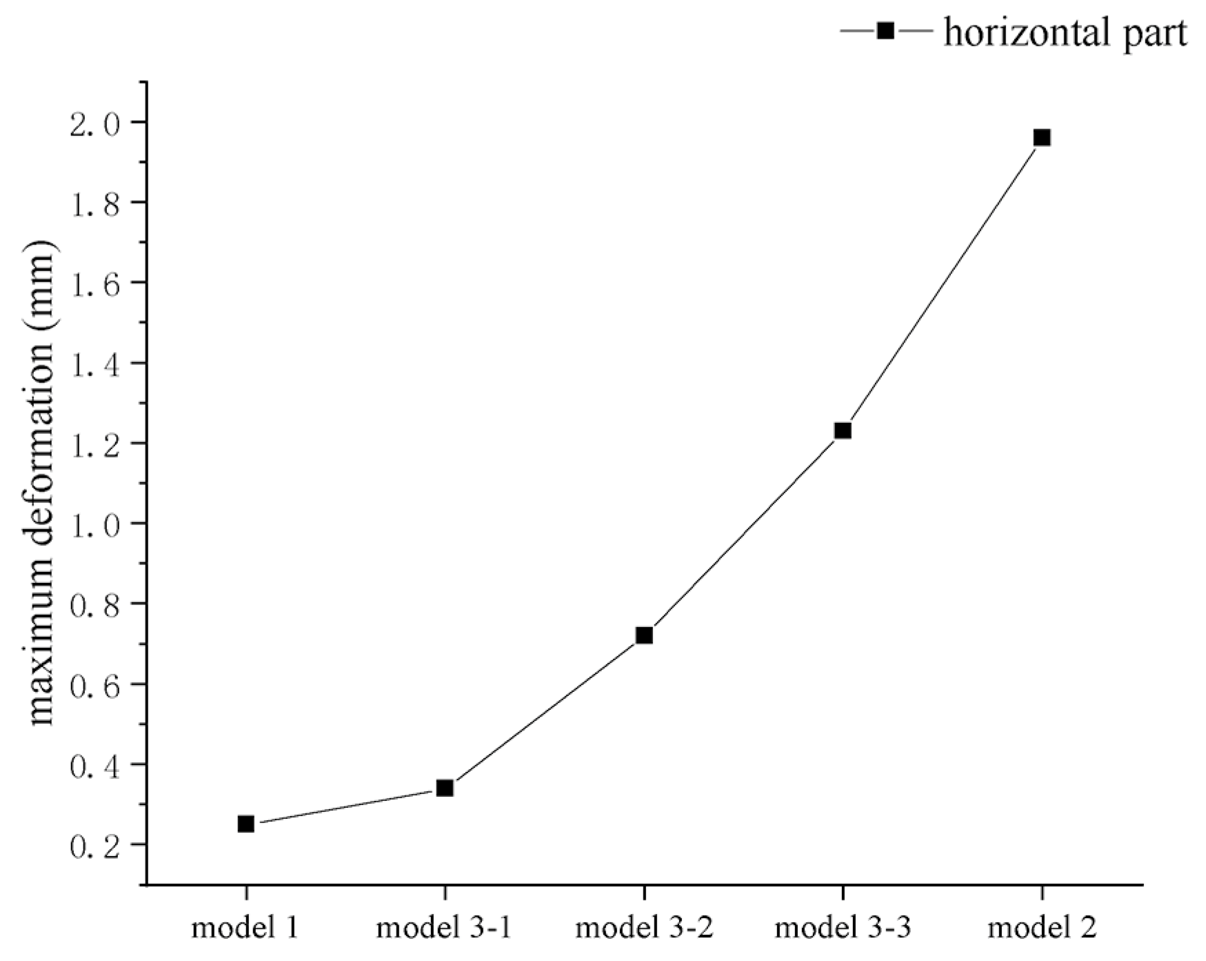
3.4. Analysis of Maximum Deformation of the Prefabricated Cantilever Components in Each Model
- (1)
- Maximum vertical displacement of the horizontal part
The displacement increases with the number of disconnected nodes in the model (in the order of model 1, model 3-1, model 3-2, model 3-3, and model 2), as shown in Figure 24.
Figure 24.
Maximum vertical displacements of the horizontal part of each model.
For the four types of prefabricated cantilever components, it is shown that the maximum vertical displacement values all meet the requirements of GB 50010-2010 [] that the displacement limit is l0/250 (l0 is taken as the cantilever length L of the horizontal part of each component, see Table 1 for details).
- (2)
- The maximum horizontal displacement of the vertical part (corresponding to the displacement angle between floors)
In each model, the maximum horizontal displacement occurs on the second floor of the structure, so that the maximum interfloor displacement angle of the overall structure also appears in the second floor. The maximum interfloor displacement angles all meet the requirements of JGJ 3-2010 [], as shown in Table 4.
Table 4.
Maximum interfloor displacement angle of each model.
3.5. Note
It can be seen from the above analysis that disconnected nodes have a certain influence on the internal force of the structure. The maximum value of each internal force is located in the model with disconnected nodes, but the deformations of the structure meet the requirements of the specification in every model. At the same time, the internal force of the welded connection section is small, which reduces the requirement for the bearing capacity of the welding quality.
In the follow-up, enveloping design can be carried out based on the internal force status of various types of prefabricated cantilever components shown in Section 3.3.2. The final design results of the horizontal and vertical parts of each type of component can be determined:
The horizontal part can be designed according to the design method of ordinary reinforced concrete components: As torque exists in some components, sH-shaped components should be designed by the combination of bending moment, torque, and shear force; bH-shaped components can be designed according to the combination of bending and shearing; the L-shaped and T-shaped components have horizontal parts in different directions and should be designed according to the horizontal parts supporting the floor to achieve standardization.
The vertical part needs to be designed according to a special type of steel reinforced concrete member with the section including concrete of the precast member, post-cast expansive concrete, shaped steel, and rebars. The specific method needs further research.
4. Conclusions
A new kind of prefabricated reinforced concrete technology based on fault-tolerant design, the FTPC (fault-tolerant prefabricated concrete) structure, was proposed and comprehensively introduced in terms of basic compositions, connection mode, and key points of design in this paper. The structural characteristics and the connection mode of four types of prefabricated cantilever components that are designed innovatively and manufactured in factory as key load-bearing components were mainly introduced in detail. The feasibility of FTPC structure was verified by a two-story structure analysis example. The following are the main conclusions.
- (1)
- Four types of prefabricated cantilever components serve as the vertical load-bearing unit of an FTPC structure. Through the different combinations of these four standard components, a variety of house types can be fully satisfied, leading to great promotion and application value.
- (2)
- The vertical connection method is more convenient than traditional wet methods while achieving an equivalent cast-in-place connection. Moreover, the characteristic of small force in the welded section reduces the quality requirement for welding.
- (3)
- The multimodel method based on the mathematical method considering the failure nodes is feasible. The fault-tolerant design can be realized by the multimodel analysis of the overall structure and the envelope design of the load-bearing parts. With five model structures, it has been verified that the safety of an FTPC structure meets the requirements.
- (4)
- The moderate volume of the prefabricated components leads to convenience for transportation and installation.
- (5)
- The vertical part of the cantilevered component under the combined loads needs further study about bearing capacity. The quantitative method of weld quality and its influence on the overall robustness of an FTPC structure can be considered more delicately in the future.
In summary, an FTPC structure is a well-designed structure. Four types of cantilevered components can be easily combined to meet the need of diverse house types. At the same time, efficient connection methods and the moderate size of components bring convenience to the construction. Small force in the welded section reduces the quality requirement for welding. A reasonable welded joints failure consideration method and multimodel analysis methods provide the analytical basis for fault-tolerant component design. Research on the bearing capacity of the vertical part and the quantification of welded joints will be the focus of future work.
Author Contributions
Conceptualization, Y.W. (Yilin Wang) and S.W.; methodology, Y.W. (Yilin Wang) and S.W.; software, Y.W. (Yilin Wang); validation, Y.W. (Yilin Wang), S.W. and D.S.; formal analysis, Y.W. (Yilin Wang) and S.W.; investigation, S.W.; resources, Y.W. (Yilin Wang); data curation, D.S. and Y.W. (Yu Wang); writing—original draft preparation, S.W.; writing—review and editing, Y.W. (Yilin Wang); visualization, S.W.; supervision, S.W.; project administration, Y.W. (Yilin Wang); funding acquisition, Y.W. (Yilin Wang) All authors have read and agreed to the published version of the manuscript.
Funding
This work was funded by the National Natural Science Foundation of China, grant number 51608311 and Program for Changjiang Scholars and Innovative Research Team in the University of China, grant number IRT13075.
Institutional Review Board Statement
Not applicable.
Informed Consent Statement
Not applicable.
Data Availability Statement
Not applicable.
Acknowledgments
The authors wish to express their appreciation and gratitude to the anonymous reviewers for their insightful comments and suggestions to improve the paper’s quality.
Conflicts of Interest
The authors declare no conflict of interest.
References
- Tavares, V.; Gregory, J.; Kirchain, R.; Freire, F. What is the potential for prefabricated buildings to decrease costs and contribute to meeting EU environmental targets? Build. Environ. 2021, 206, 108382. [Google Scholar] [CrossRef]
- Yrjl, J.; Bujnak, J. Shear tests on demountable precast column connections. Struct. Concr. 2021, 22, 2432–2442. [Google Scholar] [CrossRef]
- Ye, M.; Jiang, J.; Chen, H.M.; Zhou, H.Y.; Song, D.D. Seismic behavior of an innovative hybrid beam-column connection for precast concrete structures. Eng. Struct. 2021, 227, 111436. [Google Scholar] [CrossRef]
- Tong, C.; Wu, J.; Li, C.Y. A novel precast concrete beam-to-column connection with replaceable energy-dissipation connector: Experimental investigation and theoretical analysis. Bull. Earthq. Eng. 2021, 12, 4911–4943. [Google Scholar] [CrossRef]
- Huang, W.; Jiang, J.; Hu, G.X.; Zhang, J.R. Experimental study on the seismic performance of new precast concrete beam-column joints with replaceable connection. Structures 2022, 35, 856–872. [Google Scholar] [CrossRef]
- Chen, Y.; Shi, H.R.; Wang, C.L.; Wu, J.; Liao, Z.Q. Flexural mechanism and design method of novel precast concrete slabs with crossed bent-up rebar. Bull. Earthq. Eng. 2022, 50, 104216. [Google Scholar] [CrossRef]
- Wang, M.F.; Guo, S.Q.; Jing, F.; Zhang, Y.Q. Seismic performance of superimposed RC shear walls with concealed bracings using different horizontal connections. J. Build. Eng. 2022, 51, 104258. [Google Scholar] [CrossRef]
- Bei, C.; Yuan, C.; Looi, D.T.W. Experiment and numerical study of a new bolted steel plate horizontal joints for precast concrete shear wall structures. Structures 2021, 32, 760–777. [Google Scholar] [CrossRef]
- Naserpour, A.; Fathi, M. Numerical study of a multiple post-tensioned rocking wall-frame system for seismic resilient precast concrete buildings. Earthq. Eng. Eng. Vib. 2022, 21, 377–393. [Google Scholar] [CrossRef]
- Kurama, Y.C.; Sritharan, S.; Fleischman, R.B.; Restrepo, J.I.; Henry, R.S.; Cleland, N.M.; Ghosh, S.K.; Bonelli, P. Seismic-Resistant Precast Concrete Structures: State of the Art. J. Struct. Eng. 2018, 144, 03118001. [Google Scholar] [CrossRef] [Green Version]
- Lu, Y.J.; Wu, D.Y.; Peng, X.D.; Wang, S.L.; Wang, X.; Chen, W.; Wang, S.L. Study on the low cyclic loading test of a new reinforced tenon precast shear wall under different axial compression ratios. Adv. Struct. Eng. 2022, 4, 1631–1641. [Google Scholar] [CrossRef]
- Su, H.; Chen, W.; Wu, D.Y.; Wu, Q.; Wang, S.L.; Wang, W. Experimental study on seismic performance of new reinforced tenon joint precast shear walls. Adv. Struct. Eng. 2021, 24, 1631–1641. [Google Scholar] [CrossRef]
- Yang, Y.; Ding, X.; Liu, Y.; Deng, L.; Lv, F.; Zhao, S. Lateral Pressure Test of Vertical Joint Concrete and Formwork Optimization Design for Monolithic Precast Concrete Structure. Buildings 2022, 12, 261. [Google Scholar] [CrossRef]
- Li, J.B.; Fan, Q.Q.; Lu, Z.; Wang, Y. Experimental study on seismic performance of T-shaped partly precast reinforced concrete shear wall with grouting sleeves. Struct. Des. Tall Spec. Build. 2019, 28, e1632.1–e1632.13. [Google Scholar] [CrossRef]
- Fang, Z.; Fang, S.; Liu, F. Experimental and Numerical Study on the Shear Performance of Short Stud Shear Connectors in Steel–UHPC Composite Beams. Buildings 2022, 12, 418. [Google Scholar] [CrossRef]
- Ng, W.H.; Kong, S.Y.; Chua, Y.S.; Bai, Y. Tensile behaviour of innovative one-sided bolts in concrete-filled steel tubular connections. J. Constr. Steel Res. 2022, 191, 107165. [Google Scholar] [CrossRef]
- Guo, H.S.; Shi, P.F.; Qi, H.; Wu, B.; Pan, P.; Li, L.M.; Li, L.M.; Liu, K.; Wang, D.Y. Full-scale experimental study on post-tensioned prestressed precast frame structures. J. Build. Struct. 2021, 42, 119–132. (In Chinese) [Google Scholar] [CrossRef]
- Zhu, H.; He, Y.; Ji, D.; Tang, J.; Li, C. Experimental Research on the Mechanical Properties and Autogenous Shrinkage of Precast Members Joint Concrete. Buildings 2022, 12, 373. [Google Scholar] [CrossRef]
- Abusafaqa, F.R.; Samaaneh, M.A.; Dwaikat, M.B.M. Improving ductility behavior of sway-special exterior beam-column joint using ultra-high performance fiber-reinforced concrete. Structures 2022, 36, 979–996. [Google Scholar] [CrossRef]
- Liu, Y.L.; Zhu, S.T. Finite element analysis on the seismic behavior of side joint of Prefabricated Cage System in prefabricated concrete frame. Front. Struct. Civ. Eng. 2019, 13, 1095–1104. [Google Scholar] [CrossRef]
- Wang, X.; Li, L.Z.; Deng, B.Y.; Zhang, Z.; Jia, L. Experimental study on seismic behavior of prefabricated RC frame joints with T-shaped columns. Eng. Struct. 2021, 233, 111912. [Google Scholar] [CrossRef]
- Li, Y.; Zhang, L.; Zhang, Q.; He, X.; Su, Y. Anchorage behavior of grouting sleeves under uniaxial and cyclic loading-A comparative study of the internal structure of sleeves. J. Build. Eng. 2022, 49, 104057. [Google Scholar] [CrossRef]
- Liu, Y.; Zhao, Z.; Cheng, X.; Li, Y.; Diao, M.; Sun, H. Experimental and numerical investigation of the progressive collapse of precast reinforced concrete frame substructures with wet connections. Eng. Struct. 2022, 256, 114010. [Google Scholar] [CrossRef]
- Guo, T.; Yang, J.; Wang, W.; Li, C. Experimental investigation on connection performance of fully-grouted sleeve connectors with various grouting defects. Constr. Build. Mater. 2022, 327, 126981. [Google Scholar] [CrossRef]
- Xu, L.H.; Wang, Q.L.; Yu, M.; Chi, Y.; Yang, B.; Liu, M.; Ye, J.Q. Experimental Study on Seismic Behavior of Cluster-Reinforced Precast Concrete Columns with Grouting-Anchor Connections. J. Earthq. Tsunami 2019, 13, 70–89. [Google Scholar] [CrossRef] [Green Version]
- Sayadi, A.A.; Rahman, A.B.A.; Jumaat, M.Z.B.; Alengaram, U.J.; Ahmad, S. The relationship between interlocking mechanism and bond strength in elastic and inelastic segment of splice sleeve. Constr. Build. Mater. 2014, 55, 227–237. [Google Scholar] [CrossRef]
- Ministry of Housing and Urban-Rural Development (MOHURD). GB 50009-2012 Load Code for the Design of Building Structures; China Architecture & Building Press: Beijing, China, 2012. (In Chinese)
- Wang, Y.L.; Zhao, H.K.; Liu, Q.L.; Li, G.N. Floor design method and example based on concrete composite slab reinforced by one-way truss bars. Eng. Constr. 2020, 52, 23–29. (In Chinese) [Google Scholar] [CrossRef]
- Wang, Y.L.; Zhao, H.K.; Liu, Q.L.; Li, G.N. Classification research on the section flexural stiffness setermination method of steel reinforced concrete columns. J. Chongqing Univ. Sci. Technol. (Nat. Sci. Ed.) 2020, 22, 97–101. (In Chinese) [Google Scholar] [CrossRef]
- Ministry of Housing and Urban-Rural Development (MOHURD). JGJ 138-2016 Code for Design of Composites; China Architecture & Building Press: Beijing, China, 2016. (In Chinese)
- Qiu, G.X.; Eftekharian, A. Extropy information of maximum and minimum ranked set sampling with unequal samples. Commun. Stat.-Theory Methods 2021, 50, 2979–2995. [Google Scholar] [CrossRef]
- Takumi, S. Mann–Whitney test for two-phase stratified sampling. Stat 2021, 10, e321.1–e321.9. [Google Scholar] [CrossRef]
- Igwe, N.O.; Bassey, U.; Oyah, M.P. Comparative analysis of the efficiency of simple random sampling and stratified random sampling techniques using data from 2006 population Fig.s of the six south-south states of nigeria. Int. J. Adv. Res. (IJAR) 2020, 8, 1056–1064. [Google Scholar] [CrossRef] [Green Version]
- Ministry of Housing and Urban-Rural Development (MOHURD). GB 50010-2010 Code for Design of Concrete Structures; China Architecture & Building Press: Beijing, China, 2010. (In Chinese)
- Ministry of Housing and Urban-Rural Development (MOHURD). JGJ 3-2010 Technical Specification for Concrete Structures of Tall Building; China Architecture & Building Press: Beijing, China, 2010. (In Chinese)
Publisher’s Note: MDPI stays neutral with regard to jurisdictional claims in published maps and institutional affiliations. |
© 2022 by the authors. Licensee MDPI, Basel, Switzerland. This article is an open access article distributed under the terms and conditions of the Creative Commons Attribution (CC BY) license (https://creativecommons.org/licenses/by/4.0/).