Article

Full-Scale Prefabrication and Non-Destructive Quality Monitoring of Novel Bridge Substructure for “Pile-Column Integration”

1
Bridge Engineering Research Institute, Guangxi Transportation Science and Technology Group Co., Ltd., Nanning 530007, China
2
School of Civil Engineering, Southeast University, Nanjing 211189, China
3
Guangxi Beibu Gulf Investment Group Co., Ltd., Nanning 530029, China
4
College of Transportation, Jilin University, Changchun 130025, China
*
Author to whom correspondence should be addressed.
These authors contributed equally to this work.
Buildings 2022, 12(6), 715; https://doi.org/10.3390/buildings12060715
Submission received: 19 April 2022 / Revised: 20 May 2022 / Accepted: 21 May 2022 / Published: 25 May 2022
(This article belongs to the Special Issue Sustainable Building Infrastructure and Resilience)

Abstract

:
The assembly process of “pile-column integration” is proposed in this study and applied in the engineering with the characteristics that most of the pile foundations are end-bearing piles, which is conducive to returning to the normal operation of transportation infrastructure in a timely manner. From the perspective of practical application, the bridge structure components, including pile column and cap beam, are reasonably designed and prefabricated according to the requirements of the reconstruction and expansion project of the old bridge. Through non-destructive testing technologies, the concrete strength, cover thickness of reinforcement, and component size of prefabricated components are monitored and tested to evaluate the quality of full-scale prefabricated bridge substructure for “pile-column integration”. The monitoring results showed that the concrete strength monitoring results of prefabricated components by the rebound method are relatively stable. The concrete strength of the prefabricated components was higher than the design concrete strength and their qualified rate was 100%. According to the monitoring of cover thickness of reinforcement, the measured cover thickness of reinforcement in prefabricated components by electromagnetic induction method fell within the allowable range, and their qualified rates were around 90%. The concrete strength and cover thickness of reinforcement for prefabricated components could meet the design requirements. Although the component size of the prefabricated components could be tested by a 3-D point cloud scanning system, the monitoring effect of a relatively smaller component size still needs to be improved. The quality monitoring of full-scale bridge substructures for “pile-column integration” proved the rationality of prefabrication and the feasibility of non-destructive testing technologies, providing references for the application of “pile-column integration”.

1. Introduction

As important transportation facilities, roads and bridges provide great convenience for people’s life and production [1,2,3,4]. The development model of a resource-saving and environment-friendly society puts forward more urgent requirements for the development of transportation and the construction of roads and bridges [5,6,7]. The proposal of a prefabricated bridge structure is the way for building industrialization, which can realize the construction process of low energy consumption and low emission, and effectively realize the green development requirements of the construction industry [8,9,10]. Meanwhile, the prefabricated bridge structure would also accelerate urbanization and the rapid development of highway construction, which is conducive to returning to the normal operation of transportation infrastructure in a timely manner.
The cast-in-situ concrete construction method is still the most commonly used in the field of bridge construction [11,12]. This construction method has a long construction period and many wet operations on-site, which will have a great impact on the surrounding environment. In addition, the consumption of supports and formwork in the construction is large, leading to a high construction cost, and it directly affects the load capacity of the construction site, which is inconsistent with the development requirements of urban and rural construction [13,14]. Especially when the highway passes through mountainous areas or environmentally sensitive areas, under the construction conditions of ecological and environmental protection, it is urgent to find bridge construction methods which can reduce the environmental impact and develop China’s prefabricated bridge structure.
To deal with the defects of cast-in-situ concrete construction, prefabricated bridges have been widely used abroad [9,15,16,17]. In 1971, the first bridge with segmental pier technology, i.e., the Corpus Christi Causeway Bridge, was completed in Texas, USA [18,19]. In 1987, the pier structure of Linn Cove Viaduct used prefabrication and assembly technology to reduce the impact on the surrounding environment during the construction process, speed up the project construction progress, and complete the project construction ahead of schedule, which has become a classic engineering example in the prefabrication and assembly bridge structure [20]. In 1997, the Oresund Bridge was completed to connect Copenhagen, Denmark, and Malmo, Sweden, in which the pier body parts were prefabricated and then assembled on-site [21]. In 2011, the precast girder bridge in Washington, USA, was completed, which adopted precast assembly technology and used grouting sleeves to connect the pier body and bearing platform [22].
Prefabricated bridge structures in China started late and are not widely used at present. Only when some sea-crossing bridges or cast-in-situ construction are difficult, the prefabricated construction method would be adopted [15,23,24]. The pier body and box girder of the Donghai Bridge built in 2006 were prefabricated on the island and installed offshore. The pier adopted a reinforced concrete hollow thin-walled pier, the low pier was prefabricated and lifted integrally at sea, and the medium and high pier adopted offshore assembly technology [25]. The pier body structure of the non-navigable hole in the deep water area of the Shanghai Yangtze River bridge adopted hollow thin-wall assembly technology [26]. The approach bridge of Hangzhou Bay Cross-Sea Bridge also transported the prefabricated rectangular hollow pier to the site for assembly [27]. By using prefabricated piers in non-navigable holes, the construction difficulty of Zhoushan Jintang Bridge was reduced and the construction period was accelerated [28]. The non-navigable span bridge of the newly-built Hong Kong-Zhuhai-Macao Bridge also adopted prefabrication and assembly technology [27]. Yan et al. focused on intelligent monitoring and evaluation for the prefabricated building construction schedule by combining the computer vision-based (CVB) technology, a weighted kernel density estimation (WKDE) method, and the earned duration management (EDM) method [29]. Worley et al. detected and located cracking in prefabricated, prestressed concrete girders used as prefabricated bridge elements and systems in accelerated bridge construction as part of a quality assurance/quality control program by using acoustic emission sensing techniques [30]. Tsangouri et al. assessed the design feasibility and structural integrity of prefabricated construction elements, and characterized the damage on complex structures by AE [31].
As can be seen from the above development, the prefabricated bridge structure can greatly improve the mechanized operation level through the prefabricated construction method. On the premise of ensuring the project quality, it can greatly speed up the construction progress, improve the construction production efficiency, and be conducive to environmental protection. At the same time, the prefabrication and assembly technology of bridge structures has the characteristics of high efficiency, safety, high quality, speed, and environmental protection, which has become the development trend of bridge construction [32]. From the perspective of practical application, the “pile-column integration” process is applied in the engineering entity. The bridge structure components, including pile column and cap beam, are reasonably designed and prefabricated according to the requirements of the reconstruction and expansion project of the old bridge. Through non-destructive testing technologies such as digital display rebound instrument based on rebound method, hand-held steel bar scanner based on electromagnetic induction method, and Leica Nova series MS60 total station based on 3-D point cloud scanning system, the concrete strength, cover thickness of reinforcement, and component size of prefabricated components are monitored and tested to evaluate the quality control of full-scale prefabricated bridge substructure for “pile-column integration”.

2. Materials and Methods

2.1. Engineering Description for Prefabricated Pile-Column Integration Application

In this study, the original bridge adopted a 3 × 20 m prestressed concrete simply supported bridge deck continuous hollow beam, the substructure abutment was column abutment and pile foundation, and the pier was column pier and expanded foundation. The original bridge deck was 28 m in width and 64.04 m in length. The abutment pile foundation at the lower part of the original bridge was designed as a rock socketed pile, embedded with weakly weathered quartz sandstone. The pier expanded the foundation, and the foundation entered strongly weathered quartz sandstone. All the superstructure of the original bridge will be removed, and a new prestressed concrete simply supported, and then a continuous box girder will be replaced. The expansion will be carried out with the same span and the same number of holes as the original bridge. After the reconstruction and expansion, the whole line will be uniformly expanded to 8 lanes, that is, the reconstruction and expansion bridge is expanded from 28 m of the original bridge width to 44.5 m, 7 m on the left, and 9.5 m on the right.
To further study the feasibility of the “pile-column integration” process concept, this study plans to carry out the full-scale prefabrication and non-destructive quality monitoring of a novel bridge substructure for “pile-column integration”. The substructure of the new bridge could partly use the original pier column and foundation, and a new cap beam (abutment cap) would be built. The expansion part adopts a column pier and pile foundation with a column diameter of 1.3 m and pile diameter of 1.5 m according to the original pier and abutment structure layout and geological conditions, and considering the feasibility of construction. The abutments on both banks shall be on both sides of the foundation of the original pile foundation column abutment, the conical slope shall be removed, and a 2 cm construction joint should be reserved at the connection part of the abutment cap between the existing old bridge and the widened bridge. Based on the full-scale prefabricated bridge structures, the technical parameters of the design and prefabrication of the “pile-column integration” process would be obtained, so as to guide the application of the “pile-column integration” process in the engineering entity.

2.2. Main Materials and Properties of Prefabricated Bridge Substructure

In this study, the materials used for the “pile-column integration” technology of prefabricated bridges are mainly concrete and reinforcement. The high-strength concrete labeled C70 is used for the pipe pile, the concrete mortar labeled C30 is used for the grouting of the embedded pile, and the concrete labeled C40 is used for the cap beam prefabricated in advance. In addition, 24 groutings of galvanized bellows with a length of 6 cm are set at the top of the pier, and the epoxy mortar leveling layer labeled C50 with a thickness of 2 cm is set at the top of the pier. The properties of different grades of concrete and reinforcement are listed in Table 1 and Table 2, respectively.

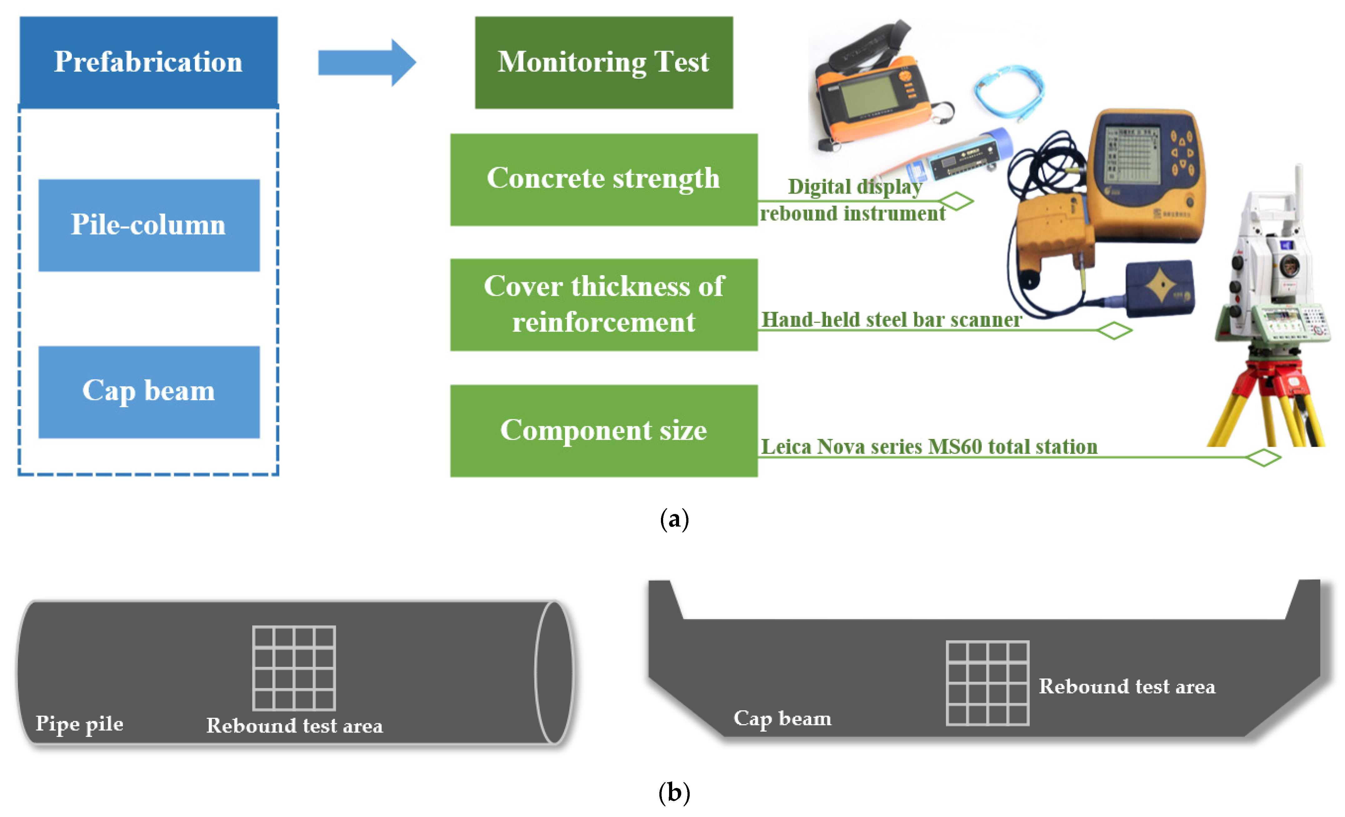
2.3. Non-Destructive Quality Monitoring Methods

Considering that the “pile-column integration” technology of prefabricated bridge structures is a first in China, there is little experience for reference. Through the prepared full-size prefabricated bridge structures in this study, the prefabricated components and quality monitoring results in the “pile-column integration” process of the prefabricated bridge could be tested to whether the prefabricated components meet the requirements. The detailed framework of this study is shown in the below Figure 1a.

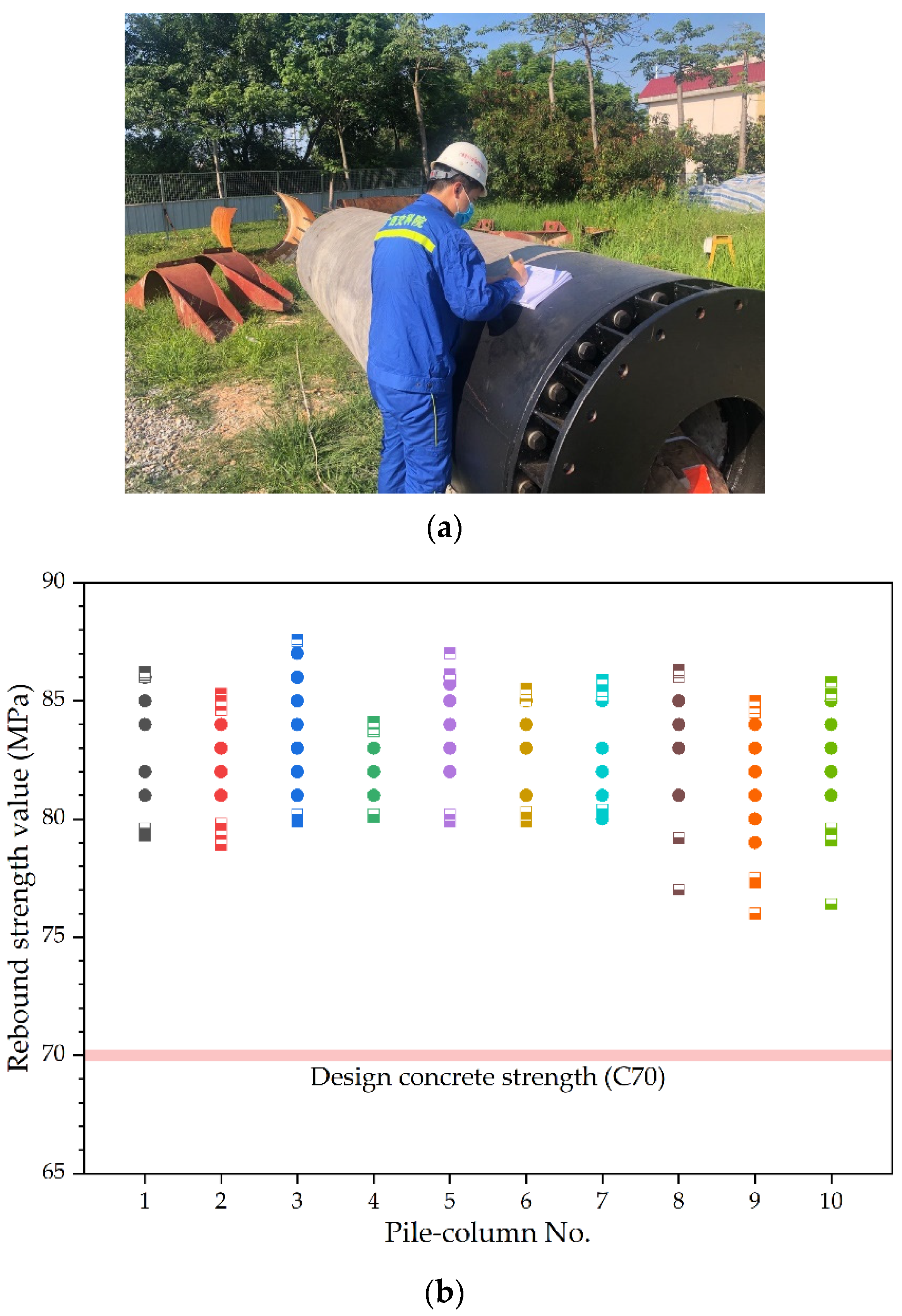
2.3.1. Concrete Strength Monitoring Test Based on Rebound Method

According to “Technical specification for strength testing of high strength concrete” (JGJ/T294-2013) and “Technical specification for inspection of concrete compressive strength by rebound method” (JGJ/T23-2011), the strength of prefabricated pile-column and prefabricated cap beam can be tested by a digital display rebound instrument. The rebound test area of concrete components was firstly selected, as shown in Figure 1b, and the rebound test area should be 20 cm × 20 cm square, in which 16 rebound test points were tested in each rebound test area. After excluding 3 maximum values and 3 minimum values from the 16 rebound test values in each test area, the average rebound test value of each test area could be calculated with the remaining 10 rebound test values by Equation (1).
R = 1 10 i = 1 10 R i ,
where R is the average rebound test value of concrete components at a certain curing age, Ri is the effective rebound test value of the i-th test point.

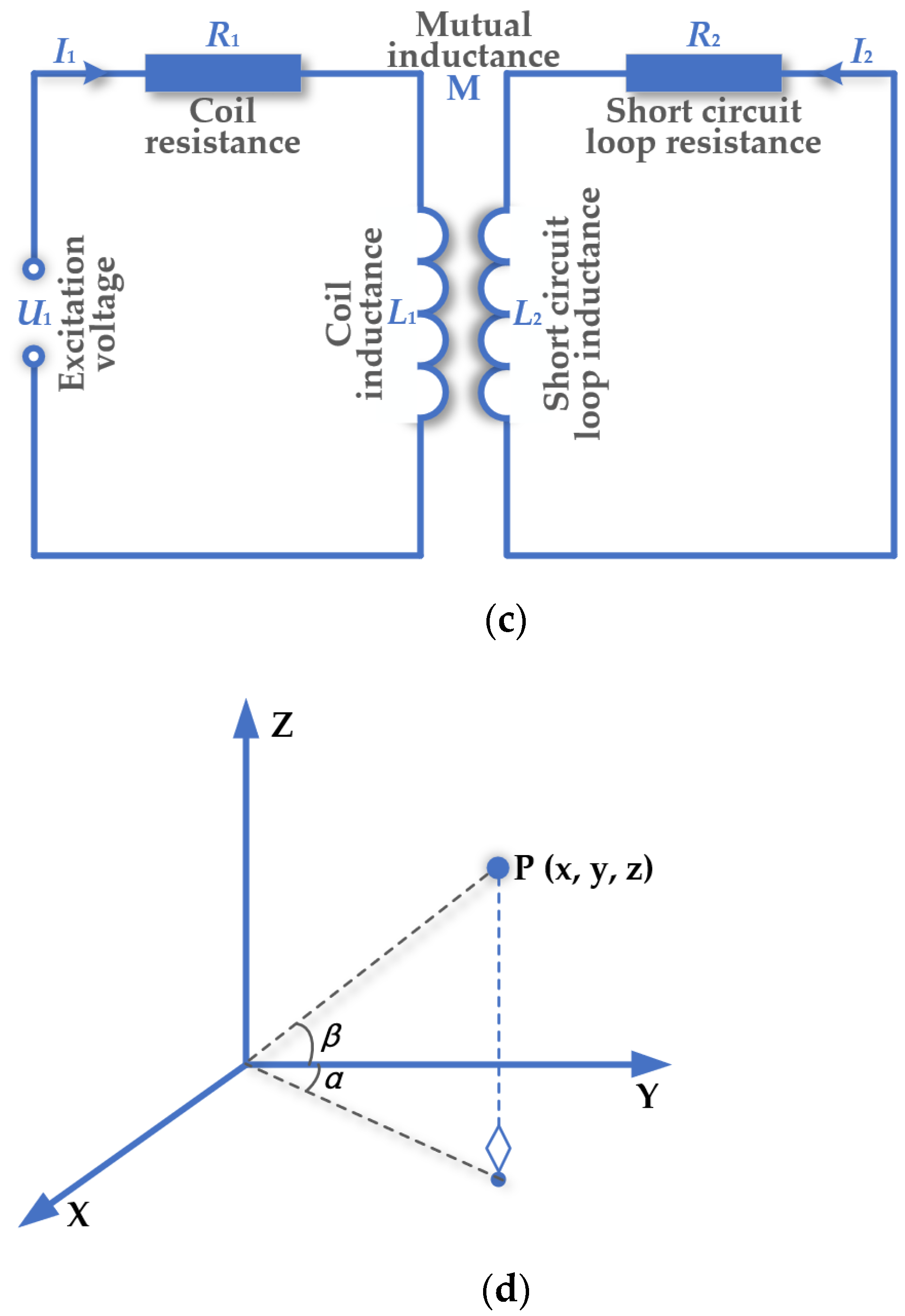
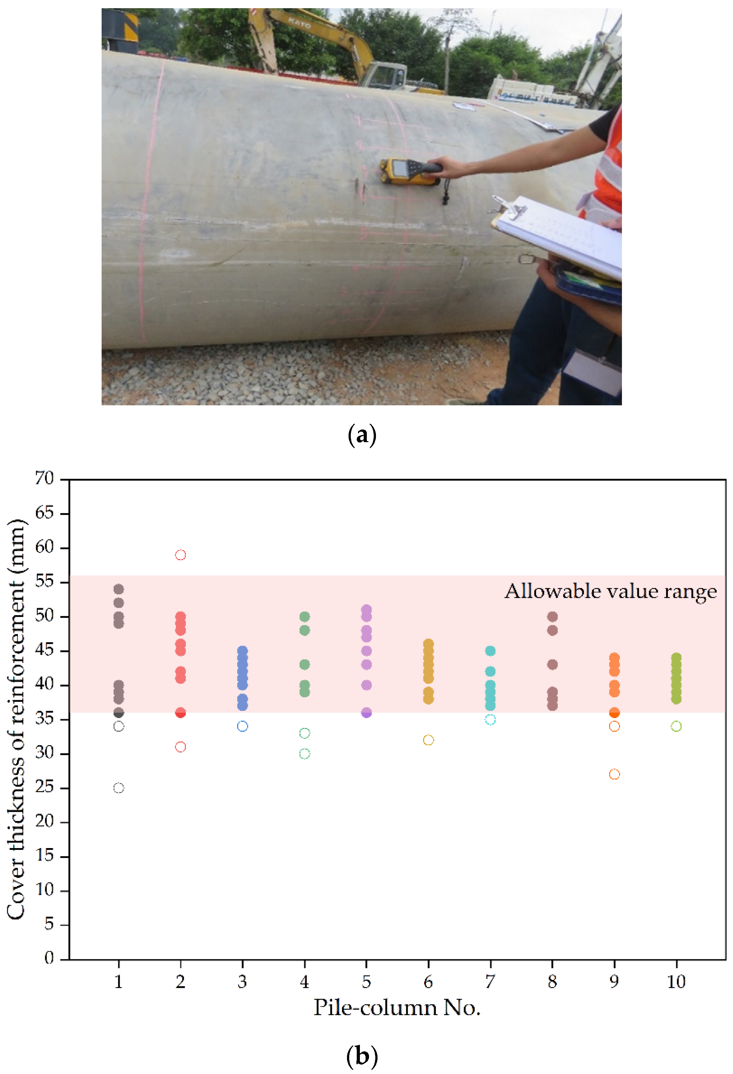
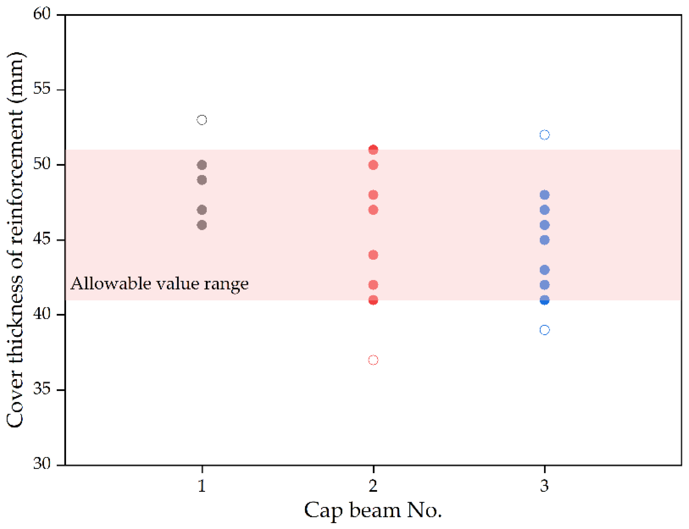
2.3.2. Cover Thickness Monitoring Test of Reinforcement Based on Electromagnetic Induction Method

According to “Technical specification for the test of reinforcing steel bar in concrete” (JGT/T 152-2008), the cover thickness of reinforcement for prefabricated pile-column and prefabricated cap beam could be detected by using a hand-held steel bar scanner. The principle of the electromagnetic induction method is described in Figure 1c: there are two groups of coils in the probe. One group is the magnetic field coil, which generates the magnetic field induced by the pulse signal, and the other group is the induction coil, which induces the change of magnetic induction generated by the steel bar. The host can determine the cover thickness of reinforcement according to the strength of the induced magnetic field by dealing with the change of voltage in the induction coil. Coil impedance (Z) is related to various parameters of metal conductors, as defined in Equation (2).
Z = f(ρ, μ, x, ω),
where ρ is the resistivity, μ is the permeability, x is the distance between coil and conductor, ω is the corresponding angular frequency. It can be seen that when the parameters of the tested material are unchanged, coil impedance is only related to the distance, so the distance between the reinforcement and the tested plane can be deduced.

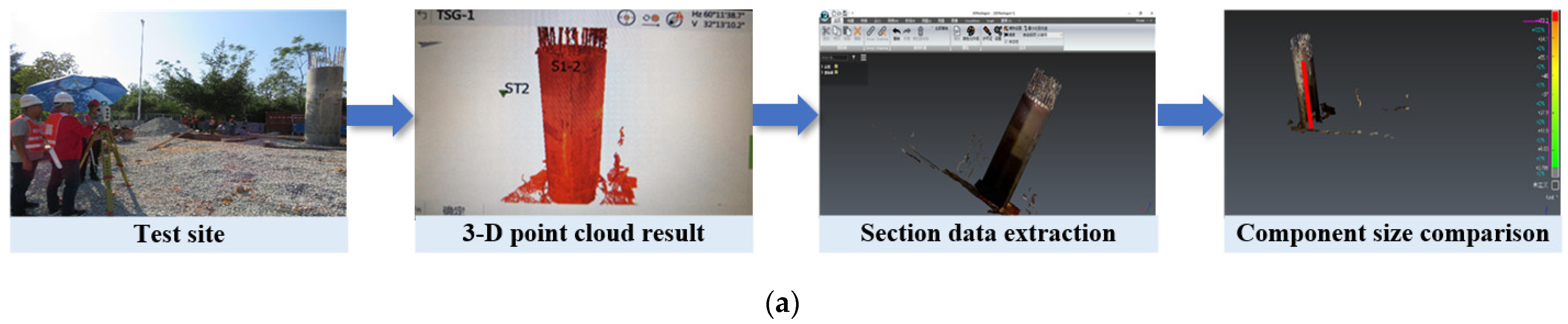
2.3.3. Component Size Monitoring Test Based on 3-D Point Cloud Scanning System

According to “Quality inspection and evaluation standards for highway engineering” (JTG F80-2004), the size and appearance defect inspection of prefabricated bridge components including pile-column and cap beam could be detected by using a Leica Nova series MS60 total station based on 3-D point cloud scanning system. The basic composition of the 3-D MS60 total station is divided into distance measuring devices and angle measuring devices. The space distance between the Leica Nova series MS60 total station and the measured object is measured by emitting a laser through the distance measuring device. The angle measuring device can be used to measure the horizontal angle and vertical angle from the MS60 total station to the measured object. Then, according to the obtained horizontal angle (α), vertical angle (β), and spatial distance (D), the relative position of the measured object relative to the MS60 total station could be calculated, and then the absolute spatial coordinates of the measured object can be obtained by introducing the absolute coordinates. The principle diagram is shown in Figure 1d. Thus, the three-dimensional coordinates of point P can be expressed by the measured three geometric values, i.e., horizontal angle (α), vertical angle (β), and spatial distance (D) by the following equations.
x = Dcosα·cosβ,
y = Dcosα·sinβ,
z = Dsinβ,

3. Prefabrication of Pile-Column and Cap Beam

3.1. Prefabrication and Quality Monitoring of Pile-Column

3.1.1. Prefabrication of Pile-Column

The prefabrication of pile-column is described in Figure 2 as follows:
  • The reinforcement was cut reasonably according to the size requirements to avoid waste. Different grades of reinforcement should not be mixed. Before the framework was formed, the main reinforcement was grouped in equal lengths, of which the relative error of length shall not be greater than L/4000. The spiral stirrup Φ 8.0 high strength cold drawn steel wire was used, which was bound and welded with binding wire. Cage reinforcement was divided into inner and outer layers.
  • The steel mold was disassembled, the cement slag and other residues were cleaned, and the release agent was sprayed. Cage reinforcement was lifted into the steel mold, and the main reinforcement should be straight and parallel to the edge of the steel mold to prevent the cage reinforcement from loosening.
  • The centrifugal forming process could be divided into four stages: low speed—low medium speed—medium speed—high speed. After the pier was centrifuged, the prefabricated samples entered the steam curing pool. The temperature in the pool was set as 30–40 °C, the humidity was ≥95%, and the mold was removed after the total curing time reached 10 h.
  • Demolding was carried out after the strength test met the standard, and it was lifted and placed gently to prevent collision and damage. The concrete slag was cleaned and the appearance defects repaired. The exposed reinforcement with cement slurry was then evenly brushed.

3.1.2. Quality Monitoring of Pile-Column

  • Concrete strength of prefabricated pile-column
The design concrete strength of the prefabricated pile-column in this study is C70, which belongs to high-strength concrete. High-strength concrete has the characteristics of high strength, high brittleness, and poor shrinkage cracking resistance. According to the prefabrication process of pile-column in Figure 2, a total of 10 prefabricated pile-column specimens were prepared. After curing for 30 days, according to Chinese technical specifications, the concrete strength of the prefabricated pile-column was tested by using a digital display rebound instrument. Following the rebound test area of pile-column concrete, the rebound test area with the size of 20 cm × 20 cm was selected, and 16 rebound test points were tested in each rebound test area for these 10 prefabricated pile-column specimens. The concrete strength monitoring test of the prefabricated pile-column using a digital display rebound instrument is shown in Figure 3a.
Based on the measured rebound values of these 10 prefabricated pile-column specimens, three maximum rebound values and three minimum rebound values were excluded from the 16 measured rebound values of each rebound test area. The average rebound test value of each test area could be calculated with the remaining 10 rebound test values through Equation (1), and the average rebound value results of 10 prefabricated pile-column specimens after curing for 30 days are shown in Figure 3b. From Figure 3b, it can be seen that the concrete strength results of all prefabricated pile-column specimens tested by the rebound method are evenly distributed at 80 MPa, and there is little difference. Among these concrete strength values of 10 prefabricated pile-column specimens, a small number of pile-column specimens have respective lower concrete strength values, and most of them are above 80 MPa. Considering that the design concrete strength of the prefabricated pile-column in this study is C70, on the whole, the monitoring results of concrete strength of prefabricated pile-column components in the same batch by rebound method are relatively stable. This is consistent with the findings obtained by Xu et al., that is, the strength values with the coefficient of variation being 7.0% were estimated from the rebound data [33]. The rebound strength results showed that the concrete strength of the prefabricated pile-column components in the same batch were qualified, and the rebound monitoring results of concrete strength of prefabricated pile-column components in the same batch were much higher than the design concrete strength, and their qualified rate were 100%, indicating that the prefabricated pile-column components in this study could meet the design requirements.
  • Cover thickness of reinforcement of prefabricated pile-column
The cover thickness of reinforcement of the prefabricated pile-column is designed as 46 mm in this study. According to the prefabrication process of pile-column, a total of 10 prefabricated pile-column specimens were prepared, and the allowable value range of cover thickness of reinforcement is 36 mm–56 mm. Referring to Chinese technical specifications, the cover thickness of reinforcement of these 10 prefabricated pile-column specimens was tested by using a hand-held steel bar scanner, as shown in Figure 4a.
In this study, the hand-held steel bar scanner was adopted to monitor the longitudinal reinforcement in these 10 prefabricated pile-column specimens at different parts on the side of the test prefabricated component. The design cover thickness value of the longitudinal reinforcement in the prefabricated pile-column components in this study is 46 mm. The measured cover thickness value of the longitudinal reinforcement for 10 prefabricated pile-column specimens is shown in Figure 4b. As seen in Figure 4b, the cover thickness value of the longitudinal reinforcement in 10 prefabricated pile-column specimens measured by the hand-held steel bar scanner are evenly distributed in the allowable value range of cover thickness of reinforcement within 36~56 mm, and there is little difference. Among these cover thicknesses of reinforcement for 10 prefabricated pile-column specimens, a small number of pile-column specimens have respective lower or higher cover thickness values of reinforcement, and most of them are within the allowable value range. On the whole, the monitoring results of cover thickness of reinforcement in prefabricated pile-column components in the same batch by electromagnetic induction method are relatively stable. This view is supported by Kobaka, J. et al. who wrote that this NDT method allowed the detection of the spacing in subsequent layers located in the thickness of the slab [34]. The cover thickness results of reinforcement showed that the cover thickness of reinforcement for the prefabricated pile-column components in the same batch was qualified, and the cover thickness monitoring results of reinforcement of prefabricated pile-column components in the same batch basically fell within the allowable range, and their qualified rates were around 90%, indicating that the prefabricated pile-column components in this study could meet the design requirements of the cover thickness of reinforcement.
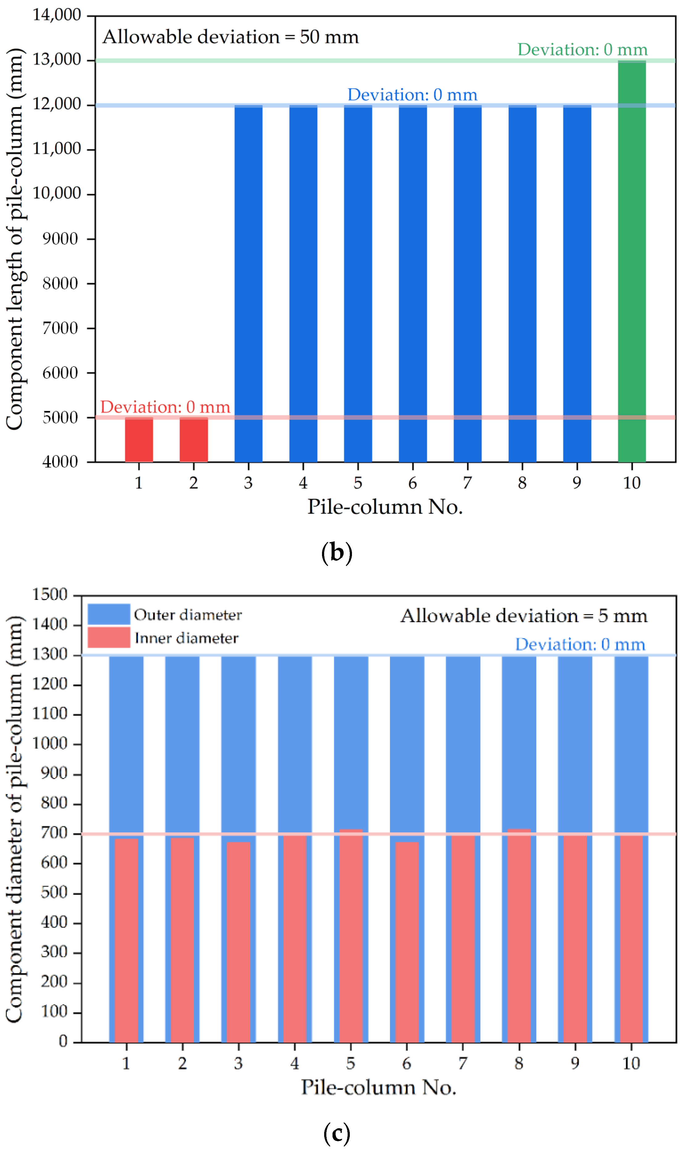
  • Component size of prefabricated pile-column
According to the design and prefabrication process of pile-columns, a total of 10 prefabricated pile-column specimens were prepared, and there are several pile length values of 5 m, 12 m, and 13 m for these pile-column specimens. The design’s outer diameter of pile-column specimen is 1300 mm and the design inner diameter of pile-column specimen is 700 mm. Referring to Chinese technical specifications, the component size of these prefabricated pile-column specimens were tested and monitored by using Leica Nova series MS60 total station combined with a 3-D point cloud scanning system, as shown in Figure 5a.
In this study, these 10 prefabricated pile-column specimens were selected as the test object. Through the method of resection on-site, the component size data of prefabricated pile-column specimens were scanned by using Leica Nova series MS60 total station, in which the scanning mode through polygon range was set as 0.001 m horizontally and 0.001 m vertically. The scanning time of each station was about 5–8 min. The measured component size including outer diameter, inner diameter, and pile length for 10 prefabricated pile-column specimens are shown in Figure 5. It can be seen from Figure 5b that all the pile length values of these 10 prefabricated pile-column specimens measured by the Leica Nova series MS60 total station are distributed in the allowable value range of pile length with the allowable deviation of 50 mm, and their deviation values of these 10 prefabricated pile-column specimens are 0 mm. As seen in Figure 5c, all the outer diameter values of 10 prefabricated pile-column specimens measured by the Leica Nova series MS60 total station are within the allowable deviation of 5 mm, and there is little difference in their deviation values. However, almost half of the inner diameter values of 10 prefabricated pile-column specimens measured by the Leica Nova series MS60 total station are within the allowable deviation of 5 mm, and their deviation values are quite different. On the whole, for the prefabricated pile-column components in the same batch, the pile length and outer diameter measured based on the 3-D point cloud scanning system basically fell within the allowable range, and their qualified rates were around 100%, indicating that the prefabricated pile-column components in this study could meet the design requirements of the pile length and outer diameter. In contrast, about half of the inner diameter measured based on the 3-D point cloud scanning system was within the allowable range, and their qualified rates were about 50%. Similarly, Cui et al. found that the precision of reconstructed surface models obtained by the 3-D point cloud scanning system were mostly larger than 60% [35]. Thus, the monitoring results of component size of prefabricated pile-column in the same batch by 3-D point cloud scanning system were relatively stable when the component size was relatively larger, but the monitoring effect of the 3-D point cloud scanning system still needs to be improved.

3.2. Prefabrication and Quality Monitoring of Cap Beam

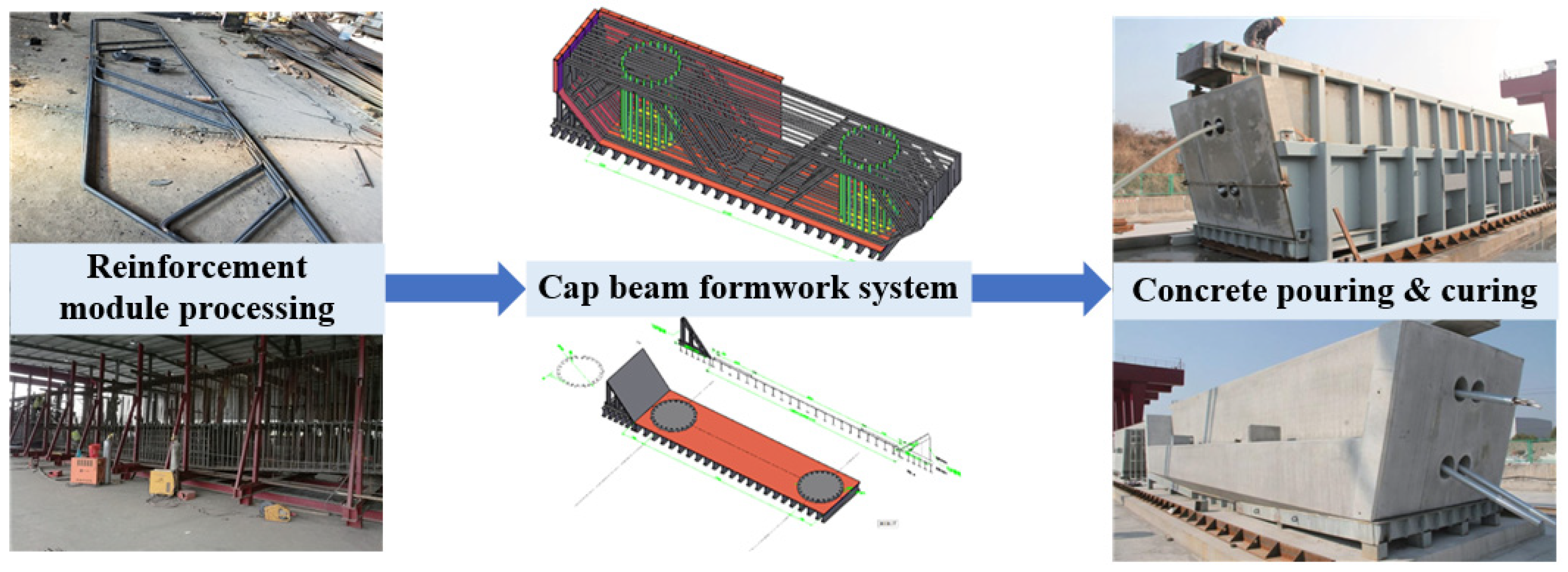
3.2.1. Prefabrication of Cap Beam

The prefabricated cap beam is designed with concrete of grade C40. The prefabrication of the cap beam is described in Figure 6 as follows:
  • The reinforcement cage processing of the cap beam adopted the concept of modular finishing of reinforcement. The Machine Elettroniche Piegatrici (MEP) reinforcement numerical control bending and shearing center is used to cut, bend and straighten the reinforcement.
  • The steel formwork used for prefabricated cap beams requires high processing accuracy, convenient disassembly and assembly of formwork, and reasonable combination. The thickness of the steel plate should not be less than 10 mm, and the finish rolled deformed bar was adopted. Sandblasting and spray painting treatment was carried out in the steel formwork.
  • Concrete of grade C40 was used for the pouring of cap beam, polycarboxylic acid water reducer was used, and the water-cement ratio was controlled within 0.28. Water pipes were used for direct spray curing to ensure the spray curing every 2 h. In high-temperature conditions, geotechnical wetting and covering measures were taken to ensure spray curing at least once every 1 h.

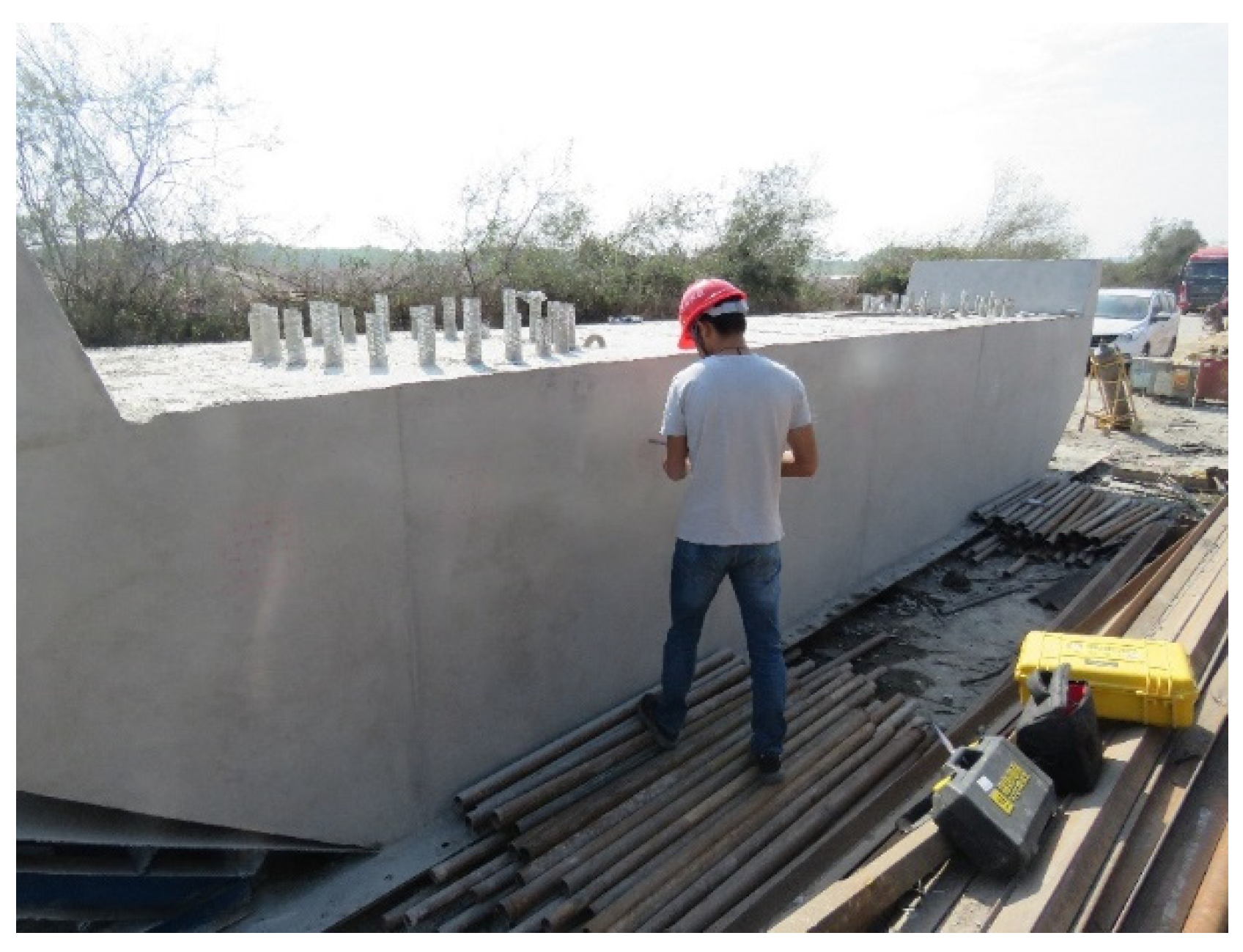
3.2.2. Quality Monitoring of Cap Beam

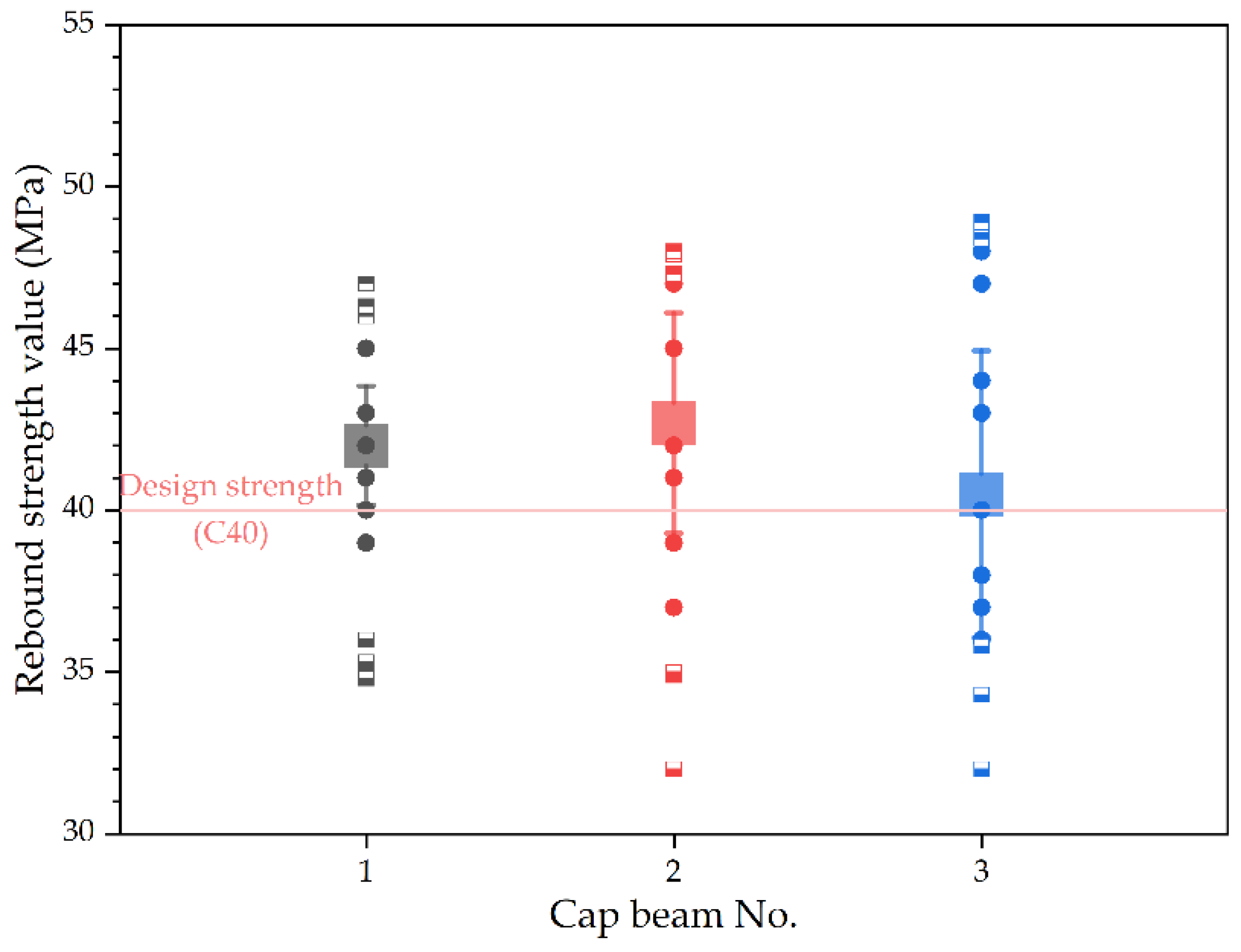
  • Concrete strength of prefabricated cap beam.
The design concrete strength of the prefabricated cap beam in this study is C40, and a total of 3 prefabricated cap beam specimens were prepared according to the prefabrication process of the cap beam in Figure 6. After curing for 30 days, according to Chinese technical specifications, the concrete strength of the prefabricated cap beam was tested by using a digital display rebound instrument. Following the rebound test area of cap beam concrete, the rebound test area with the size of 20 cm × 20 cm was selected, and 16 rebound test points were tested in each rebound test area for the prefabricated cap beam specimens. The concrete strength monitoring test of a prefabricated cap beam using a digital display rebound instrument is shown in Figure 7.
Three maximum rebound values and three minimum rebound values were excluded from the 16 measured rebound values of each rebound test area for 3 prefabricated cap beam specimens. The average rebound test value of each test area could be calculated with the remaining 10 rebound test values through Equation (1), and the average rebound value results of 3 prefabricated cap beam specimens after curing for 30 days are shown in Figure 8. In Figure 8, it can be seen that the concrete strength results of all prefabricated cap beam specimens tested by the rebound method are evenly distributed in the range of 30–50 MPa. Among these concrete strength values of three prefabricated cap beam specimens, there is a large difference, and the corresponding average rebound values are above 40 MPa. As discussed above, the monitoring results of concrete strength of prefabricated cap beam components in the same batch by rebound method were relatively stable. The qualified rate of concrete strength of prefabricated cap beam components in the same batch was 100%, indicating that the prefabricated cap beam components in this study could meet the design requirements.
  • Cover thickness of reinforcement of prefabricated cap beam.
The cover thickness of the longitudinal reinforcement of the prefabricated cap beam is designed as 46 mm in this study. According to the prefabrication process of the cap beam, a total of 3 prefabricated cap beam specimens were prepared, and the allowable value range of cover thickness of reinforcement is 41~51 mm. Referring to Chinese technical specifications, the cover thickness of the longitudinal reinforcement of these prefabricated cap beam specimens was tested at different parts by using a hand-held steel bar scanner. The measured cover thickness value of the longitudinal reinforcement for prefabricated cap beam specimens is shown in Figure 9. Most cover thickness values of the longitudinal reinforcement in prefabricated cap beam specimens measured by the hand-held steel bar scanner were evenly distributed in the allowable value range of 41–51 mm. Among these cover thicknesses of reinforcement for the prefabricated cap beam specimens, only several cap beam specimens have respective lower or higher cover thickness values of reinforcement. On the whole, the monitoring results of the cover thickness of reinforcement in prefabricated cap beam components in the same batch by electromagnetic induction method were relatively stable. The cover thickness monitoring results of reinforcement of prefabricated cap beam components in the same batch fell within the allowable range, and their qualified rates were around 90%, indicating that the prefabricated cap beam components in this study could meet the design requirements of the cover thickness of reinforcement. This result is supported by Kobaka et al. [34].
  • Component size of prefabricated cap beam.
The design length, width, and height of the cap beam specimens are 8500 mm, 1700 mm, and 1450 mm according to the design and prefabrication process of the cap beam. Referring to Chinese technical specifications, the component size of the prefabricated cap beam was tested and monitored by using the Leica Nova series MS60 total station combined with a 3-D point cloud scanning system. The measured component size results of the prefabricated cap beam specimens are shown in Figure 10. The allowable deviation of length for the prefabricated cap beam is 50 mm, and the allowable deviation of width, height, and corrugated pipe diameter for the prefabricated cap beam is 5 mm. It can be seen from Figure 10 that all the length and width values of the prefabricated cap beam specimens measured by the Leica Nova series MS60 total station are distributed in the corresponding allowable value ranges. For the prefabricated cap beam components in the same batch, the length and width measures based on the 3-D point cloud scanning system basically fell within the allowable range, and their qualified rates were around 100%, indicating that the prefabricated cap beam in this study could meet the design requirements of the length and width. However, based on the 3-D point cloud scanning system, the qualified rates of height and corrugated pipe diameter were 67% and 33%, respectively, which is consistent with the findings obtained by Cui et al. [35].

4. Conclusions

Based on the assembly process of “pile-column integration”, the full-scale bridge substructure, including pile column and cap beam, was reasonably designed and prefabricated. Then the quality monitoring of full-scale prefabricated bridge substructure for “pile-column integration” was carried out based on a series of nondestructive testing technologies. From the test results, the following conclusions were drawn:
(1)
The concrete strength monitoring results of prefabricated components by the rebound method are relatively stable. The concrete strength of the prefabricated components was higher than the design concrete strength and their qualified rate was 100%, indicating that the prefabricated components could meet the design requirements.
(2)
According to the monitoring of cover thickness of reinforcement, the cover thickness values of reinforcement in prefabricated components by electromagnetic induction method were relatively stable, the cover thickness of reinforcement basically fell within the allowable range, and their qualified rates were around 90%.
(3)
The component size of the prefabricated components could be tested by a 3-D point cloud scanning system. When the component size was relatively larger, the monitoring results of component size of prefabricated components by the 3-D point cloud scanning system were relatively stable, but the monitoring effect of the 3-D point cloud scanning system still needs to be improved.
(4)
The quality monitoring of full-scale bridge substructures for “pile-column integration” proved the rationality of prefabrication and the feasibility of non-destructive testing technologies, providing references for the application of “pile-column integration”.

Author Contributions

Conceptualization, L.W., H.W. and K.Y.; methodology, L.W., H.W. and W.W.; validation, S.X., G.W. and R.L.; formal analysis, L.W., H.W. and W.W.; investigation, K.Y., S.X., G.W. and R.L.; writing—original draft preparation, L.W. and H.W.; writing—review and editing, K.Y. and W.W.; project administration, H.W. and W.W.; funding acquisition, H.W. and W.W. All authors have read and agreed to the published version of the manuscript.

Funding

This research was funded by the Science and Technology Base and Talent Special Project of Guangxi Province, grant number AD19245152, Science and Technology Key R&D Project of Guangxi, grant number AB22035074, “Yongjiang Plan” of Nanning Leading Talents in Innovation and Entrepreneurship, grant number 2018-01-04, National Key R&D Program of China, grant number 2021YFB2600604, High-Level Entrepreneurship and Innovation Talents Project of Nanning High Tech Zone, grant number 2020008, China Postdoctoral Science Foundation, grant number 2021T140262, Scientific and Technological Project of Science and Technology Department of Jilin Province, grant number 20210508028RQ, and Scientific Research Project of Department of Education of Jilin Province, grant number JJKH20221019KJ.

Institutional Review Board Statement

Not applicable.

Informed Consent Statement

Not applicable.

Data Availability Statement

Not applicable.

Conflicts of Interest

The authors declare no conflict of interest.

References

  1. Serra, M.; Festa, G.; Vassallo, M.; Zollo, A.; Quattrone, A.; Ceravolo, R. Damage detection in elastic properties of masonry bridges using coda wave interferometry. Struct. Control Health Monit. 2017, 24, e1976. [Google Scholar] [CrossRef]
  2. Liu, H.B.; Wang, H.; Tan, G.J.; Wang, W.S.; Liu, Z.Y. Effect of temperature and spring-mass systems on modal properties of timoshenko concrete beam. Struct. Eng. Mech. 2018, 65, 389–400. [Google Scholar]
  3. Jiang, G.F.; Liang, Q.X.; Wang, H.; Ju, Y.C.; Wang, H.H.; Wang, X.R.; Wang, L.L.; Wang, W.S. Study on evaluation theory of bridge damage state and methodology on early-warning of danger. Adv. Mater. Sci. Eng. 2021, 2021, 6636959. [Google Scholar] [CrossRef]
  4. Yi, T.Y.; Wang, H.; Xie, J.T.; Wang, W.S. Flexural strength and acoustic damage characteristics of steel bar reactive powder concrete. Appl. Sci. 2021, 11, 7017. [Google Scholar] [CrossRef]
  5. Wang, X.R.; Wang, L.L.; Wang, H.; Ning, Y.H.; Huang, K.N.; Wang, W.S. Performance evaluation of a long-span cable-stayed bridge using non-destructive field loading tests. Appl. Sci. 2022, 12, 2367. [Google Scholar] [CrossRef]
  6. Wang, H.; Wang, L.L.; Zhuo, X.L.; Huang, K.N.; Wang, X.R.; Wang, W.S. Study on the precise displacement controlling method for a suspended deck in the hanger replacement process of an arch bridge. Appl. Sci. 2021, 11, 9607. [Google Scholar] [CrossRef]
  7. Saleem, M.A.; Zafar, M.N.; Saleem, M.M.; Xia, J. Recent developments in the prefabricated bridge deck systems. Case Stud. Constr. Mater. 2021, 15, e00750. [Google Scholar] [CrossRef]
  8. Xia, L.L.; Hu, Z.J.; Shah, Y.I. Longitudinal load distribution of a weakly connected prefabricated bridge abutment. Arch. Appl. Mech. 2021, 91, 4121–4140. [Google Scholar] [CrossRef]
  9. Shim, C.S.; Dang, S.N.; Park, S. Three-dimensional information delivery for design and construction of prefabricated bridge piers. Struct. Eng. Int. 2018, 28, 6–12. [Google Scholar] [CrossRef]
  10. Ryu, H.K.; Kim, Y.J.; Chang, S.P. Crack control of a continuous composite two-girder bridge with prefabricated slabs under static and fatigue loads. Eng. Struct. 2007, 29, 851–864. [Google Scholar] [CrossRef]
  11. Haider, M.A.; Batikha, M.; Elhag, T. Precast versus cast in-situ concrete in the construction of post-tensioned box-girder bridges: Span effect. Struct. Concr. 2020, 21, 56–64. [Google Scholar] [CrossRef]
  12. Moyo, P.; Sibanda, B.; Beushausen, H. Modelling and integrity assessment of shear connectors in precast cast-in-situ concrete bridges. Struct. Eng. Mech. 2012, 42, 55–72. [Google Scholar] [CrossRef]
  13. Kurylowicz-Cudowska, A. Determination of thermophysical parameters involved in the numerical model to predict the temperature field of cast-in-place concrete bridge deck. Materials 2019, 12, 3089. [Google Scholar] [CrossRef] [PubMed] [Green Version]
  14. Jensen, T.W.; Poulsen, P.N.; Hoang, L.C. Limit analysis of reinforced concrete slabs with construction joints. Eng. Struct. 2020, 205, 110062. [Google Scholar] [CrossRef]
  15. Fasching, S.; Huber, T.; Rath, M.; Kollegger, J. Semi-precast segmental bridges: Development of a new construction method using thin-walled prefabricated concrete elements. Struct. Concr. 2021, 22, 1561–1573. [Google Scholar] [CrossRef]
  16. Suffner, A.; Schulze, T. Green bridges from prefabricated arch-segments. Bautechnik 2016, 93, 98–101. [Google Scholar] [CrossRef]
  17. Koem, C.; Shim, C.S.; Park, S.J. Seismic performance of prefabricated bridge columns with combination of continuous mild reinforcements and partially unbonded tendons. Smart Struct. Syst. 2016, 17, 541–557. [Google Scholar] [CrossRef]
  18. Billington, S.L.; Barnes, R.W.; Breen, J.E. A precast segmental substructure system for standard bridges. PCI J 1999, 44, 56–73. [Google Scholar] [CrossRef]
  19. Zhuo, W.D.; Tong, T.; Liu, Z. Analytical pushover method and hysteretic modeling of precast segmental bridge piers with high-strength bars based on cyclic loading test. J. Struct. Eng. 2019, 145, 04019050. [Google Scholar] [CrossRef]
  20. ElGawady, M.A.; Dawood, H.M. Analysis of segmental piers consisted of concrete filled frp tubes. Eng. Struct. 2012, 38, 142–152. [Google Scholar] [CrossRef]
  21. Peeters, B.; Couvreur, G.; Razinkov, O.; Kundig, C.; Van der Auweraer, H.; De Roeck, G. Continuous monitoring of the oresund bridge: System and data analysis. Struct. Infrastruct. Eng. 2009, 5, 395–405. [Google Scholar] [CrossRef]
  22. Park, J.; Choi, J.; Jang, Y.; Park, S.K.; Hong, S. An experimental and analytical study on the deflection behavior of precast concrete beams with joints. Appl. Sci. 2017, 7, 1198. [Google Scholar] [CrossRef] [Green Version]
  23. Hong, J.K.; Shen, G.Q.P.; Li, Z.D.; Zhang, B.Y.; Zhang, W.Q. Barriers to promoting prefabricated construction in china: A cost-benefit analysis. J. Clean. Prod. 2018, 172, 649–660. [Google Scholar] [CrossRef]
  24. Jiang, L.; Li, Z.F.; Li, L.; Gao, Y.L. Constraints on the promotion of prefabricated construction in china. Sustainability 2018, 10, 2516. [Google Scholar] [CrossRef] [Green Version]
  25. Wu, Q.H.; Qiu, Z.Z.; Niu, Z. Study on the factory prefabrication technology of large-span bridges pier. Appl. Mech. Mater. 2014, 501–504, 1413–1417. [Google Scholar] [CrossRef]
  26. Li, F.Y.; Shen, Y. Full-scale test of the hydration heat and the curing method of the wet joints of a precast segmental pier of a bridge. Eur. J. Environ. Civ. Eng. 2017, 21, 348–370. [Google Scholar] [CrossRef]
  27. Chen, R.F.; Tan, Y.; Zhang, B.L.; Shen, W.G.; Liu, G.L.; Wang, Z.W. Installation of integral prefabricated bridge abutment and pier with flexible water stop curtain. J. Constr. Eng. Manag. 2018, 144, 04018087. [Google Scholar] [CrossRef]
  28. Wu, D.J.; Xiong, W.; Guo, J.M. Establishment and repetition survey of primary gnss control network of hong kong-zhuhai-macao bridge. J. Surv. Eng. 2022, 148, 05021006. [Google Scholar] [CrossRef]
  29. Yan, X.Z.; Zhang, H.; Zhang, W.Y. Intelligent monitoring and evaluation for the prefabricated construction schedule. Comput. Civ. Infrastruct. Eng. 2022. [Google Scholar] [CrossRef]
  30. Worley, R.; Dewoolkar, M.M.; Xia, T.; Farrell, R.; Orfeo, D.; Burns, D.; Huston, D.R. Acoustic emission sensing for crack monitoring in prefabricated and prestressed reinforced concrete bridge girders. J. Bridg. Eng. 2019, 24, 04019018. [Google Scholar] [CrossRef] [Green Version]
  31. Tsangouri, E.; Remy, O.; Boulpaep, F.; Verbruggen, S.; Livitsanos, G.; Aggelis, D.G. Structural health assessment of prefabricated concrete elements using acoustic emission: Towards an optimized damage sensing tool. Constr. Build. Mater. 2019, 206, 261–269. [Google Scholar] [CrossRef]
  32. Fan, J.J.; Feng, D.C.; Wu, G.; Hou, S.T.; Lu, Y. Experimental study of prefabricated rc column-foundation assemblies with two different connection methods and using large-diameter reinforcing bars. Eng. Struct. 2020, 205, 110075. [Google Scholar] [CrossRef]
  33. Xu, T.Z.; Li, J. Assessing the spatial variability of the concrete by the rebound hammer test and compression test of drilled cores. Constr. Build. Mater. 2018, 188, 820–832. [Google Scholar] [CrossRef]
  34. Kobaka, J.; Katzer, J.; Ponikiewski, T. A combined electromagnetic induction and radar-based test for quality control of steel fibre reinforced concrete. Materials 2019, 12, 3507. [Google Scholar] [CrossRef] [Green Version]
  35. Cui, Y.; Li, Q.Q.; Yang, B.; Xiao, W.; Chen, C.; Dong, Z. Automatic 3-d reconstruction of indoor environment with mobile laser scanning point clouds. IEEE J. Sel. Top. Appl. Earth Obs. Remote Sens. 2019, 12, 3117–3130. [Google Scholar] [CrossRef] [Green Version]
Figure 1. Non-destructive quality monitoring methods of full-size prefabrication and monitoring of bridge components for “Pile-Column Integration: (a) study framework; (b) the rebound test area of prefabricated concrete components for “Pile-Column Integration”; (c) schematic diagram of eddy current equivalent circuit; (d) the principle diagram of point position calculation.
Buildings 12 00715 g001aBuildings 12 00715 g001b
Figure 2. The prefabrication process of pile-column.
Buildings 12 00715 g002
Figure 3. Concrete strength of prefabricated pile-column: (a) the concrete strength monitoring test of a prefabricated pile-column using a digital display rebound instrument; (b) the rebound values of 10 prefabricated pile-columns after curing for 30 days.
Buildings 12 00715 g003
Figure 4. Cover thickness of reinforcement of prefabricated pile-column: (a) the cover thickness monitoring test of a prefabricated pile-column using a hand-held steel bar scanner; (b) the cover thickness values of reinforcement for 10 prefabricated pile-column specimens.
Buildings 12 00715 g004
Figure 5. The component size monitoring for 10 prefabricated pile-column specimens: (a) The component size monitoring test of a prefabricated pile-column using Leica Nova series MS60 total station; (b) Pile length monitoring results and (c) Outer and inner diameter monitoring results.
Buildings 12 00715 g005aBuildings 12 00715 g005b
Figure 6. The prefabrication process of cap beam.
Buildings 12 00715 g006
Figure 7. The concrete strength monitoring test of a prefabricated cap beam using a digital display rebound instrument.
Buildings 12 00715 g007
Figure 8. The rebound values of prefabricated cap beams after curing for 30 days.
Buildings 12 00715 g008
Figure 9. The cover thickness values of reinforcement for prefabricated cap beam specimens.
Buildings 12 00715 g009
Figure 10. The component size values of prefabricated cap beam specimens.
Buildings 12 00715 g010
Table 1. Properties of concrete used in this study.
ParametersElastic Modulus (MPa)Bulk Density (kN/m3)Axial Compression Strength Design fcd (MPa)Axial Tension Strength Design ftd (MPa)Poisson’s RatioLinear Expansion Coefficient (°C)
C703.75 × 1042630.52.100.21.0 × 10−5
C503.45 × 1042622.41.830.21.0 × 10−5
C403.25 × 1042618.41.650.21.0 × 10−5
C303.00 × 1042613.81.390.21.0 × 10−5
Table 2. Properties of reinforcement used in this study.
ParametersElastic Modulus Es (MPa)Tensile Design Strength fsd (MPa)Standard Strength fsk (MPa)
HPB3002.1 × 105195300
HPB4002.0 × 105280400
Publisher’s Note: MDPI stays neutral with regard to jurisdictional claims in published maps and institutional affiliations.

