
Automated Selection and Localization of Mobile Cranes in Construction Planning


Abstract
:1. Introduction
2. Literature Review
2.1. Crane Selection
2.2. Crane Localization
2.3. Research Gaps
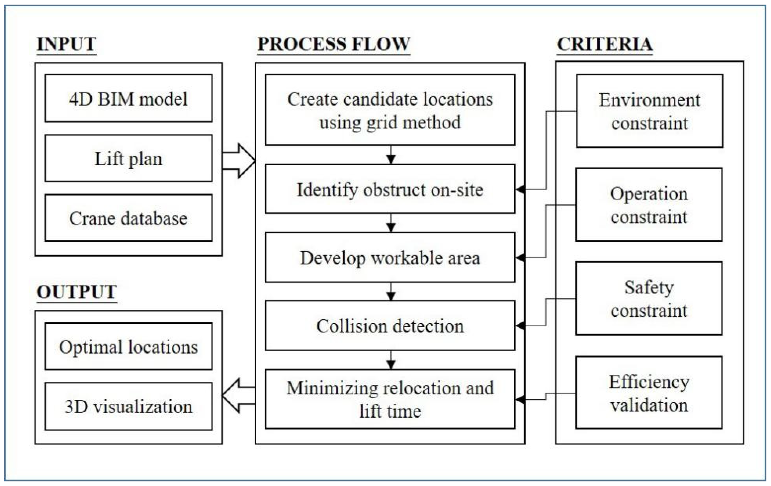
3. Methodology
4. Method for Automated Selection and Localization of a Crane
4.1. Information Requirement and Extraction
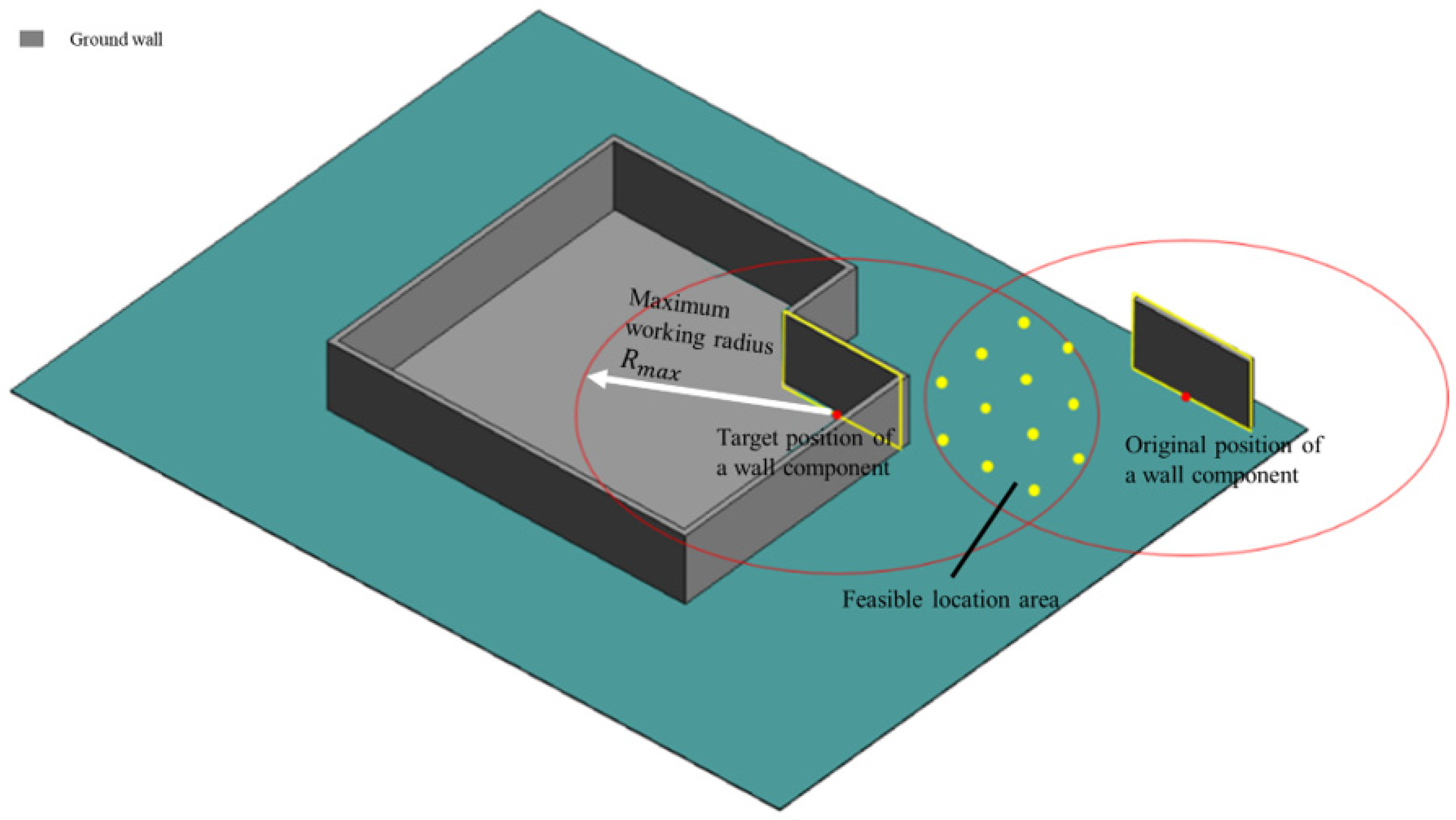
4.2. Initial Type Selection and Candidate Location Generation
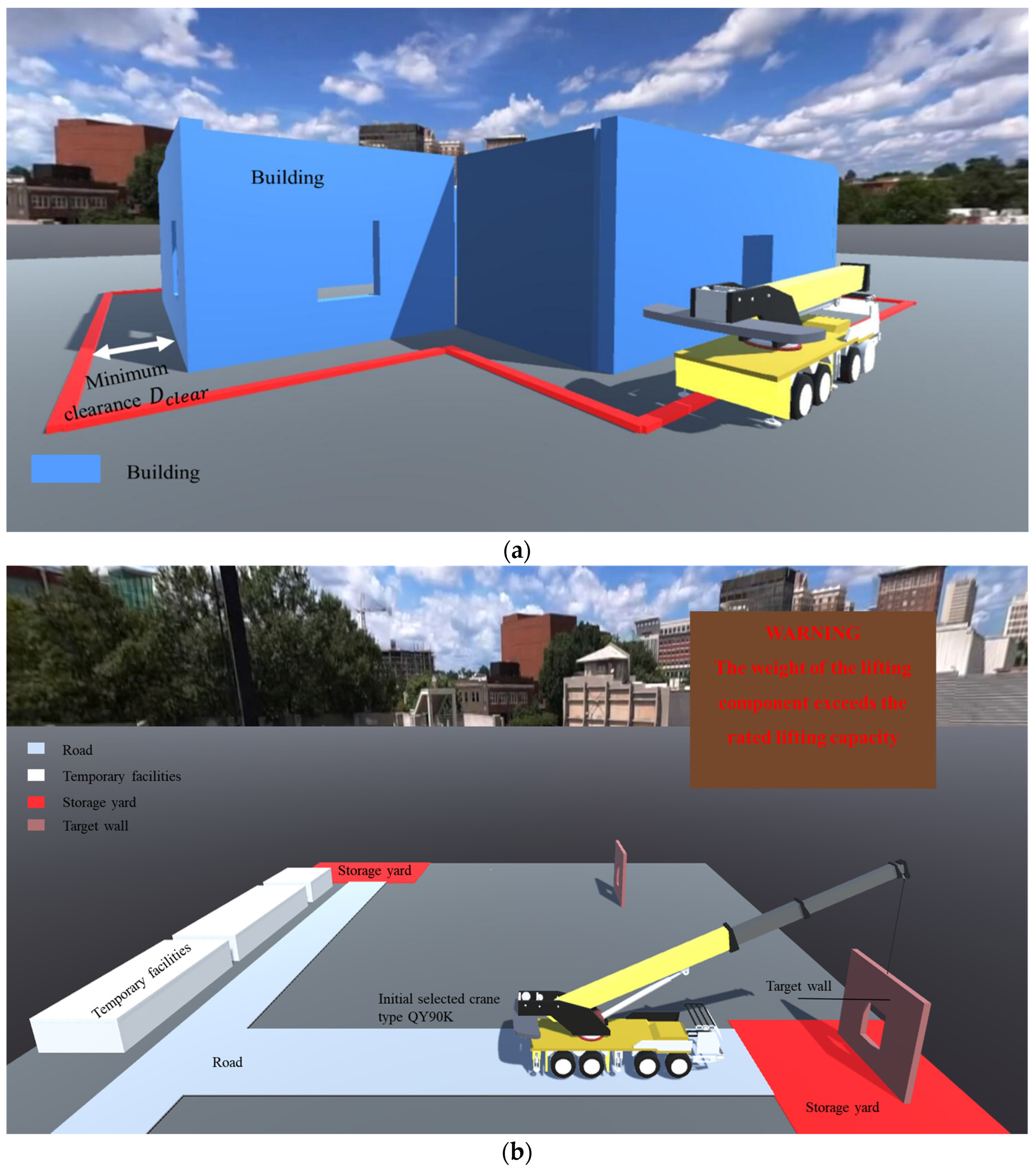
4.3. Environment Constraint Check
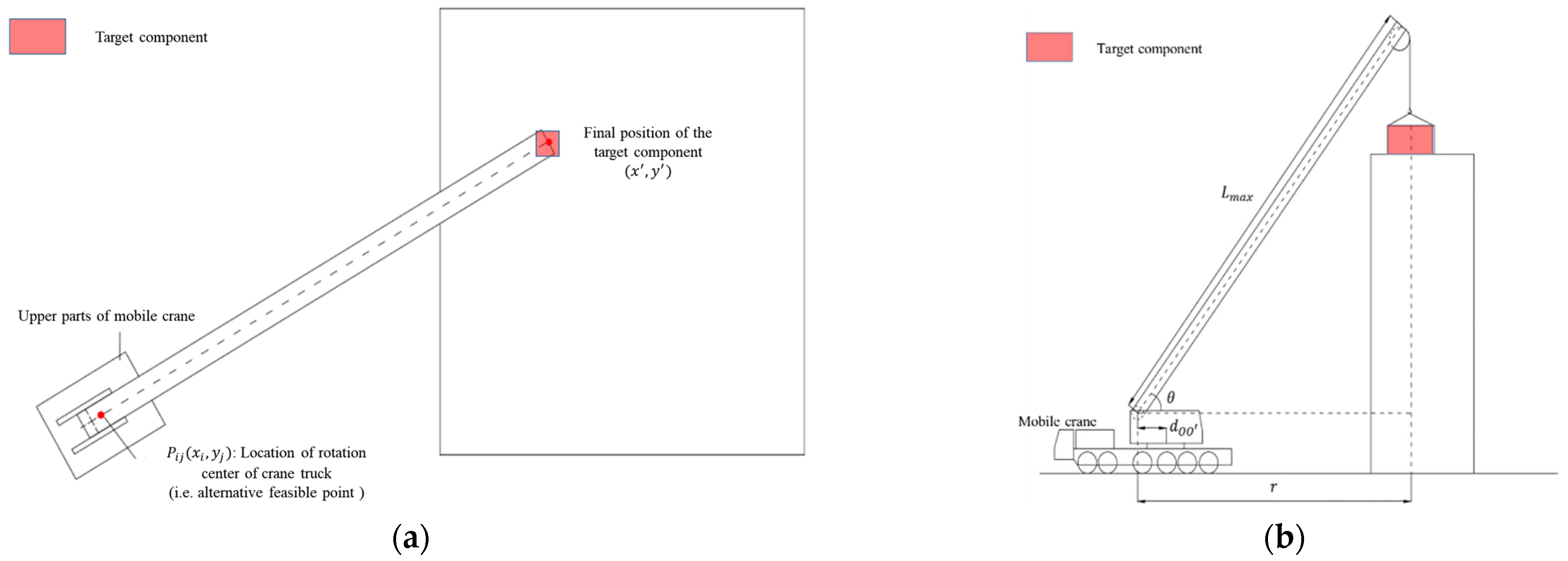
4.4. Operation Constraint Check
- For a column component, its position coordinates in the BIM model are its bottom center coordinates. Thus, only the z-axis coordinate needs to be re-calculated to determine its target position coordinates. Taking column C1 as an example, based on its position coordinates in the BIM model and its height H and floor height HF obtained from the BIM model, the coordinates of its gravity center are determined as .
- For a regular rectangular slab, the coordinates of its gravity center can be calculated from the coordinates of each endpoint of the slab in the model. Taking slab P as an example, based on two diagonal endpoint coordinates and , the height H, the floor height HF, and the slab depth D from the BIM model, the coordinates of its gravity center are .
- For wall and beam components in the form of tension, since the position coordinates in the BIM model are the coordinates of the tension starting point, it is necessary to determine the changed plane coordinates of its gravity center. Taking the wall W1 as an example, based on the starting point coordinates , direction , length L, height H, and floor height HF from the BIM model, the coordinates of its gravity center can be calculated using Equation (5):
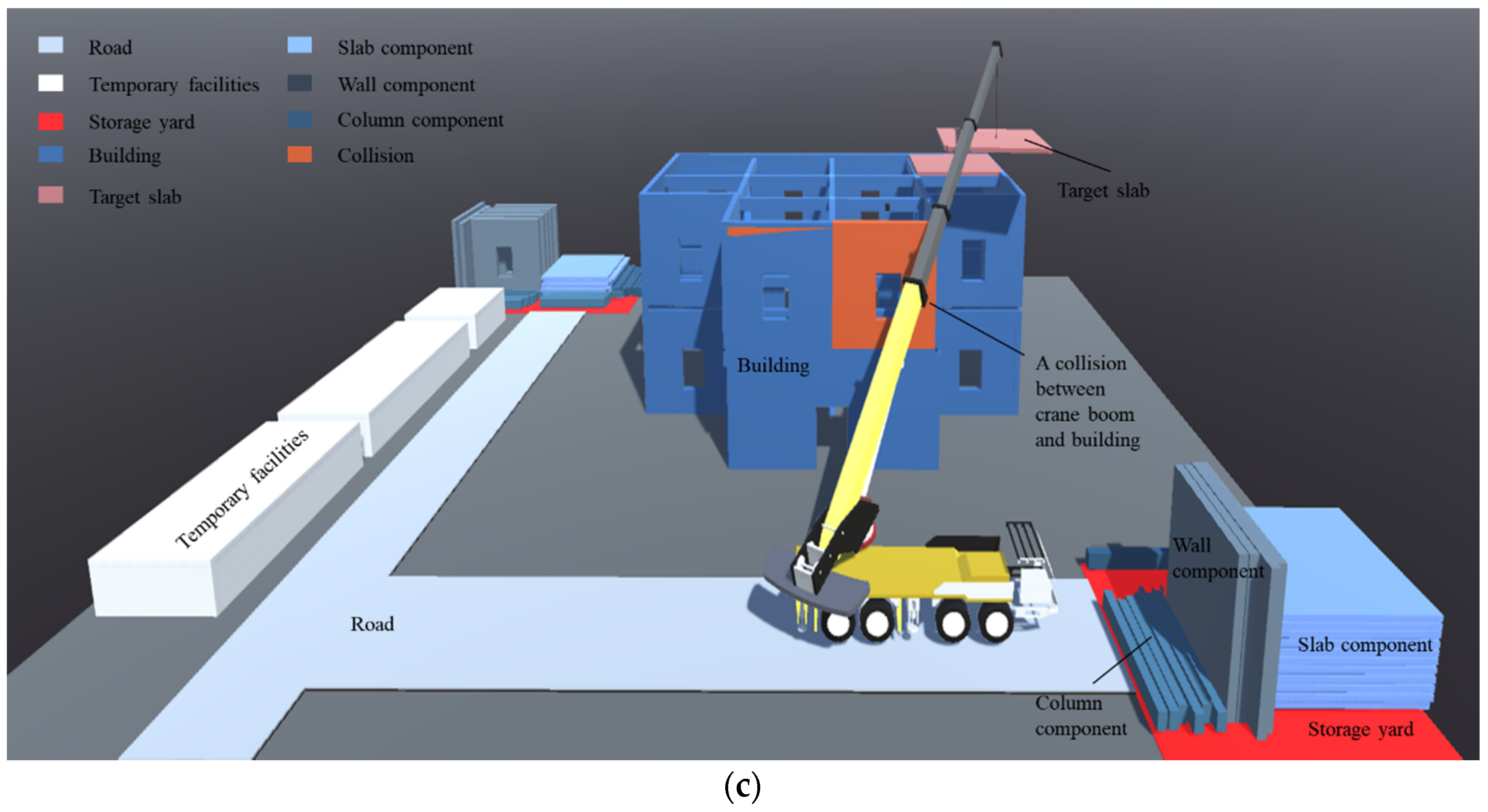
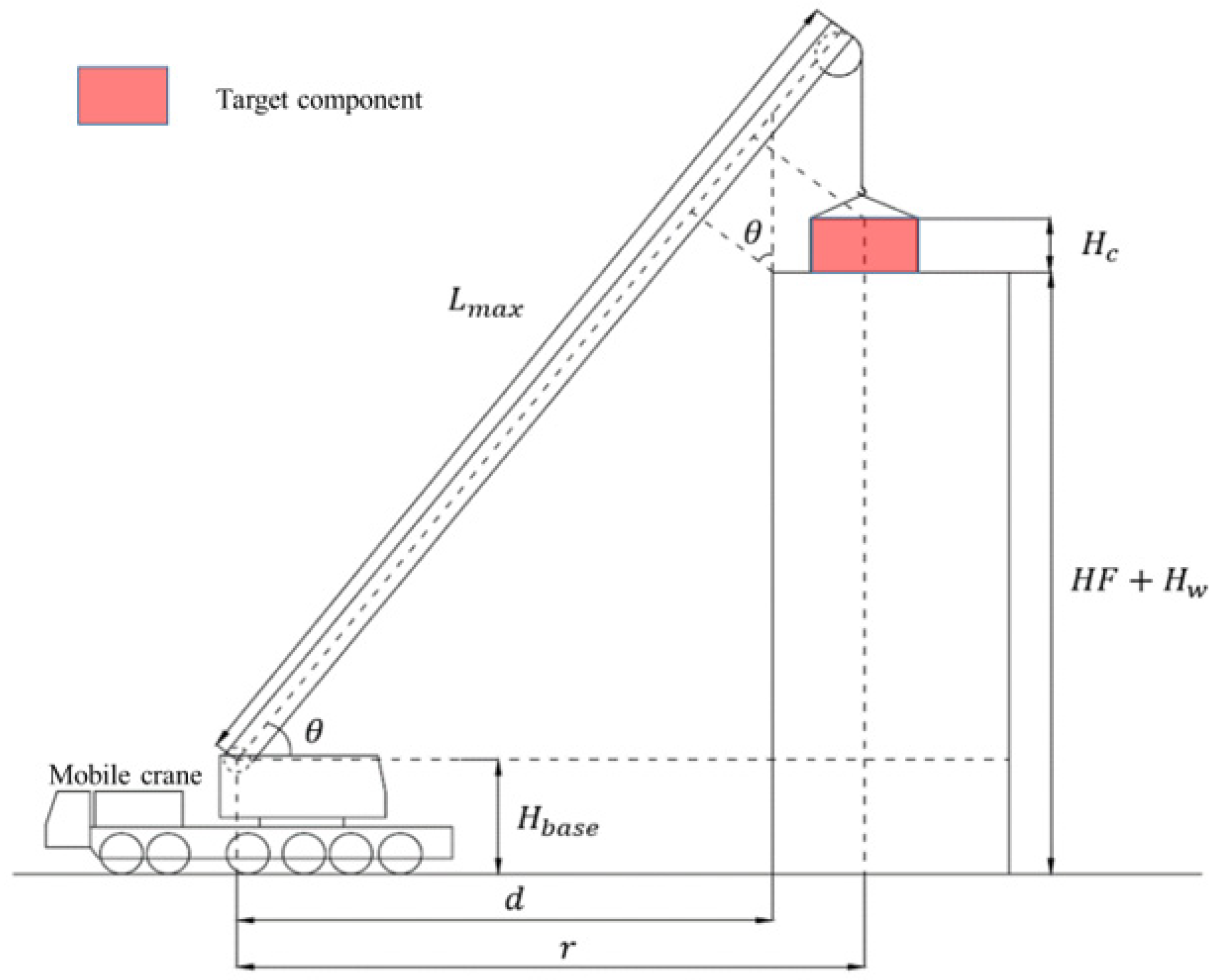
4.5. Safety Constraint Check
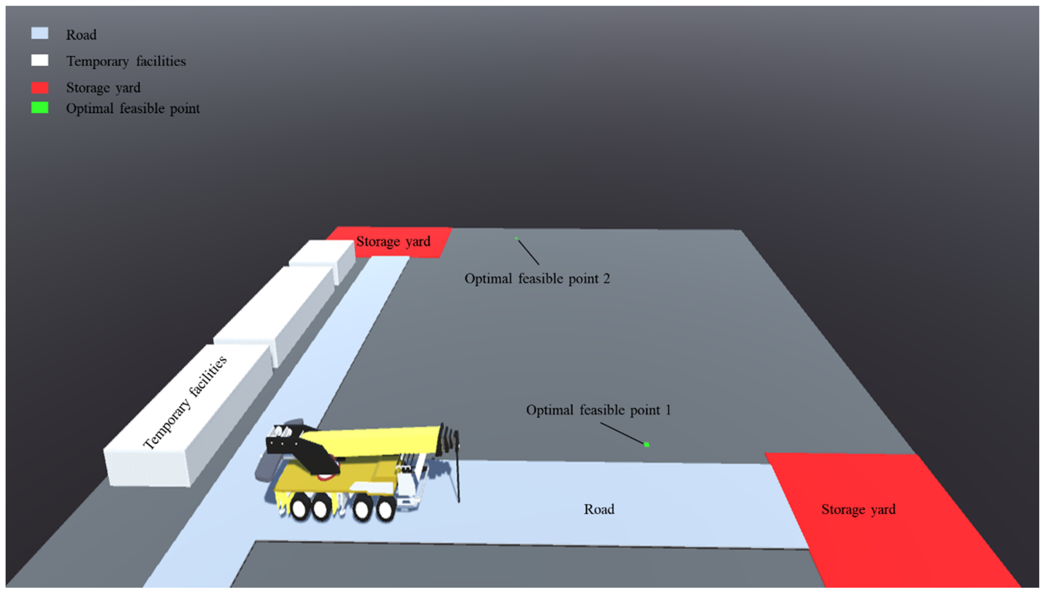
4.6. Lifting Efficiency Optimization
- (1)
- Minimization of single lifting time
- (2)
- Minimization of relocation times
- Check the attribute value k of each feasible point in turn, and add points with the same attribute to the same group.
- Find the group Groupm that contains the most contiguous attributes. Since the attribute value k is the number of components and also represents the lifting order of components, the lifting order should be considered to ensure that the attribute value is as continuous as possible.
- Compare the minimum lifting time when the crane is located at the points of multiple Groupm, and select the group with the shortest lifting time as the final Groupm. If no multiple Groupm exist, go straight to the next step.
- Take point in Groupm as the location point of the crane for the hoist of the component , and release the attribute value k contained in other points at the same time.
- Identify the remaining feasible point with the greatest attribute k and repeat the above steps.
- Identify the crane location point combinations with the minimum number of movements after completing the above steps for all feasible points, calculate the lifting time of each point in the same group of location points, and take the point combination with the shortest lifting time.
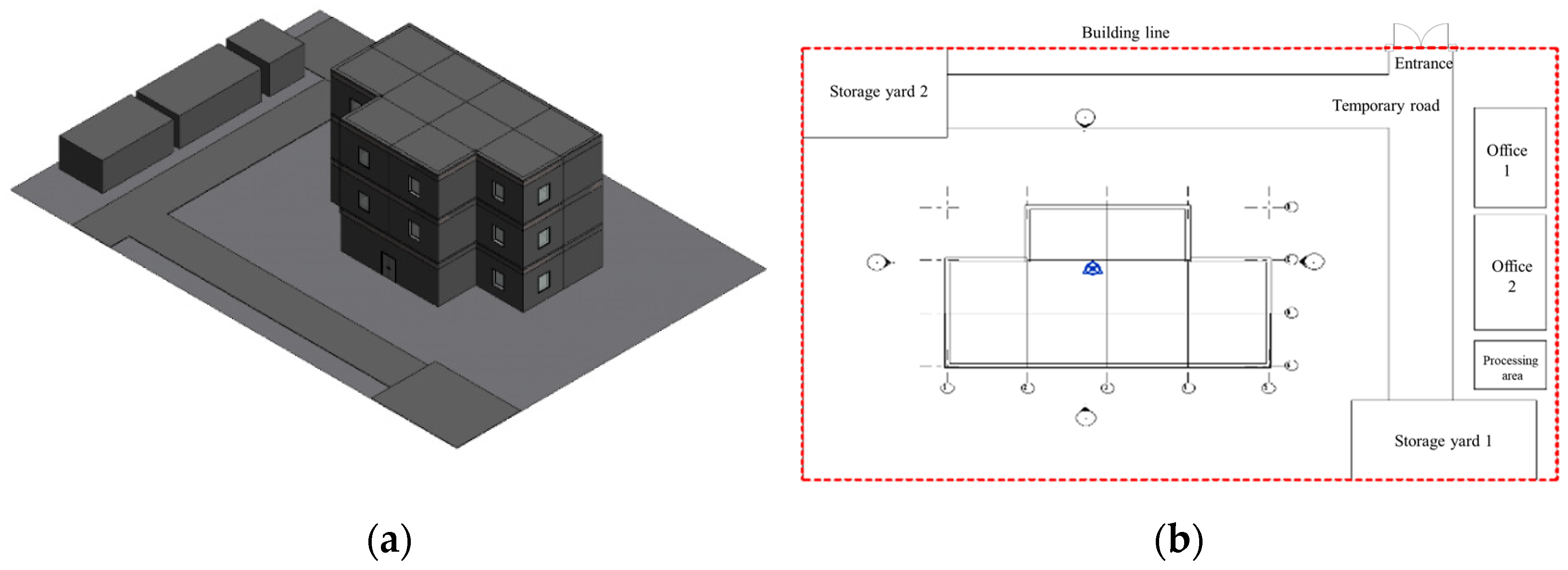
5. Case Study
5.1. Data Input
5.2. Initial Crane Type Selection
5.3. Constraint Checks
5.4. Optimal Combination of Feasible Location Points
6. Conclusions
Author Contributions
Funding
Institutional Review Board Statement
Informed Consent Statement
Data Availability Statement
Acknowledgments
Conflicts of Interest
References
- Kang, S.; Miranda, E. Planning and visualization for automated robotic crane erection processes in construction. Autom. Constr. 2006, 15, 398–414. [Google Scholar] [CrossRef]
- Lacey, A.; Chen, W.; Hao, H.; Bi, K. Structural response of modular buildings–An overview. J. Build. Eng. 2018, 16, 45–56. [Google Scholar] [CrossRef] [Green Version]
- Olearczyk, J.; Al-Hussein, M.; Bouferguene, A.; Telyas, A. 3D-Modeling for Crane Selection and Logistics for Modular Construction On-Site Assembly. In Computing in Civil Engineering; ASCE: Reston, VA, USA, 2012. [Google Scholar] [CrossRef]
- Olearczyk, J.; Al-Hussein, M.; Bouferguène, A. Evolution of the crane selection and on-site utilization process for modular construction multilifts. Autom. Constr. 2014, 43, 59–72. [Google Scholar] [CrossRef]
- Lei, Z.; Han, S.; Bouferguene, A.; Taghaddos, H.; Hermann, U.; Al-Hussein, M. Algorithm for Mobile Crane Walking Path Planning in Congested Industrial Plants. J. Constr. Eng. Manag. 2015, 141, 05014016. [Google Scholar] [CrossRef]
- Lin, Y.; Yu, H.; Sun, G.; Shi, P. Lift Path Planning without Prior Picking/Placing Configurations: Using Crane Location Regions. J. Comput. Civ. Eng. 2016, 30, 04014109. [Google Scholar] [CrossRef]
- Kang, S.; Miranda, E. Computational methods for coordinating multipole construction cranes. J. Comput. Civ. Eng. 2008, 22, 252–263. [Google Scholar] [CrossRef] [Green Version]
- Fang, Y.; Teizer, J. A Multi-User Virtual 3D Training Environment to Advance Collaboration Among Crane Operator and Ground Personnel in Blind Lifts. In Computing in Civil and Building Engineering; ASCE: Reston, VA, USA, 2014. [Google Scholar] [CrossRef] [Green Version]
- Chen, Y.-C.; Chi, H.-L.; Kang, S.-C.; Hsieh, S.-H. Attention-Based User Interface Design for a Tele-Operated Crane. J. Comput. Civ. Eng. 2016, 30, 04015030. [Google Scholar] [CrossRef]
- Al-Hussein, M.; Niaz, M.A.; Yu, H.; Kim, H. Integrating 3D visualization and simulation for tower crane operations on con-struction sites. Autom. Constr. 2006, 15, 554–562. [Google Scholar] [CrossRef]
- Mara, T.G. Effects of a Construction Tower Crane on the Wind Loading of a High-Rise Building. J. Struct. Eng. 2010, 136, 1453–1460. [Google Scholar] [CrossRef]
- Ali, G.M.; Kosa, J.; Bouferguene, A.; Al-Hussein, M. Competitive Assessment of Ice and Frozen Silt Mat for Crane Ground Support Using Finite-Element Analysis. J. Constr. Eng. Manag. 2021, 147, 04021038. [Google Scholar] [CrossRef]
- Ali, G.M.; Olearczyk, J.; Bouferguene, A.; Al-Hussein, M. Implementation of Combined Loading to Calculate Ground Bearing Pressure under Crawler Crane Tracks. J. Constr. Eng. Manag. 2021, 147, 04021051. [Google Scholar] [CrossRef]
- Yu, G.Y.H. Forensic investigation on crane accidents. Int. J. Forensic Eng. 2017, 3, 319–341. [Google Scholar] [CrossRef]
- Wang, R.D.; Zayed, T.; Pan, W.; Zheng, S.; Tariq, S. A system boundary-based critical review on crane selection in building construction. Autom. Constr. 2020, 123, 103520. [Google Scholar] [CrossRef]
- Al-Hussein, M.; Alkass, S.; Moselhi, O. An algorithm for mobile crane selection and location on construction sites. Constr. Innov. 2001, 1, 91–105. [Google Scholar] [CrossRef]
- Moselhi, O.; Alkass, S.; Al-Hussein, M. Innovative 3D-modelling for selecting and locating mobile cranes. Eng. Constr. Arch. Manag. 2004, 11, 373–380. [Google Scholar] [CrossRef]
- Al-Hussein, M.; Alkass, S.; Moselhi, O. Optimization Algorithm for Selection and on Site Location of Mobile Cranes. J. Constr. Eng. Manag. 2005, 131, 579–590. [Google Scholar] [CrossRef]
- Wu, D.; Lin, Y.; Wang, X.; Wang, X.; Gao, S. Algorithm of Crane Selection for Heavy Lifts. J. Comput. Civ. Eng. 2011, 25, 57–65. [Google Scholar] [CrossRef]
- Hasan, S.; Al-Hussein, M.; Hermann, U.H.; Safouhi, H. Interactive and Dynamic Integrated Module for Mobile Cranes Supporting System Design. J. Constr. Eng. Manag. 2010, 136, 179–186. [Google Scholar] [CrossRef]
- Han, S.H.; Hasan, S.; Bouferguène, A.; Al-Hussein, M.; Kosa, J. Utilization of 3D Visualization of Mobile Crane Operations for Modular Construction On-Site Assembly. J. Manag. Eng. 2015, 31, 04014080. [Google Scholar] [CrossRef]
- Han, S.; Al-Hussein, M.; Hasan, S.; Gökçe, K.U.; Bouferguene, A. Simulation of mobile crane operations in 3D space. In Proceedings of the 2012 Winter Simulation Conference, Berlin, Germany, 9–12 December 2012. [Google Scholar]
- Furusaka, S.; Gray, C. A model for the selection of the optimum crane for construction sites. Constr. Manag. Econ. 1984, 2, 157–176. [Google Scholar] [CrossRef]
- Han, S.; Bouferguene, A.; Al-Hussein, M.; Hermann, U. 3D-based crane evaluation system for mobile crane operation selection on mod-ular-based heavy construction sites. J. Constr. Eng. Manag. 2017, 143, 04017060. [Google Scholar] [CrossRef]
- Zaki, T.M.; Hosny, O.; Nassar, K. An automated model for selecting the optimum mobile crane model and on-site position using genetic algorithms. In Proceedings of the Canadian Society for Civil Engineering’s 5th International/11th Construction Specialty Conference, Vancouver, BC, Canada, 8–10 June 2015; p. 128. [Google Scholar]
- Taghaddos, H.; AbouRizk, S.; Mohamed, Y.; Hermann, U. Simulation-Based Multiple Heavy Lift Planning in Industrial Construction. In Construction Research Congress; ASCE: Reston, VA, USA, 2010; pp. 349–358. [Google Scholar] [CrossRef]
- Raynar, K.A.; Smith, G.R. Intelligent Positioning of Mobile Cranes for Steel Erection. Comput. Civ. Infrastruct. Eng. 1993, 8, 67–74. [Google Scholar] [CrossRef]
- Tantisevi, K.; Akinci, B. Simulation-Based Identification of Possible Locations for Mobile Cranes on Construction Sites. J. Comput. Civ. Eng. 2008, 22, 21–30. [Google Scholar] [CrossRef]
- Lei, Z.; Taghaddos, H.; Olearczyk, J.; Al-Hussein, M.; Hermann, U. Automated Method for Checking Crane Paths for Heavy Lifts in Industrial Projects. J. Constr. Eng. Manag. 2013, 139, 04013011. [Google Scholar] [CrossRef]
- Ding, L.; Zhou, Y.; Akinci, B. Building Information Modeling (BIM) application framework: The process of expanding from 3D to computable nD. Autom. Constr. 2014, 46, 82–93. [Google Scholar] [CrossRef]
- Hermann, U.; Hendi, A.; Olearczyk, J.; Al-Hussein, M. An Integrated System to Select, Position, and Simulate Mobile Cranes for Complex Industrial Projects. In Proceedings of the Construction Research Congress 2010, Banff, AB, Canada, 8–10 May 2010; pp. 267–276. [Google Scholar]
- Han, S.; Lei, Z.; Bouferguene, A.; Al-Hussein, M.; Hermann, U. 3D Visualization-Based Motion Planning of Mobile Crane Operations in Heavy Industrial Projects. J. Comput. Civ. Eng. 2016, 30, 04014127. [Google Scholar] [CrossRef]
- Kang, S.; Miranda, E. Numerical methods to simulate and visualize detailed crane ctivities. Comput. Aided Civ. Infrastruct. Eng. 2009, 24, 169–185. [Google Scholar] [CrossRef]
- Tantisevi, K.; Akinci, B. Automated generation of workspace requirements of mobile crane operations to support conflict de-tection. Autom. Constr. 2007, 16, 262–276. [Google Scholar] [CrossRef]
- Wang, X.; Liu, J.; Liu, F.; Gao, S. Collision-free locating of mobile cranes in 3D lifting system. In Proceedings of the ASME 2010 International Design Engineering Technical Conferences and Computers and Information in Engineering Conference, Montreal, QC, Canada, 15–18 August 2010; pp. 479–486. [Google Scholar]
- Zi, B.; Lin, J.; Qian, S. Localization, obstacle avoidance planning and control of a cooperative cable parallel robot for multiple mobile cranes. Robot. Comput. Manuf. 2015, 34, 105–123. [Google Scholar] [CrossRef]
- Ji, Y.; Leite, F. Optimized planning approach for multiple tower cranes and material supply points using mixed-integer pro-gramming. J. Constr. Eng. Manag. 2020, 146, 04020007. [Google Scholar] [CrossRef]
- Briskorn, D.; Dienstknecht, M. Mixed-integer programming models for tower crane selection and positioning with respect to mutual interference. Eur. J. Oper. Res. 2018, 273, 160–174. [Google Scholar] [CrossRef]
- Yeoh, J.K.W.; Chua, D.K.H. Optimizing Crane Selection and Location for Multistage Construction Using a Four-Dimensional Set Cover Approach. J. Constr. Eng. Manag. 2017, 143, 04017029. [Google Scholar] [CrossRef]
- Lin, J.; Fu, Y.; Li, R.; Lai, W. An Algorithm for Optimizing the Location and Type Selection of Attached Tower Cranes Based on Value Engineering. In ICCREM 2020: Intelligent Construction and Sustainable Buildings; ASCE: Reston, VA, USA, 2020; pp. 106–117. [Google Scholar] [CrossRef]
- Yoon, S.; Park, M.; Jung, M.; Hyun, H.; Ahn, S. Multi-objective optimization model for tower crane layout planning in modular con-struction. Korean J. Constr. Eng. Manag. 2021, 22, 36–46. [Google Scholar]
- Pan, Z.; Guo, H.; Li, Y. Automated Method for Optimizing Feasible Locations of Mobile Cranes Based on 3D Visualization. Procedia Eng. 2017, 196, 36–44. [Google Scholar] [CrossRef]
- Zhou, Y.; Guo, H.; Ma, L.; Zhang, Z.; Skitmore, M. Image-based onsite object recognition for automatic crane lifting tasks. Autom. Constr. 2020, 123, 103527. [Google Scholar] [CrossRef]
- Hongling, G.; Ying, Z.; Xiaotian, Y.; Zhubang, L.; Fan, X. Automated mapping from an IFC data model to a relational database model. J. Tsinghua Univ. 2021, 61, 152–160. [Google Scholar]
- Available online: https://cn.auto-che.com/b/puyuan/truck-crane.html (accessed on 22 March 2022).


| Type | Position (x, y, z), | Size | Others |
|---|---|---|---|
| Wall | Vertical: starting position Horizontal: wall center line, core layer center line, surface layer center line, surface layer internal/external line, core layer internal/external line | Length L, Depth D, Height H | ID, Floor number F, Height of floor HF, Volume V, Time T |
| Slab | Endpoint position | Depth D | ID, Floor number F, Height of floor HF, Volume V, Time T |
| Column | Column center point | Section size b*h, Height H | ID, Floor number F, Height of floor HF, Volume V, Time T |
| Beam | Vertical: starting position Horizontal: section center point | Section size b*h, Height H | ID, Floor number F, Height of floor HF, Volume V, Time T |
| Stairs | Endpoint position | - | ID, Floor number F, Height of floor HF, Volume V, Time T |
| Roof | Endpoint position | - | ID, Floor number F, Height of floor HF, Volume V, Time T |
| Constraint | Required Information | Whether Directly Obtainable from the Parsed BIM Model | Data Required from the BIM Model |
|---|---|---|---|
| Environmental constraint | Outside boundary of a building’s first floor | Needs conversion calculation | Coordinates and size of the first floor wall |
| Boundary of main road and temporary facilities | Obtained directly | - | |
| Operation constraint | Original and target positions of a lifting component | Needs conversion calculation | Relative position, size, direction, and height of the component |
| Weight of the component | Needs conversion calculation | Material and volume of the component | |
| Safety constraint | Height of the building, the outside boundary, and location of a crane jib | Needs conversion calculation | Time, coordinates of slab, wall and column, and location of crane |
| Constraints/ Optimization | Required Information |
|---|---|
| Environmental constraint | Outside boundary of a carne after the full extension of legs Rotation radius of the turntable |
| Operation constraint | Rated lifting weight corresponding to the length and radius of different boom |
| Minimum lifting time | Boom variation time Maximum elevation of boom Maximum speed of rotation |
| Lowest price of crane | Market price of crane |
| Working Radius (m) | Boom Length (m) | ||||||||
|---|---|---|---|---|---|---|---|---|---|
| 13.0 | 17.8 | 22.5 | 27.2 | 31.9 | 36.6 | 41.3 | 46.0 | 50.4 | |
| 3.0 | 100 | 80.0 | |||||||
| 3.5 | 93.0 | 77.0 | 62.0 | ||||||
| 4.0 | 88.0 | 72.0 | 62.0 | ||||||
| 4.5 | 79.0 | 67.0 | 61.0 | 42.0 | |||||
| 5.0 | 72.0 | 62.0 | 60.0 | 42.0 | 40.0 | ||||
| 5.5 | 65.0 | 58.0 | 56.0 | 42.0 | 39.0 | ||||
| 6.0 | 59.0 | 55.0 | 52.0 | 42.0 | 37.5 | 31.5 | |||
| 6.5 | 54.0 | 52.0 | 48.2 | 40.5 | 35.8 | 31.0 | |||
| 7.0 | 50.0 | 49.0 | 45.0 | 39.0 | 34.5 | 29.5 | |||
| 7.5 | 46.0 | 45.0 | 42.5 | 37.0 | 33.0 | 28.7 | |||
| 8.0 | 42.0 | 41.0 | 40.5 | 35.5 | 31.8 | 27.6 | 23.5 | ||
| 9.0 | 36.5 | 35.5 | 35.0 | 32.5 | 29.5 | 25.7 | 22.0 | 18.5 | |
| 10.0 | 32.0 | 31.0 | 30.5 | 30.0 | 27.5 | 24.0 | 20.8 | 17.5 | |
| 11.0 | 27.5 | 26.5 | 27.5 | 25.7 | 22.6 | 19.5 | 16.5 | 14.0 | |
| 12.0 | 23.5 | 23.3 | 24.5 | 24.0 | 21.2 | 18.9 | 15.9 | 13.2 | |
| 14.0 | 17.5 | 17.0 | 18.5 | 19.5 | 18.8 | 16.9 | 14.5 | 12.2 | |
| 16.0 | 13.0 | 14.2 | 15.0 | 16.0 | 15.2 | 13.2 | 11.2 | ||
| 18.0 | 10.0 | 11.2 | 12.0 | 12.6 | 13.2 | 12.0 | 10.2 | ||
| 20.0 | 9.0 | 9.7 | 10.3 | 10.9 | 11.0 | 9.3 | |||
| 22.0 | 7.2 | 7.9 | 8.5 | 9.0 | 9.4 | 8.7 | |||
| 24.0 | 6.2 | 7.0 | 7.6 | 7.9 | 8.0 | ||||
| 26.0 | 5.0 | 5.8 | 6.3 | 6.5 | 6.9 | ||||
| 28.0 | 4.9 | 5.2 | 5.6 | 5.8 | |||||
| 30.0 | 3.9 | 4.3 | 4.8 | 4.9 | |||||
| 32.0 | 3.0 | 3.6 | 3.9 | 4.2 | |||||
| 34.0 | 2.8 | 3.2 | 3.6 | ||||||
| 36.0 | 2.2 | 2.7 | 2.9 | ||||||
| 38.0 | 2.2 | 2.4 | |||||||
| 40.0 | 1.8 | 1.9 | |||||||
| 42.0 | 1.6 | ||||||||
| Crane Model | Maximum Lifting Capacity (T) | Maximum Boom Length (m) | Maximum Working Radius (m) | Cost (Yuan/per Machine) |
|---|---|---|---|---|
| QY16D | 16 | 30.5 | 22 | 1100 |
| QY20G | 20 | 32.27 | 28 | 1360 |
| QY25K-I | 25 | 33 | 30 | 1800 |
| QY50K-II | 50 | 42.7 | 32 | 2960 |
| QY65K | 65 | 42 | 30 | 3500 |
| QY70K | 70 | 44.5 | 36 | 4780 |
| QY80K | 80 | 45 | 36 | 5000 |
| QY90K | 90 | 55 | 50 | 5800 |
| QY100K-I | 100 | 51 | 42 | 6833 |
| QY130K | 130 | 58 | 56 | 6900 |
| QY160K | 160 | 62 | 52 | 7000 |
Publisher’s Note: MDPI stays neutral with regard to jurisdictional claims in published maps and institutional affiliations. |
© 2022 by the authors. Licensee MDPI, Basel, Switzerland. This article is an open access article distributed under the terms and conditions of the Creative Commons Attribution (CC BY) license (https://creativecommons.org/licenses/by/4.0/).
Share and Cite
Guo, H.; Zhou, Y.; Pan, Z.; Zhang, Z.; Yu, Y.; Li, Y. Automated Selection and Localization of Mobile Cranes in Construction Planning. Buildings 2022, 12, 580. https://doi.org/10.3390/buildings12050580
Guo H, Zhou Y, Pan Z, Zhang Z, Yu Y, Li Y. Automated Selection and Localization of Mobile Cranes in Construction Planning. Buildings. 2022; 12(5):580. https://doi.org/10.3390/buildings12050580
Chicago/Turabian StyleGuo, Hongling, Ying Zhou, Zaiyi Pan, Zhitian Zhang, Yantao Yu, and Yan Li. 2022. "Automated Selection and Localization of Mobile Cranes in Construction Planning" Buildings 12, no. 5: 580. https://doi.org/10.3390/buildings12050580
APA StyleGuo, H., Zhou, Y., Pan, Z., Zhang, Z., Yu, Y., & Li, Y. (2022). Automated Selection and Localization of Mobile Cranes in Construction Planning. Buildings, 12(5), 580. https://doi.org/10.3390/buildings12050580