Article

Application of BRB to Seismic Mitigation of Steel Truss Arch Bridge Subjected to Near-Fault Ground Motions

1
College of Civil Engineering, Tongji University, Shanghai 200092, China
2
College of Engineering, University of Auckland, Auckland 1023, New Zealand
3
Shenyang Geotechnical Investigation & Surveying Research Institute Co., Ltd., Shenyang 110004, China
4
College of Civil, Environmental and Land Magement Engineering, Polytechnic University of Milan, 20133 Milan, Italy
5
College of Transportation Science and Engineering, Harbin Institute of Technology, Harbin 150096, China
*
Author to whom correspondence should be addressed.
Buildings 2022, 12(12), 2147; https://doi.org/10.3390/buildings12122147
Submission received: 16 October 2022 / Revised: 23 November 2022 / Accepted: 1 December 2022 / Published: 6 December 2022
(This article belongs to the Special Issue New Trends in Seismic Performance Evaluation)

Abstract

:
In this paper, the seismic response of a steel truss arch bridge subjected to near-fault ground motions is studied. Then, the idea of applying buckling restrained braces (BRBs) to a steel truss arch bridge in near-fault areas is proposed and validated. Firstly, the basic characteristics of near-fault ground motions are identified and distinguished. Furthermore, the seismic response of a long span steel truss arch bridge in the near fault area is analyzed by elastic-plastic time analysis. Finally, the braces prone to buckling failure are replaced by BRBs to reduce the seismic response of the arch rib through their energy dissipation properties. Four BRB schemes were proposed with different yield strengths, but the same initial stiffness. The basic period of the structure remains the same. The results show that near-fault ground motion will not only obviously increase the displacement and internal force response of the bridge, but also cause more braces to buckle. By replacing a portion of the normal bars with BRBs, the internal forces and displacements of the arch ribs can be reduced to some extent, which is more prominent under the action of pulsed ground motion. There is a clear correlation between the damping effect and the parameters of BRB, so an optimized solution should be obtained by comparison and calculation.

Graphical Abstract

1. Introduction

In the event of an earthquake, the ground motions in the areas within 20 km of the fault have a super destructive power. In recent years, some historical earthquakes have broken out in some countries and regions, and some valuable ground motions have been recorded. These seismic data [1] provide conditions for structural engineers to carry out seismic research.
Seismologists and engineers have analyzed the characteristics of near fault ground motions in some ways. Somerville et al. [2] have pointed out that pulse effects in near-fault areas cause spatial variations in ground motion amplitude and duration. Their characteristics and mechanism have been elaborated by many studies (Wu et al. [3], Yang and Zhou [4], Yan and Chen [5]). Because of the difference of fault rupture mechanism, pulse-like ground motions can be divided into forward-directivity pulses (F-D pulses) and fling-step pulses (F-S pulses). The velocity time history of forward-directivity pulses usually contain double or multiple peaks. The ground motions with fling-step pulses usually exhibit two important characteristics: single velocity pulse and permanent ground displacement, which may make the structure subject to large deformations and internal forces. In terms of research methods, Chopra and Chintanapakdee [6] have extended well-known concepts of elastic and inelastic response spectra based on far-fault motion to near-fault motion. Mavroeidis and Papageorgiou [7] have proposed a simple analytical model for the representation of pulse-like ground motions, which adequately describes the impulsive character of near-fault ground motions both qualitatively and quantitatively. Ghahari et al. [8] have used the moving average filtering method with appropriate cut-off frequency to decompose the near-fault ground motion into two components with different frequency contents. This method has been promoted in recent years. On this basis, Li et al. [9] have proposed a recorded decomposition integration method to synthesize artificial pulse-like ground motion by combining high-frequency background records with simple equivalent pulses.
Thus, scientists and engineers now have a mature understanding of the mechanism, characteristics, and research methods of near-fault earthquakes, but their impact on structures needs more attention. Some researchers (Billah et al. [10], Davoodi et al. [11], Cui and Sheng [12], Losanno et al. [13]) have studied the seismic responses of various structures, including frames, dams, underground structures, and bridges near faults. Some researchers have tried to find correlations between ground motion parameters and structural responses but there have been no consistent consensus (Chen et al. [14]). The response spectrum is an important way to investigate the special influence of near-fault ground motion on structures. Yang and Zhao [15] have studied the influence of near-fault ground motions with forward-directivity pulse and fling-step pulse on the seismic performance of base-isolated buildings with lead rubber bearings. Through time history and damage analyses of a tested 3-storey reinforced concrete frame under 204 near-fault pulse-type records, some researchers (Vui Van et al. [16], Zaker et al. [17], Upadhyay et al. [18]) found that velocity spectrum intensity is leading parameter demonstrating the best correlation.
In addition to the above studies, the low-frequency pulse effects of near-fault seismic waves lead to the need for more attention to their effects on long-period structures. Adanur et al. [19] have compared the effects of near-fault and far-fault ground motions on the geometrically non-linear seismic behavior of suspension bridges. Shrestha [20] presented an analytical investigation on the effect of the near fault ground motions on a long span cable-stayed bridge considering the vertical ground motion. They found that near-fault ground motions produce greater displacements and internal forces on suspension bridges and cable-stayed bridges compared to far-fault ground motions. However, fewer studies have been conducted on the seismic response of near-fault arch bridges. The arch bridge has a large span and high material utilization rate, which is especially suitable for solid rocks in mountainous and canyon areas near faults. So it is necessary to study the near fault seismic response of the arch bridge. Some researchers (Lu et al. [21], Bai et al. [22], Alvarez et al. [23], R. Li et al. [24], Bazaez et al. [25]) studied the seismic response of arch bridges by means of pushover analysis or time-history analysis, but have not fully considered the special destructiveness of near-fault ground motions to this flexible structure.
The seismic responses of the arch bridge in the near fault areas need further analysis, and the corresponding seismic mitigation methods are also worthy of attention. Chen et al. [26,27,28] have pointed out that advanced seismic isolation devices and systems have been recognized as promising measures toward resilient design of bridge structures. Some researchers (Alam et al. [29], Dezfuli and Alam [30], R. Li et al. [24]) have proposed seismic mitigation methods, such as rubber bearings, elastic-plastic steel dampers, and shape memory alloys, but these devices are limited and uneconomical in arch bridges. Kim and Choi [31] have pointed that buckling-restrained braces (BRBs) can yield in tension and compression, exhibit stable and predictable hysteretic behavior, provide significant energy dissipation capacity and ductility, and are an attractive alternative to conventional steel braces. Some researchers (Hoveidae and Rafezy [32], Li et al. [33], Xing et al. [34]) have optimized its structure and applied it to buildings, obtaining good seismic mitigation effect. Beiraghi and Zhou [35] have designed a braced frame consisting of steel buckling-restrained braces (BRB model), braces with shape memory alloy (SMA model), or combination of BRB and SMA braces. It is worth mentioning that they have taken advantage of performance-based design concepts. Concentric braced frames have been combined with moment-resisting frame as a dual system subjected to near-field pulse-like and far-field ground motions (Wang et al. [36]). To date, BRBs have been used extensively in building structures, but are not as widely used or researched in bridge structures. Dong et al. [37] installed self-centering buckling-restrained braces on the reinforced concrete double-column bridge piers. Experimental results have demonstrated the obvious advantages of SC-BRB in increasing the strength and minimizing the residual deformation of the bridge column. Sosorburam and Yamaguchi [38] has conducted a parametric study on the seismic behavior of the truss bridge with BRB by changing the length, the cross-sectional area, the location, and the inclination. Xiang et al. [39] investigated the effect of BRB distribution on the seismic performance of retrofitted multi-story reinforced concrete high bridge piers. However, the application of BRB in a steel truss arch bridge is rare (Celik et al. [40]).
The objectives of this paper are to investigate special seismic response of long-period steel truss arch bridge and introduce BRBs into the vibration reduction in steel truss arch bridge in near fault areas. Firstly, nine ground motions with different characteristics are selected from PEER database [1], and their differences are analyzed by response spectrum. Subsequently, taking a steel truss arch bridge as the research object, the response law of the bridge under forward-directivity pulsed, fling-step pulsed, and non-pulsed motions is analyzed with an elastic-plastic time history analysis method. Finally, the seismic mitigation method of using BRB to replace buckling-prone components is proposed and verified. The results show that the internal force and displacement of the arch ribs can be reduced by replacing a portion of the normal bars with BRBs, which is more prominent under the action of pulsed ground motion.

2. Near-Fault Ground Motions

2.1. Selected Seismic Waves

The Chi-Chi earthquake in Taiwan in 1999 is a typical large earthquake near the fault. In this paper, nine ground motions of different types in this earthquake are taken from the latest database of the PEER NGA-West 2. The selection principles of ground motion are as follows: (1) the fault is within 20 km; and (2) peak acceleration and velocity are greater than 100 cm/s2 and 30 cm/s, respectively. The three groups of time-history of ground motion velocity with different characteristics are shown in Figure 1a–i. The first group contains three seismic waves, TCU-051, TCU-082, and TCU-102, representing F-D effect seismic waves; the second group contains three seismic waves, TCU-052, TCU-068, and TCU-075, representing F-S effect seismic waves; the third group contains three seismic waves, TCU-071, TCU-089, and TCU-079, representing non-pulse effect seismic waves. The basic properties of the ground motions, such as the closest distance to fault rupture (Rrup), peak ground acceleration (PGA), peak ground velocity (PGV), peak ground displacement (PGD), PGV/PGA, and pulse period (Tp) are listed in Table 1. PGV/PGA is usually taken as the pulse parameter in the study to preliminarily judge the strength of the velocity pulse. According to the preliminary judgment, the pulse effect of the selected P-S motions is the strongest, followed by the P-D motions. In contrast, the ordinary non pulse ground motion is gentle.

2.2. Response Spectrum of Seismic Waves

From the above-ground motion parameters, it can be seen that there are obvious differences in the motion characteristics of three different types of ground motion (Zaker at el. [41]). Therefore, further research is needed through response spectrum. The elastic response spectrum of linear elastic single-degree-of-freedom system with 5% damping ratio under three groups of ground motion is calculated, respectively, and the average value of each group is taken. The calculation results are shown in Figure 2a–c.
Comparing the response spectrum curves, the differences between the three types of ground motions are obvious. In the short period, the spectral velocity of non-pulse ground motion is the largest. In the middle period, the acceleration value of the ground motion with forward effect is the largest. In the long period, the acceleration value of ground motion with lightning effect is the largest. As for velocity spectrum and displacement spectrum, the spectrum value of pulse ground motion is larger than that of non-pulse ground motion in a long period. In general, the low-frequency components of pulse ground motion are relatively rich, which should be paid attention to in the design of long-period structures near faults.
The peak accelerations of the nine primary seismic waves are adjusted with reference to the Chinese seismic code for bridges (Wu at el. [3]). The rare earthquakes in the Chinese code are similar to ASCE maximum considered earthquakes. The studied bridge is in the octave zone, so the peak acceleration in rare earthquakes was adjusted to 400 cm/s2.

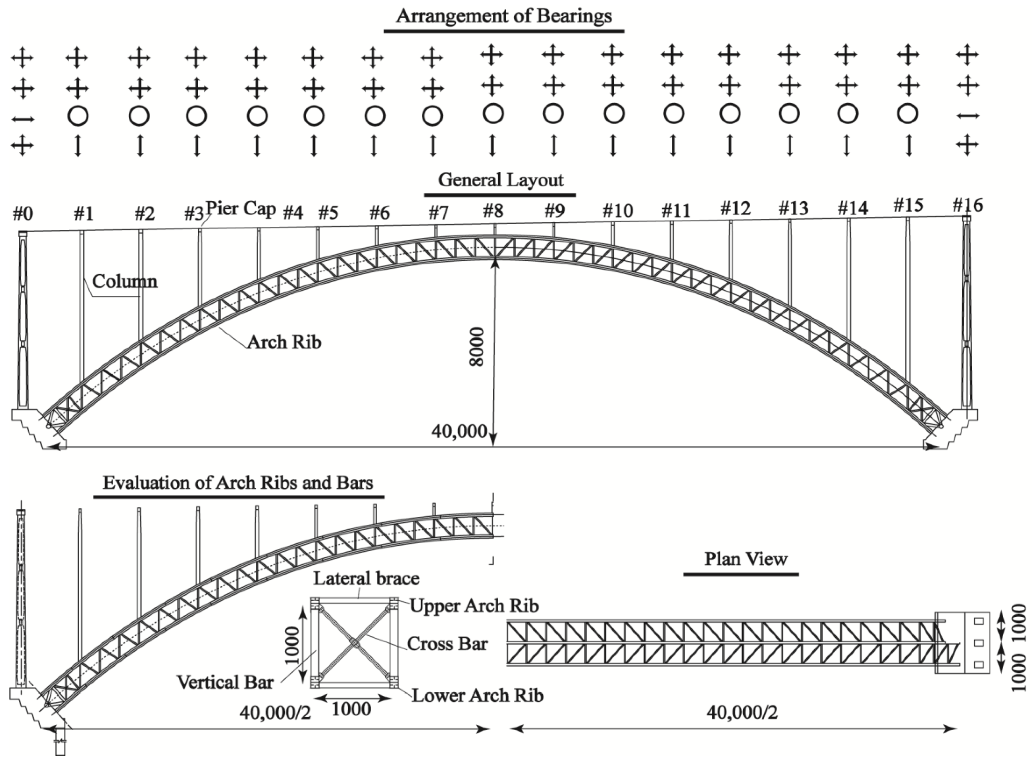
3. Bridge Prototype and Modelling

3.1. Case Study Bridge for System Response

The prototype bridge is a long-span steel truss arch bridge spanning a valley in a near-fault area. Its net span is 400 m, the vector span ratio is 1/5, and the arch axis is ducted. The main arch rib adopts steel truss structure, and the beam body is composed of steel and concrete. The height of the steel truss is 10 m, and the spacing of the three transverse arch ribs is 10 m. The arch rib adopts a steel box structure with equal section, with a height of 1.5 m and a width of 1.0 m. The columns on the arch ribs are steel-bending structures, and the three transverse columns are equal-section steel boxes. Stiffening ribs and transverse spacers are provided along the height of the columns. The columns are supported by steel bars in the transverse direction to improve stability and safety. The layout of the bridge is shown in Figure 3. Critical details and parameters are shown in Table 2. The brace members are made from Q345qD steel, with a nominal yield strength of 345 MPa. The elastic modulus, Poisson’s ratio, density of structural member are listed in Table 3.

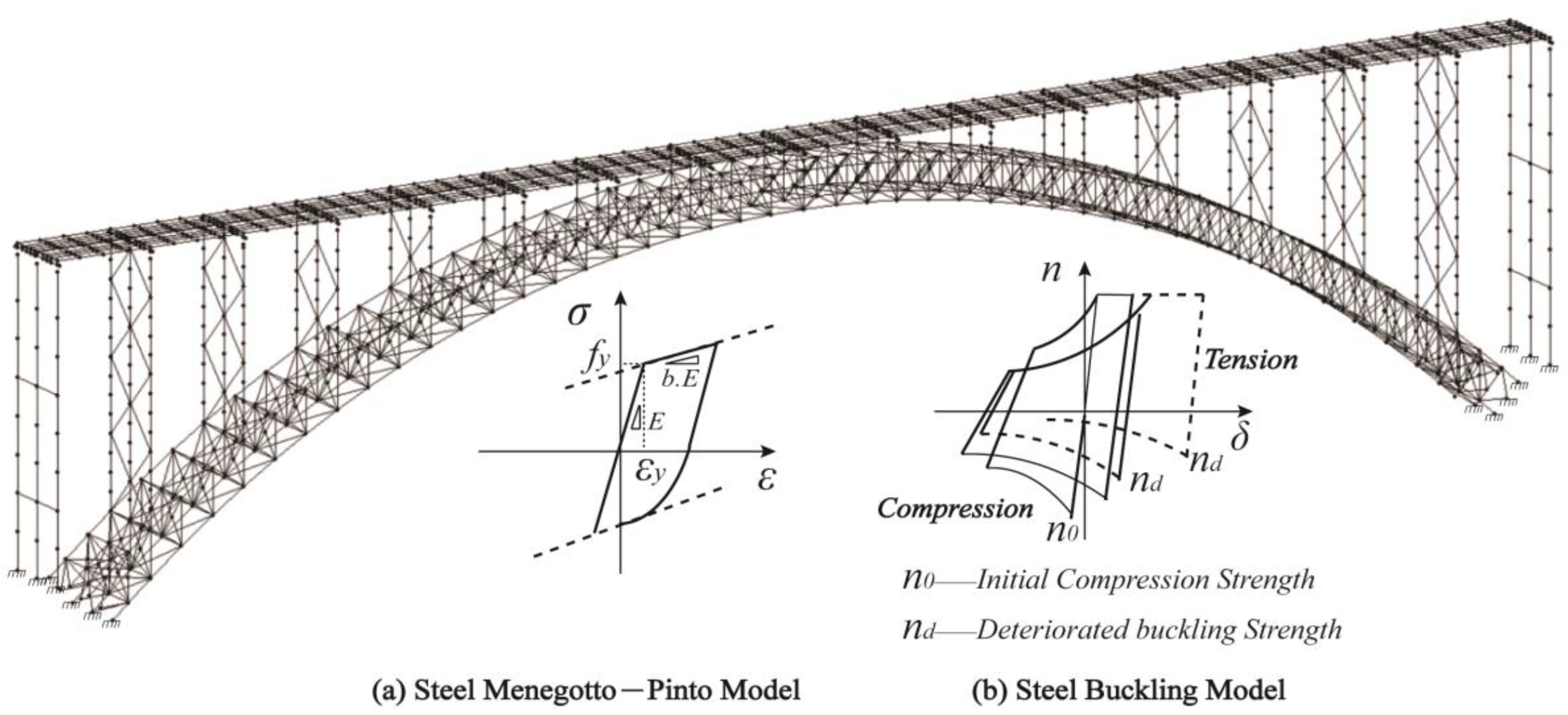
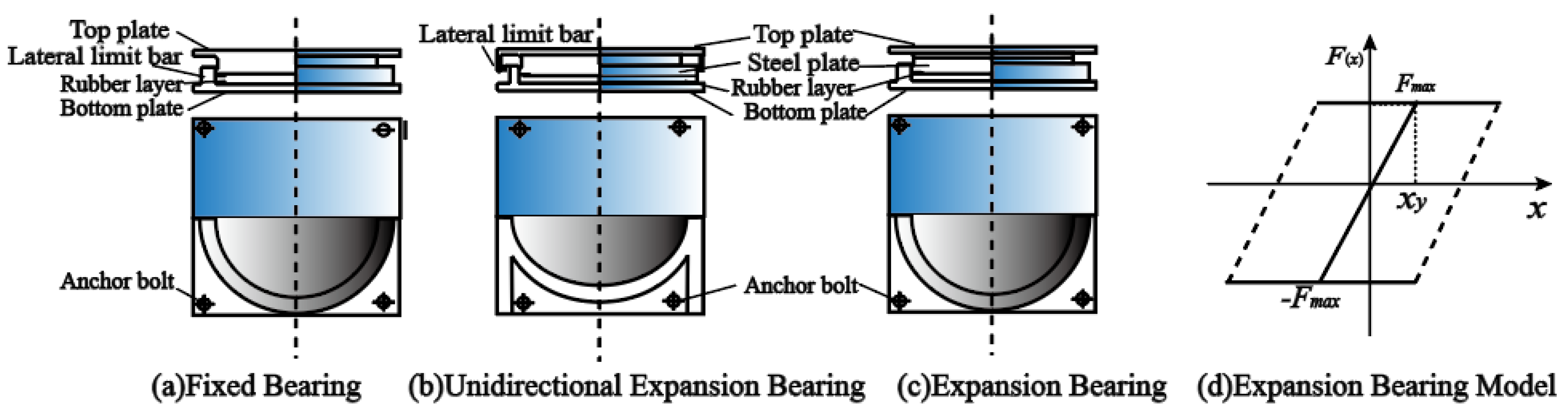
3.2. Finite Element Model

The finite element model of the bridge is established by means of the finite element software Midas Civil, as shown in Figure 4. The quality, stiffness, and boundary conditions directly determine the accuracy of the finite element analysis results. The arch ribs are simulated by the beam element, and the material model is a Menegotto–Pinto theoretical model (Carreño at el. [42]). To account for non-linearity, lateral braces, vertical bars, cross bars, and braces of columns are embodied by the elasto-plastic hinge element, and the material is simulated by a steel buckling model. The superstructure of the bridge was assumed to be elastic and was modeled by an elastic beam-column element with a modulus of elasticity of 3.45 × 10⁴ Mpa. A non-linear beam-column fiber element was adopted to model the non-linear behavior of the columns. The Concrete01 material model, which was developed based on the uniaxial Kent–Scott–Park model, was used for the concrete of the columns, with compressive strengths of 26.8 and 32.8 MPa for the unconfined and confined concrete, respectively. The reinforcing steel was modeled with uniaxial bilinear steel material of Steel01. The yield strength, elastic modulus and strain-hardening ratio were assumed to be 400 MPa, 200 GPa and 0.02, respectively.
In terms of boundary conditions, the support between the cover beam and the main beam is simulated with fixed support. At the end of the beam, movable supports are used to simulate the longitudinal constraints of the bridge. The bearing is a basin type rubber bearing, whose construction and model are drawn in Figure 5. The fixed direction of the bearing is restricted and the movable direction is represented by the bilinear model in Figure 5. The sliding displacement xy is 2 mm.

4. Bridge Response

The analysis of the dynamic characteristics shows that the first three order periods of the bridge are 1.651 s, 0.921 s, and 0.745 s in the longitudinal direction; 3.927 s, 1.612 s, and 0.809 s in the transverse direction; and 0.973 s, 0.741 s, and 0.577 s in the vertical direction. Elastoplastic time history analysis is used to simulate the seismic response of bridges under rare earthquakes. Assume that the bridge is perpendicular to the fault. The seismic waves with the same name are input in the longitudinal, lateral, and vertical directions of the bridge. The difference is that the PGA of the horizontal seismic wave is 400 cm/s2, while the vertical one is 2/3 of the horizontal one, which is determined by referring to the Chinese code [43]. In Figure 6, the results for the nine working conditions are listed and each seismic wave represents one working condition. The three conditions, TCU-051, TCU-082, and TCU-102, represent the bridge response under the F-D effect seismic waves, TCU-052, TCU-068, and TCU-075 represent the bridge response under the F-S effect seismic waves, and TCU-071, TCU-089, and TCU-079 represent the bridge response under the non-pulsed effect seismic waves. According to the internal force and displacement of key parts, such as arch foot, arch bottom, and 1/4 arch section, and the buckling of lateral braces, vertical bars, cross bars and braces of columns, the response law of the bridge is summarized.

4.1. Response of Arch Ribs

Under the action of three different types of ground motions, the envelope results of the internal force response of the arch ribs are shown in Figure 6a–c. The arch bridge span is 400 m, the horizontal coordinates of the graph are the positions of the arch ribs in the axial direction of the bridge and the vertical coordinates are the results of the various seismic responses. Figure 6 shows the envelope results for the axial forces of the arch ribs at each section. Figure 6b shows the results for in-plane bending moments and Figure 6c shows the results for out-of-plane bending moments. Under various cases, the maximum axial force of the arch rib occurs in the arch foot section, and the bending moment of the arch foot section is also much greater than that of the arch top and 1/4 arch section. The in-plane bending moment envelopment diagram is not smooth and appears zigzag fluctuation, which is mainly caused by the force change of the upper column directly connected to the arch ribs.
Compared with non-pulsed ground motions, the internal force of key sections of arch rib is obviously greater under pulsed ground motion. For example, the mean value of peak axial force of the arch foot under the action of three non-pulsed ground motions is 55,150.9 kN. The mean value under the action of F-D pulsed ground motions is 104,641.9 kN, and that under the action of F-S pulsed ground motions is 94,825.7 kN, which are increased by 89.7% and 71.9%, respectively, compared with the non-pulsed effect. For arch ribs at different positions, the influence of pulse effect is also different. The pulsed ground motion has the greatest influence on the peak moment of arch foot surface. Compared with non-pulsed ground motion, the increase rates of F-D effect and F-S effect pulse are 207% and 141.2%, respectively. Pulsed ground motions have the least influence on the axial force of the vault, and the increase rates of forward-direction pulse and fling-step pulse are only 10.5% and 7.6%, respectively.
In terms of deformation, the distribution of longitudinal and vertical deformation is similar. Figure 6d–f show the results of the displacement envelope of the arch rib section relative to the ground in the longitudinal, transverse, and vertical directions, respectively. The maximum displacement occurs near 1/4 arch section, while the peak value of lateral displacement occurs near the vault. The displacement responses in all directions under the two kinds of pulsed ground motions are much greater than those of non-pulsed ground motions. On the one hand, it is because that the time-domain energy of pulse type ground motion is concentrated and the low-frequency pulse component is rich, which makes it easier to excite the basic mode of arch bridge with long-period. On the other hand, compared with the ordinary ground motions, the internal force response of the component increases because of the huge velocity pulse. Thus, the braces near the arch foot are more prone to buckling failure, which reduces the overall stiffness of the structure, and then leads to the increase in displacements.
The influence of the P-S effect on displacement is greater than the F-D effect. The slip effect seismic wave chosen for the study has a larger impulse period than that of the directional effect seismic wave and is closer to the fundamental period of the steel truss arch bridge. Therefore, the displacement response is greater.
In general, long-period steel arch bridges are more susceptible to the low-frequency impulsive component of near-fault ground vibrations. Therefore, the seismic response of steel truss arch bridges under impulsive seismic action is much larger than that of non-impulsive ones.

4.2. Buckling of Braces

Under the action of rare ground motion, the various supports of the bridge will buckle to varying degrees. The number of buckling braces under pulse ground motion is much higher than that under non-pulse ground motion, as shown in Table 4.
Due to complex forces near the arch foot, the number and degree of buckling of all kinds of braces near the arch foot are the largest in each working condition. A small part of lateral braces near the 1/4 arch and the arch roof also suffer from buckling failure. Under the two kinds of pulsed ground motions, the braces buckle in different degrees, but it keeps elastic under three non-pulsed ground motions. Figure 7a–i show the state of the bridge braces under the action of nine seismic waves. Braces in green represent no buckling damage and braces in red represent buckling damage. In general, the number of buckling braces is proportional to the transverse displacement of the arch rib. The greater the lateral displacement is, the more likely the braces are to buckle, which will further weaken the lateral stiffness of the bridge.
Compared with vertical bars, the number and degree of buckling of lateral braces and cross bars are greater. When it comes to reasons, one is that the transverse stiffness of the bridge is obviously less than that of the longitudinal and vertical directions, which makes the forces of the transverse connecting members more unfavorable. The other is that the design strength of the transverse and cross bar members is smaller than that of the vertical bars. Therefore, it is necessary to focus on the transverse seismic response and seismic mitigation measures of large span steel truss arch bridges.
In summary, the axial force, bending moment and displacement response in all three directions of the arch ribs are significantly greater under pulsed seismic waves compared to non-pulsed seismic waves. From the perspective of the braces, more buckling damage occurs in the braces under the action of pulsed seismic waves.

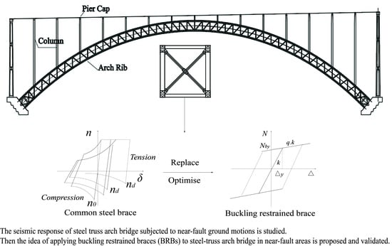
5. Seismic Mitigation Scheme Using BRB

The above research indicates that the transverse stiffness of steel truss arch bridge is insufficient, which makes it easy to be damaged by the pulse components of pulse-like ground motions. However, it is neither economical nor reasonable to increase the transverse stiffness singly during the design. Therefore, this paper attempts to introduce the buckling restrained braces (BRBs) into the seismic mitigation of arch bridge. Some braces are designed as BRBs to improve the overall mechanical performance of the bridge during earthquakes. It is expected that the BRBs can play the role of “fuse” to provide normal bearing capacity in the normal service condition and help the main structure maintain elasticity under frequent earthquake. Under the action of rare earthquakes with impulse effect, it yields earlier, but does not fail in buckling and still has considerable stiffness in hysteresis. It can not only prevent the collapse of the overall load carrying capacity of the bridge caused by buckling damage, but also protect the arch ribs by allowing the braces to fully dissipate the seismic energy under earthquakes.

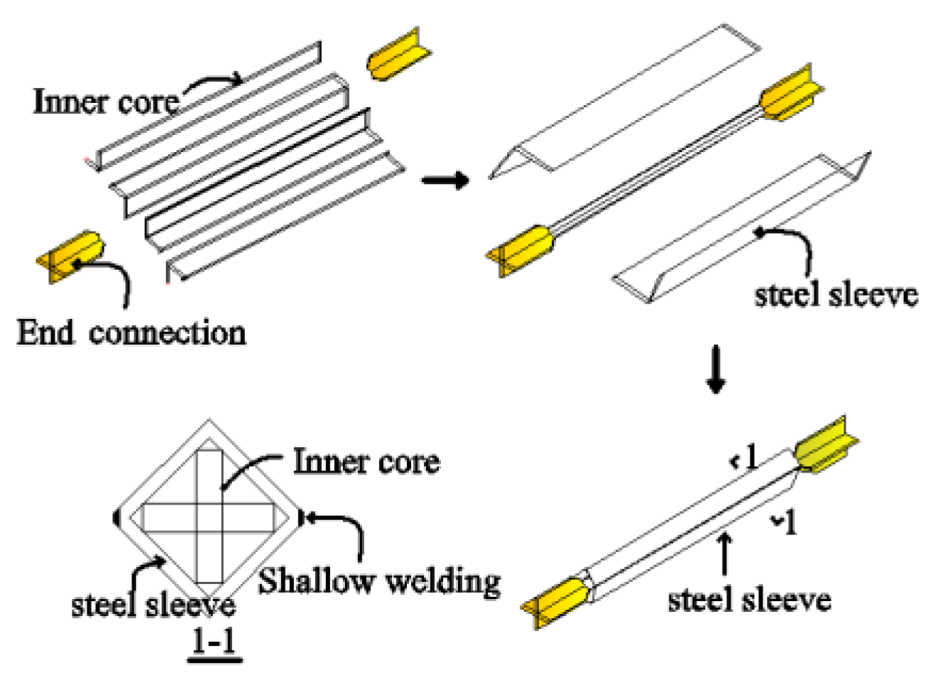
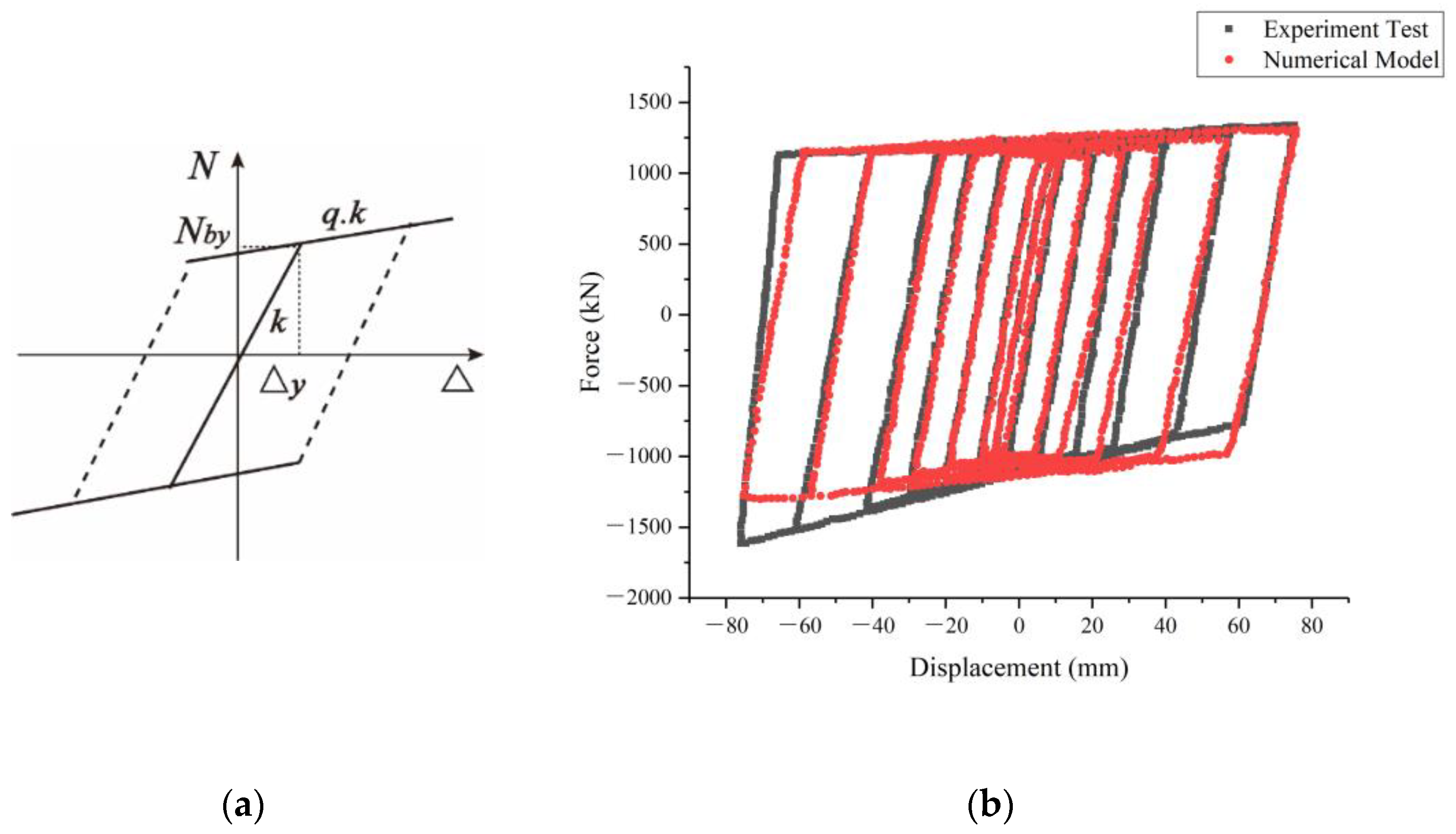
5.1. Design Parameters of BRB

When determining the design parameters, it needs to be considered that BRBs must keep elastic under frequent earthquake but can yield and consume energy under rare earthquake. Firstly, considering the condition of frequent earthquakes, the PGA of 9 seismic records is adjusted to 0.1 g. Then, the non-linear time history analysis is carried out. The maximum axial force of braces under various ground motions is shown in Table 5, and the calculation results are used as the main basis for preliminary design. After the deployment of BRBs, the bridge members and overall load capacity should not differ much from that of the prototype bridge.
Based on the seismic response data of the bridge, BRBs design and calculation are carried out with reference to technical specification for buckling restrained braces (DBJ/CT105-2011) [44]. In this paper, the structure of TJI (F.F. Sun at el. [45]) steel buckling restrained brace developed by Tongji University is adopted. TJI buckling restrained brace is made of steel, and the restrained sleeve is made of square steel tube. The restraint effect of outer sleeve on the yield section of core plate is realized by special stiffener. Physical object is shown in Figure 8, and main components are shown in Figure 9.
The calculation of BRBs is similar to that of ordinary brace, the difference is that the designer only need to check whether the strength meets the requirements without considering the instability. Considering that the stiffness of the brace joint is generally greater than that of the brace itself, the equivalent sectional area (Ae) of the brace in the model is larger than that of the brace itself (Abe).
The braces of the bridge are over 12 m. According to the design manual for supporting design with the length over 12 m, the yield section area of core plate is A1 = 0.99 Ae. Therefore, considering the steel area and yield strength of the core plate, the approximate formula for calculating the maximum design bearing capacity is obtained as Equation (1):
N b 1 = 0.9 f y A 1 = 0.9 f y 0.99 A b e 0.891 f y A e
Considering frequent earthquake load combination, the design value of maximum tension and compression axial force of BRBs should meet the requirements of Equation (2):
N N b 1 / γ r e 1.188 f y A e
where N represents design value of BRBs axial force, Nb1 represents design bearing capacity of BRBs, γre represents seismic adjustment coefficient, generally 0.75 according to Technical specification for buckling restrained braces (DBJ/CT105-2011).
Through the above methods, the specifications and dimensions of BRBs can be preliminarily obtained. Next, the yield bearing capacity of the model is calculated by Equation (3) as the basis of finite element analysis.
N b y = η y f y A 1
where Nby represents yield bearing capacity of BRBs, ηy represents super strength coefficient of core plate steel.
According to the above formulas, four different seismic mitigation schemes are formulated with the cross section area of the core panel as the variable. The dimensions and mechanical parameters of buckling restrained braces under the four schemes are preliminarily formulated, and the yield bearing capacity is calculated as shown in Table 6. The difference of each scheme is that the cross-sectional area of the selected core, so the design bearing capacity and yield bearing capacity are different, but the number and layout position are consistent.
The buckling-restrained braces are simulated by means of plastic hinge elements according to Technical specification for buckling restrained braces (DBJ/CT105-2011) [44]. The bi-linear model with equal tension and compression can be used in the elastic-plastic analysis of BRBs, as shown in Figure 10a, where Nby represents yield bearing capacity of BRBs, Δy represents initial plastic deformation, k represents elastic stiffness, and q represents strengthening coefficient of core steel plate.
The scaled uniaxial quasi-static reciprocating testing is commonly used to test the tensile and compressive properties of BRBs. The numerical model was subjected to a BRB quasi-static cyclic test and the results were compared with data extracted from published experimental as shown in Figure 10b [18]. The BRB numerical model shows stable hysteretic behavior, sufficient energy-dissipating capacity, and appropriate level of yield force, which matched the published experiment data well.

5.2. Layout Scheme of BRBs

The layout of buckling restrained braces should be able to give full play to its energy dissipation performance and meet the needs of the overall static bearing capacity and stability of the structure. According to the characteristics of steel truss arch bridge, the BRBs are arranged according to the following principles:
(1)
BRBs need to be arranged near sections with large force and relative displacement;
(2)
The layout of supports includes single diagonal bracing, V-shaped or herringbone form, but they should not be arranged in X-shaped cross form;
(3)
BRBs should be arranged in multiple directions of the structure, and it is expected to play a seismic mitigation role in multiple directions;
(4)
In order to reflect the seismic mitigation ratio of BRBs through comparative analysis, the study only replaces the original bridge braces with BRB members, without changing the number of braces;
(5)
The bearing capacity and dynamic characteristics of the bridge installed with BRB cannot be significantly changed.
Based on the above layout principles, a preliminary layout plan is drawn up, as shown in Figure 11a–d. There are 80 lateral braces, 50 Vertical bars, 50 Cross bars, and 8 column diagonal braces near the positions with large internal force and displacement designed as BRB members. The blue braces are the ordinary steel members, and the yellow braces are the BRBs. Table 7 lists the number of BRBs at different locations.

5.3. The Seismic Mitigation Effect of BRBs on Bridges near Faults

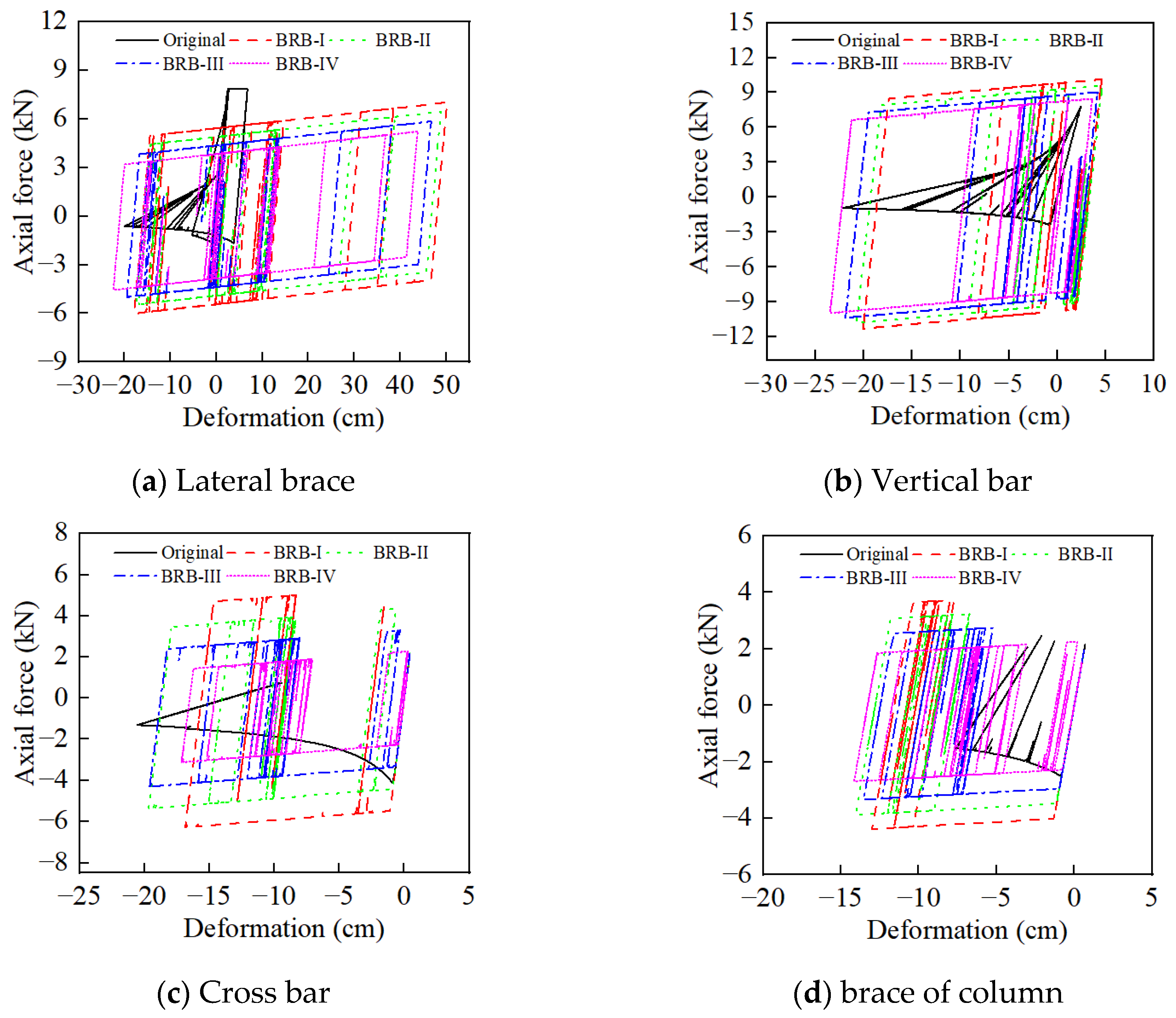
5.3.1. Comparison of Hysteresis Curves

The study solution developed was to use BRBs to replace the original braces, without changing the number of braces. There are four BRBs in total and their stiffness is the same as that of the normal steel bars in the original scheme, the difference being the difference in yield strength. So the basic period of the stiffness and elastic phase of the structure is the same as that for the prototype bridge. In an earthquake, the BRBs can yield but not buckle. This ensures that the stiffness and load-bearing capacity of the bars are not lost instantaneously, thus protecting the main structure.
The comparison of the hysteretic curves of the braces in each scheme is plotted in Figure 12a–d. It can be seen from the brace hysteretic curves that the lateral braces, cross bars, and braces of column are mainly subjected to compression in earthquake. The ordinary steel braces can keep elastic when they are under tension. However, when the axial pressure reaches about 0.5 times of the yield axial pressure, the stiffness loss is serious, and the hysteretic curve presents pinch effect, indicating that their energy dissipation capacity is poor. In contrast, BRBs can yield under both tension and compression, and the unloading stiffness is guaranteed without instantaneous loss. It has a large deformation capacity and plump hysteretic curve, which indicates that it has strong energy dissipation capacity. It is worth mentioning that because the pulsed ground motions are particularly unfavorable to the transverse stress of steel truss arch bridge, the deformation degree of lateral braces is greater than that of other braces, which should be paid attention to during designing.

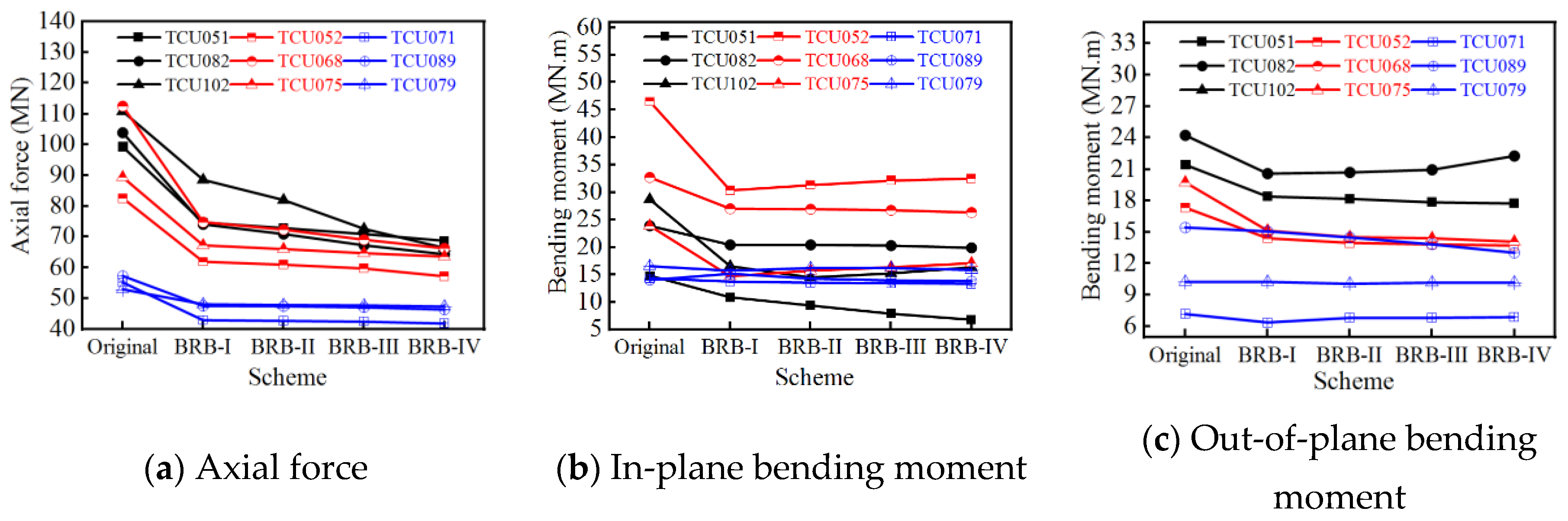
5.3.2. Effect of BRBs on Force and Displacement of Bridge

The comparison results of the internal force and displacement responses of the main sections of the original structure and the BRB seismic mitigation structure under three groups of ground motions are shown in Figure 13a–f.
The substitution of BRBs for ordinary steel braces can effectively reduce the axial force, in-plane bending moment, and transverse displacement of the arch rib. The seismic mitigation effect of BRBs varies with different types of ground motions. Seismic mitigation rate of the bridge under the action of pulse-like ground motions is much larger than that of the ordinary non-pulsed ground motions. Under the effect of impulse-free ground vibration, most of the bridge rods do not buckle, so the bridge bearing capacity is not significantly weakened, so the advantages of the seismic reduction scheme are not fully reflected.
The average reduction rate of the axial force of the arch foot in the BRB-I scheme is 22.7% for the F-D wave, 28.4% for the F-S wave, and only 16.3% for the non-pulse wave. The axial force envelope that should receive the most attention in an arch bridge is shown in Figure 14. Since the vertical seismic waves exacerbate the bending moment of the arch ribs and the damage of the bars, the BRB scheme also has a significant reduction in the internal bending moment in addition to the axial force of the arch ribs. For the in-plane bending moment, the reduction rates of these three groups are 28.2%, 26.3%, and 10.7%, respectively.
In comparison, the reduction rate of displacements in three directions is relatively small. The BRB seismic mitigation scheme has better effect on reducing lateral deformation than the longitudinal and vertical ones. The main reason is that the transverse displacement of the bridge is the most significant, and BRBs is essentially a displacement-based metal damper. In addition, more lateral braces and cross bar members that provide transverse support are replaced by BRBs, so that the transverse seismic mitigation rate is higher than the longitudinal and vertical of the bridge.
With the change of seismic mitigation scheme from I to IV, the yield strength of four BRBs braces decreases gradually, and the seismic mitigation rate of arch rib axial force increases gradually. However, with this change, the stiffness of the bridge decreases slightly. So in some conditions, the seismic mitigation effect of bending moment and lateral displacement is reduced. Thus, it can be seen that although the reduction in BRBs stiffness can continuously reduce the axial force of arch rib, it will weaken the seismic mitigation effect of bending moment and lateral displacement. Therefore, balance should be achieved through comparison in engineering, and then the optimal scheme should be selected.
For a more visual system of the above law, TCU-082 (F-D wave), TCU068 (F-S wave), and TCU079 (Non pulse wave) are selected in Figure 15 to show the time course results of the axial force of the arch foot and the lateral displacement of the arch top.
The yield strength of BRBs affects the seismic mitigation effect of lateral displacement. The transverse displacement seismic mitigation ratio of the bridge is relatively large. The time-history curve is plotted in Figure 15. Only the results for the first 40 s are shown in the figure. For both impulsive seismic waves, the BRB scheme reduces the response for most of the time, more prominently at the peak. Additionally, the rate of force reduction is more prominent than the displacement. For the non-pulsed seismic waves, little change is seen from the time course curves.
It is worth noting that for the displacement timescale of the TCU068 wave transverse, the peak displacement of the BRB-IV scheme is 20.3% larger than that of the BRB-III scheme at 15.32 s. At the same time, the reduction rate of other BRB schemes for forces fluctuates no more than 6.3% compared to the BRB-I scheme. Therefore, although properly weakening the stiffness of BRBs can reduce the seismic response of internal force of the bridge, it will be unfavorable to the displacement response if the stiffness of BRBs is too small. On the basis of ensuring the elastic and ultimate stability of the structure under small earthquakes, the designer should appropriately reduce the yield strength of BRBs near the section with small displacement and increase the yield strength near the section with large displacement. In this way, the area of hysteretic loop can be increased, which is beneficial to improve the overall seismic mitigation efficiency of the structure.
In addition to the areas of concern listed above, the results of the envelope of arch rib axial forces and in-plane bending moments are calculated in order to visualize the force variations of all arch ribs in the BRB scheme. Taking TCU102 as an example, Figure 16a,b shows the arch rib axial force envelope results of the original and BRB seismic mitigation structure. BRB seismic mitigation structure has the highest seismic mitigation rate for axial force near the arch foot, but the seismic mitigation efficiency is lower at top section of the arch, which should be paid enough attention to during research and design.
In summary, the substitution of BRBs for ordinary steel braces can effectively reduce the axial force, in-plane bending moment. However, the effect in terms of reducing displacement is very limited. Compared to non-pulsed seismic waves, BRBs are more effective in seismic mitigation under pulsed seismic waves, due to the fact that BRBs are more likely to yield and dissipate energy under the action of pulsed waves, which act to their full potential.

6. Conclusions

In this paper, nine ground motions are selected and divided into three groups according to their types, then the characteristics of near-fault ground motions are studied. Taking a steel truss arch bridge as the research object, the responses law of the bridge under pulsed ground motions are analyzed with the help of elastic-plastic time history analysis method. Finally, the buckling restrained braces are introduced into the seismic design of an arch bridge. The seismic mitigation effect is verified by elastic-plastic time history analysis. The main conclusions are as follows:
(1)
The low-frequency component of the pulsed ground motion in the near-fault zone significantly increases the displacement and internal force response of the bridge compared to the non-pulsed ground motion. The velocity pulses lead to more buckling damage of the braces and weakening of the bridge stiffness. In addition, the selected fling-step effect ground motions were more destructive than that of forward directivity effect.
(2)
Buckling restrained braces can function as fuses in arch bridge. In the prototype bridge, ordinary steel rods buckled under rare earthquakes and suffered a rapid loss of stiffness and capacity, resulting in a loss of function. A proportion of the plain steel supports could be replaced with BRBs without changing the quantity. Four BRB solutions were proposed, which differ in their yield strength. Since they have the same stiffness and are consistent with the original braces, the basic period of the structure remains the same. They can remain elastic under static conditions and frequent earthquakes and dissipate energy in rare earthquakes. Therefore, the axial force, in-plane bending moment, and transverse displacement of the arch rib can be significantly reduced, which is more prominent under the action of impulse ground motion.
(3)
The seismic mitigation rate of bridges under pulsed ground motions is much larger than that of ordinary non-pulse ground motion, which is particularly prominent in the axial force of arch foot and in-plane bending moment. This is because the pulsed ground motions cause more braces in the prototype bridge to buckle, and the role of buckling restrained braces in the optimized bridge is fully utilized.
(4)
There is a correlation between the seismic mitigation effect of buckling restrained braces and the design parameters, so the optimal scheme should be obtained through comparison. To a certain degree, reducing the strength of BRBs is helpful to improve the seismic mitigation effect of internal forces, but this should be adopted without reducing the stiffness of the prototype bridge.
In addition, it should be noted that the seismic mitigation effect of the BRB seismic mitigation scheme is closely related to parameters, such as yield strength, layout, and ground motion characteristics. Further research is necessary to set BRBs of different specifications near the parts with different degrees of deformation and put forward the optimal seismic mitigation scheme.

Author Contributions

Conceptualization, H.G.; methodology, H.G.; software, H.G. and K.Z.; validation, K.Z. and H.L.; formal analysis, H.G.; investigation, H.L.; resources, L.Z.; data curation, H.G.; writing—original draft preparation, H.G.; writing—review and editing, K.Z., X.W., H.L. and L.Z.; visualization, H.G.; supervision, X.W. and L.Z.; project administration, L.Z.; funding acquisition, H.L. and L.Z. All authors have read and agreed to the published version of the manuscript.

Funding

This research was financially supported by National Key R&D Program of China (grant number 2021YFB2600500).

Institutional Review Board Statement

Not applicable.

Informed Consent Statement

Not applicable.

Data Availability Statement

The data presented in this study are available on request from the authors.

Conflicts of Interest

The authors declare no conflict of interest.

References

  1. FEER Database. Available online: https://ngawest2.berkeley.edu (accessed on 1 July 2013).
  2. Somerville, P.G.; Smith, N.F.; Graves, R.W.; Abrahamson, N.A. Modification of Empirical Strong Ground Motion Attenuation Relations to Include the Amplitude and Duration Effects of Rupture Directivity. Seismol. Res. Lett. 1997, 68, 199–222. [Google Scholar] [CrossRef]
  3. Wu, G.; Zhai, C.; Li, S.; Xie, L. Effects of near-fault ground motions and equivalent pulses on Large Crossing Transmission Tower-line System. Eng. Struct. 2014, 77, 161–169. [Google Scholar] [CrossRef]
  4. Yang, D.; Zhou, J. A stochastic model and synthesis for near-fault impulsive ground motions. Earthq. Eng. Struct. Dyn. 2015, 44, 243–264. [Google Scholar] [CrossRef]
  5. Yan, G.; Chen, F. Seismic Performance of Midstory Isolated Structures under Near-Field Pulse-Like Ground Motion and Limiting Deformation of Isolation Layers. Shock Vib. 2015, 2015, 730612. [Google Scholar] [CrossRef] [Green Version]
  6. Chopra, A.K.; Chintanapakdee, C. Comparing response of SDF systems to near-fault and far-fault earthquake motions in the context of spectral regions. Earthq. Eng. Struct. Dyn. 2001, 30, 1769–1789. [Google Scholar] [CrossRef]
  7. Mavroeidis, G.P.; Papageorgiou, A.S. A mathematical representation of near-fault ground motions. Bull. Seismol. Soc. Am. 2003, 93, 1099–1131. [Google Scholar] [CrossRef]
  8. Ghahari, S.F.; Jahankhah, H.; Ghannad, M.A. Study on elastic response of structures to near-fault ground motions through record decomposition. Soil Dyn. Earthq. Eng. 2010, 30, 536–546. [Google Scholar] [CrossRef]
  9. Li, S.; Zhang, F.; Wang, J.-q.; Alam, M.S.; Zhang, J. Effects of Near-Fault Motions and Artificial Pulse-Type Ground Motions on Super-Span Cable-Stayed Bridge Systems. J. Bridge Eng. 2017, 22, 04016128. [Google Scholar] [CrossRef]
  10. Billah, A.H.M.M.; Alam, M.S.; Bhuiyan, M.A.R. Fragility Analysis of Retrofitted Multicolumn Bridge Bent Subjected to Near-Fault and Far-Field Ground Motion. J. Bridge Eng. 2013, 18, 992–1004. [Google Scholar] [CrossRef]
  11. Davoodi, M.; Jafari, M.K.; Hadiani, N. Seismic response of embankment dams under near-fault and far-field ground motion excitation. Eng. Geol. 2013, 158, 66–76. [Google Scholar] [CrossRef]
  12. Cui, Z.; Sheng, Q. Seismic response of underground rock cavern dominated by a large geological discontinuity subjected to near-fault and far-field ground motions. Chin. J. Rock Mech. Eng. 2017, 36, 53–67. [Google Scholar] [CrossRef]
  13. Losanno, D.; Hadad, H.A.; Serino, G. Seismic behavior of isolated bridges with additional damping under far-field and near fault ground motion. Earthq. Struct. 2017, 13, 119–130. [Google Scholar] [CrossRef]
  14. Chen, X.; Li, J.; Guan, Z. Influence of Ground Motion Characteristics on Higher-Mode Effects and Design Strategy for Tall Pier Bridges. J. Bridge Eng. 2022, 28, 04022126. [Google Scholar] [CrossRef]
  15. Yang, D.; Zhao, Y. Effects of rupture forward directivity and fling step of near-fault ground motions on seismic performance of base-isolated building structure. Acta Seismol. Sin. 2010, 32, 579–587. [Google Scholar] [CrossRef]
  16. Vui Van, C.; Ronagh, H.R. Correlation between parameters of pulse-type motions and damage of low-rise RC frames. Earthq. Struct. 2014, 7, 365–384. [Google Scholar] [CrossRef]
  17. Zaker Esteghamati, M.; Farzampour, A. Probabilistic seismic performance and loss evaluation of a multi-story steel building equipped with butterfly-shaped fuses. J. Constr. Steel Res. 2020, 172, 106187. [Google Scholar] [CrossRef]
  18. Upadhyay, A.; Pantelides, C.P.; Ibarra, L. Residual drift mitigation for bridges retrofitted with buckling restrained braces or self centering energy dissipation devices. Eng. Struct. 2019, 199, 109663. [Google Scholar] [CrossRef]
  19. Adanur, S.; Altunişik, A.C.; Bayraktar, A.; Akköse, M. Comparison of near-fault and far-fault ground motion effects on geometrically nonlinear earthquake behavior of suspension bridges. Nat. Hazards 2012, 64, 593–614. [Google Scholar] [CrossRef]
  20. Shrestha, B. Seismic response of long span cable-stayed bridge to near-fault vertical ground motions. KSCE J. Civ. Eng. 2015, 19, 180–187. [Google Scholar] [CrossRef]
  21. Lu, Z.H.; Usami, T.; Ge, H.B. Seismic performance evaluation of steel arch bridges against major earthquakes. Part 2: Simplified verification procedure. Earthq. Eng. Struct. Dyn. 2004, 33, 1355–1372. [Google Scholar] [CrossRef]
  22. Bai, F.-L.; Hao, H.; Li, H.-N. Seismic Response of a Steel Trussed Arch Structure to Spatially Varying Earthquake Ground Motions Including Site Effect. Adv. Struct. Eng. 2010, 13, 1089–1103. [Google Scholar] [CrossRef]
  23. Alvarez, J.J.; Aparicio, A.C.; Jara, J.M.; Jara, M. Seismic assessment of a long-span arch bridge considering the variation in axial forces induced by earthquakes. Eng. Struct. 2012, 34, 69–80. [Google Scholar] [CrossRef]
  24. Li, R.; Ge, H.; Maruyama, R. Assessment of post-earthquake serviceability for steel arch bridges with seismic dampers considering mainshock-aftershock sequences. Earthq. Struct. 2017, 13, 137–150. [Google Scholar] [CrossRef]
  25. Bazaez, R.; Dusicka, P. Cyclic loading for RC bridge columns considering subduction megathrust earthquakes. J. Bridge Eng. 2016, 21, 04016009. [Google Scholar] [CrossRef]
  26. Chen, X.; Ikago, K.; Guan, Z.; Li, J.; Wang, X. Lead-rubber-bearing with negative stiffness springs (LRB-NS) for base-isolation seismic design of resilient bridges: A theoretical feasibility study. Eng. Struct. 2022, 266, 114601. [Google Scholar] [CrossRef]
  27. Chen, X.; Xiang, N.; Guan, Z.; Li, J. Seismic vulnerability assessment of tall pier bridges under mainshock-aftershock-like earthquake sequences using vector-valued intensity measure. Eng. Struct. 2022, 253, 113732. [Google Scholar] [CrossRef]
  28. Chen, X.; Xiong, J. Seismic resilient design with base isolation device using friction pendulum bearing and viscous damper. Soil Dyn. Earthq. Eng. 2022, 153, 107073. [Google Scholar] [CrossRef]
  29. Alam, M.S.; Bhuiyan, M.A.R.; Billah, A.H.M.M. Seismic fragility assessment of SMA-bar restrained multi-span continuous highway bridge isolated by different laminated rubber bearings in medium to strong seismic risk zones. Bull. Earthq. Eng. 2012, 10, 1885–1909. [Google Scholar] [CrossRef]
  30. Dezfuli, F.H.; Alam, M.S. Performance-based assessment and design of FRP-based high damping rubber bearing incorporated with shape memory alloy wires. Eng. Struct. 2014, 61, 166–183. [Google Scholar] [CrossRef]
  31. Kim, J.K.; Choi, H.H. Behavior and design of structures with buckling-restrained braces. Eng. Struct. 2004, 26, 693–706. [Google Scholar] [CrossRef]
  32. Hoveidae, N.; Rafezy, B. Overall buckling behavior of all-steel buckling restrained braces. J. Constr. Steel Res. 2012, 79, 151–158. [Google Scholar] [CrossRef]
  33. Li, L.; Zhou, T.H.; Chen, J.W.; Chen, J.F. A New Buckling-Restrained Brace with a Variable Cross-Section Core. Adv. Civ. Eng. 2019, 2019, 4620430. [Google Scholar] [CrossRef] [Green Version]
  34. Xing, L.L.; Zhou, Y.; Huang, W. Seismic optimization analysis of high-rise buildings with a buckling-restrained brace outrigger system. Eng. Struct. 2020, 220, 110959. [Google Scholar] [CrossRef]
  35. Beiraghi, H.; Zhou, H. Dual-steel frame consisting of moment-resisting frame and shape memory alloy braces subjected to near-field earthquakes. Struct. Des. Tall Spec. Build. 2020, 29, e1784. [Google Scholar] [CrossRef]
  36. Wang, Y.; Ibarra, L.; Pantelides, C. Collapse capacity of reinforced concrete skewed bridges retrofitted with buckling-restrained braces. Eng. Struct. 2019, 184, 99–114. [Google Scholar] [CrossRef]
  37. Dong, H.H.; Du, X.L.; Han, Q.; Bi, K.M.; Hao, H. Hysteretic performance of RC double-column bridge piers with self-centering buckling-restrained braces. Bull. Earthq. Eng. 2019, 17, 3255–3281. [Google Scholar] [CrossRef]
  38. Sosorburam, P.; Yamaguchi, E. Seismic Retrofit of Steel Truss Bridge Using Buckling Restrained Damper. Appl. Sci. 2019, 9, 2791. [Google Scholar] [CrossRef] [Green Version]
  39. Xiang, N.; Alam, M.S.; Li, J. Effect of Multi-Story Brace Distribution on Seismic Performance of RC Tall Bridge Bents Retrofitted with Buckling Restrained Braces. J. Earthq. Eng. 2021, 26, 8688–8705. [Google Scholar] [CrossRef]
  40. Celik, O.C.; Bruneau, M. Seismic behavior of bidirectional-resistant ductile end diaphragms with buckling restrained braces in straight steel bridges. Eng. Struct. 2009, 31, 380–393. [Google Scholar] [CrossRef]
  41. Zaker Esteghamati, M. A Holistic Review of GM/IM Selection Methods from a Structural Performance-Based Perspective. Sustainability 2022, 14, 12994. [Google Scholar] [CrossRef]
  42. Carreño, R.; Lotfizadeh, K.H.; Conte, J.P.; Restrepo, J.I. Material model parameters for the Giuffrè-Menegotto-Pinto uniaxial steel stress-strain model. J. Struct. Eng. 2020, 146, 04019205. [Google Scholar] [CrossRef]
  43. JTG/T 2231-01; Specifications for Seismic Design of Highway Bridges. Ministry of Transport: Beijing, China, 2020.
  44. DBJ/CT105; Technical Specification for TJ Buckling Restrained Braces. Tongji University: Shanghai, China, 2011.
  45. Sun, F.F.; Li, G.Q.; Guo, X.K.; Hu, D.Z.; Hu, B.L. Development of new-type buckling-restrained braces and their application in aseismic steel frameworks. Adv. Struct. Eng. 2011, 14, 717–730. [Google Scholar] [CrossRef]
Figure 1. Velocity time history curve of ground motions.
Buildings 12 02147 g001
Figure 2. The average response spectrum curves of three groups of ground motions.
Buildings 12 02147 g002
Figure 3. General layout of bridge. (unit: cm).
Buildings 12 02147 g003
Figure 4. Finite element model of bridge.
Buildings 12 02147 g004
Figure 5. Composition and model of bearing.
Buildings 12 02147 g005
Figure 6. Envelope results of arch rib response.
Buildings 12 02147 g006
Figure 7. Distribution of buckling members under rare ground motion. Note: elements in red are the braces where flexural damage occur.
Buildings 12 02147 g007
Figure 8. Physical object.
Buildings 12 02147 g008
Figure 9. Main composition and structure.
Buildings 12 02147 g009
Figure 10. (a) Bilinear restoring force model of BRB and (b) comparison of experimental and numerical models.
Buildings 12 02147 g010
Figure 11. BRB layout scheme.
Buildings 12 02147 g011
Figure 12. Hysteresis curves of braces.
Buildings 12 02147 g012
Figure 13. The seismic mitigation effect of BRBs on the internal force and displacement of arch rib.
Buildings 12 02147 g013aBuildings 12 02147 g013b
Figure 14. Axial force of arch rib in BRB-I scheme.
Buildings 12 02147 g014
Figure 15. Time history curve of transverse deformation of vault section under the action of TCU082.
Buildings 12 02147 g015
Figure 16. Envelope results of internal force under TCU102 ground motion.
Buildings 12 02147 g016
Table 1. Characteristics of different types of ground motions.
Ground Motion TypeEarthquakeRrup
(km)
Tp
(s)
PGA
(cm/s2)
PGV (cm/s)PGV/PGA (s)
Forward-directivity pulsesTCU-0517.6410.316051.530.32
TCU-0825.168.122651.540.23
TCU-1021.199.630487.160.29
Fling-step pulsesTCU-0521.849.9488220.640.45
TCU-0680.3212.3365291.940.76
TCU-0753.385.5332116.050.35
Non-pulsed effectTCU-0714.881.552869.830.13
TCU-07910.950.858964.490.11
TCU-0898.331.735445.430.13
Table 2. Section of members.
SectionBuildings 12 02147 i001
Arch rib
Buildings 12 02147 i002
Lateral brace
Buildings 12 02147 i003
Vertical bar
Buildings 12 02147 i004
Cross bar
Geometric
characteristics
A = 0.3184 m2
Iz = 0.081 m4
Iy = 0.0506 m4
Ix = 0.0744 m4
A = 0.0239 m2
Iz = 0.0021 m4
Iy = 0.0003 m4
Ix = 0.175 × 10⁻⁵ m4
A = 0.0392 m2
Iz = 0.0005 m4
Iy = 0.0066 m4
Ix = 0.483 × 10⁻⁵ m4
A = 0.0392 m2
Iz = 0.0005 m4
Iy = 0.0066 m4
Ix = 0.483 × 10⁻⁵ m4
SectionBuildings 12 02147 i005
Column
Buildings 12 02147 i006
Brace of column
Buildings 12 02147 i007
Pier cap
Buildings 12 02147 i008
Arch foot
Geometric
characteristics
A = 0.1079 m2
Iz = 0.0432 m4
Iy = 0.0196 m4
Ix = 0.0359 m4
A = 0.0228 m2
Iz = 0.0015 m4
Iy = 0.0003 m4
Ix = 0.196 × 10⁻⁵ m4
A = 0.1304 m2
Iz = 0.0582 m4
Iy = 0.0337 m4
Ix = 0.0552 m4
A = 0.3904 m2
Iz = 0.0870 m4
Iy = 0.0854 m4
Ix = 0.0751 m4
Table 3. Material parameters.
MaterialElastic Modulus (Pa)Poisson’s RatioDensity (kg/m3) Structural Member
Steel2.06 × 10110.37850Arch rib, lateral brace, vertical bar, cross bar, main beam
Concrete3.45 × 10100.1662550Junction pier, bridge face plate
Table 4. The number of buckling of braces under rare ground motions.
Types of Seismic WavesP-D Pulsed WaveP-S Pulsed WaveNon-Pulsed Wave
Seismic waveTCU051TCU082TCU102TCU052TCU068TCU075TCU071TCU089TCU079
Lateral brace454691847882183436
Vertical bar124731512128111814
Cross bar343050645242132119
Brace of column2511548000
Table 5. Maximum axial force of members under frequent earthquakes (kN).
Seismic WaveTCU051TCU082TCU102TCU052TCU068TCU075
Lateral brace2190.52722.92983.42234.52513.52794.7
Vertical bar6477.75777.26466.46815.94725.76542.5
Cross bar1262.51387.61340.21201.31185.51318.6
Brace of column1079.8904.6990.91029.31092.11074.3
Table 6. Design parameters of BRBs.
Scheme NoBrace TypeAe
(mm2)
Fy
(MPa)
Nb1
(kN)
Nb1/γre
(kN)
N
(kN)
Nby
(kN)
ILateral brace20,5002354292.4 5723.2 2737.1 5484.7
Vertical bar37,0002357747.2 10,329.7 6253.1 9899.3
Cross bar20,5002354292.4 5723.2 1273.0 5484.7
Brace of column15,0002353140.8 4187.7 1001.9 4013.2
IILateral brace18,5002353873.6 5164.8 2737.1 4949.6
Vertical bar35,0002357328.5 9771.3 6253.1 9364.2
Cross bar16,5002353454.9 4606.5 1273.0 4414.5
Brace of column13,0002352722.0 3629.3 1001.9 3478.1
IIILateral brace16,5002353454.9 4606.5 2737.1 4414.5
Vertical bar33,0002356909.7 9212.9 6253.1 8829.1
Cross bar12,5002352617.3 3489.8 1273.0 3344.3
Brace of column11,0002352303.2 3071.0 1001.9 2943.0
IVLateral brace14,5002353036.1 4048.1 2737.1 3879.4
Vertical bar31,0002356490.9 8654.6 6253.1 8294.0
Cross bar85002351779.8 2373.0 1273.0 2274.2
Brace of column85002351779.8 2373.0 1001.9 2274.2
Table 7. BRB layout quantity table.
Brace TypeArch FootVault1/4 Arch RibColumn#1&15Column#2&14Total
Lateral brace2826260080
Vertical bar2015150050
Cross bar2015150050
Brace of column000448
Publisher’s Note: MDPI stays neutral with regard to jurisdictional claims in published maps and institutional affiliations.

