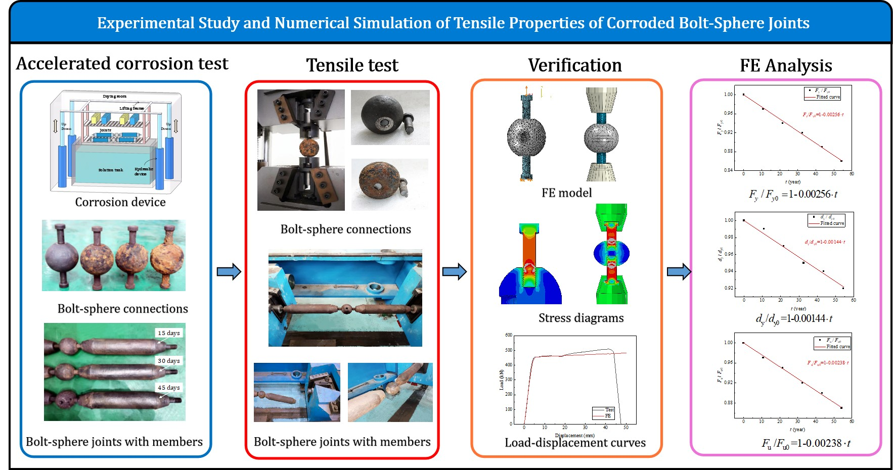
Article

Experimental Study and Numerical Simulation of the Tensile Properties of Corroded Bolt-Sphere Joints

1
School of Civil Engineering, Tianjin University, Tianjin 300072, China
2
CCCC Fourth Highway Engineering Co., Ltd., Beijing 100022, China
3
Key Laboratory of Coast Civil Structure Safety, Ministry of Education, Tianjin University, Tianjin 300072, China
*
Author to whom correspondence should be addressed.
Buildings 2022, 12(11), 1989; https://doi.org/10.3390/buildings12111989
Submission received: 19 October 2022 / Revised: 14 November 2022 / Accepted: 14 November 2022 / Published: 16 November 2022
(This article belongs to the Special Issue Performance Evaluation and Improvement of Corroded Steel Structures)

Abstract

:
In order to study the mechanical behavior of corroded bolt-sphere joints and predict the bearing capacity of the joints in a corrosive environment, bolt-sphere-connection and bolt-sphere-joint specimens with differing degrees of corrosion were obtained by accelerated corrosion. The tensile properties of the corroded bolt-sphere connections and the bolt-sphere joints with members were tested, respectively, and the effects of different degrees of corrosion on the tensile properties of bolted spherical joints were studied. Finally, a numerical simulation of the corroded bolt-sphere connections and bolt-sphere joints with members was carried out, and the main factors affecting the tensile performance of the corroded bolt-sphere joints was clarified; the degradation law of the tensile properties of the bolted sphere joints with service time was established.

Graphical Abstract

1. Introduction

Bolt-sphere joints are one of the most widely used spatial joints at present, with the advantages of convenient construction and reasonable mechanical properties. Corrosion is inevitable for bolt-sphere joints exposed to corrosive environments, such as industry and the marine atmosphere. In practical engineering applications, despite protective measures (e.g., paint) being taken, serious corrosion problems may still occur, as is shown in Figure 1. Corrosion may reduce the mechanical properties of bolt-sphere joints, which has a negative impact on the safety and durability of space structures. Therefore, it is necessary to study the residual performance of the corroded bolt-sphere joints and the evaluation method for this, which can provide a basis for the evaluation, repair, and reinforcement of space structures.
Extensive research into bolt-sphere joints has been carried out internationally [1,2,3,4]. Ahmadizadeh et al. [5] investigated the effects of socket joint deformability on the behavior of space grid structures. Fan et al. [6] obtained the compressive and tensile calculation criteria of bolt-sphere joints and verified that the bolt-sphere joint has certain rotational stiffness and is a semirigid joint. In the Technical Specification for Space Grid Structures (JGJ 7-2010) [7], the tensile and compressive properties of bolted sphere joints are also systematically described. Wu et al. [8] studied the effect of an insufficient screwing depth of the bolt on the mechanical behavior of the bolt-ball joint and the stability of the single-layer reticulated shell. Liu et al. [9] predicted the bearing performance degradation of pitted bolt-sphere joints by FE modeling with the incorporation of stochastic corrosion pits. Liu et al. [10] investigated the effects of material type, high temperatures, and cooling modes on the tensile properties of postfire bolt-sphere joints by conducting tensile tests on 15 steel bolt-sphere joints and 15 aluminum bolt-sphere joints. Xing et al. [11] studied the mechanical properties of 40Cr and 35CrMn high-strength bolts of 10.9s grade, which are commonly used in grid structures after fires by controlling the fire temperature and the cooling mode. Huang et al. [12] investigated the tensile properties of four sets of 36 bolt-sphere joints, consisting of M20, M24, M30, and M36 high-strength bolts under fire. Lei et al. [13] carried out constant amplitude fatigue tests on M20 high-strength bolts in a grid structure with bolt–sphere joints and proposed a calculation method for the constant amplitude fatigue of high-strength bolts. Yan et al. [14] performed a study on detecting bolt-sphere joints’ looseness in steel grid structures and established the relationship between ultrasonic energy attenuation and the level of bolt loosening. Piroglu et al. [15] presented investigations on a Mero double-layer grid steel space truss roof (of an industrial plant) which partially collapsed after exceptional snowfall.
Overall, fundamental research into the tensile mechanical properties of corroded bolt-sphere joints is still lacking. In this paper, bolt-sphere connections and bolt-sphere joints with different degrees of corrosion were examined. Firstly, different degrees of bolt-sphere connection and bolt-sphere joint corrosion were obtained by cyclic wet–dry immersions. Then, tensile tests on the corroded bolt-sphere connections and bolted sphere joints were carried out, respectively, and the influence of corrosion on the tensile properties was analyzed. Finally, a numerical simulation of the corroded bolt-sphere connections and bolt-sphere joints was carried out, and the main factors affecting the tensile performance were clarified.

2. Experimental Program

2.1. Specimen Design

In order to study the tensile properties of the bolt-sphere connection and bolted sphere joint members under different degrees of corrosion, four bolted sphere connections and four bolted spherical joints (with members) were designed according to the Technical Specification for Space Grid Structures (JCJ7-2010) [7] and the Code for Design of Steel Structures (GB 50017-2003) [16]. The bolt-sphere connection consists of two 10.9 grade M20 high-strength bolts and one bolt-sphere with a diameter of 100 mm. The basic parameters of the specimen are shown in Figure 2 and Table 1. The bolt-sphere joint is composed of two Φ88.5 × 4.5 round steel tubes, four 10.9 grade M27 high-strength bolts, and one bolt-sphere joint, where the diameter of the bolt sphere is 100 mm. The basic parameters of the specimen are shown in Figure 3 and Table 2.
The high-strength bolts are made of 40Cr; the bolt-sphere material is 45 steel, and the material of the specific member is Q355. The chemical composition of these three types of steel is shown in Table 3. The depth of the bolt screwed into the sphere in the specimen is 1.1 times the diameter of the bolt to ensure that the shear bearing capacity of the thread connected by the high-strength bolt is greater than the tensile bearing capacity of the rod. Since this paper focuses on the tensile properties of the joints, the effect of the sleeve is not considered.

2.2. Accelerated Corrosion

One of the bolt-sphere connections or bolt-sphere joints (with members) was used as the basic specimen, and the other three specimens were put into the ZY-TL-C1 accelerated corrosion device, which is composed of a solution tank, a drying room with adjustable temperature and humidity, and a lifting frame where the specimens are placed, as shown in Figure 4a. The specimens were immersed in the corrosion solution after the lifting frame lowered; when the lifting frame was elevated, the specimen emerged from the solution and entered the preset drying environment, as shown in Figure 4b. When considering the corrosion behavior of steel in a polluted marine atmosphere, the mass fraction of NaCl in the solution was set to 3.5% according to the standard GB/T 19746-2005 [17]. The period of one cycle of accelerated corrosion was set to be 60 min in total, including 15 min of immersion and 45 min of drying. The solution temperature in the corrosion device was maintained at (20 ± 2) °C, while the air temperature in the drying environment was set to (45 ± 2) °C.
It is worth noting that this paper is different from previous related studies [18]. In previous studies, the bolt-sphere and the bolts were rusted separately, and then the two were assembled for testing; in this paper, the high-strength bolt and the member were installed on the bolt-sphere first, and then put into the corrosion environment as a whole specimen for accelerated corrosion, as shown in Figure 4c. The method of accelerated corrosion after installation can better reflect the influence of real atmospheric corrosion.

2.3. Loading of the Specimens

2.3.1. Bolt-Sphere Connections

The loading device on the bolt-sphere connections was a 100t WAW-1000 testing machine. Firstly, the high-strength bolt was screwed into the steel ball, and then the specimen was fixed onto the testing machine by a matched fixture to ensure that the center of the specimen was aligned with the center of the testing machine. During the experiment, the loading speed was 2 mm/min until the bolt-sphere connection was damaged or the bearing capacity was reduced to less than 50% of the ultimate bearing capacity, and the ultimate bearing capacities and load-displacement curves of the bolt-sphere connections under different degrees of corrosion were recorded.

2.3.2. Bolt-Sphere Joints with Members

The tensile tests on the bolt-sphere joints with members were carried out in a 1000t SDSJ-1000 horizontal tensile machine. Firstly, the high-strength bolt was screwed into the steel ball, and then another high-strength bolt in the rod was screwed into the fixture matched with the high-strength bolt. To ensure the testing result, the depth of the bolt screwed into the ball in the test piece was greater than 1.1 times the diameter of the bolt. Finally, the chuck was fixed with the testing machine to complete the installation of the test piece.

3. Test Phenomenon and Results

3.1. Corroded Specimens

3.1.1. Corroded Bolt-Sphere Connections

The corroded bolt-sphere connections are shown in Figure 5. It can be seen that the bolt-sphere connections (after corrosion) were covered by yellow-brown corrosion products. The outer surface of the high-strength bolt with accelerated corrosion for 15 days and 30 days was slightly corroded. The corrosion products of the high-strength bolt with accelerated corrosion for 45 days were connected to the corrosion products of the bolt-sphere, and the whole surface of the specimen was covered by the corrosion products.
A mechanical grinding method was adopted to remove the rust on the specimens; that is, using an electric angle grinder with a wire brush to grind the specimen to remove the rust products on its surface. The mass loss of the specimens was recorded as w and calculated using Equation (1). A precise electronic balance with an accuracy of 0.01 kg was employed to measure and record the initial weight of the specimen and the weight of the specimen after accelerated corrosion [19,20,21].
w = Δ m m 1 × 100 %
where m1 is the initial mass, m2 is the mass of the specimen after rust removal, and Δm = m1m2 is the change in mass of the specimen after accelerated corrosion. The measured values of the mass losses for the four specimen groups are listed in Table 4.

3.1.2. Corroded Bolt-Sphere Joints with Members

In the same way, the rust of the bolt-sphere joints with members was removed by mechanical grinding, as shown in Figure 6. In the process of rust removal, it was found that, with an increase in the degree of corrosion, the corrosion products become denser, the surface of the members becomes rougher, and the depth of the corrosion increases.
The derusted bolt-sphere joints with members were weighed and subjected to weight loss analysis, and the specific results are shown in Table 5.

3.2. Failure Modes

3.2.1. Corroded Bolt-Sphere Connections

For a bolt-sphere connection, no matter whether it is rusted or not, the deformation of the bolt-sphere is small. The fracture of the bolt occurred at the interface between the bolt-sphere and the screw, which is the junction between the smooth section of the bolt rod and the threaded section. The fracture started from the arc chamfer of the thread groove, and there was no obvious deformation of the bolt-sphere, as shown in Figure 7. The fractures of individual specimens are shown in Figure 8. It can be seen that the modes of failure of the bolt-sphere connections with different degrees of corrosion are consistent with those of the uncorroded specimens; all specimens fractured at the high-strength bolts, and no obvious deformation occurred on the bolt-sphere; that is, corrosion has little effect on the tensile failure modes of bolt-sphere connections.

3.2.2. Corroded Bolt-Sphere Joints with Members

For the bolt-sphere joints with members, all the specimens had fractured at the high-strength bolts. The failures of the uncorroded specimen and the specimen subjected to accelerated corrosion for 30 days occurred where the high-strength bolt is connected to the chuck, while the failures of the specimen subjected to accelerated corrosion for 15 days and the specimen subjected to accelerating corrosion for 45 days occurred where the high-strength bolt is connected to the bolt-sphere, as shown in Figure 9.
It can be seen from Figure 9 that the corroded bolt-sphere joints with members still had good bearing capacities, and the fractures of the specimens under different degrees of corrosion occurred at the connection between the high-strength bolts, indicating that the bearing capacity of the corroded members is greater than those of the corroded high-strength bolts, and the rusted members still have high safety reserves.

3.3. Load-Displacement Curves

3.3.1. Corroded Bolt-Sphere Connections

Figure 10 shows the comparison between the load-displacement curves of the corroded bolt-sphere connections. The yield load (Fy), yield displacement (dy), ultimate load (Fu), and ultimate displacement (du) of the bolt-sphere connections under different degrees of corrosion were calculated with the equivalent elastoplastic energy method, as shown in Table 6 [22].
When compared with the uncorroded specimen, the yield load of specimen C-1 decreased by 0.83%, the yield load of specimen C-2 decreased by 3.02%, and the yield load for the specimen with the corroded degree of 4.44% decreased by 9.4 kN, accounting for 4.16% of the yield load for the uncorroded specimen. The ultimate tensile loads of all specimens changed a little, and the ultimate tensile load of the specimen corroded for 45 days decreased by 8.51 kN compared with the uncorroded specimen, accounting for a drop of 3.11% in the ultimate load of the uncorroded specimen. According to the analysis results, the influences of corrosion on the stiffness, yield load, and ultimate load of bolt-sphere connectors was less than 5%, indicating that the influences of corrosion on the tensile properties of bolt-sphere connectors are small.

3.3.2. Corroded Bolt-Sphere Joints with Members

Figure 11 and Table 7 show the load-displacement curves and key mechanical parameters of the bolt-sphere joints with members. It can be seen that there are almost no changes in the tensile stiffness of the bolt-sphere joints with members; that is, corrosion has little effect on the tensile stiffnesses of the bolt-sphere joints with members. The yield load and yield displacement of the bolt-sphere joints with members decrease with the increase in the degree of corrosion. When the degree of corrosion reaches 5.62%, the tensile yield load of the joint decreases by 47.6 kN, which is 10.46% of the joint without corrosion.
To further analyze the influence of corrosion on the mechanical properties of bolt-sphere joints with members, the atmospheric corrosion rates of Q355B, 45 steel, and 40Cr were compared in this paper. The average corrosion rate of different steels in the Beijing area of China over 16 years (accessed via the China Corrosion and Protection Website) is shown in Table 8. According to Table 8, the corrosion rate of Q355B is greater than that of 45 steel and 40Cr in the same atmospheric environment, and the corrosion rate of Q355B is about 1.49 times that of 45 steel and 1.93 times that of 40Cr. According to the test results of the bolt-sphere connections, the effect of corrosion on the tensile performance of the bolt-sphere joints with members is more significant; that is, the degradation of the tensile performance of the corroded bolt-sphere joints with members is mainly caused by the corroded members.

4. Simulation of the Corroded Bolt-Sphere Joints with Members

4.1. Model Information

In this paper, the thread of a high-strength bolt was modeled according to the thread dimensions specified in the General Purpose Metric Screw Threads—Basic Dimensions (GB/T 196-2003) [23], as shown in Figure 12 and Table 9.
The uncorroded material properties of each component in the FE model refer to the High Strength Bolts for Joints of Space Grid Structures (GB/T16939-2016) [24] and the Quality Carbon Structure Steels (GB/T 699-2015) [25], as shown in Table 10. The double-broken line model was adopted for the constitutive relationships between the three kinds of steel in the FE model.
In ABAQUS, the General Contact function was adopted to model the mutual contact between the components; the properties of the contact were Hard Contact in the normal direction, and the tangential friction coefficient was 0.2 [26]. The tetrahedral element (C3D10M) was selected as the mesh type for the bolt-sphere and high-strength bolts [27]. The mesh was refined in the areas with large stresses, such as the thread connection, while the mesh in other areas was relatively loose, which can not only reduce the calculation time and improve the calculation efficiency but also ensures the accuracy of the analysis results. For the bolt-sphere connections, a fixed constraint was applied to the bottom surface of the high-strength bolt, and a displacement load was applied to the surface of another high-strength bolt, as shown in Figure 13. The bolt-sphere joints with members were loaded in the same way as the bolt-sphere connections, as shown in Figure 14.

4.2. Comparison and Verification

The above material constitutive and modeling methods were used for the numerical simulation of the uncorroded bolt-sphere connections, and the load-displacement curves and stress diagrams of the bolt-sphere connections are shown in Figure 15 and Figure 16.
The load-displacement curve obtained by the numerical simulation is consistent with the experimental curve, and the initial stiffnesses are almost coincident. The yield load obtained by the finite element method is 3.6% larger than the experimental value, and the difference between the ultimate tensile load obtained by the numerical simulation and the experimental value is 5.1%, both of which are within 10%. The results of the finite element analysis show that the stress concentration is the most obvious at the juncture between the smooth part and the threaded part of the bolt in the initial loading stage. With the increase in displacement load, the plastic state first occurred here, and then the specimen fractured at this location, which is consistent with the failure mode in the test. Figure 17 shows the comparison between the load-displacement curves of the uncorroded bolt-sphere joints with members from the test and FE. The calculation results of the finite element model of the joint are in good agreement with the test values, and the only difference at the ultimate tensile load on the postloading portion is 6.7%.
Figure 18 shows the stress diagrams of the uncorroded bolt-sphere joint with members during the loading process. The stress development state of the bolt-sphere joint with members is the same as that of the bolt-sphere connection, which shows that the junction between the smooth segment and the threaded segment of the bolt rod first enters the plastic state. In addition, according to the stress diagrams, it can be concluded that, during the loading process, the high-strength bolt first entered a plasticity state, and then the members entered a plasticity state. When the high-strength bolt reached the ultimate strength, the member was still in a plastic state, and the stress level of the member did not reach the ultimate strength; therefore, the failure of the bolt-sphere joint with members occurred at the location of the high-strength bolt, which is consistent with the experimental results.

4.3. Parameter Analysis

In order to further analyze the tensile performance of the corroded bolt-sphere joints with members, the finite element model of the corroded bolt-sphere joints with members is simplified in this paper, according to the test result that corrosion has little effect on the mechanical performance of the bolt-sphere connections, and that the degradation of the tensile performance of the corroded bolt-sphere joints with the bars is mainly caused by the members. Therefore, in the corroded FE model, only the effect of the corrosion of the member on the tensile behavior of the bolted sphere joints with members was considered.
The mechanical behaviors [28,29,30,31,32] and fatigue properties [33,34,35,36,37,38,39,40] of corroded steel have been studied by various scholars. The material of the member in the bolt-sphere joint is Q355B steel, and the existing research shows that the degradation of the mechanical properties of the corroded Q355B steel meets the following laws [41], as shown in Equations (2)–(5).
E / E = 1 0.01015 · w
f y / f y = 1 0.01359 · w
ε u / ε u = 1 0.01765 · w
f u / f u = 1 0.01646 · w
The above formulas were adopted to calculate the mechanical properties of the corroded Q355B steel, and the mechanical parameters of Q355B under different degrees of corrosion are shown in Table 11.
The numerical simulation was carried out for the bolt-sphere joints with members under three different degrees of corrosion corresponding to the experimental study. The load-displacement curves obtained from the simulation are shown in Figure 19, and the comparison results between the mechanical parameters obtained from the simulation and the test are shown in Table 12.
It can be concluded from the comparison results that the FE results and the test results under different degrees of corrosion almost coincide regarding joint stiffness; the maximum difference is 2.92% in the yield load, and the maximum difference is 11.96% in the ultimate tensile load, which indicates that the FE results of the simplified corroded bolt-sphere joint with members are in good agreement with the test results. The simplified FE model can accurately reflect the variations in the tensile strength of the bolt-sphere joints with members under different degrees of corrosion.
The above simplified FE model was adopted to numerically analyze the tensile performance of the bolt-sphere joints with members under different degrees of corrosion; the load-displacement curves are shown in Figure 20, and the key mechanical parameters are shown in Table 13.
In order to conveniently compare the degradations of the mechanical properties of bolt-sphere joints under different service lives, this paper assumes that corrosion only occurs on the outer surface of the specimen. The relationship between the mass loss rate and service life (t) was established according to the corrosion rate in Table 8, and a normalization analysis of the bolt-sphere joints with members in a corrosive environment was carried out. The specific results are shown in Table 14. Linear fittings were performed to the results, and the fitting results are shown in Figure 21.
Comparing the slopes of the three curves, it is obvious that the yield load of the joint decreases fast, while the changes in the yield displacement are small, which indicates that corrosion has a great influence on the elastic bearing capacity of the joint. The least squares method was adopted to establish the quantitative relationships between the mechanical properties and service time (t). The expressions are shown as follows.
F y / F y 0 = 1 0.00256 · t   ( R 2 = 0.999 )
d y / d y 0 = 1 0.00144 · t   ( R 2 = 0.998 )
F u / F u 0 = 1 0.00238 · t   ( R 2 = 0.999 )

5. Conclusions

In order to study the degradation of the tensile mechanical properties of the corroded bolt-sphere connections and bolt-sphere joints with members, accelerated corrosion tests were carried out, and the experimental study and finite element simulation of the bolt-sphere connections and bolt-sphere joints with members under different degrees of corrosion were carried out. The specific conclusions are as follows.
(1) Bolt-sphere connections with different degrees of corrosion fractured at the junction between the smooth and threaded sections of the bolt rod. When the weight loss of the bolt-sphere connection reaches 4.44%, the influences of corrosion on the stiffness, yield load, and ultimate load of the bolt-sphere connection were less than 5%, and the influences of corrosion on the tensile properties of the bolt-sphere connection were small.
(2) The corroded bolt-sphere joints with members still have a good bearing capacity, and the fractures of the joint under different degrees of corrosion all occurred on the high-strength bolts, which indicates that the bearing capacity of the corroded member of this size is greater than that of the high-strength bolt, and the corroded members have high safety reserves. Under the same atmospheric environment, the corrosion rate of Q355B is about 1.49 times that of 45 steel and 1.93 times that of 40Cr. The degradation of the tensile properties of the corroded bolt-sphere joints with members is mainly caused by the corrosion of the Q355B members.
(3) The finite element models of the bolt-sphere connections and bolt-sphere joints with members were established, and the parametric analysis of the bolt-sphere joints with specimens under different degrees of corrosion was carried out. The results of the simplified finite element model are in good agreement with the experimental results, which shows that the simplified FE model can effectively consider the influence of corrosion on the tensile behavior of the bolt-sphere joints with members and can quickly calculate the mechanical properties of the joints. Based on the results of the finite element analysis, the degradation laws for the tensile properties of the bolt-sphere joints with members over different service periods have been established.

Author Contributions

Data curation, B.K.; Formal analysis, H.L.; Investigation, Y.T.; Writing—original draft, Q.S.; Writing—review & editing, L.Z. All authors have read and agreed to the published version of the manuscript.

Funding

The reported research work was sponsored by the Natural Science Foundation of China (Grant No. 52278200).

Data Availability Statement

Not applicable.

Acknowledgments

The authors gratefully acknowledge the funding (Grant No. 52278200) from the Natural Science Foundation of China.

Conflicts of Interest

The authors declare no conflict of interest.

References

  1. Pieraccini, L.; Palermo, M.; Trombetti, T.; Baroni, F. The role of ductility in the collapse of a long-span steel roof in North Italy. Eng. Fail. Anal. 2017, 82, 243–265. [Google Scholar] [CrossRef]
  2. Chenaghlou, M.R.; Nooshin, H. Axial force–bending moment interaction in a jointing system part I: (Experimental study). J. Constr. Steel Res. 2015, 113, 261–276. [Google Scholar] [CrossRef]
  3. Caglayan, O.; Yuksel, E. Experimental and finite element investigations on the collapse of a Mero space truss roof structure—A case study. Eng. Fail. Anal. 2008, 15, 458–470. [Google Scholar] [CrossRef]
  4. Doaei, Y.; Aghakouchaki Hosseini, S.E.; Momenzadeh, A.; Harirchian, E. Investigating the effect of screw size on the stress level in mero joint for space frame structures. Appl. Syst. Innov. 2021, 4, 84. [Google Scholar] [CrossRef]
  5. Ahmadizadeh, M.; Maalek, S. An investigation of the effects of socket joint flexibility in space structures. J. Constr. Steel Res. 2014, 102, 72–81. [Google Scholar] [CrossRef]
  6. Fan, F.; Ma, H.; Shen, S. Numerical simulation and experimental study on mechanical characters of bolt-ball joint system. Eng. Mech. 2009, 26, 92–99. [Google Scholar]
  7. JGJ 7-2010; Technical Specification for Space Grid Structure. CABP: Beijing, China, 2011.
  8. Wu, Q.; Wang, H.; Qian, H.; Han, K.; Fan, F. Effect of insufficient screwing depth of bolt on mechanical behavior of bolt-ball joint and stability of single-layer reticulated shell. Eng. Struct. 2020, 213, 110590. [Google Scholar] [CrossRef]
  9. Yuan, H.; Liu, H.; Ren, X.; Zhang, X.; Ai, D.; Luo, Y. The bearing performance of the bolt-sphere joints with stochastic pitting corrosion damage. J. Constr. Steel Res. 2019, 160, 359–373. [Google Scholar] [CrossRef]
  10. Liu, H.; Tan, Z.; Chen, Z.; Liu, Z.; Liu, D. Experimental study on residual mechanical properties of bolt-sphere joints after a fire. Int. J. Steel Struct. 2018, 18, 802–820. [Google Scholar] [CrossRef]
  11. Feng, S.; Xing, K.; Wang, X.; Xin, L.; Xiao, S. Experimental study on mechanical properties of high strength bolts used in steel grid bolted spherical joints after fire. J. Build. Struct. 2021, 42, 198–205. [Google Scholar]
  12. Huang, B.; Lu, M.; Fu, Y.; Yang, F. Experimental investigation on tensile properties of the bolt in sphere joints Under Fire. Int. J. Steel Struct. 2020, 20, 1355–1363. [Google Scholar] [CrossRef]
  13. Yang, X.; Lei, H.; Chen, Y.F. Constant amplitude fatigue test research on M20 high-strength bolts in grid structure with bolt–sphere joints. Adv. Struct. Eng. 2017, 20, 1466–1475. [Google Scholar] [CrossRef]
  14. Yan, S.; Liu, W.; Song, G.; Zhao, P.; Zhang, S. Connection looseness detection of steel grid structures using piezoceramic transducers. Int. J. Distrib. Sens. Netw. 2018, 14, 1550147718759234. [Google Scholar] [CrossRef] [Green Version]
  15. Piroglu, F.; Ozakgul, K. Partial collapses experienced for a steel space truss roof structure induced by ice ponds. Eng. Fail. Anal. 2016, 60, 155–165. [Google Scholar] [CrossRef]
  16. GB50017-2003; Code of Design of Steel Structures. CABP: Beijing, China, 2003.
  17. GB/T19746-2005; Corrosion of Metals and Alloys—Alternate Immersion Test in Salt Solution. CABP: Beijing, China, 2005.
  18. Tan, Z.; Liu, H.; Wang, X.; Du, R. Experimental study and numerical simulation of tensile mechanical properties of bolt-sphere joints after corrosion. Ind. Constr. 2019, 49, 6–11. [Google Scholar]
  19. Wang, Y.; Zhou, X.; Wang, H.; Kong, D.; Xu, S. Stochastic constitutive model of structural steel based on random field of corrosion depth. Case Stud. Constr. Mater. 2022, 16, e00972. [Google Scholar] [CrossRef]
  20. Wang, Y.; Xu, S.; Li, A. Flexural performance evaluation of corroded steel beams based on 3D corrosion morphology. Struct. Infrastruct. Eng. 2020, 16, 1562–1577. [Google Scholar] [CrossRef]
  21. Apostolopoulos, C.; Michalopoulos, D. Effect of corrosion on mass loss, and high and low cycle fatigue of reinforcing steel. J. Mater. Eng. Perform. 2006, 15, 742–749. [Google Scholar] [CrossRef]
  22. Feng, P.; Qiang, H.; Ye, L. Discussion and definition on yield points of materials, members and structures. Eng. Mech. 2017, 34, 36–46. [Google Scholar]
  23. GB/T196-2003; General Purpose Metric Screw Threads—Basic Dimensions. CABP: Beijing, China, 2003.
  24. GB/T16939-2016; High Strength Bolts for Joints of Space Grid Structures. CABP: Beijing, China, 2016.
  25. GB/T699-2015; Quality Carbon Structure Steels. CABP: Beijing, China, 2015.
  26. Zheng, B.; Gu, Y.; Wang, J.; Shu, G.; Jiang, Q. Experimental study on slip factor of stainless steel faying surface. J. Build. Struct. 2021, 42, 154–161. [Google Scholar]
  27. Ebadi Jamkhaneh, M.; Homaioon Ebrahimi, A.; Shokri Amiri, M. Numerical investigation of the behavior of MERO joint system under combined loading regarding helical threads of elements. Int. J. Steel Struct. 2020, 20, 897–909. [Google Scholar] [CrossRef]
  28. Appuhamy, J.M.R.S.; Kaita, T.; Ohga, M.; Fujii, K. Prediction of residual strength of corroded tensile steel plates. Int. J. Steel Struct. 2011, 11, 65–79. [Google Scholar] [CrossRef]
  29. Garbatov, Y.; Parunov, J.; Kodvanj, J.; Saad-Eldeen, S.; Soares, C.G. Experimental assessment of tensile strength of corroded steel specimens subjected to sandblast and sandpaper cleaning. Mar. Struct. 2016, 49, 18–30. [Google Scholar] [CrossRef]
  30. Ahmmad, M.; Sumi, Y. Strength and deformability of corroded steel plates under quasi-static tensile load. J. Mar. Sci. Technol. 2010, 15, 1–15. [Google Scholar] [CrossRef]
  31. Melchers, R.E.; Paik, J.K. Effect of tensile strain on the rate of marine corrosion of steel plates. Corros. Sci. 2009, 51, 2298–2303. [Google Scholar] [CrossRef]
  32. Vukelic, G.; Vizentin, G.; Ivosevic, S. Tensile strength behaviour of steel plates with corrosion-induced geometrical deteriorations. Ships Offshore Struct. 2021, 17, 106–132. [Google Scholar] [CrossRef]
  33. Gehlen, C.; Osterminski, K.; Weirich, T. High-cycle fatigue behaviour of reinforcing steel under the effect of ongoing corrosion. Struct. Concr. 2016, 17, 329–337. [Google Scholar] [CrossRef]
  34. Apostolopoulos, C.A.; Papadopoulos, M.P. Tensile and low cycle fatigue behavior of corroded reinforcing steel bars S400. Constr. Build. Mater. 2007, 21, 855–864. [Google Scholar] [CrossRef]
  35. Fernandez, I.; Bairán, J.M.; Marí, A.R. Corrosion effects on the mechanical properties of reinforcing steel bars. Fatigue and σ–ε behavior. Constr. Build. Mater. 2015, 101, 772–783. [Google Scholar] [CrossRef]
  36. Mhaede, M. Influence of surface treatments on surface layer properties, fatigue and corrosion fatigue performance of AA7075 T73. Mater. Des. 2012, 41, 61–66. [Google Scholar] [CrossRef]
  37. Mansor, N.I.I.; Abdullah, S.; Ariffin, A.K.; Syarif, J. A review of the fatigue failure mechanism of metallic materials under a corroded environment. Eng. Fail. Anal. 2014, 42, 353–365. [Google Scholar] [CrossRef]
  38. Beretta, S.; Carboni, M.; Fiore, G.; Lo Conte, A. Corrosion–fatigue of A1N railway axle steel exposed to rainwater. Int. J. Fatigue 2010, 32, 952–961. [Google Scholar] [CrossRef]
  39. Okayasu, M.; Sato, K.; Okada, K.; Yoshifuji, S.; Mizuno, M. Effects of atmospheric corrosion on fatigue properties of a medium carbon steel. J. Mater. Sci. 2008, 44, 306–315. [Google Scholar] [CrossRef]
  40. Pérez-Mora, R.; Palin-Luc, T.; Bathias, C.; Paris, P.C. Very high cycle fatigue of a high strength steel under sea water corrosion: A strong corrosion and mechanical damage coupling. Int. J. Fatigue 2015, 74, 156–165. [Google Scholar] [CrossRef]
  41. Si, Q.; Ding, Y.; Zong, L.; Zhao, H. Mechanical behaviour of corroded structural steel subjected to monotonic tension. Adv. Steel Constr. 2022, 18, 707–714. [Google Scholar]
Figure 1. Corrosion cases for bolt-sphere joints: (a) Case 1; (b) Case 2; (c) Case 3.
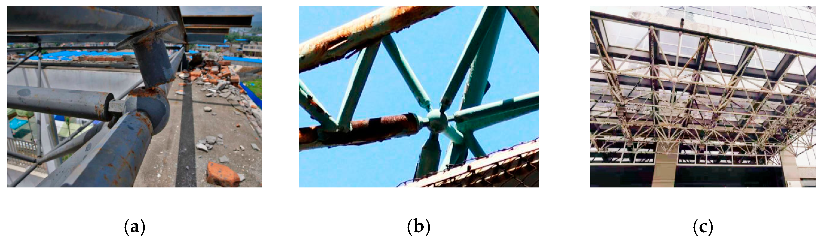
Buildings 12 01989 g001
Figure 2. Bolt-sphere connections: (a) schematic of component dimensions; (b) typical bolt-sphere connections.
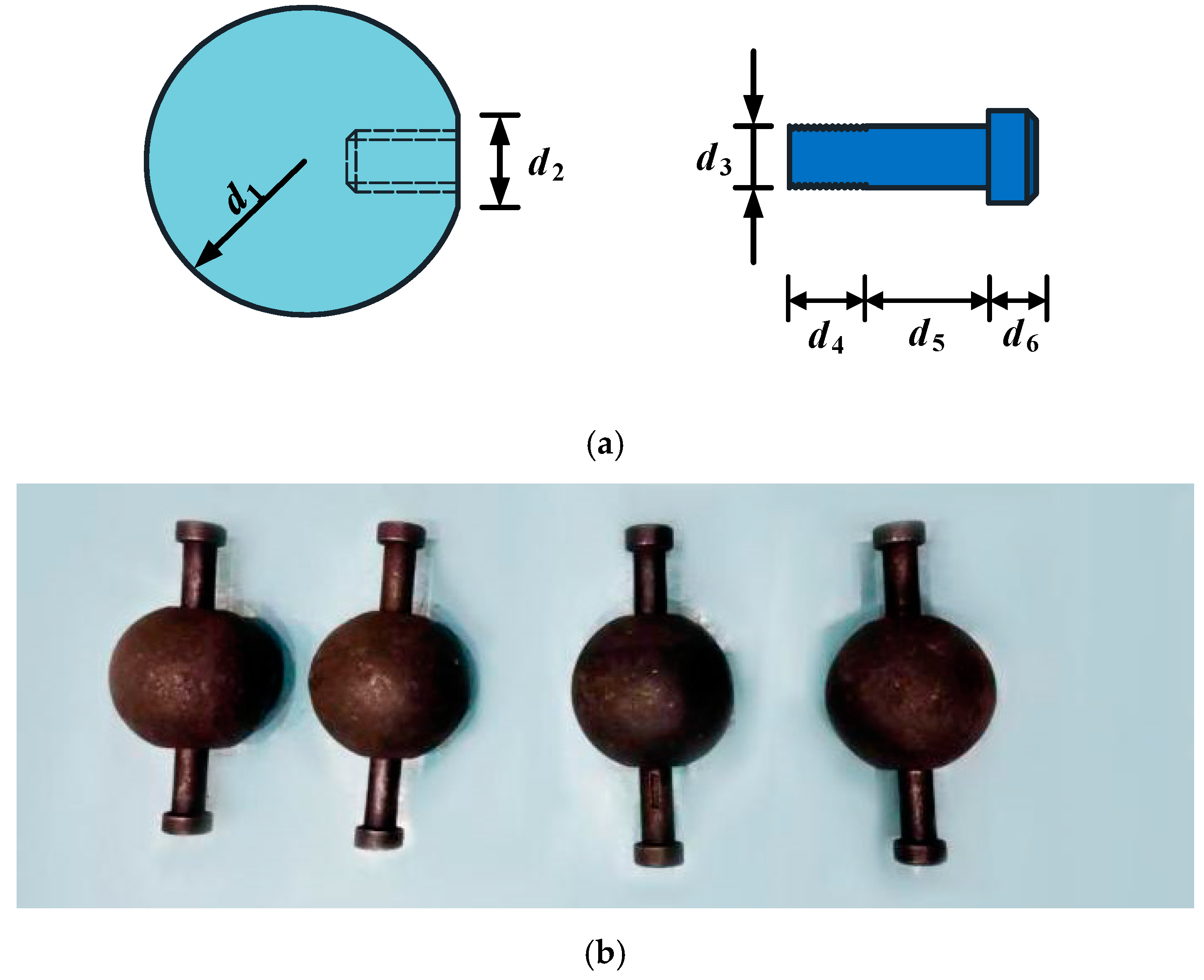
Buildings 12 01989 g002
Figure 3. Bolt-sphere joints with members: (a) schematic of the component dimensions; (b) typical bolt-sphere joints.
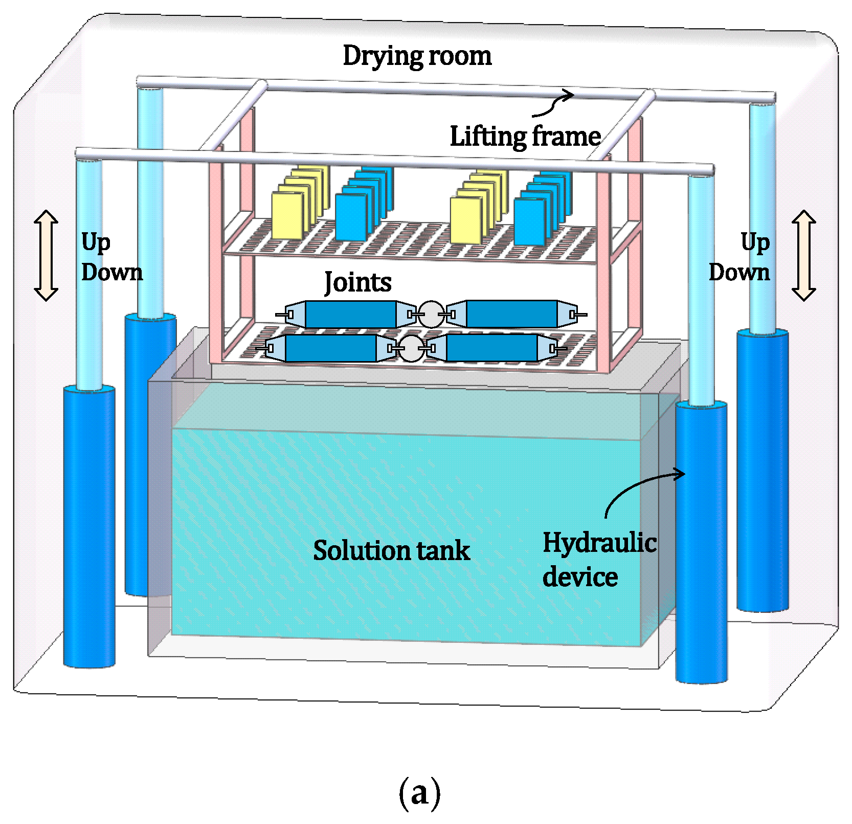
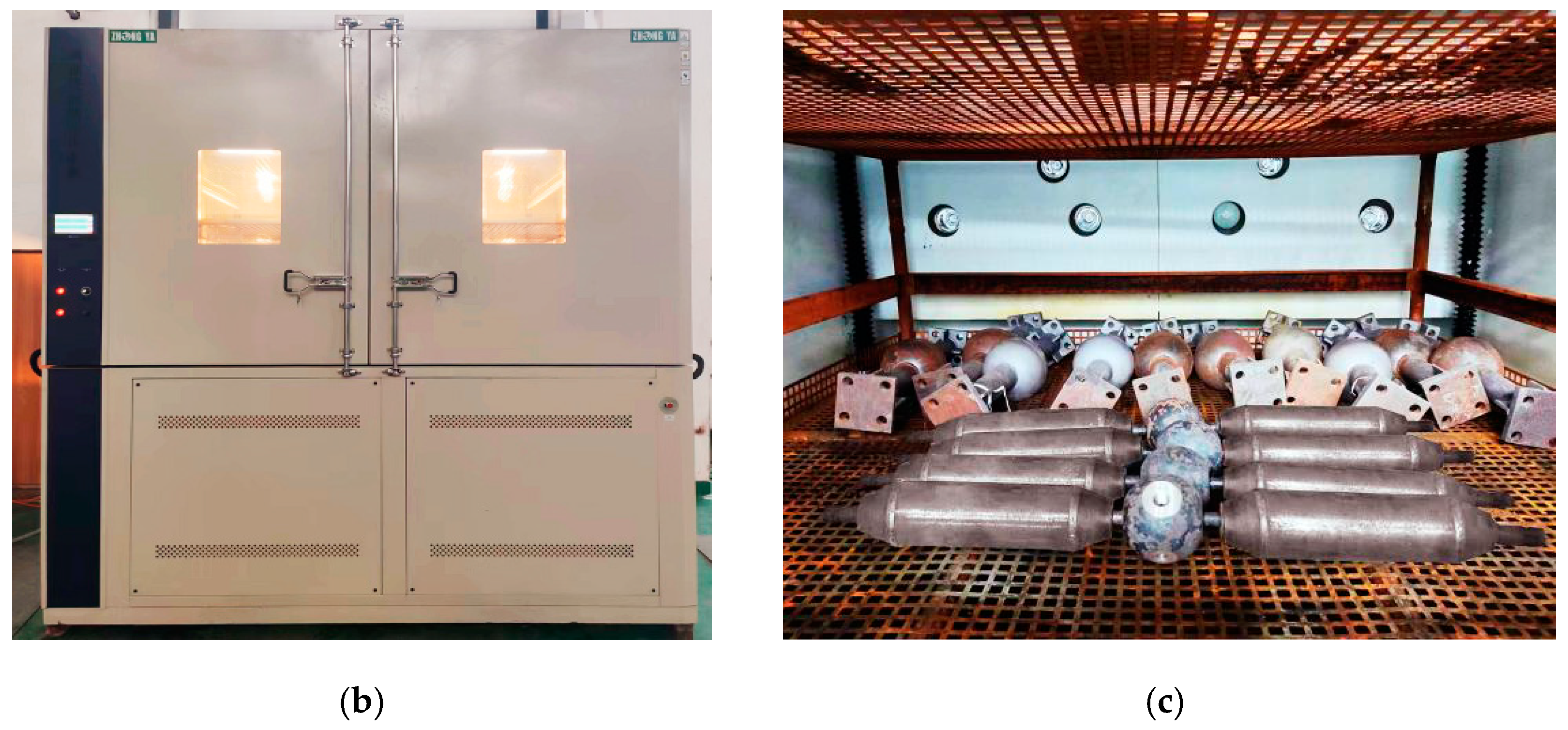
Buildings 12 01989 g003
Figure 4. Accelerated corrosion tests: (a) schematic diagram of ZY-TL-C1 corrosion device; (b) accelerated corrosion device; (c) the joints placed on the lifting frame.
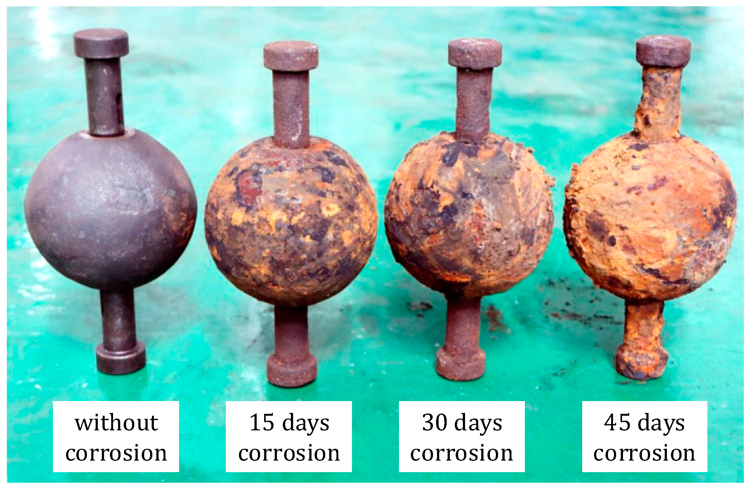
Buildings 12 01989 g004aBuildings 12 01989 g004b
Figure 5. Corroded bolt-sphere connections.
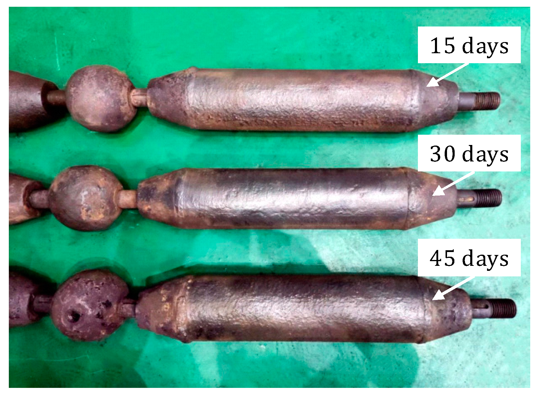
Buildings 12 01989 g005
Figure 6. Corroded bolt-sphere joints with members.
Buildings 12 01989 g006
Figure 7. Failure modes: (a) uncorroded specimen; (b) corroded specimen.
Buildings 12 01989 g007
Figure 8. Fractures of individual specimens: (a) C-0; (b) C-1; (c) C-2; (d) C-3.
Buildings 12 01989 g008
Figure 9. Fractures of individual specimens: (a) J-0; (b) J-1; (c) J-2; (d) J-3.
Buildings 12 01989 g009
Figure 10. Load-displacement curves of the corroded bolt-sphere connections.
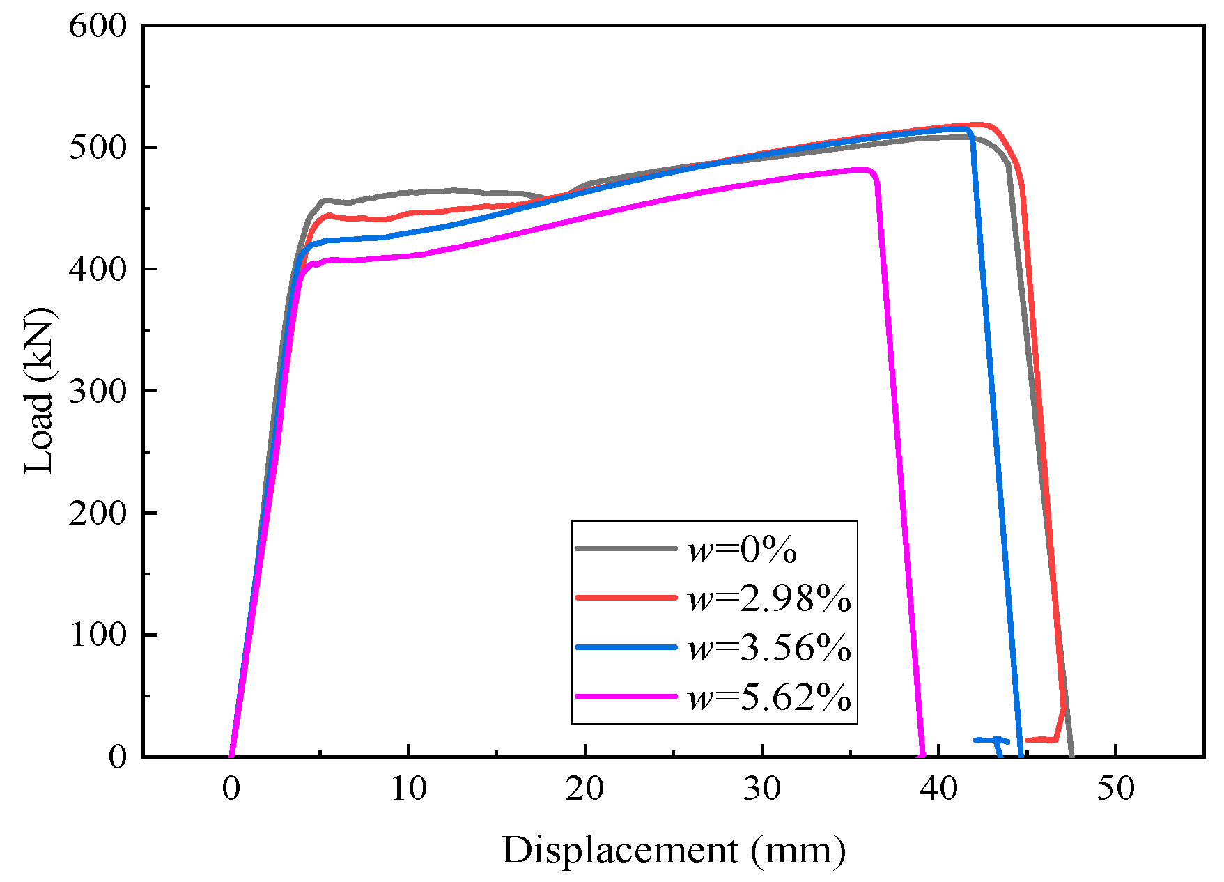
Buildings 12 01989 g010
Figure 11. Load-displacement curves of the corroded bolt-sphere joints with members.
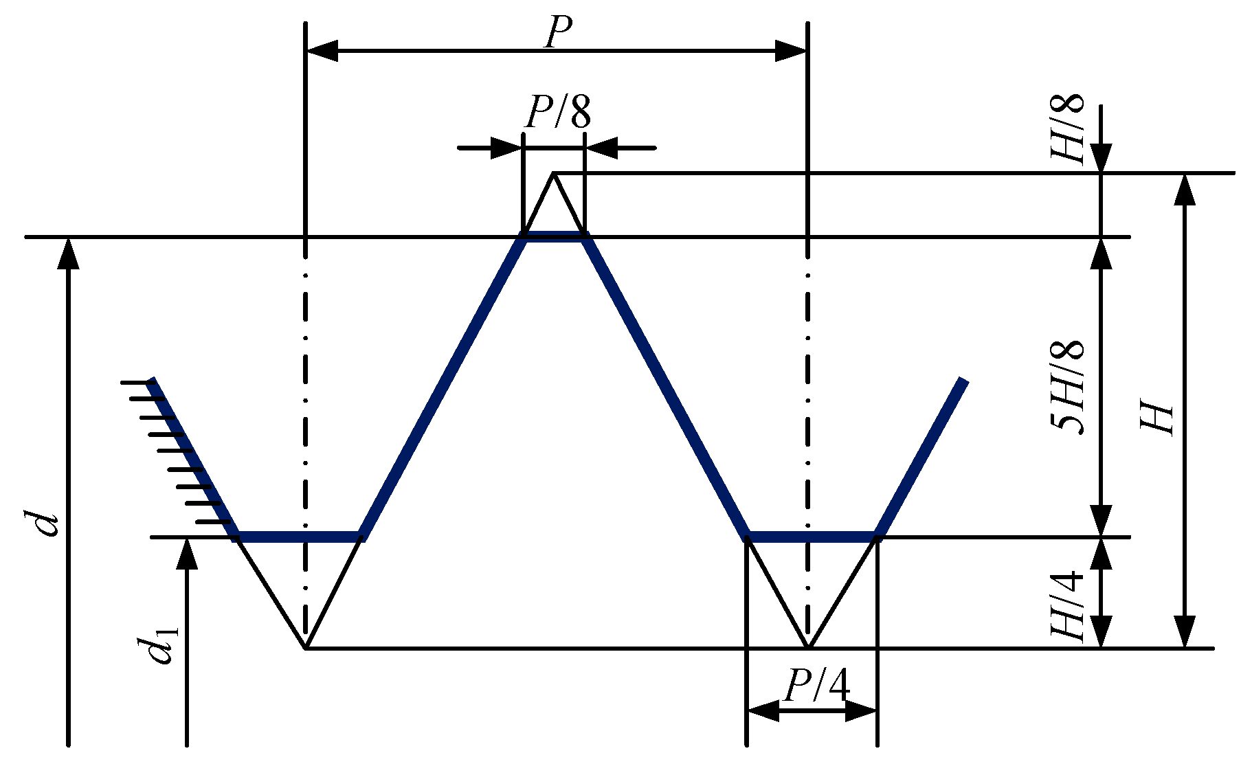
Buildings 12 01989 g011
Figure 12. Diagram of the threads of a typical high-strength bolt.
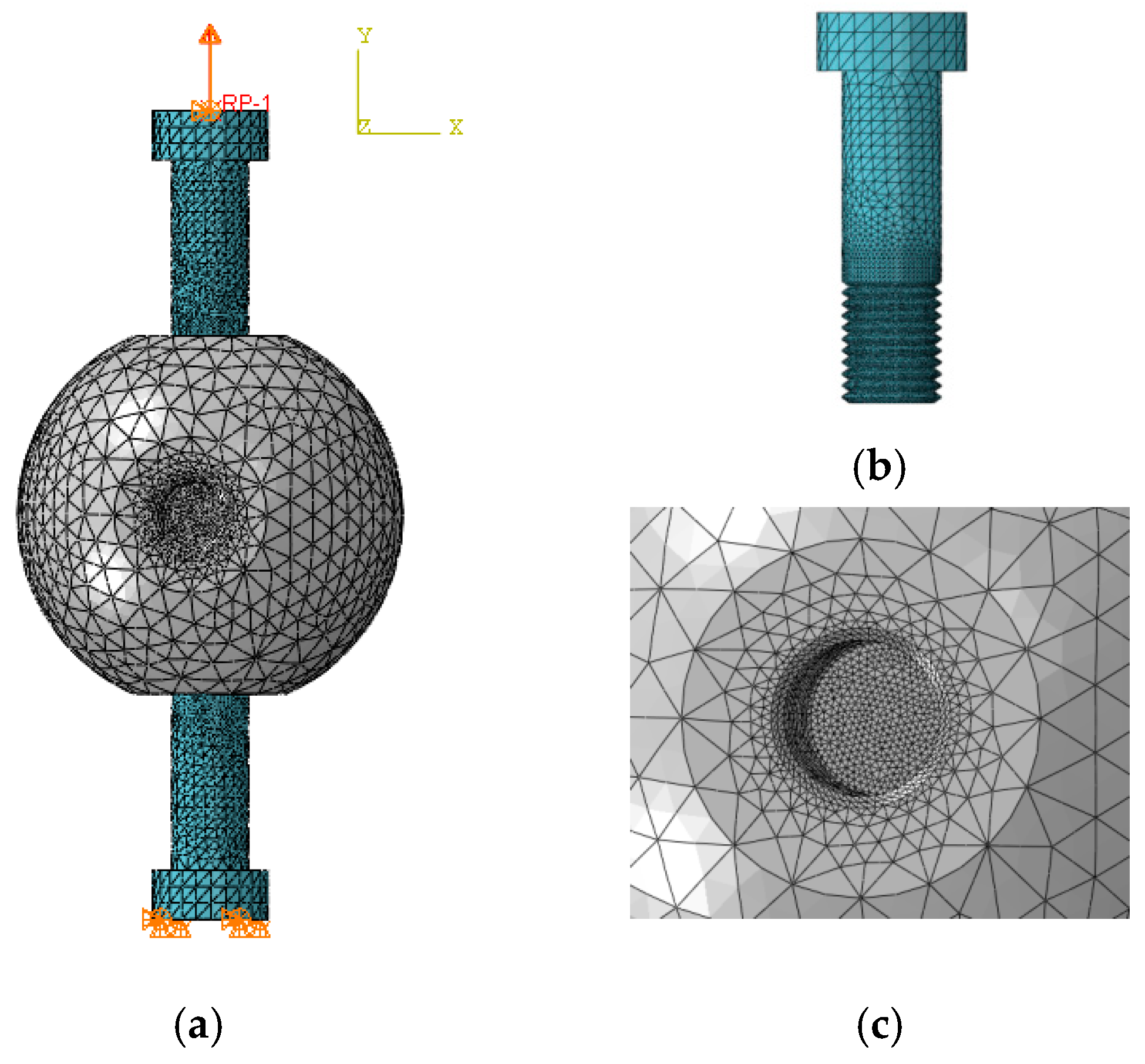
Buildings 12 01989 g012
Figure 13. FE model of a typical bolt-sphere connection: (a) the whole model; (b) the bolt; (c) bolt hole.
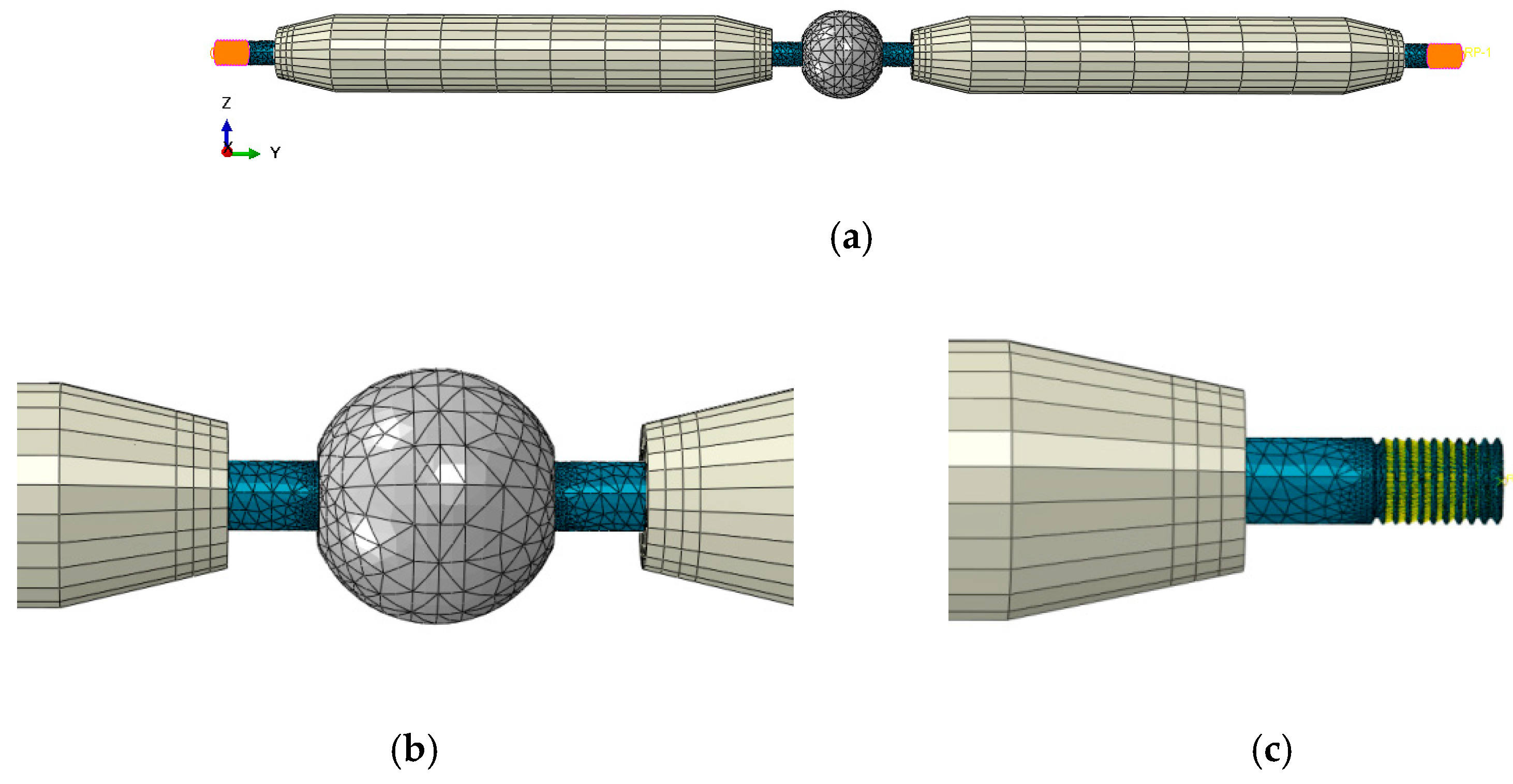
Buildings 12 01989 g013
Figure 14. FE model of a typical bolt-sphere joint with members: (a) the whole mode; (b) the bolt-sphere; (c) the cone-head.
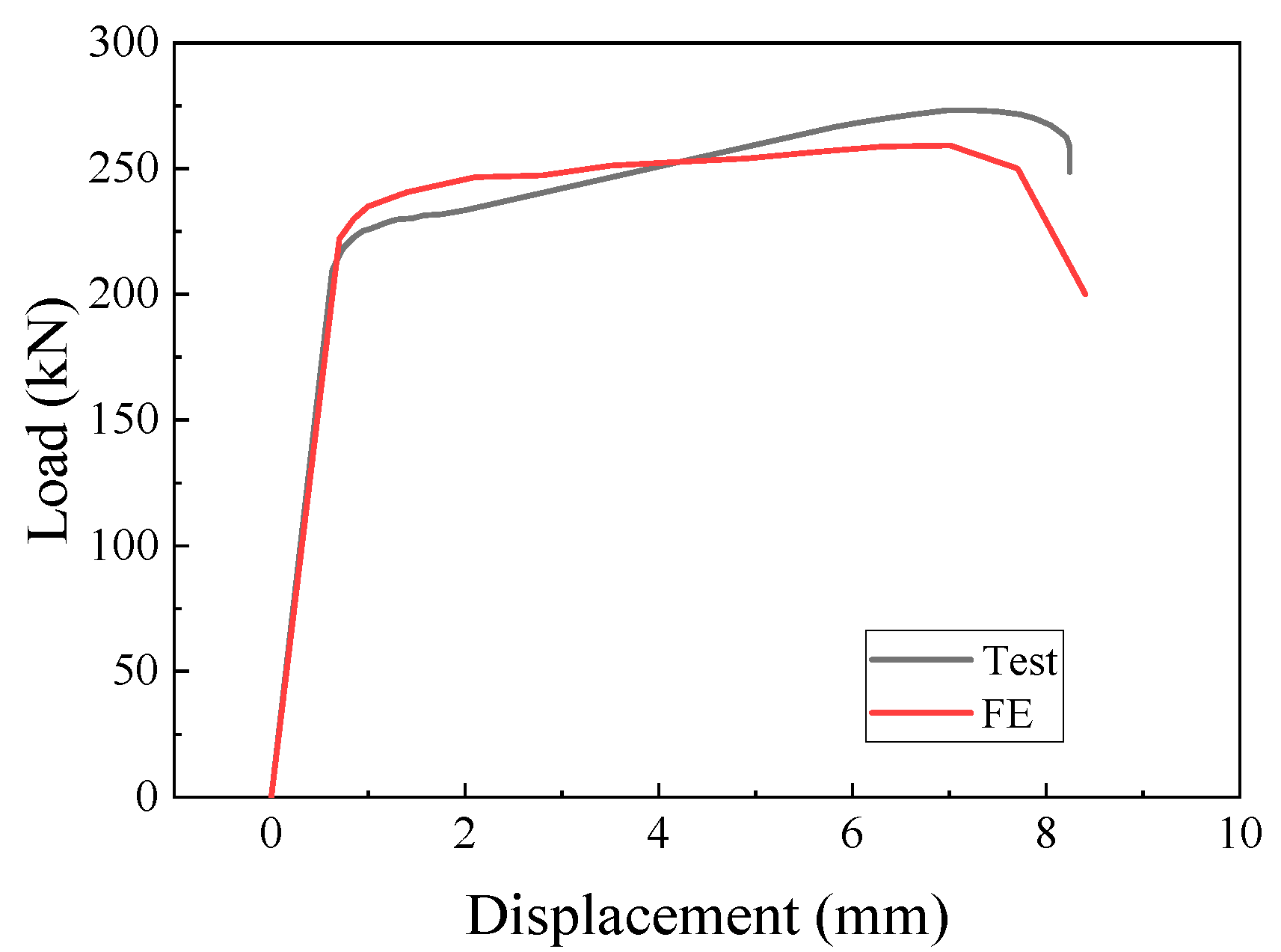
Buildings 12 01989 g014
Figure 15. Load-displacement curves of the bolt-sphere connection from the test and FE.
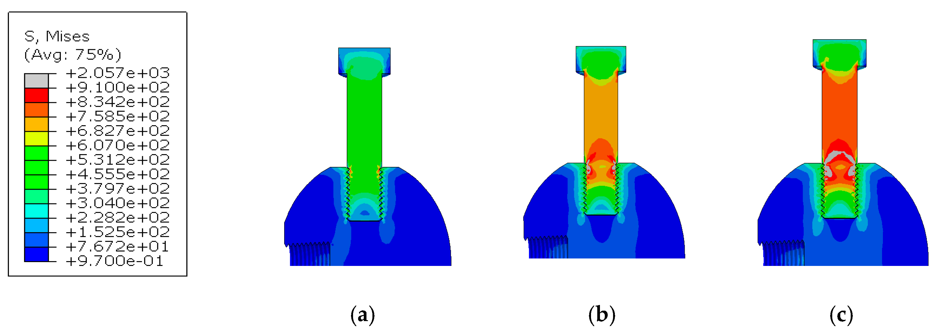
Buildings 12 01989 g015
Figure 16. Stress diagrams of the bolt-sphere connection: (a) initial loading; (b) mid-term loading; (c) postloading.
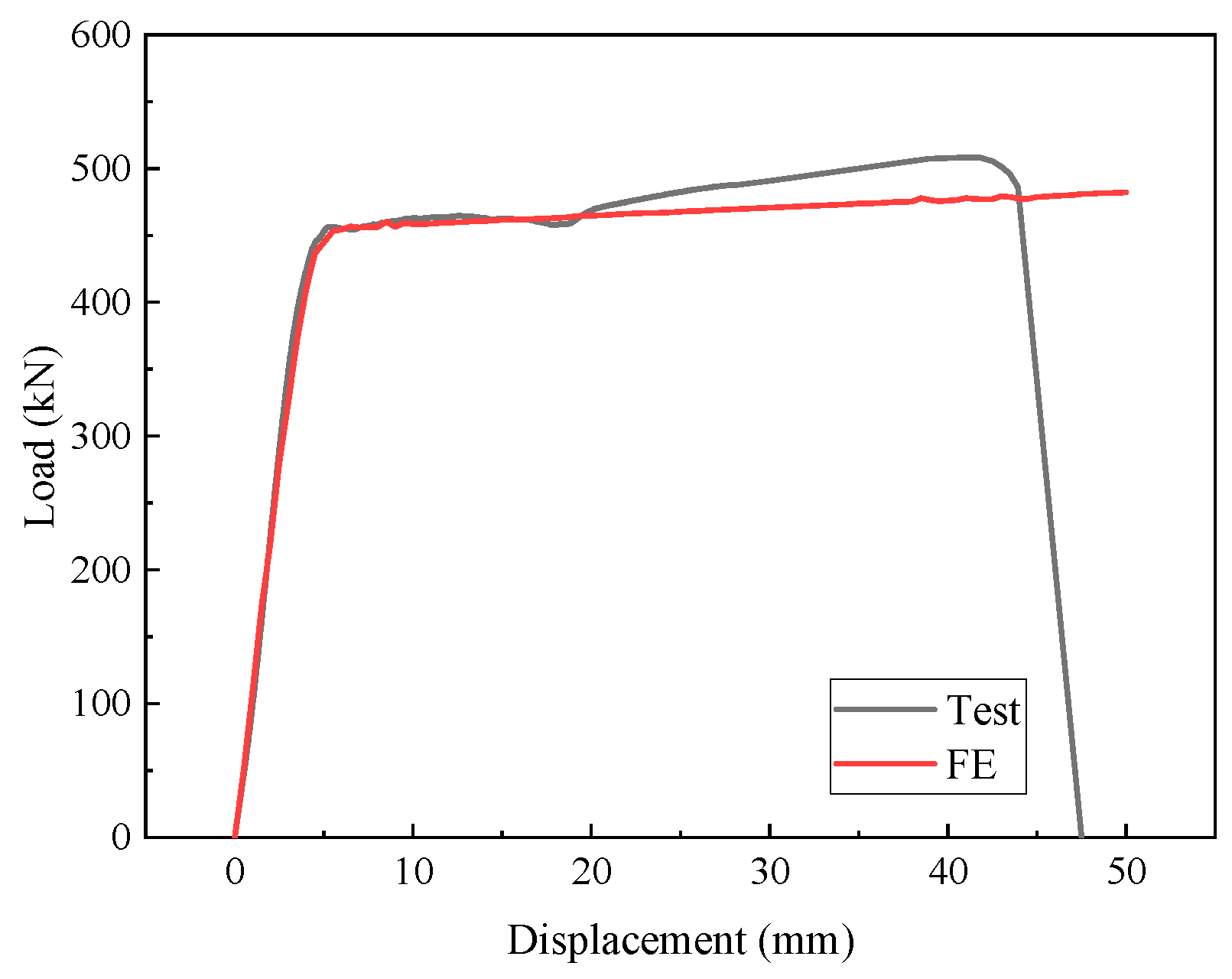
Buildings 12 01989 g016
Figure 17. Load-displacement curves of the bolt-sphere joint with members from the test and FE.
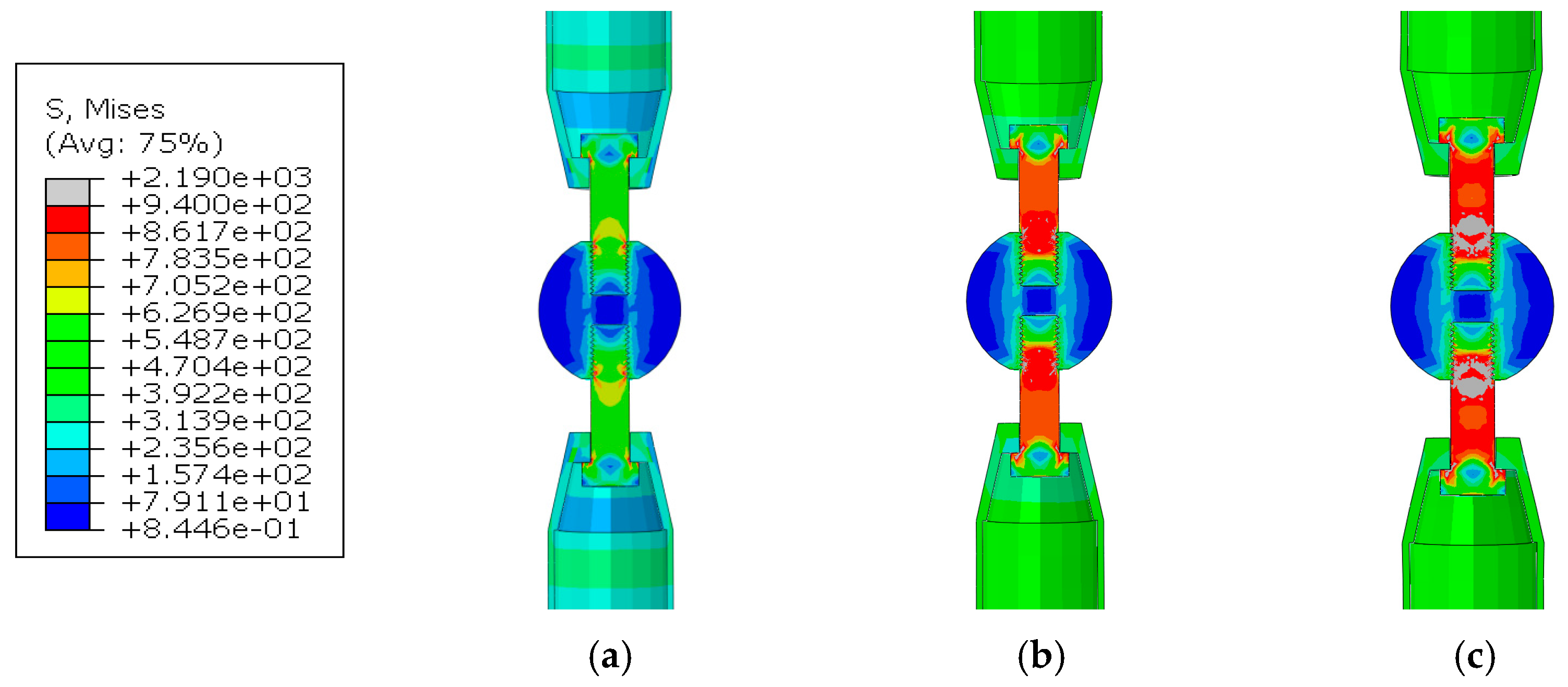
Buildings 12 01989 g017
Figure 18. Stress diagrams of the bolt-sphere joint with members: (a) initial loading; (b) mid-term loading; (c) postloading.
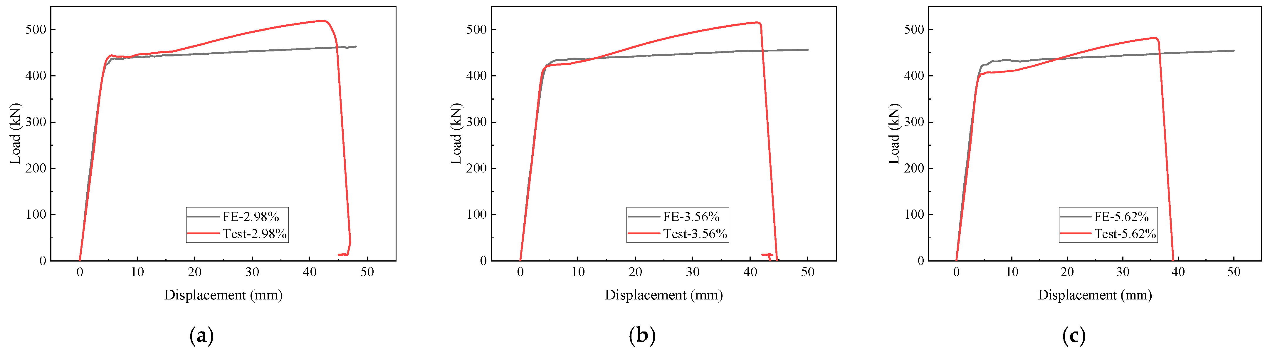
Buildings 12 01989 g018
Figure 19. FE results of the corroded bolt-sphere joints with members: (a) w = 2.98%; (b) w = 3.56%; (c) w = 5.62%.
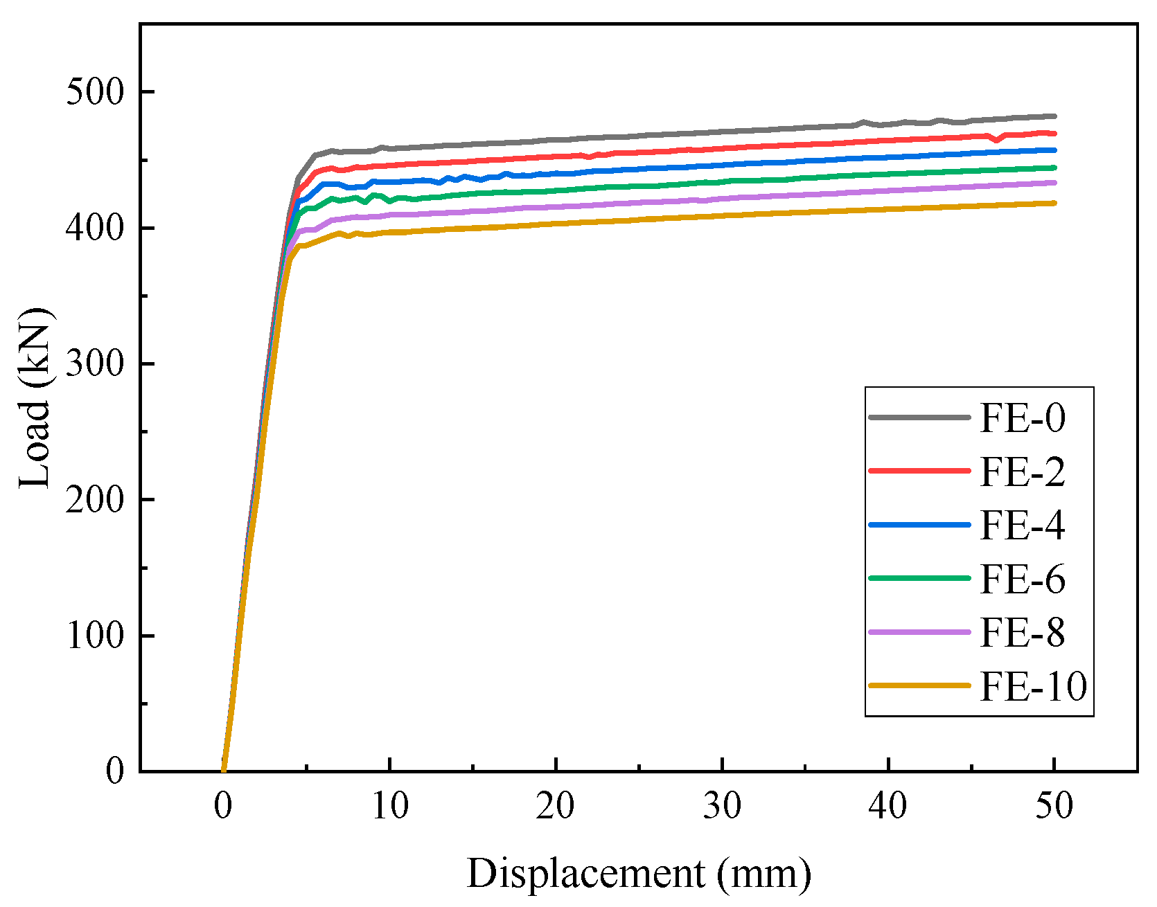
Buildings 12 01989 g019
Figure 20. Load-displacement curves of the corroded bolt-sphere joints with members for different degrees of corrosion.
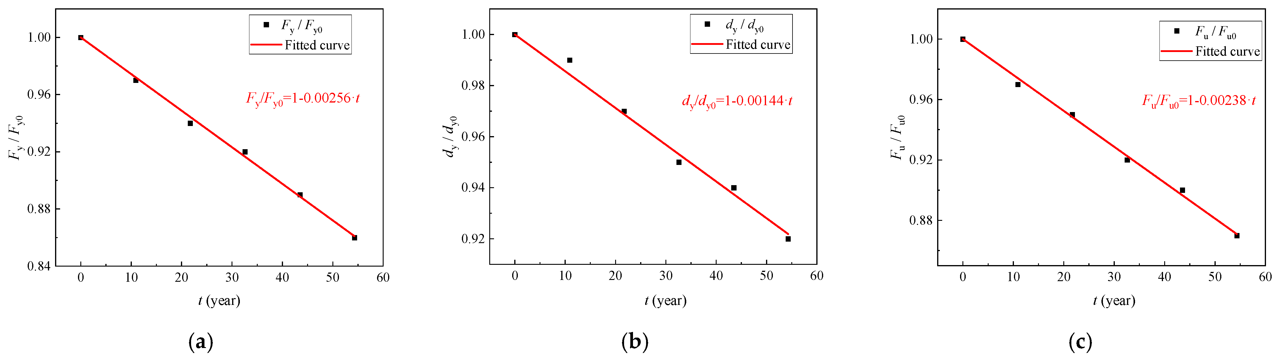
Buildings 12 01989 g020
Figure 21. Fitting results against the service life, t, in years: (a) Fy/Fy0; (b) dy/dy0; (c) Fu/Fu0.
Buildings 12 01989 g021
Table 1. Dimensions of bolt-sphere connections.
Parametersd1d2d3d4d5d6
Value/mm503020254012.5
Table 2. Dimensions of bolt-sphere joints with members.
Parametersd1d2d3d4d5d6d7d8d9
Value/mm5030273555172088.5435
Table 3. Chemical composition of the parts (wt%).
PartsMaterialCSiMnPSCrNiCuAl
Bolt40Cr0.38~0.440.20~0.240.64~0.680.013~0.024≤0.0080.94~0.98
Bolt-Sphere45 Steel0.42~0.50.17~0.370.5~0.8≤0.04≤0.04≤0.25≤0.3≤0.25
MemberQ3550.160.351.340.0090.0020.30.30.30.01~0.05
Table 4. Results of the accelerated corrosion of the bolt-sphere connections.
SpecimensTime/DaysInitial Mass/kgAfter Corrosion/kgMass Loss/kgw/%
C-004.024.0200
C-1154.033.920.112.73
C-2304.023.880.143.48
C-3454.053.870.184.44
Table 5. Results of accelerated corrosion of the bolt-sphere joints with members.
SpecimensTime/DaysInitial Mass/kgAfter Corrosion/kgMass Loss/kgw/%
J-0015.3515.3500
J-11515.4114.950.462.98
J-23015.4414.890.553.56
J-34515.3614.500.865.62
Table 6. Results of the tensile properties of the corroded bolt-sphere connections.
Specimensw/%Fy/kNdy/mmFu/kNdu/mm
C-00225.890.87273.247.26
C-12.73224.010.86272.097.84
C-23.48219.070.84267.537.65
C-34.44216.490.82264.737.52
Table 7. Results of the tensile properties of the corroded bolt-sphere joints with members.
Specimensw/%Fy/kNdy/mmFu/kNdu/mm
J-00455.215.39508.2840.79
J-12.98442.155.22518.6342.17
J-23.56423.714.93515.2741.24
J-35.62407.614.75481.6535.63
Table 8. The corrosion rates of different steels in Beijing.
Corrosive EnvironmentCorrosion Rate/μm/a
Q355B45 Steel40Cr
Atmosphere117.45.7
Table 9. Parameters for the threads.
BoltExternal Diameter/mmInternal Diameter/mmH/mmP/mm
M202017.2942.1652.5
M272723.7522.5983.0
Table 10. Material properties.
PartMaterialE/MPaPoisson’s Ratiofy/MPafu/MPa
Bolt-Sphere45steel210,0000.3355600
Bolt40Cr210,0000.39401150
MemberQ355210,0000.3410550
Table 11. Mechanical parameters of the corroded Q355B.
w (%)E/MPafy/MPafu/MPaεu
0210,0004105900.2
2205,7373995710.193
2.98203,6483935610.189
3.56202,4113905550.187
4201,4743885510.186
5.62198,0213795350.180
6197,2113775320.179
8192,9483655120.172
10188,6853544930.165
Table 12. Comparison of the FE and test results.
w2.98%3.56%5.62%
TestFEDeviation/%TestFEDeviation/%TestFEDeviation/%
Fy442.15430.03−2.74423.71423.48−0.05407.61419.522.92
dy5.225.15−1.344.934.72−4.264.754.49−5.47
Fu518.63458.4−11.61515.27453.65−11.96481.65449.72−6.63
Table 13. Mechanical parameters of the corroded bolt-sphere joints with members.
FE Modelw/%Fy/kNdy/mmFu/kN
FE-00449.795.28482.31
FE-22436.385.22469.94
FE-44422.595.12457.46
FE-66414.244.99444.32
FE-88398.514.97433.32
FE-1010387.074.84418.24
Table 14. Results of normalization analysis on the bolt-sphere joints.
w/%t/yearFy/Fy0dy/dy0Fu/Fu0
00.001.001.001.00
210.90.970.990.97
421.70.940.970.95
632.60.920.950.92
843.50.890.940.90
1054.30.860.920.87
Publisher’s Note: MDPI stays neutral with regard to jurisdictional claims in published maps and institutional affiliations.

