Article

Numerical Modelling of Timber Beams with GFRP Pultruded Reinforcement

by
Satheeskumar Navaratnam
1,
Deighton Widdowfield Small
2,
Marco Corradi
2,
Perampalam Gatheeshgar
3,
Keerthan Poologanathan
2,* and
Craig Higgins
4
1
School of Engineering, RMIT University, Melbourne, VIC 3000, Australia
2
Department of Mechanical and Construction Engineering, Northumbria University, Newcastle upon Tyne NE7 7XA, UK
3
School of Computing, Engineering and Digital Technologies, Teesside University, Middlesbrough TS1 3BX, UK
4
James Christopher Consulting Ltd., Newcastle upon Tyne NE3 1XD, UK
*
Author to whom correspondence should be addressed.
Buildings 2022, 12(11), 1992; https://doi.org/10.3390/buildings12111992
Submission received: 10 September 2022 / Revised: 1 November 2022 / Accepted: 8 November 2022 / Published: 16 November 2022
(This article belongs to the Section Building Energy, Physics, Environment, and Systems)

Abstract

:
Timber structural members have been widely adopted and used in construction due to their inherent characteristics. The main objective of this work is to assess the performance of timber beams with GFRP pultruded beam reinforcement subjected to flexure. A finite element model (FEM) using ABAQUS FEM software is developed, aiming to provide a benchmark modelling procedure. The modelling method considers the fundamental role of the connections among timber beams, the reinforcing GFRP pultruded profile (adhesive and screw connections), and the grain direction in the timber. To understand the influence of the grain direction, different angles of deviations between the longitudinal direction (along the grain) and the beam axis are considered. The robustness of the developed FEM procedure is validated by the experimental results of timber beams with and without GFRP pultruded reinforcement under flexure. It is demonstrated that the angle of deviation (grain deviation) produces high reductions in the strength of unreinforced timber beams. However, this effect is minimal for GFRP-reinforced timber beams. The experimentally derived benchmark FEM procedure can be used as a computational tool for timber beams with GFRP pultruded reinforcement to capture the capacity, failure mode, and load–displacement response.

1. Introduction

Timber beams have been used in construction for thousands of years [1]. There are a number of well-known systems that use timber beams as a basis for horizontal diaphragms in buildings (floors, roofs, etc.), including modular buildings. One-way beam floors are common in historic constructions in many countries: timber floor construction uses timber studs or joists, together with a structural timber board or clay tiles, to form a horizontal structural system that transmits vertical loads to the walls [2]. Figure 1 shows different types of timber beam floors. Timber beam floors are common in several parts of Europe. The structure is a hierarchical system: tiles or boards rest on a timber rafter, and the rafters are supported by timber beams.
The structural purpose of a timber beam floor is to resist the bending moment induced by vertical permanent loads (structural and non-structural dead loads) and live loads applied on the timber boards or tile diaphragms. The static scheme is relatively simple (determinate structure), and it can be described using the analogy of a simply supported beam under a uniform distributed load. However, there are several uncertainties to consider: the fact that timber is a natural material, its non-isotropic structure, the effect of moisture content, defects such as knots and grain deviation, and cracking and splitting resulting from differential shrinkage during the seasoning process [3,4]. Building codes have typically considered all these uncertainties by using high safety factors for all mechanical properties to use in design. In addition, the moisture content and biotic attacks from insects and fungi have been addressed in many standards by introducing the exposure coefficient [5].
Because timber is one of the oldest construction materials, a very large number of heritage and historic constructions are made with timber floors. In Italy, 62% of buildings constructed before 1910 have timber beam floors. A similar situation likely applies in many other countries [6]. Because timber is lightweight, cheap, abundant in nature, easy to work with and transport and, most importantly, has high tensile strength, it has been used where tensile and bending loads have to be resisted. For horizontal diaphragms in historic constructions, the only possible alternative was iron beams or vaulted masonry structures, but the economic costs were much higher.
The static loads considered in the past in design were markedly smaller. Furthermore, modern building codes require significantly higher safety factors compared to the ones used in the pre-industrial period. In this situation, structural engineers can opt for the replacement or reinforcement of existing timber beam floors. Replacing timber floors with reinforced concrete (RC) has been commonly used in the second half of the 20th century in many European countries [7]. However, recent seismic events [8,9,10] have clearly demonstrated its weakening effect.
Conventional methods of reinforcing structural timber have used steel, iron, RC, or aluminium plates that are bonded to the tension surface of timber beams [11,12,13,14]. Since the year 2000, the use of composite materials (fibre-reinforced polymers (FRPs)) has been investigated; epoxy or polyurethane resins have been proposed to bond plates or fill grooves cut in beams to install composite bars (typically carbon (CFRP) or glass (GFRP)) [15,16,17,18]. These traditional methods have drawbacks, such as problems of corrosion (for iron and steel reinforcements), increased dead loads (for RC) or limited improvement in the bending capacity (for timber and aluminium).
FRP unidirectional or bidirectional sheets have been investigated by several researchers, with positive results in terms of an improvement in capacity. However, there are three main limitations: (1) FRP sheet reinforcement is unable to increase the bending stiffness of beams (the small quantity of fibre reinforcement and its orientation produce very small increments in the second moment of the reinforced beam cross-section); (2) the level of reversibility is low (according to ICOMOS, interventions on heritage structures should be reversible in order to allow future reinforcements using new methods); (3) the impact in terms of aesthetics is significant (FRP sheets are bonded on the tension side of the timber beams) [19,20,21].
Considering that many timber beam floors need to be reinforced because of problems of excessive vibrations or bending deformations, and many are listed by conservation bodies, which do not typically authorize interventions using composites bonded with resins, it is evident that these limitations are particularly difficult to overcome.
Usually, bending reinforcements are applied at the beam tension side, but this has a significant impact on the aesthetics of the timber structure, especially when reinforcements are mounted near the surface. The tension side of timber beams in floors and roof structures is typically left in view, and FRP sheets, plates, and strips are perceived as ugly by the general public, especially when used in buildings with cultural and architectural value. The opposite compression side is often hidden from view, under the tiles of the floor or other types of walking surfaces.
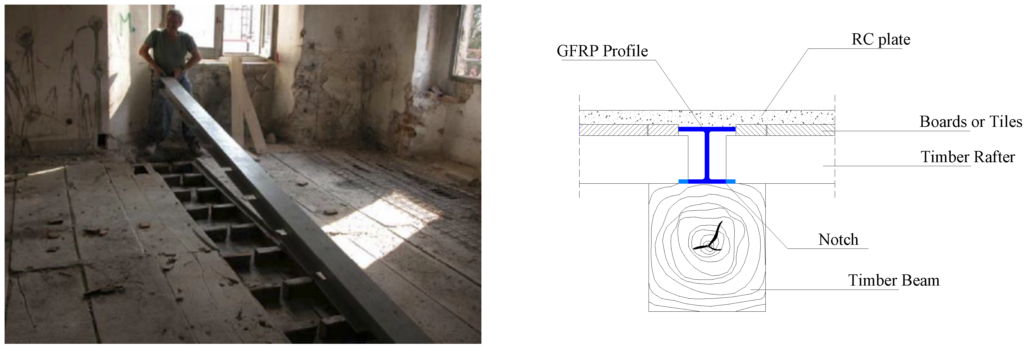
The solution proposed in this research is to use GFRP pultruded profiles to be connected to the beam compression side using screws or metal fasteners (Figure 2). This solution could solve the limitations listed above. GFRP pultruded profiles have been used to produce hybrid elements with traditional materials (i.e., steel, timber, and concrete) due to their numerous advantages compared to traditional materials, such as a high strength-to-weight ratio, low self-weight, low maintenance requirements, and improved durability under aggressive environments [22,23,24,25,26]. An experimental campaign was conducted, and a numerical procedure is proposed in this paper for design purposes. The compression side of timber beams is often hidden from view. GFRP profiles can be applied over the beams or under the tiles of the floor and other types of walking surfaces. This facilitates the application of GFRP profiles, which are much lighter than steel beams and easy to cut, if necessary, onsite.
The flexural strength and stiffness of the proposed composite timber GFRP pultruded beam have been investigated through experimental tests [27]. The strength performance of these reinforced composites is dependent on the strength of the timber, GFRP pultruded beam, screws, and epoxy adhesive. The strength of the timber beam is depending on the fibre orientation and angle of deviation between the fibre orientation and beam axis [28,29,30]. Thus, the influence of the timber strength on the flexural strength and stiffness of the proposed composite timber GFRP pultruded beam needs to be investigated. This study proposes an orthotopic elasto-plastic numerical model to predict the timber strength and the strength, stiffness, and failure modes of a timber beam reinforced with a GFRP pultruded beam.

Existing Numerical Modelling Method for Timber

Timber, because it is a natural material, has a high coefficient of variation [31]. The orthotropic properties of timber have been studied, and it is known that the strength of timber is highly dependent on the grain direction. The strength and stiffness of timber are typically the highest along the longitudinal axis (i.e., parallel to the grain). Meanwhile, they are lower in the radial (i.e., normal to the growth rings, which is perpendicular to the grain) and the tangential (perpendicular to the grain but tangential to the growth rings) directions. Green et al. [32] found that the mechanical properties of timber can be affected by both the manufacturing process and service environments. Thus, the modelling of timber is more complex, and most of the structural design models assume timber is an orthotopic material to simplify the model. Navaratnam et al. [31,33,34] and Shekarchi [35] implemented simplified assumptions in their numerical model and determined a strong correlation between the model of timber and real-world application. Navaratnam et al. [31] proposed a numerical modelling technique to assess the bending performance of cross-laminated timber (CLT). The numerical modelling properties were validated against the experimental results and showed similar failure modes to the experimental tests. The similarity of the results showed that the modelling method created is suitable to predict failure. Consequently, similar methods can be also used to model timber reinforced with GFRP pultruded profiles.
A 3D finite element model (FEM) of composite structures can sufficiently evaluate the inelastic behaviour of steel and concrete [36,37,38,39]. However, when considering the non-linear and anisotropic behaviour of timber, failure modes are not readily available. Failure criteria such as those in the works of Tsai-Wu [40] and Hashin [41,42,43,44,45] are commonly used to develop composite elements, which can be used to model a GFRP pultruded beam. Hill’s [46] anisotropic plasticity-based model has been used to varying levels of success in the FEM of timber. Tsai-Wu [40] approximated the actual behaviour of orthotropic composites such as timber, and the elliptical failure envelope modelled adequately captured the biaxial stress states of wood species [47].
Hill’s yield criterion [8] has been used to define the plastic behaviour of anisotropic materials such as timber. Guan and Zhu [10] developed a method to model the anisotropic elasto-plastic behaviour of composite timber beams using ABAQUS [48]. Plasticity-based models account for the hardening and densification of timber and have been employed to analyse timber joints with dowel connections [29,49]. However, the presence of defects from the manufacturing process and the brittle nature of timber under tension and shear have decreased the accuracy of the FEMs of plasticity-based models [49]. Navaratnam et al. [31,33] used Hill’s constants (F, G, H, L, M, and N) to determine the failure mode of CLT in a composite structure. From this method, a strong correlation was found between the experimental and FEM analysis. This illustrates that this method can be used to accurately model the structural behaviour of timber in composite structures. Oudjene and Khelifa [29] determined a constitutive law defining the behaviour of wood as elasto-plastic. This model was also successfully validated in ABAQUS [48] using Hill’s criterion.
Valipour et al. [50] proposed a constitutive law to capture the deflection response and failure mode of Douglas Fir timber. In this model, the timber itself was defined as a composite material due to its anisotropic nature. The proposed modelling technique proposed was compared with experimental data [30]. The results show a strong correlation between the ultimate loading capacity of the experimental tests and the FEM. Therefore, the comparative analysis showed that the simple modelling technique developed can be used to accurately determine the load–displacement response, the ultimate loading capacity, and the failure modes of timber composite elements. FEM analysis was also used to structurally detail a multi-surface plasticity model for clear wood. However, it tended to overestimate the tensile strength of timber [47].
Previous studies have demonstrated that several constitutive law and numerical model techniques exist to predict the load capacity of timber beams. However, limited knowledge is available on the flexural performance of timber beams reinforced with GFRP pultruded beams. Thus, this study proposes an elasto-plastic constitutive law to predict the strength of timber beams reinforced with GFRP pultruded beams.

2. Experimental Method

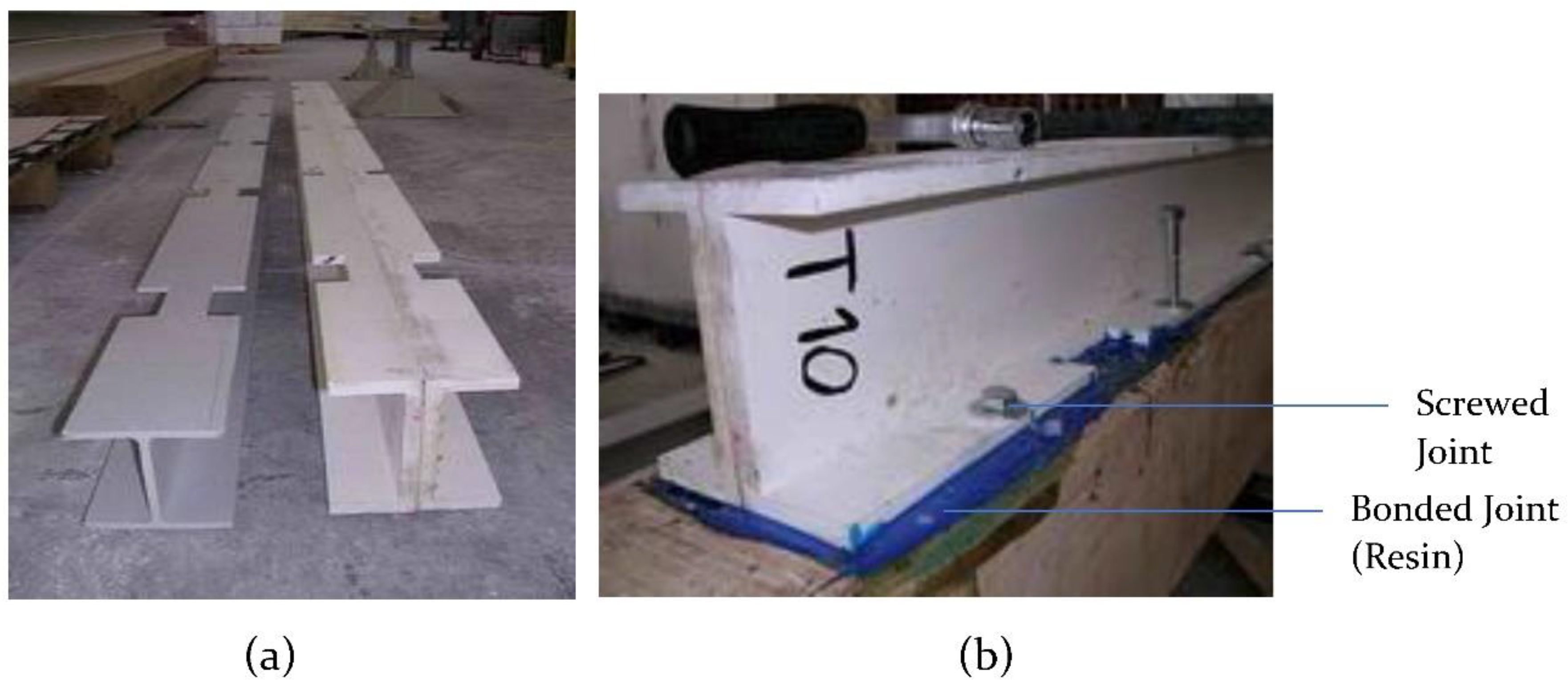
Twelve full-size, solid timber beams (7 firwood (A-series) and 5 chestnut (C-series)) were tested in flexure. The beam dimensions were 180 × 180 × 3050 mm, and the moisture content was 11.4%. The weight densities were 452 kg/m3 and 800 kg/m3 for the firwood and chestnut, respectively. The timber beams were reinforced using two types (letter designations: H and I) of 2500 mm GFRP pultruded profiles. The nominal dimensions of the H type were 101 mm (height), 100 mm (width), 7 mm (flange and web thickness). The I types were made out of 2 C-shaped pultruded profiles, epoxy-bonded together, with dimensions of 137 mm (height), 120 mm (width, 60 mm for the single C-shaped profile), 12 mm (flange thickness), and 24 mm (web thickness) (Figure 3). Unfortunately, not all types of GFRP sections were available on the construction market; this is the reason the I-type reinforcement system was made out of 2 C-shaped sections bonded together.
Before application, the GFRP profiles were notched with a spacing of 500 mm. This was necessary to simulate, in a real-case scenario, the constraint of the timber rafters (Figure 4). The dimensions of the notches were 80 × 30 mm. Notching is relatively simple, and it can be done on-site. Initially, 3 mm diameter holes were drilled at the vertices of the rectangular-shaped notch, and an electric angle grinder and a hand hacksaw frame were subsequently used to remove the GFRP material. More details of the experimental method are reported in [27].
The joints between the timber beams and the GFRP profiles were made using an epoxy resin (bonded joint) and 10 mm diameter metal screws with a spacing of 250 mm (Figure 5). After the resin had cured (72 h), screws were installed to strengthen the GFRP profiles. Thus, the beams acted compositely with the load transferred between them by a combination of shear stresses (parallel to the joint) and peel stresses (normal to the joint).
Table 1 reports the test results in terms of the maximum bending load Pmax, the secant stiffness at the maximum load (ku), and the secant stiffness k1/3, calculated as 1/3 of Pmax. This table also gives the increments compared to unreinforced beams (two in firwood, A1 and A4, and 2 in chestnut wood, C1 and C4). It can be noted that the installation of a GFRP profile at the compression side caused a good improvement in the load capacity (varying between −1% and 107% for I-type profiles, and between 107% and 240% for H-type). However, this retrofitting solution is particularly interesting for increasing the bending stiffness, increasing it up to 374%, making this intervention particularly suitable for old timber beam floors where excessive vibrations and deflections are often a problem. The analysis of the failure mode also highlights that the levels of the bending load were very low (about 20% Pmax), the bonded joint started cracking, and the connection between the beams and the profiles was only guaranteed by the metal screws. The bonded joint was too stiff and ultimately unable to transfer the stresses from the timber to the GFRP. It can be concluded that the bonded joint can be avoided, also facilitating the reversibility of the intervention. The failure was always initiated by the timber cracking at the beam tension side.
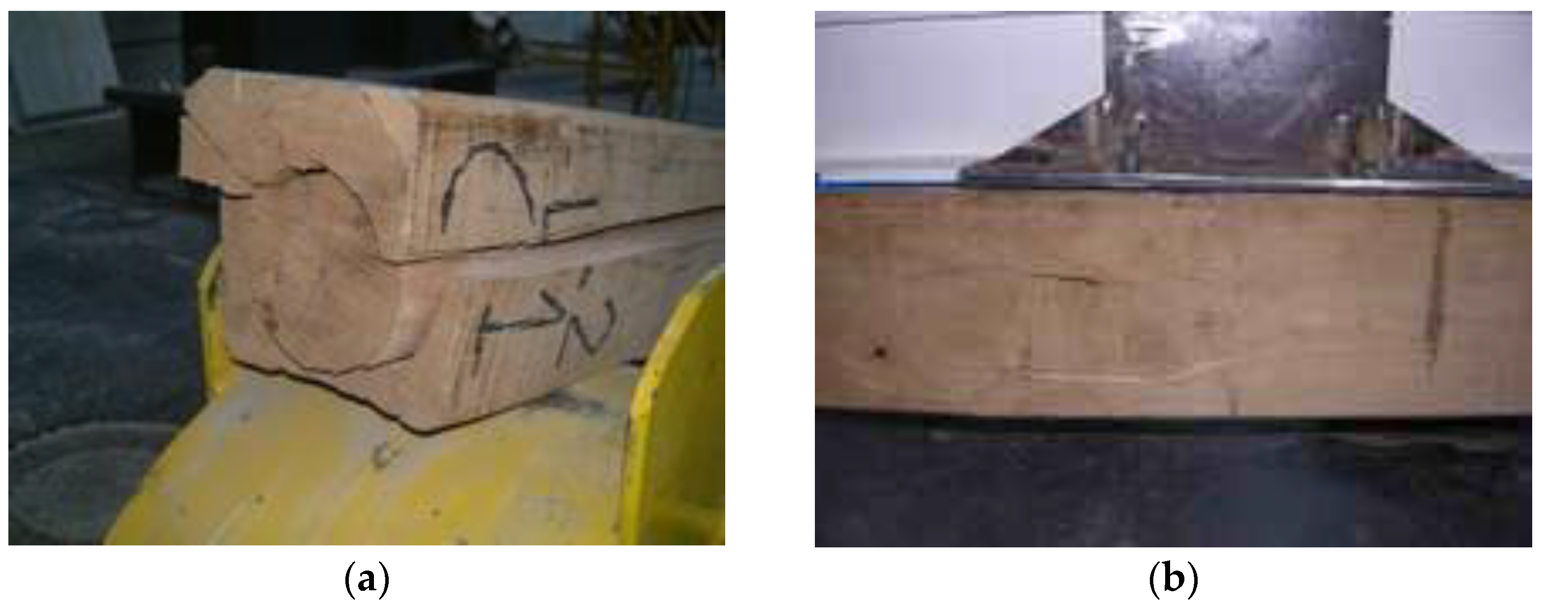
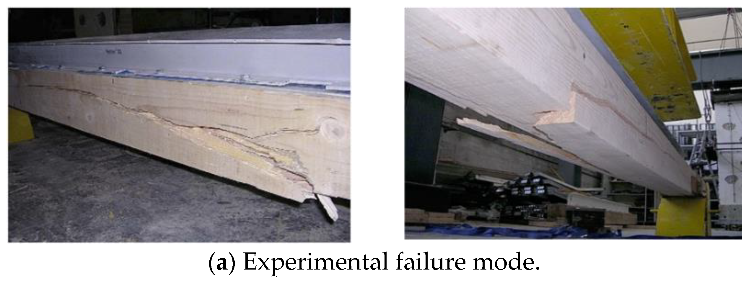
The failure modes of both the unreinforced and reinforced timber beams were similar. Cracking occurred along the grain in the timber on the tension side, where the bending moment was at the maximum (Figure 6). This crack was initiated at a point around the mid-span of the beam, and it propagated toward the beam ends when increasing the bending load. This crack was the reason for the progressive reduction of the beam capacity. Further, when large bending deformation was reached, the GFRP profile also started cracking around the notched area.

3. FEM Development

The FEM of the GFRP pultruded reinforced timber beam was developed using ABAQUS [48] finite element software. This model consists of three independent parts, which are a white fir timber beam, a GFRP pultruded beam, and 4.8-type [51] steel screws and steel plate (used for loading and support) (Figure 7). The model was validated against the experimental tests by Corradi and Borri [27]. The displacement-controlled load was applied in the FEM. Based on the experimental tests, pin and roller support boundary conditions were applied in the FE model at the bottom of the support steel plate. This steel plate was modelled using an eight-node hexahedral brick element (C3D8R) with isotropic elastic material properties (i.e., Young’s modulus of 2.1 GPa and Poisson’s ratio of 0.3).

3.1. FEM of Timber

3.1.1. Theoretical Formulation

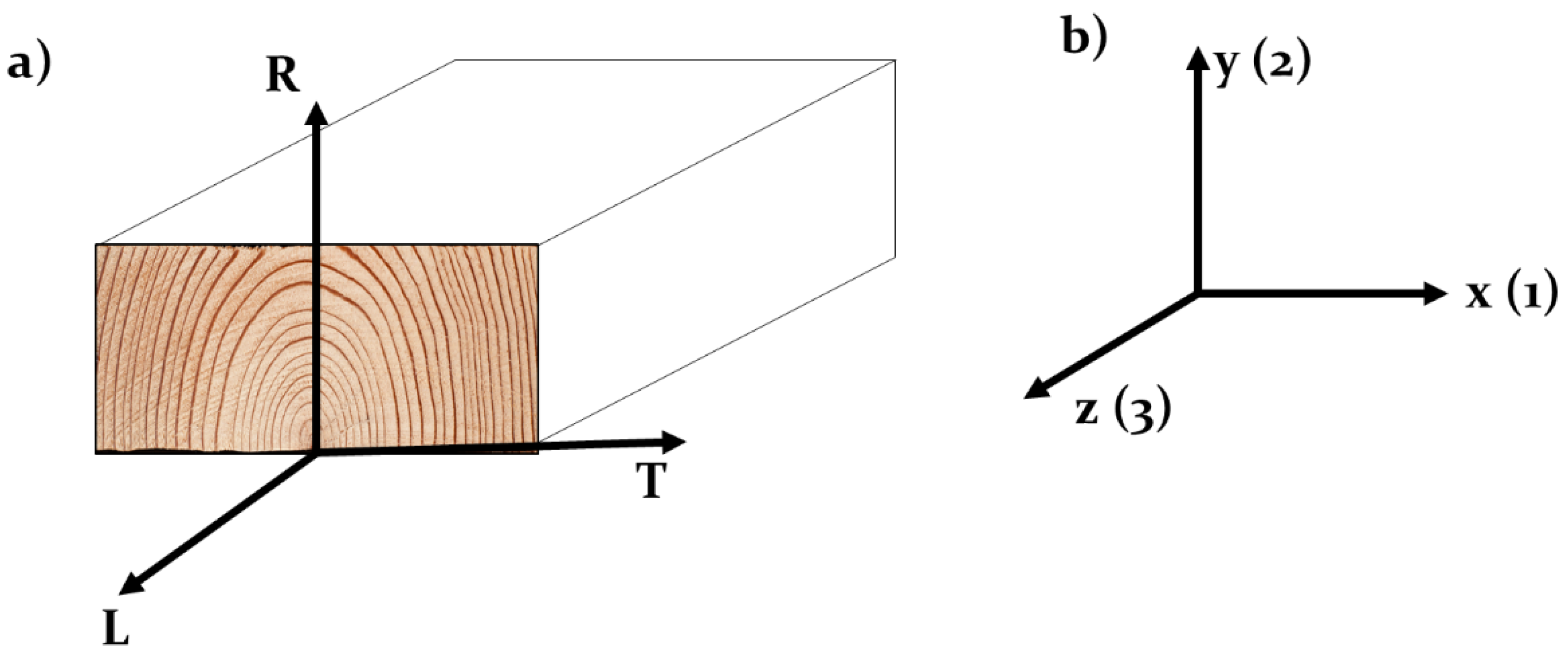
Timber is a natural material and the measurements of the strength of timber have a wide range. Timber is generally considered an orthotopic material. The material properties of timber are described based on the grain orientation in three directions, which are the longitudinal (L), radial®, and tangential (T) directions (Figure 8).
The timber orthotopic elastic properties can be defined by Equation (1) using linear elastic stresses and strains:
[ σ ¯ ] = [ A ] [ ε ¯ ]
where [ σ ¯ ] , [A], and [ ε ¯ ] are the stress tensor, martial matrix, and strain tensor. The material matrix [A] is determined by the compliance matrix ([B]) of the material properties based on the local coordination.
[ A ] = [ B ] 1
[ B ] = [ 1 E L v R L E R v T L E T 0 0 0 v L R E L 1 E R v T R E T 0 0 0 v L T E L v R T E R 1 E T 0 0 0 0 0 0 1 G L R 0 0 0 0 0 0 1 G L T 0 0 0 0 0 0 1 G R T ]
EL, ET, and ER are the elastic properties; GLR, GLT, and GRT are the shear moduli in the respective orthotropic planes, and vLR, vLT, vRL, vRT, vTL, and vTR are the Poisson’s ratios in the respective orthotropic planes. To satisfy the material stability, the following requirement should be achieved [48]:
E L , E T , E R , G L R , G L T   and   G R T > 0 | v L R | < ( E L E R ) 1 / 2 | v L T | < ( E L E T ) 1 / 2 | v R T | < ( E R E T ) 1 / 2 1 v L R v R L v R T v T R v T L v L T 2 v R L v T R v L T > 0 }
[ σ ¯ ] = [ σ L σ R σ T τ L R τ L T τ R T ] T
[ ε ¯ ] = [ ε L ε R ε T γ L R γ L T γ R T ] T
The strength and stiffness of timber are typically high along the grain and low in the other two directions (perpendicular to the grain). The parallel-to-grain direction in timber beams generally matches the beam axial direction. However, there could be a deviation between the beam axial direction and the direction parallel to the grain, which have a significant influence on the strength and stiffness of a timber beam. To represent this deviation in the numerical model, a transformation matrix [M] was introduced to the stress [σ] and strain [ε]. This [M] is formed with the angle of grain deviation between the local and global coordination [28].
[ ε ] = [ M ]   [ ε ¯ ]
[ σ ] = [ M ] T [ σ ¯ ]
[ M ] = [ α L x α L x α L y α L y α L z α L z α L x α L y α L z α L x α L y α L z α R x α R x α R y α R y α R z α R z α R x α R y α R z α R x α R y α R z α T x α T x α T y α T y α T z α T z α T x α T y α T x α T y α T y α T z 2 α L x α R x 2 α L y α R y 2 α L z α R z α L x α R y + α L y α R x α L z α R x + α L x α R z α L y α R z + α L z α R y 2 α T x α L x 2 α T y α L y 2 α T z α L z α T x α L y + α T y α L x α T z α L x + α T x α L z α T y α L z + α T z α L y 2 α R x α T x 2 α R y α T y 2 α R z α T z α R x α T y + α R y α T x α R z α T x + α R x α T z α R y α T z + α R z α T y ]
where the α is the cosine for the grain deviation angle, and the superscripts (x, y, z) and subscripts (L, R, T) denote the local and global axes, respectively.
The anisotropic plastic behaviour of timber can be modelled using the rectangular Cartesian stress components defined by Hill [46]. A similar method has been used by Navaratnam et al. [31,33], Guan and Zhu [52], and Oudjene and Khelifa [29]. Hill’s yield criteria are expressed as:
f ( σ ) = F ( σ R R σ T T ) 2 + G ( σ T T σ L L ) 2 + H ( σ L L σ R R ) 2 + 2 L σ R T 2 + 2 M σ T L 2 + 2 N σ L R 2
F, G, H, L, M, and N are Hill’s constants that were obtained from the experimental tests of the timber in different orientations, which are defined as:
F = ( σ 0 ) 2 2 ( 1 σ ¯ R R 2 + 1 σ ¯ T T 2 1 σ ¯ L L 2 ) = 1 2 ( 1 R 22 2 + 1 R 33 2 1 R 11 2 )
G = ( σ 0 ) 2 2 ( 1 σ ¯ T T 2 + 1 σ ¯ L L 2 1 σ ¯ R R 2 ) = 1 2 ( 1 R 33 2 + 1 R 11 2 1 R 22 2 )
H = ( σ 0 ) 2 2 ( 1 σ ¯ L L 2 + 1 σ ¯ R R 2 1 σ ¯ T T 2 ) = 1 2 ( 1 R 11 2 + 1 R 22 2 1 R 33 2 )
L = 3 2 ( τ 0 σ ¯ R T ) 2 = 3 2 R 23 2
M = 3 2 ( τ 0 σ ¯ L T ) 2 = 3 2 R 13 2
N = 3 2 ( τ 0 σ ¯ L R ) 2 = 3 2 R 12 2
where the measured σ ¯ i j is the component yield stress to the reference yield stress σ0 of timber. R11, R22, R33, R12, R23 and R13 are the anisotropic yield stress ratios, which can be obtained from Equation (16).
R 11 = σ ¯ L L σ 0 , R 22 = σ ¯ R R σ 0 , R 11 = σ ¯ T T σ 0 R 12 = σ ¯ L R τ 0 , R 13 = σ ¯ L T τ 0 , R 23 = σ ¯ R T τ 0 }
τ 0 = σ 0 3
The orthotopic associate flow rule is expressed as:
d [ ε ] p l = d λ f σ = d λ f [ J ]
[ J ] = [ G ( σ T T σ L L ) + H ( σ L L σ R R ) F ( σ R R σ T T ) + H ( σ L L σ R R ) F ( σ R R σ T T ) + G ( σ T T σ L L ) 2 N σ L R 2 M σ T L 2 L σ R T ]
where λ is the plastic multiplier.

3.1.2. Model Implementation for Fir Timber Beam

Table 1 shows the material properties of timber used to calculate all the components defined in Equation (1) to Equation (19). The FEM was developed using ABAQUS [48] finite element software. In this model development, the following assumptions were made to simplify the FEM. The first assumption is that the material properties of timber (Table 2) are not affected by the moisture or environmental temperature variations. The timber profiles are assumed to be free of defects. The material hardening and toughening is not accounted in this model. A similar approach was used to model the anisotropic elasto-plastic timber composite beams by Guan and Zhu [52]. The eight-node hexahedral brick element (C3D8R) listed in the ABAQUS [48] element library was used to model the timber beam. To identify the suitable mesh size, this study conducted convergence studies and defined the mesh size as 10 mm × 10 mm.

3.2. FEM of GFRP Pultruded Beam

The GFRP pultruded beam was modelled using the methods suggested by Fernandes et al. [53] and Nunes et al. [54]. A shell element with four-node reduced integration (S4R) was used to create the GFRP pultruded profile. In the convergence study, a mesh size of 5 mm × 5 mm was identified as the most suitable mesh to simulate the flexural behaviour of a GFRP pultruded beam. The strength and elastic properties used in the model were obtained in the experimental tests and literature reviews [27,53,54,55,56,57] and are detailed in Table 3. The failure criterion was employed through the Hashin damage criteria specified in ABAQUS [48]. The fracture energy associate with each failure mode is shown in Table 3.

3.3. Contact and Interaction Definition

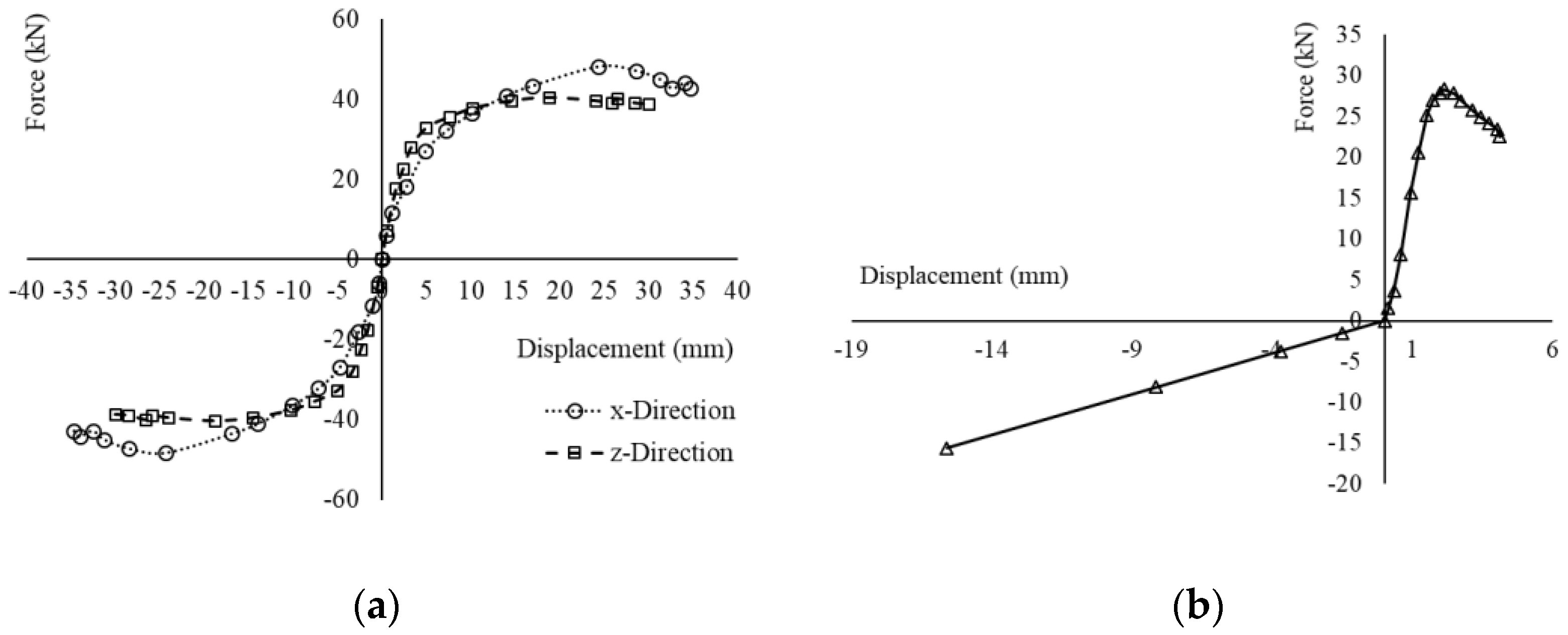
The surface interactions between the steel and timber and the GFRP and timber were modelled using penalty friction contact defined in the ABAQUS [48]. Friction coefficients of 0.3 and 0.5 were set for the surfaces between the steel and timber and the GFRP and timber in the tangential direction. Hard contact was defined in the normal direction of both interactions. The GFRP pultruded beam and fir timber beam were connected with 4.8-type steel screws (10 mm in diameter and 80 mm in length) and epoxy resin. The screws were replaced with three non-linear spring elements per screw. Each spring element was activated in the x, y, and z directions. The force–displacement relationship of these spring elements is defined in the literature [58,59,60,61] (Figure 9). A surface-to-surface cohesive contact was used to replace the epoxy resin bond between the timber and the GFRP. The tensile strength, compressive strength, and Young’s modulus of the epoxy resin were 23.43 MPa, 56.54 MPa, and 2112 MPa [27], respectively. The cohesive properties of epoxy resin were obtained from previous experimental studies [27,31,62,63,64]. The normal and shear stiffness (Knn, Kss, and Ktt) of the epoxy was assumed to be equal (528 N/mm3), and the fracture energy (Gf) was taken as 0.92 N/mm.

4. Results and Discussion

FEM Validation

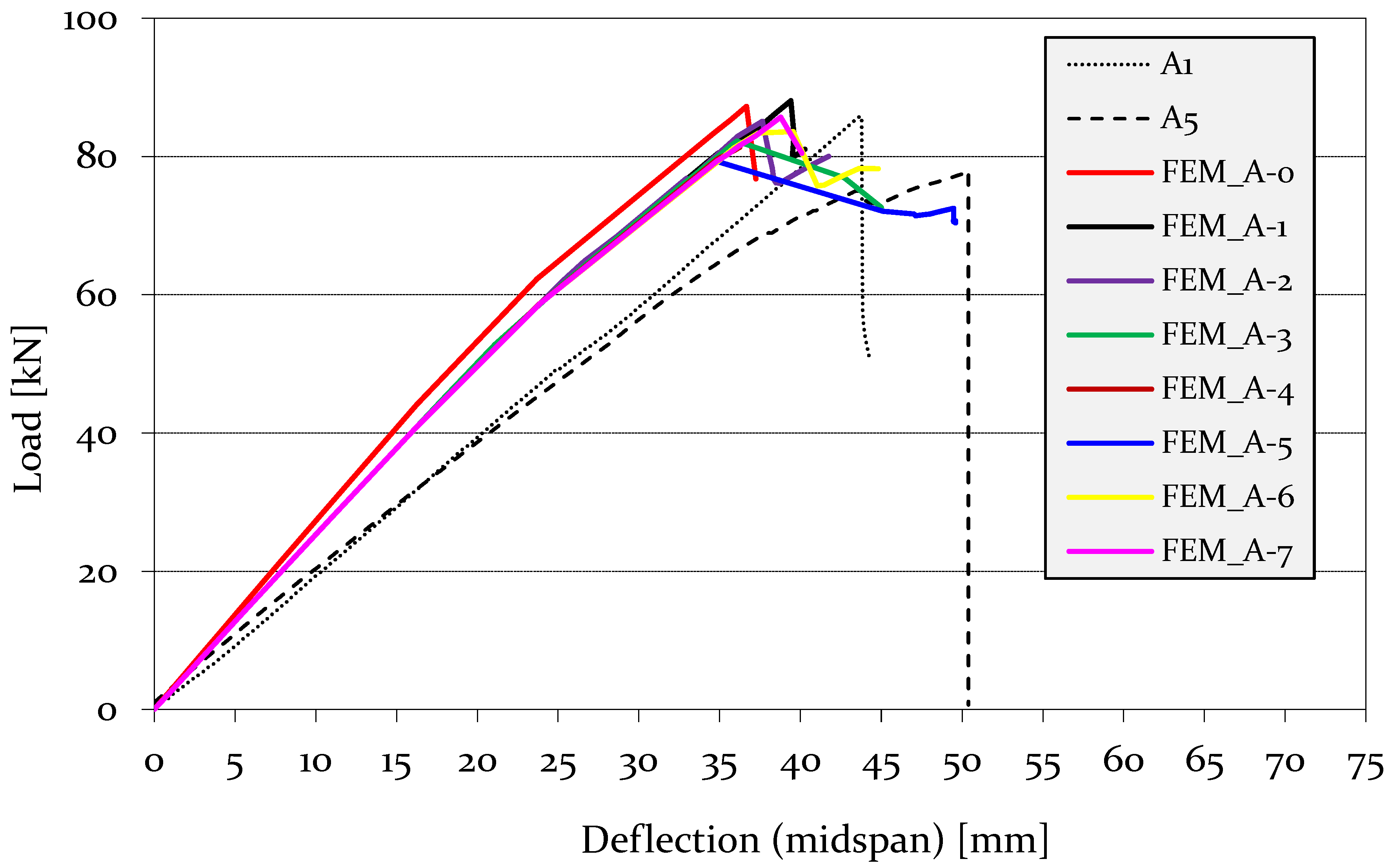
A comparison of the FE modelling results with the experimental results is discussed herein, emphasizing the flexural strength, load–displacement response, and failure modes. For the validation, bare white fir timber beams (A1, A5), and white fir timber beams with H-type GFRP pultruded reinforcement (A3 + H3, A4 + H2) were selected according to Corradi and Borri [27]. During the experiments, it was noticed that some of the timber beams had grain deviation (i.e., 1°–7°) between the fibre direction and the beam axis. Therefore, this study developed eight FEMs that also considered the angle of grain deviation ( α L z ) between the local (L) and global (z) axes. Table 4 illustrates the types of FEMs developed in this study.
The failure load values for both the experimental and FEM results are presented in Table 5 for unreinforced timber beams A1 and A5. The FEM results demonstrate that the grain deviation had a certain degree of influence on the bending capacity of the unreinforced timber beams. For grain deviations of 0° to 7° the test/FEM ratios varied from 0.93 to 1.03. The failure load predictions for both the experimental and FEM results for the reinforced timber beams A3 + H3 and A4 + H2 are reported in Table 6. In contrast, the FEM results show that the influence of the grain deviation on the bending capacity of the timber beam reinforced with GFRP was minimal compared to the variation noticed in the unreinforced timber beam.
A comparison of the force–displacement relationship between the FEM and experimental tests of the unreinforced timber beam is illustrated in Figure 10. From the results, it can be noticed that the FEM was able to reasonably capture the stiffness of the unreinforced beam. In observing the FEM force–displacement curves with and without including the grain deviation in the FEM analysis, it can be concluded that a grain deviation of 0° resulted in slightly higher initial stiffness compared to a grain deviation of 1°–7°. Moreover, FEMs with a grain deviation of 1°–7° produced an identical initial stiffness. However, there were some differences in structural behaviour after reaching the peak load.
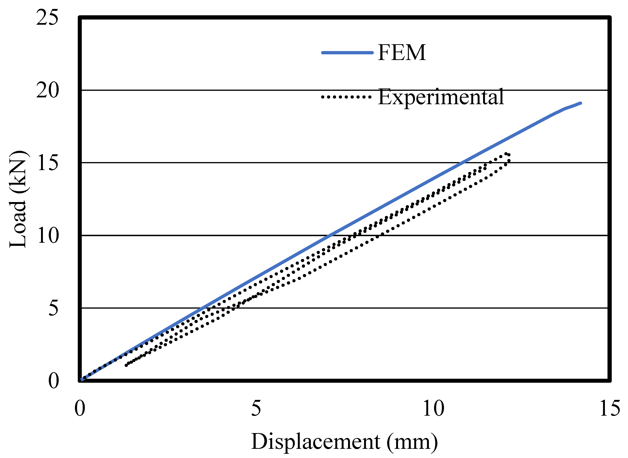
A comparison of the experiment and FEM of the elastic test results of the GFRP pultruded profile is depicted in Figure 11. It can be noticed that there was good agreement between the experimental and FEM stiffness, given by the slope of the lines in the bending load–deflection plot.
A comparison of the bending load–displacement relationship between the FEM and experimental tests of the timber beams reinforced with pultruded GFRP is depicted in Figure 12. It can be observed that the FEM was able to capture the stiffness of the GFRP-reinforced timber beam. This shows the capability of the developed FEMs. Unlike the unreinforced timber beams, there were no variations in the initial stiffness between the FEM force–displacement curves when the angle of grain deviation was taken into account and when it was not. This is due to the fact that the GFRP-reinforced timber beam acted in a composite manner and reduced the material scattering in the timber.
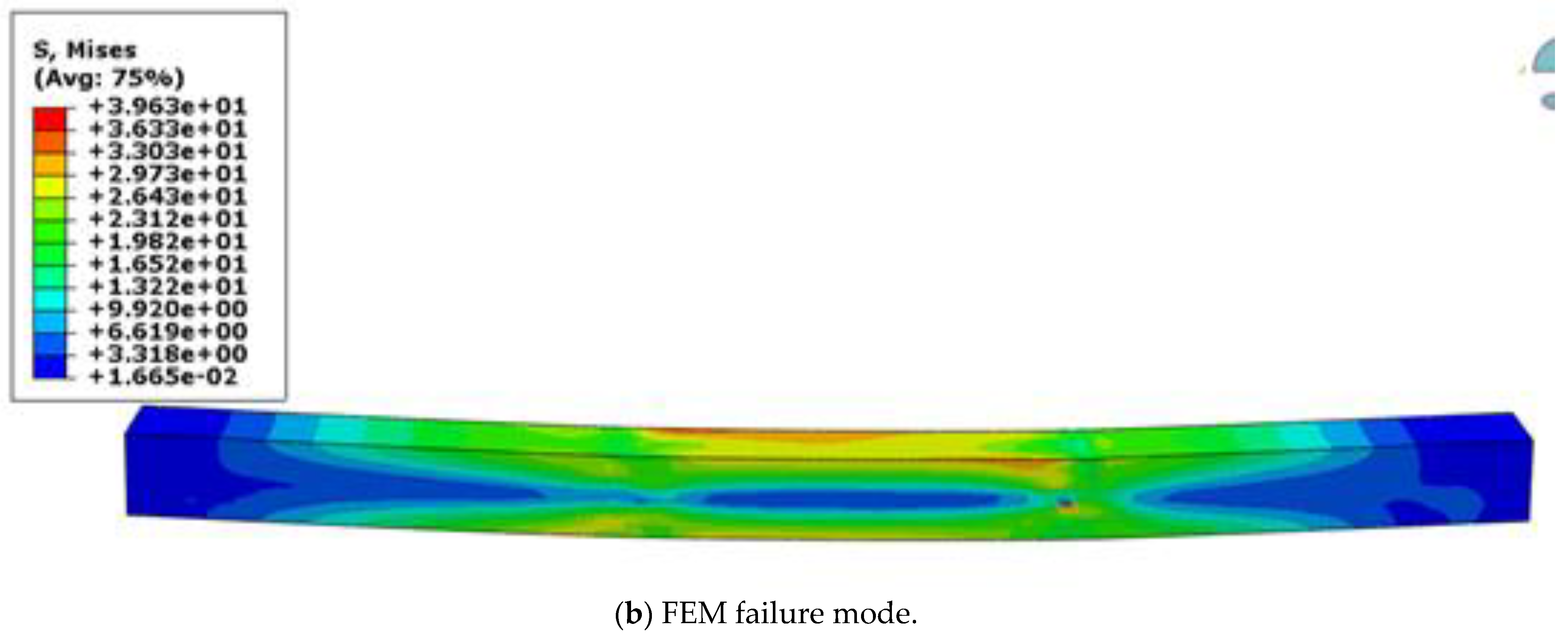
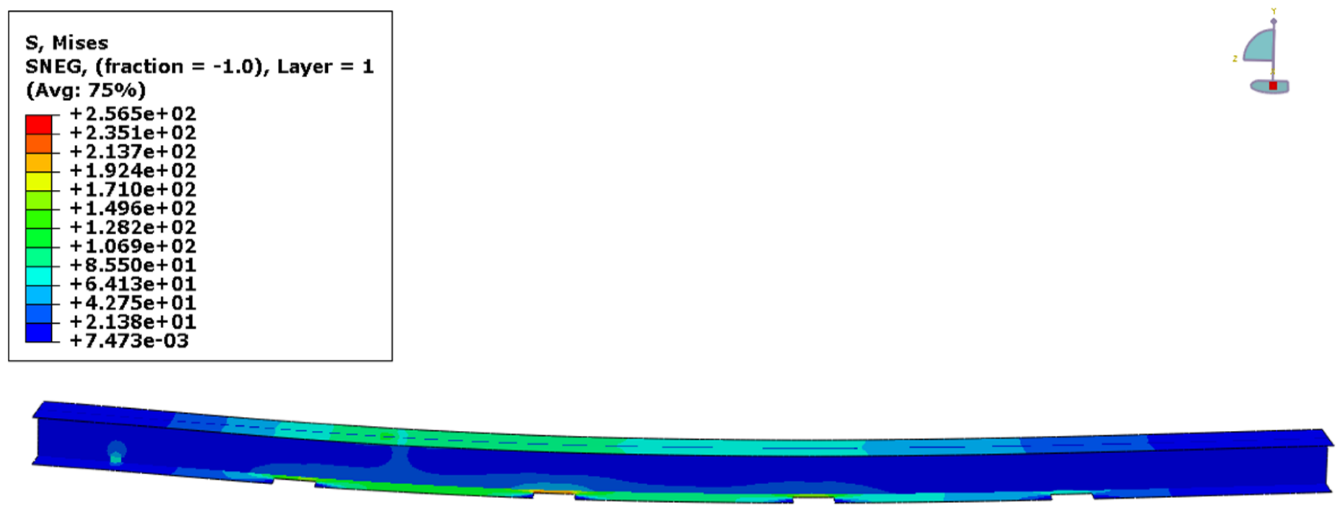
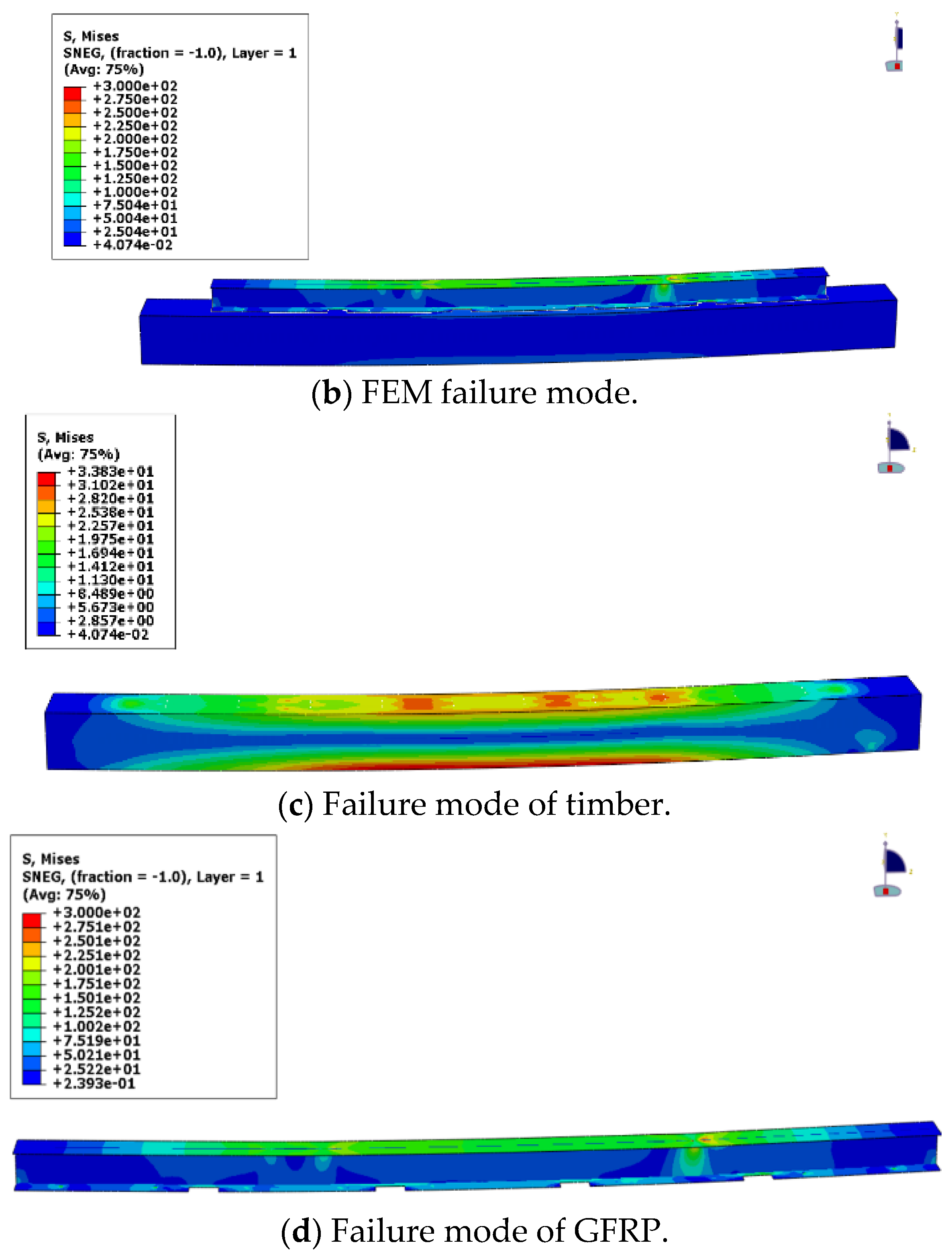
The failure modes in the FEMs were also compared with the experimental ones. Figure 13 compares the test and FEM failure modes for an unreinforced timber beam. Flexural tensile rupture was noticed in the experiments, and the FEM also yielded similar failure, as noticed from the von Mises stress distribution. The failure mode of the GFRP pultruded profile subject to flexure is presented in Figure 14. The comparison of the failure modes is shown in Figure 15. There was a clear tensile failure mode in the experiment, and a similar failure mode can also be observed in the FEMs based on the von Mises stress distribution.

5. Conclusions

This paper presents a benchmark finite element modelling procedure that can accurately simulate the flexural response of timber beams with GFRP pultruded reinforcement. The developed finite element modelling procedure includes the connection between timber beams and reinforcing GFRP pultruded profiles (adhesive and screw connections). The model also considers the grain deviation in timber. The proposed modelling procedure was verified against the experimental results available in the literature. The impact and conclusions of this work are useful in timber research and practical applications:
  • The FEM introduced was able to capture flexural strength, load–displacement response, and complex failure modes very similar to those in the experimental results.
  • The key point in the modelling procedure is the connection between the timber beam and the GFRP pultruded profiles. The good agreement with the experimental results shows that the proposed spring-based modelling for screws can mobilise the composite action within the system.
  • The influence of the grain deviation was also studied by considering different mode angles in the models. The results demonstrate that the grain deviation influenced the flexural strength of timber beams without GFRP pultruded reinforcement.
  • It was noticed that there was a lesser effect of the grain deviation on the flexural strength of timber beams with GFRP pultruded reinforcement.

Author Contributions

Conceptualization, S.N., M.C. and K.P.; methodology, S.N. and M.C.; software, S.N.; validation, S.N., M.C. and K.P.; formal analysis, S.N., D.W.S. and M.C.; investigation, S.N., D.W.S. and M.C.; resources, S.N., K.P. and M.C.; data curation, S.N., D.W.S., M.C., K.P. and P.G.; writing—original draft preparation, S.N., D.W.S., M.C. and P.G.; writing—review and editing, S.N., D.W.S., M.C., K.P., C.H. and P.G.; visualization, S.N., D.W.S. and M.C.; supervision, M.C. and K.P.; project administration, K.P.; funding acquisition, K.P. All authors have read and agreed to the published version of the manuscript.

Funding

This research received no external funding.

Institutional Review Board Statement

Not applicable.

Informed Consent Statement

Not applicable.

Data Availability Statement

Not applicable.

Acknowledgments

This work was supported by RMIT University, Northumbria University, and Teesside University in terms of technical and financial support and research facilities.

Conflicts of Interest

The authors declare there are no conflict of interest in this research.

Nomenclature

EYoung’s modulus
F, G, H, L, M, NHill’s constants
GLR, GLT, GRTShear modulus
Gft, Gfc, Gmt, GmcFracture energy
R11, R22, R33, R12, R23, R13Anisotropic yield stress ratios
vPoisson’s ratio
x (1), y (2), z (3)Global coordination
ft,0°Tensile strength parallel to grain
fc,0°Compressive strength parallel to grain
ft,90°Tensile strength perpendicular to grain
fc,90°Compressive strength perpendicular to the fibre direction
fτShear strength
[M]Transformation matrix
[ ε ¯ ] Strain tensor
ε ¯ Strains in the local coordinate system
εStrain
[ σ ¯ ] Stress tensor
σ 0 Reference yield stress
σ ¯ Stresses in the local coordinate system
σNormal stress
σc,90°Yield stress under compression in the perpendicular direction
αCosine for the grain deviation angle
τShear stress
γShear strain
λPlastic multiplier
Subscripts
cCompressive
fFibre
tTensile
mMatrix
LLongitudinal direction (parallel to grain)
RRadial direction (perpendicular to grain)
TTangential direction (perpendicular to grain)
Abbreviations
CFRPCarbon fibre-reinforced polymer
FEMFinite element model
FRPFibre-reinforced polymer
GFRPGlass fibre-reinforced polymer
RCReinforced concrete

References

  1. Thomas, H.; Julius, N.; Roland, S.; Michael, V.; Wolfgang, W. Timber Construction Manual; Birkhäuser: Basel, Switzerland, 2012. [Google Scholar]
  2. Historic England. Practical Building Conservation: Timber; Routledge: London, UK, 2012. [Google Scholar]
  3. Ross, P. Appraisal and Repair of Timber Structures; Thomas Telford: London, UK, 2002. [Google Scholar]
  4. Satheeskumar, N. Wind Load Sharing and Vertical Load Transfer from Roof to Wall in a Timber-Framed House. Ph.D. Thesis, James Cook University, Douglas, Australia, 2016. [Google Scholar]
  5. European Committee for Standardization. Eurocode 5: Design of Timber Structures; European Committee for Standardization (CEN): Brussels, Belgium, 2004. [Google Scholar]
  6. Istat, 15° Censimento Generale Della Popolazione e Delle Abitazioni 15th Census of Population and Constructions in Italy, 2011. Available online: https://www.istat.it/it/censimenti-permanenti/censimenti-precedenti/popolazione-e-abitazioni/popolazione-2011 (accessed on 1 November 2022).
  7. Borri, A.; Corradi, M. Architectural Heritage: A Discussion on Conservation and Safety. Heritage 2019, 2, 631–647. [Google Scholar] [CrossRef] [Green Version]
  8. Atalić, J.; Uroš, M.; Novak, M.Š.; Demšić, M.; Nastev, M. The Mw5.4 Zagreb (Croatia) earthquake of March 22, 2020: Impacts and response. Bull. Earthq. Eng. 2021, 19, 3461–3489. [Google Scholar] [CrossRef] [PubMed]
  9. Arslan, M.H.; Korkmaz, H.H.; Gulay, F.G. Damage and failure pattern of prefabricated structures after major earthquakes in Turkey and shortfalls of the Turkish Earthquake code. Eng. Fail. Anal. 2006, 13, 537–557. [Google Scholar] [CrossRef]
  10. Macabuag, J.; Altheim, C.; Thorvaldsdottir, S.; Perks, D. Damage assessments by International Engineers following the Albania earthquake of November 2019. Int. J. Disaster Risk Reduct. 2022, 72, 102822. [Google Scholar] [CrossRef]
  11. Jasieńko, J.; Nowak, T.P. Solid timber beams strengthened with steel plates—Experimental studies. Constr. Build. Mater. 2014, 63, 81–88. [Google Scholar] [CrossRef]
  12. Franke, S.; Franke, B.; Harte, A.M. Failure modes and reinforcement techniques for timber beams—State of the art. Constr. Build. Mater. 2015, 97, 2–13. [Google Scholar] [CrossRef]
  13. Corradi, M.; Osofero, A.I.; Borri, A. Repair and Reinforcement of Historic Timber Structures with Stainless Steel—A Review. Metals 2019, 9, 106. [Google Scholar] [CrossRef] [Green Version]
  14. Pavković, K.; Stepinac, M.; Rajčić, V. Brittle failure modes in reinforced and non-reinforced timber joint with large diameter fastener loaded parallel to grain. Eng. Struct. 2020, 222, 111104. [Google Scholar] [CrossRef]
  15. Alam, P.; Ansell, M.P.; Smedley, D. Mechanical repair of timber beams fractured in flexure using bonded-in reinforcements. Compos. Part B Eng. 2009, 40, 95–106. [Google Scholar] [CrossRef]
  16. Raftery, G.M.; Harte, A.M. Low-grade glued laminated timber reinforced with FRP plate. Compos. Part B Eng. 2011, 42, 724–735. [Google Scholar] [CrossRef]
  17. ICOMOS–ISCARSAH Committee. ICOMOS Charter—Principles for the analysis, conservation and structural restoration of architectural heritage. In Proceedings of the ICOMOS 14th General Assembly and Scientific Symposium, Victoria Falls, Zimbabwe, 27–31 October 2003; Volume 2731. [Google Scholar]
  18. Francesco, M.; Scialpi, V.; Tegola, A.L. Flexural Reinforcement of Glulam Timber Beams and Joints with Carbon Fiber-Reinforced Polymer Rods. J. Compos. Constr. 2005, 9, 337–347. [Google Scholar]
  19. Gilfillan, J.R.; Gilbert, S.G.; Patrick, G.R.H. The Use of FRP Composites in Enhancing the Structural Behavior of Timber Beams. J. Reinf. Plast. Compos. 2003, 22, 1373–1388. [Google Scholar] [CrossRef]
  20. Fiorelli, J.; Dias, A.A. Glulam beams reinforced with FRP externally-bonded: Theoretical and experimental evaluation. Mater. Struct. 2011, 44, 1431–1440. [Google Scholar] [CrossRef]
  21. Vahedian, A.; Shrestha, R.; Crews, K. Experimental and analytical investigation on CFRP strengthened glulam laminated timber beams: Full-scale experiments. Compos. Part B Eng. 2019, 164, 377–389. [Google Scholar] [CrossRef]
  22. Vedernikov, A.; Gemi, L.; Madenci, E.; Özkılıç, Y.O.; Yazman, Ş.; Gusev, S.; Sulimov, A.; Bondareva, J.; Evlashin, S.; Konev, S.; et al. Effects of high pulling speeds on mechanical properties and morphology of pultruded GFRP composite flat laminates. Compos. Struct. 2022, 301, 116216. [Google Scholar] [CrossRef]
  23. Correia, J.R.; Cabral-Fonseca, S.; Branco, F.A.; Ferreira, J.G.; Eusébio, M.I.; Rodrigues, M.P. Durability of pultruded glass-fiber-reinforced polyester profiles for structural applications. Mech. Compos. Mater. 2006, 42, 325–338. [Google Scholar] [CrossRef]
  24. Correia, J.R.; Branco, F.A.; Ferreira, J.G. Flexural behaviour of GFRP–concrete hybrid beams with interconnection slip. Compos. Struct. 2007, 77, 66–78. [Google Scholar] [CrossRef]
  25. Gemi, L.; Madenci, E.; Özkılıç, Y.O.; Yazman, Ş.; Safonov, A. Effect of Fiber Wrapping on Bending Behavior of Reinforced Concrete Filled Pultruded GFRP Composite Hybrid Beams. Polymers 2022, 14, 3740. [Google Scholar] [CrossRef]
  26. Lokuge, W.; Otoom, O.; Borzou, R.; Navaratnam, S.; Herath, N.; Thambiratnam, D. Experimental and numerical analysis on the effectiveness of GFRP wrapping system on timber pile rehabilitation. Case Stud. Constr. Mater. 2021, 15, e00552. [Google Scholar] [CrossRef]
  27. Corradi, M.; Borri, A. Fir and chestnut timber beams reinforced with GFRP pultruded elements. Compos. Part B Eng. 2007, 38, 172–181. [Google Scholar] [CrossRef]
  28. Ormarsson, S. Numerical Analysis of Moisture-Related Distortions in Sawn Timber. Ph.D. Thesis, Chalmers University of Technology, Gothenburg, Sweden, 1999. [Google Scholar]
  29. Oudjene, M.; Khelifa, M. Elasto-plastic constitutive law for wood behaviour under compressive loadings. Constr. Build. Mater. 2009, 23, 3359–3366. [Google Scholar] [CrossRef]
  30. Kim, Y.J.; Harries, K.A. Modeling of timber beams strengthened with various CFRP composites. Eng. Struct. 2010, 32, 3225–3234. [Google Scholar] [CrossRef]
  31. Navaratnam, S.; Small, D.W.; Gatheeshgar, P.; Poologanathan, K.; Thamboo, J.; Higgins, C.; Mendis, P. Development of cross laminated timber-cold-formed steel composite beam for floor system to sustainable modular building construction. Structures 2021, 32, 681–690. [Google Scholar] [CrossRef]
  32. Green, D.W.; Winandy, J.E.; Kretschmann, D.E. Mechanical properties of wood. In Wood Handbook: Wood as an Engineering Material; USDA Forest Service, Forest Products Laboratory: Madison, WI, USA, 1999; p. 4. [Google Scholar]
  33. Navaratnam, S.; Herath, N.; Lokuge, W.; Thamboo, J.; Poologanathan, K. Performance of timber girders with end-notch: Experimental and numerical investigation. Structures 2021, 29, 730–740. [Google Scholar] [CrossRef]
  34. Satheeskumar, N.; Henderson, D.J.; Ginger, J.D.; Wang, C.H. Finite element modelling of the structural response of roof to wall framing connections in timber-framed houses. Eng. Struct. 2017, 134, 25–36. [Google Scholar] [CrossRef]
  35. Shekarchi, M.; Oskouei, A.V.; Raftery, G.M. Flexural behavior of timber beams strengthened with pultruded glass fiber reinforced polymer profiles. Compos. Struct. 2020, 241, 112062. [Google Scholar] [CrossRef]
  36. Korkmaz, H.H.; Dere, Y.; Özkılıç, Y.O.; Bozkurt, M.B.; Ecemiş, A.S.; Özdoner, N. Excessive snow induced steel roof failures in Turkey. Eng. Fail. Anal. 2022, 141, 106661. [Google Scholar] [CrossRef]
  37. Gatheeshgar, P.; Poologanathan, K.; Thamboo, J.; Roy, K.; Rossi, B.; Molkens, T.; Perera, D.; Navaratnam, S. On the fire behaviour of modular floors designed with optimised cold-formed steel joists. Structures 2021, 30, 1071–1085. [Google Scholar] [CrossRef]
  38. Navaratnam, S.; Thamboo, J.; Poologanathan, K.; Roy, K.; Gatheeshgar, P. Finite element modelling of timber infilled steel tubular short columns under axial compression. Structures 2021, 30, 910–924. [Google Scholar] [CrossRef]
  39. Ishqy, M.F.M.; Wanniarachchi, S.; Poologanathan, K.; Gunalan, S.; Gatheeshgar, P.; Suntharalingam, T.; Navaratnam, S. Shear behaviour of cold-formed stainless-steel beams with web openings: Numerical studies. Structures 2021, 31, 127–144. [Google Scholar] [CrossRef]
  40. Tsai, S.W.; Wu, E.M. A General Theory of Strength for Anisotropic Materials. J. Compos. Mater. 1971, 5, 58–80. [Google Scholar] [CrossRef]
  41. Hashin, Z. Failure Criteria for Unidirectional Fiber Composites. J. Appl. Mech. 1980, 47, 329–334. [Google Scholar] [CrossRef]
  42. Klasztorny, M.; Bondyra, A.; Szurgott, P.; Nycz, D. Numerical modelling of GFRP laminates with MSC.Marc system and experimental validation. Comput. Mater. Sci. 2012, 64, 151–156. [Google Scholar] [CrossRef]
  43. Gupta, A.K.; Velmurugan, R.; Joshi, M. Numerical and experimental study of multimode failure phenomena in GFRP laminates of different lay-ups. Int. J. Crashworthiness 2018, 23, 87–99. [Google Scholar] [CrossRef]
  44. Czechowski, L.; Gliszczyński, A.; Bieniaś, J.; Jakubczak, P.; Majerski, K. Failure of GFRP channel section beams subjected to bending-Numerical and experimental investigations. Compos. Part B Eng. 2017, 111, 112–123. [Google Scholar] [CrossRef]
  45. Ulger, T.; Okeil, A.M. Analysis of thin-walled steel beams retrofitted by bonding GFRP stiffeners: Numerical model and investigation of design parameters. Eng. Struct. 2017, 153, 166–179. [Google Scholar] [CrossRef]
  46. Hill, R.; Orowan, E. A theory of the yielding and plastic flow of anisotropic metals. Proc. R. Soc. Lond. Ser. A Math. Phys. Sci. 1948, 193, 281–297. [Google Scholar]
  47. Mackenzie-Helnwein, P.; Eberhardsteiner, J.; Mang, H.A. A multi-surface plasticity model for clear wood and its application to the finite element analysis of structural details. Comput. Mech. 2003, 31, 204–218. [Google Scholar] [CrossRef]
  48. ABAQUS. Theory Manual, Version 6.14; Hibbitt, Karlsson & Sorensen, Inc.: Providence, RI, USA, 2014. [Google Scholar]
  49. Nouri, F.; Valipour, H.R.; Bradford, M.A. Finite element modelling of steel-timber composite beam-to-column joints with nominally pinned connections. Eng. Struct. 2019, 201, 109854. [Google Scholar] [CrossRef]
  50. Valipour, H.; Khorsandnia, N.; Crews, K.; Foster, S. A simple strategy for constitutive modelling of timber. Constr. Build. Mater. 2014, 53, 138–148. [Google Scholar] [CrossRef]
  51. BS EN ISO 898-1:2013; Mechanical Properties of Fasteners Made of Carbon Steel and Alloy Steel Bolts, Screws and Studs with Specified Property Classes. Coarse Thread and Fine Pitch Thread. European Committee for Standardization (CEN): Brussels, Belgium, 2013.
  52. Guan, Z.W.; Zhu, E.C. Finite element modelling of anisotropic elasto-plastic timber composite beams with openings. Eng. Struct. 2009, 31, 394–403. [Google Scholar] [CrossRef]
  53. Fernandes, L.A.; Nunes, F.; Silvestre, N.; Correia, J.R.; Gonilha, J. Web-crippling of GFRP pultruded profiles. Part 2: Numerical analysis and design. Compos. Struct. 2015, 120, 578–590. [Google Scholar] [CrossRef]
  54. Nunes, F.; Correia, J.R.; Silvestre, N. Structural behavior of hybrid FRP pultruded beams: Experimental, numerical and analytical studies. Thin-Walled Struct. 2016, 106, 201–217. [Google Scholar] [CrossRef]
  55. Fascetti, A.; Feo, L.; Nisticò, N.; Penna, R. Web-flange behavior of pultruded GFRP I-beams: A lattice model for the interpretation of experimental results. Compos. Part B Eng. 2016, 100, 257–269. [Google Scholar] [CrossRef]
  56. Madenci, E.; Özkılıç, Y.O.; Gemi, L. Experimental and theoretical investigation on flexure performance of pultruded GFRP composite beams with damage analyses. Compos. Struct. 2020, 242, 112162. [Google Scholar] [CrossRef]
  57. Alhawamdeh, M.; Alajarmeh, O.; Aravinthan, T.; Shelley, T.; Schubel, P.; Kemp, M.; Zeng, X. Modelling hollow pultruded FRP profiles under axial compression: Local buckling and progressive failure. Compos. Struct. 2021, 262, 113650. [Google Scholar] [CrossRef]
  58. Asiz, A.; Smith, I. Connection System of Massive Timber Elements Used in Horizontal Slabs of Hybrid Tall Buildings. J. Struct. Eng. 2011, 137, 1390–1393. [Google Scholar] [CrossRef]
  59. Ellingsbø, P.; Malo, K. Withdrawal capacity of long self-tapping screws paralell to grain direction. In Proceedings of the World Conference on Timber Engineering, WCTE 2012, Auckland, New Zealand, 15–19 July 2012; pp. 228–237. [Google Scholar]
  60. Maik, G. Pull-Out Resistance of Self-Tapping Wood Screws with Continuous Thread. Ph.D. Thesis, The University of British Columbia, Vancouver, BC, Canada, 2011. [Google Scholar]
  61. Hassanieh, A.; Valipour, H.R.; Bradford, M.A. Experimental and analytical behaviour of steel-timber composite connections. Constr. Build. Mater. 2016, 118, 63–75. [Google Scholar] [CrossRef]
  62. Masood, S.N.; Viswamurthy, S.R.; Singh, A.K.; Muthukumar, M.; Gaddikeri, K.M. Simulation and validation of disbond growth in co-cured composite skin–stringer specimens using cohesive elements. J. Compos. Mater. 2017, 52, 807–822. [Google Scholar] [CrossRef]
  63. Ikramullah; Afrizal, A.; Huzni, S.; Thalib, S.; Abdul Khalil, H.P.S.; Rizal, S. Effect of Mesh Sensitivity and Cohesive Properties on Simulation of Typha Fiber/Epoxy Microbond Test. Computation 2020, 8, 2. [Google Scholar] [CrossRef] [Green Version]
  64. Liu, C.; Zhou, Z.; Wang, X.; Zhang, B. Analysis and determination for the parameters of “cohesive element” in the numerical model of single fiber composites: The elastic parameters. J. Reinf. Plast. Compos. 2012, 31, 1127–1135. [Google Scholar] [CrossRef]
Figure 1. (a) Tiles, rafters, and beams; (b) timber beams and boards; (c) decorated timber beam floor: tiles, and two layers of rafters and beams.
Buildings 12 01992 g001
Figure 2. The use of GFRP I- or H-type beams applied at the compression side of timber beams.
Buildings 12 01992 g002
Figure 3. (a) H- and I-type GFRP profiles; (b) different joint methods used for GFRP application.
Buildings 12 01992 g003
Figure 4. Notching procedure of the GFRP profiles.
Buildings 12 01992 g004
Figure 5. Test layout.
Buildings 12 01992 g005
Figure 6. Failure modes: (a) unreinforced timber beam; (b) reinforced beam.
Buildings 12 01992 g006
Figure 7. FEM of a timber beam reinforced with a pultruded profile.
Buildings 12 01992 g007
Figure 8. Timber material directions: (a) local coordination; (b) global coordination.
Buildings 12 01992 g008
Figure 9. Load–displacement relationship for the screwed connection: (a) x and z direction; (b) y direction (−ve is upward and +ve is pull-out direction).
Buildings 12 01992 g009
Figure 10. Comparison of bending load–displacement relationship between FEM and experimental test of unreinforced timber beam.
Buildings 12 01992 g010
Figure 11. Comparison of bending load–displacement relationship between FEM and experimental test of GFRP pultruded beam [27].
Buildings 12 01992 g011
Figure 12. Comparison of bending load–displacement relationship between FEM and experimental tests.
Buildings 12 01992 g012
Figure 13. Comparison of failure modes between FEM and experimental test of unreinforced timber beam (stress values are in MPa).
Buildings 12 01992 g013aBuildings 12 01992 g013b
Figure 14. Failure mode of the bare GFRP pultruded profile subject to flexure from FEM (stress values are in MPa).
Buildings 12 01992 g014
Figure 15. Failure mode comparison of the GFRP-reinforced timber beam (stress values are in MPa).
Buildings 12 01992 g015aBuildings 12 01992 g015b
Table 1. Test results.
No.Pmax
(kN)
Increment Pmax
Reinforced/
Un-Reinforced
k1/3
(N mm−1)
Increment k1/3
Reinforced/
Un-Reinforced
ku
(N mm−1)
Increment ku
Reinforced/
Un-Reinforced
C165.1-1753-1491-
C467.2-1829-1470-
C3 + I1225.23.4075914.2470114.74
C2 + I2183.52.7756653.1658373.94
C5 + H4137.22.0736592.0431022.10
C6 + H5101.81.5431901.7818161.23
A185.8-1975-1971-
A578.0-1988-1547-
A3 + H3173.22.1136991.8731871.81
A2 + H180.80.9923931.2123071.31
A4 + H2148.31.8139441.9922841.30
A6 + I3193.02.3667213.3965353.72
A7 + I4205.82.5168273.4566473.78
Table 2. Material properties of timber [27,30] used in the FEM.
Weight density (kg/m3)452
Young’s modulus L direction (MPa)11,426
Young’s modulus R direction (MPa)888
Young’s modulus T direction (MPa)622
Poisson’s ratio LR0.053
Poisson’s ratio RT0.43
Poisson’s ratio LT0.036
Shear modulus LR (MPa)616
Shear modulus RT (MPa)61.6
Shear modulus LT (MPa)616
σc,90° (MPa)9.6
F0.98
G0.04
H0.02
L = M0.6
N0.9
Table 3. Elastic and strength properties and fracture energy of GFRP.
Modulus of elasticity (E1)36,000 MPa
Modulus of elasticity (E2)5100 MPa
Shear modulus (G12)3000 MPa
Shear modulus (G13)3000 MPa
Shear modulus (G23)190 MPa
Poisson’s Ratio0.28
Tensile strength (ft,0°)402 MPa
Tensile strength (ft,90°)39 MPa
Compressive strength (fc,0°)389 MPa
Compressive strength (fc,90°)101 MPa
Shear strength (fτ)26 MPa
Fracture energy (Gft)12.5 N/mm
Fracture energy (Gfc)12.5 N/mm
Fracture energy (Gmt)1 N/mm
Fracture energy (Gmc)1 N/mm
Note: c, t, f, and m denote the compressive, tensile, fibre, and matrix, respectively.
Table 4. FEM details.
FEM Type α L z Details
FEM_A-0
FEM_A-1
FEM_A-2
FEM_A-3Unreinforced timber
FEM_A-4
FEM_A-5
FEM_A-6
FEM_A-7
FEM_A-0-H
FEM_A-1-H
FEM_A-2-H
FEM_A-3-HReinforced timber
FEM_A-4-H
FEM_A-5-H
FEM_A-6-H
FEM_A-7-H
GFRP GFRP pultruded beam
Table 5. Comparison of the test results with FEM predictions with different grain deviation angles for unreinforced timber beams.
FEM TypeExp-(kN)FEM (kN)Test */FEMk1/3 (N mm−1)ku (N mm−1)
A185.8 19751971
A578 19881547
FEM_A-0 87.30.9427252380
FEM_A-1 88.10.9325282235
FEM_A-2 85.10.9625292261
FEM_A-3 82.31.0025292280
FEM_A-4 81.41.0125292245
FEM_A-5 79.31.0325292276
FEM_A-6 83.60.9825292114
FEM_A-7 85.70.9625292210
* Average test value of A1 and A5.
Table 6. Comparison of the test results with FEM predictions with different grain deviation angles for reinforced timber beam with GFRP H-type profiles.
FEM TypeExp. (kN)FEM (kN)Test */FEMk1/3 (N mm−1)ku (N mm−1)
A3 + H3173.2 36993187
A4 + H2148.3 39442284
FEM_A-0-H 141.61.1443534182
FEM_A-1-H 141.61.1443534114
FEM_A-2-H 145.81.1043504183
FEM_A-3-H 142.11.1343534172
FEM_A-4-H 1481.0943534183
FEM_A-5-H 142.11.1343414172
FEM_A-6-H 146.51.1043544197
FEM_A-7-H 141.81.1343544153
* Average test value of A3 + H3 and A4 + H2.
Publisher’s Note: MDPI stays neutral with regard to jurisdictional claims in published maps and institutional affiliations.