Abstract
For the quick and accurate determination of the cable force under the hybrid boundary between the ear plate and the anchor plate, this paper proposes a method for identifying the boundary conditions and bending stiffness of the cables based on the frequency method. First, the influence of the parameters, namely, cable boundary conditions, bending stiffness, inclination angle, and linear density, on the cable force was analyzed. Next, the actual bending stiffness of the cable under the boundary conditions of the upper hinged support and the lower solid support and the solid support at both ends were determined, and the cable force in the two states was calculated. Finally, the hydraulic jack tension and the cable force in the two states were compared and analyzed to define the actual boundary conditions and bending stiffness of the cable. The results show that the boundary conditions, bending stiffness, and linear density of the cable considerably influence the cable force, whereas the inclination angle has a negligible effect on the cable force. The bending stiffness under the two boundary conditions of the cable were both 0.12Eimax, and the calculated value of the cable force under the solid support boundary condition at both ends was consistent with the value of the hydraulic jack tension.
1. Introduction
With the development of materials and construction technology, large-span bridges are becoming increasingly common; among them, medium-bearing and low-bearing arch bridges have become the design choice for medium- and large-span bridges due to their aesthetics and high construction quality [1,2]. The cable structure is an important load-bearing component of medium-bearing and low-bearing arch bridges [3,4], and the cable force is related to the construction control of the bridge and the performance of the entire structure [5,6,7,8,9].
In the bridge construction process, the pressure gauge test method, pressure sensor test method, magnetic flux test method, and frequency method are commonly used for studying the cable force [10,11]. The frequency method is widely used in bridge cable force testing owing to the advantages of simplicity, convenience, speed, economy, and practicality [12,13,14,15,16,17,18]. In the test, the relationship model between cable force and vibration inherent frequency is established [19].
The accuracy of the relationship between the cable force and the vibration inherent frequency is influenced by factors such as cable bending stiffness, drape, and boundary conditions [9,20,21,22]. Numerous studies have been conducted to accurately obtain the relationship between cable force and frequency and to analyze the actual cable force. Nam et al. [23] derived the computational equation by using the analytical method, which considers the drape and bending stiffness of the tension cable. Huang et al. [24] established the formula for the hinged solid condition cable force by using the generalized solution of the vertical cable transverse vibration equation for the ear plate type hinged solid boundary cable. Ai et al. [25] considered the influence of the fork ear on the boom vibration, introduced the boundary condition of the tied arch bridge boom with one end hinged and the other end with solid support, and used the energy method to derive the relationship between frequency and cable force. Yi et al. [26] selected the two ends of the forked ear as the connection of the cable as the object of study and used the frequency method to calculate the cable force, considering the bending stiffness; however, this approach does not directly consider the bending stiffness. Yan et al. [27] proposed a method for calibrating the proportional coefficient of cable force, considering the bending stiffness and boundary conditions of the short boom by taking the boom connected to the arch rib and tie beam by cold-cast anchor and anchor box as the object of study. Li et al. [28] used a particle swarm algorithm to determine the boom cable force and bending stiffness at two orders of measured frequencies for the boom anchored in the concrete of the arch ribs and deck, which is common in medium- and low-bearing arch bridges. The aforementioned studies focused on the research object of cable under conventional boundary conditions and obtained a practical calculation method under the comprehensive consideration of cable bending stiffness, boundary conditions, drape, and other factors on the cable force; however, few studies have been conducted on the determination of the cable force of cable structure under uncommon boundary conditions and the need for a comprehensive consideration of boundary conditions and bending stiffness, such as the cable structure with boundary conditions of the upper end of the cable connected to the upper ear plate of the arch and the lower end of the overall anchor head connected to the anchor plate of the curved beam-skewed arch bridge.
In this study, the frequency method and the combination of a finite element and spline fitting techniques were used to perform the sensitivity analysis of cable parameters and the identification of simplified boundary conditions and bending stiffness of the cables under the mixed boundary conditions of the curved beam and skewed arch ear plate and anchor plate.
2. Theoretical Aspects on Cable Forces
2.1. Test Principle of Frequency Method
At present, the common test methods of cable force include the resistance piece determination, load cell determination, tensioning jack determination, frequency method, etc. During the period from construction erection to completion, after comparing various testing methods, only the frequency method can meet the requirements of ready, rapid, and accurate testing of the cable force. The frequency method is almost the only choice when it is necessary to remeasure the force of a completed cable [29].
The frequency method was used for studying the cable force and included three steps [29]: (1) Finite element analysis and field calibration were performed to obtain the relationship between single cable force and vibration inherent frequency. (2) The vibration signal of the cable under natural environmental excitation was detected using wireless acceleration sensors. Then, the spectrum of the cable was obtained through frequency domain analysis. Finally, the intrinsic frequency of certain orders of vibration of the cable was determined according to the spectrum. (3) The detected cable vibrations at certain order frequencies were substituted into the relation expression to obtain the measured cable force. These three steps are illustrated in Figure 1.
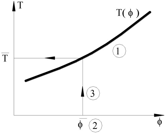
Figure 1.
Simplified schematic of cable force measurement using the frequency method [29].
As can be seen from Figure 1, the frequency method is an indirect method of assessing the cable force, and the testing accuracy depends on the high-sensitivity vibration detection technique and the accuracy of the relationship established between the cable force and the vibration inherent frequency.
2.2. Measurement Method of the Intrinsic Frequency of the Cable
2.2.1. Acquisition of the Intrinsic Frequency of the Cable
The method of the inherent frequency acquisition of the cable can be performed by picking up the time domain signal of a point on the cable under wind excitation by accelerometers and then analyzing the spectrum to obtain its frequency domain spectrum; then, the location of the peak in the spectrum corresponds to a certain order of inherent frequency of the cable [29,30], as shown in Figure 2.
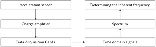
Figure 2.
Figure of measuring scheme.
2.2.2. The Measurement of the Intrinsic Frequency of the Cable Should Pay Attention to the Problem
The whole process of accurately picking up the intrinsic frequency of the cable mainly involves the following technical details.
- (1)
- Filter Frequency: The filtering frequency is selected based on the maximum frequency of interest of the measured cables. Generally, the self-oscillation frequency is calculated based on the ultimate cable force of each cable, and a value five-times its maximum is taken as the filtering frequency;
- (2)
- Sampling frequency: To restore the original signal without distortion, the sampling frequency is at least two-times higher than the filtering frequency;
- (3)
- Sampling time: Due to the simple structure of the cable, the vibration signal is a strong signal; therefore, the sampling time does not need to be very long, and can be determined by comparing the measured frequencies obtained by different adoption times;
- (4)
- Refinement: To improve the resolution of the frequency, the refined FFT technique is used.
2.3. Exploring the Relationship between Cable Force and Frequency
To determine the accurate relationship between the cable force and the vibration inherent frequency and to study the cable force of the Haixin Bridge, in this study, the finite element method was combined with the sample fitting technique [29] for the analysis.
First, the free vibration of a single cable structure (Figure 3) was analyzed using the finite element method, and the characteristic equations were obtained as follows:
where is the stiffness matrix, where is the linear elastic stiffness matrix (related to the bending stiffness of the cable), and is the initial stress stiffness matrix [31] (related to the given cable force); is the circular frequency, , where is the intrinsic frequency; is the mass matrix, and is the vibration type.
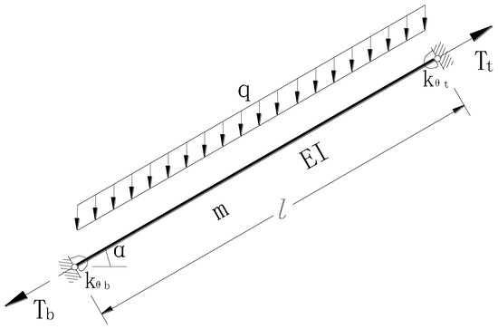
Figure 3.
Cable structure [29].
Second, given the cable force at a certain end of the cable, the initial stress stiffness matrix was calculated for the static force (Figure 3) and substituted into the characteristic equation to obtain the natural frequency of each order = 1, 2, 3, ⋯n; j = 1) under the action of the given cable force.
Third, the analytical method was used to estimate the range of cable force wherein the number of cable forces m was given = 1, 2, 3, ⋯m), and the number of m data pairs (,)( = 1, 2, 3, ⋯; = 1, 2, 3, ⋯m) were calculated using Equation (1).
Fourth, by using the number of data pairs m (,) and the spline fitting technique [32], we obtained the relationship with the first-order intrinsic frequency as follows [29]:
Finally, the measured frequencies of each order of the cable ( = 1, 2, 3, ⋯n) were substituted into Equation (3) to obtain the measured cable force of each order. Considering the various factors affecting the magnitude of each order, the average value of each order was calculated as follows [29]:
3. Investigated Cables and Work Method
3.1. Engineering Background
To study the cable force under the mixed boundary conditions of the ear plate and anchor plate of the curved beam-skewed arch bridge, the world’s longest and widest skewed arch–curved beam pedestrian bridge, Haixin Bridge [33], was selected as the research object. The bridge is located in Guangzhou city and has an arch span of 198.152 m. The bridge has 23 cables; the cable length varies from 12 to 39 m. The upper end of the cable fork ear is connected to the arch upper ear plate, and the lower end of the integral anchor head is connected to the beam upper anchor plate. The bridge layout, full view, finite element model, and cable construction are depicted in Figure 4 and Figure 5.
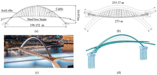
Figure 4.
Bridge layout, appearance map, and finite element model: (a) front view; (b) top view; (c) full view; (d) finite element model.
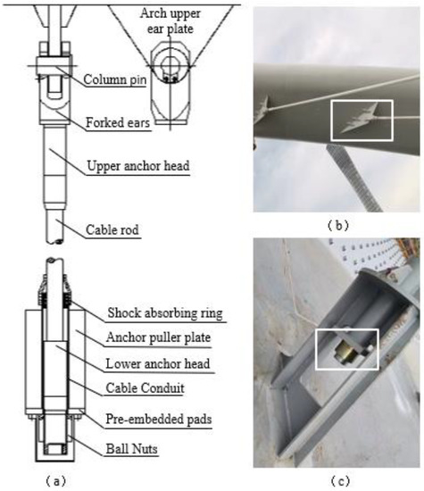
Figure 5.
The actual structure of the cable: (a) structural diagram; (b) upper end of the cable; (c) lower end of the cable.
We selected four cables with uniform distribution, namely, cables 12, 19, 21, and 23, as the research object to perform the sensitivity analysis of cable parameters and identification of cable boundary conditions and bending stiffness; the selected cables are illustrated in Figure 6 and the parameters of the cables are presented in Table 1.
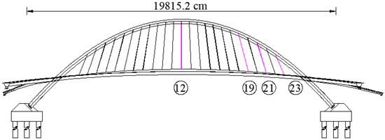
Figure 6.
Bridge cable numbering.

Table 1.
Cable parameters.
3.2. Work Method
3.2.1. The Measurement Method of the Intrinsic Frequency of the Cable of This Project
(1) The Hardware Equipment Used in This Project to Measure the Intrinsic Frequency of the Cable
In this paper, a wireless acceleration acquisition system is used to collect the intrinsic frequency when the tensioning of the cable is completed, as shown in Figure 7.
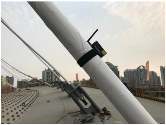
Figure 7.
Field test chart.
The frequency acquisition equipment described in this paper is a wireless acceleration acquisition system, which is includes the integrated equipment of an acceleration sensor, collector, and transmitter, and the manufacturer is Yangzhou Jingming Technology Co, Yangzhou, China. The model is JM5843A, and the specific performance indicators of this acquisition device are shown in Table 2.
Table 2.
The performance indicators of the wireless acceleration acquisition system.
(2) Practical Selection of Equipment Parameters
Using the above equipment, combined with the actual situation of the project, the parameter values were set. The parameter setting table and spectrum diagram are shown below in Table 3 and Figure 8.
Table 3.
Practical selection of equipment parameters.
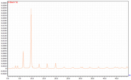
Figure 8.
Frequency spectrum of this project.
3.2.2. Research on the Relationship between Cble Force and Frequency under the Hbrid Boundary between the Ear Plate and the Anchor Plate
(1) Sensitivity Analysis of Cable Parameters
In engineering practice, the actual parameters of the cable are often different from the design parameters. Therefore, to study the influence of each parameter on cable force, we performed a sensitivity analysis of the cable parameters, including cable boundary conditions, bending stiffness, inclination angle, and linear density.
- Boundary Conditions
The actual boundary condition of the cable is between the solid support and hinged support [34]. However, in this study, for the convenience of calculation, the three cable boundary conditions were considered: solid support at both ends, hinged support at both ends, solid support at one end, and hinged support at the other end. To analyze the influence of the boundary conditions on cable force, the cable boundary conditions were used as a single control variable, and the calculated cable bending stiffness, inclination angle, linear density, and other parameters were used for the calculation. The four cables, tensioned to 100% of the design value of some order of the inherent frequency, were selected. Equations (3) and (4) were used to calculate the cable force values at the two ends of the hinged support and two ends of the solid support boundary conditions, and the relative error was calculated. The calculation results are presented in Table 4.
Table 4.
Influence of boundary conditions on cable force.
The following observations can be made from Table 4: (1) The relative errors of the cable force values were above 5%, and the relative error of the 23rd cable was 21.75%. (2) The boundary conditions have a large influence on the cable force of the medium-length cable; the boundary conditions have a small influence on the cable force of the long-length cable. Thus, it can be concluded that the boundary condition has a considerable influence on cable force, and that the effect is more significant for short cables.
- 2.
- Inclination Angle
As the arch bridge form continues to age, the shape of the cable changes, which means that the inclination angle of the cable changes, varying between 0° and 90°. To analyze the influence of the inclination angle on the cable force, the cable inclination angle was used as a single control variable, the cable inclination angle was selected as 0° and 90°, and the actual cable bending stiffness, boundary conditions, linear density, and other parameters were used for the calculation. We selected four cables tensioned to 100% of the design value of some order of the inherent frequency, used Equations (3) and (4) to determine the cable force value for the cable inclination angle varying between 0° and 90°, and calculated the relative error. The calculation results are presented in Table 5.
Table 5.
Influence of inclination angle on cable force.
The following observations can be made from Table 5: (1) The calculated cable force values at an inclination angle of 90° were greater than the calculated cable force values at an inclination angle of 0°. (2) The inclination angle exhibited little influence on the cable force values of the four cables, and the influence on the long cables was found to be greater than that on the short cables. Thus, it can be concluded that the inclination angle has little influence on the cable force.
- 3.
- Bending Stiffness
The actual bending stiffness of the bridge cable is not equal to the theoretical bending stiffness of the cable calculated according to the section characteristics. The actual bending stiffness of the cable varies due to certain factors and is between the zero bending stiffness and the maximum bending stiffness calculated according to the full section. To analyze the influence of the bending stiffness on cable force, the bending stiffness of the cable was used as a single control variable, the zero bending stiffness and maximum bending stiffness of the cable were considered, and the actual boundary conditions and inclination angle, linear density, and other parameters were used for the calculation. We selected the four cables tensioned to 100% of the design value of some order of the inherent frequency, used Equations (3) and (4) to obtain the cable force value under zero bending stiffness and maximum bending stiffness, and calculated the relative error. The calculation results are presented in Table 6.
Table 6.
Influence of bending stiffness on cable force.
The following observations were made from Table 6: (1) The calculated cable force values for the zero bending stiffness are greater than the calculated cable force values for the maximum bending stiffness. (2) The bending stiffness of the cable exhibited a considerable influence on the force of the four cables, and the influence on the short cable was significantly greater than that on the long cable, and the relative error was 60.29%. This shows that the bending stiffness influences the cable force, and that the effect is more significant for short cables.
- 4.
- Linear Density
The influence of factors such as processing errors in the manufacturing process and uneven quality distribution at the anchorage end of the bridge cable leads to the uneven distribution of cable linear density through the length of the cable, deviating from the cable design linear density to a certain extent. To analyze the influence of cable linear density on cable force, the cable linear density was used as a single control variable, deviating from the design linear density by +5% and +10%, and the actual boundary conditions, inclination angle, bending stiffness, and other parameters were used for the calculation. We selected the four cables tensioned to 100% of the design value of some order of the inherent frequency, used Equations (3) and (4) to determine the cable force value for the deviation of +5% and +10% from the design linear density, and calculated the relative error. The calculation results are presented in Table 7.
Table 7.
Influence of linear density on cable force.
The following observations can be made from Table 7: (1) The deviation from the design linear density +5% calculated cable force values were smaller than that from the design linear density +10% calculated cable force values. (2) The effect of cable linear density of the four cable forces on the cable force was noted to be high. Thus, it can be concluded that linear density affects the cable force considerably.
(2) Process for Determining the Bending Stiffness and Boundary Conditions of Cables
The results for the sensitivity of the cable force to cable parameters revealed that the cable boundary conditions, bending stiffness, and linear density have a considerable effect on the cable force. The cable linear density is provided by the manufacturer; thus, only the cable boundary conditions and bending stiffness need to be determined. Therefore, in this study, we employed the mixed boundary condition and bending stiffness determination for the cables of the curved beam and skewed arch ear plate and anchor plate. The main processes are as follows and are illustrated in Figure 9.
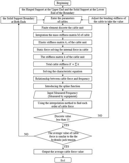
Figure 9.
Flow chart of force testing.
- (1)
- The preliminary boundary conditions were set. The upper end of the cable was connected to the upper ear plate of the arch through the fork ear, which is hinged in the longitudinal direction and solid in the transverse direction [35]. In the case of the upper ear plate connection of the cable of the curved beam and skewed arch and the installation position of the on-site sensor, the upper end is hinged, and the lower end is connected to the anchor plate of the beam through the integral anchor, which can be solid;
- (2)
- The intrinsic frequency when the cable was tensioned to 100% of the design value was selected. An acceleration sensor was used to collect the time domain signal of the response of a point on the cable under natural excitation. Then, the frequency domain spectrum was obtained by performing a frequency domain analysis of the time domain signal. Next, the frequency domain spectrum was used to select some order of the intrinsic frequency;
- (3)
- The relationship between cable force and frequency was determined for the hinged upper end and solid lower end boundary conditions. A combination of the finite element method and spline fitting technique was used to calculate the cable force versus frequency for a given cable force range;
- (4)
- The bending stiffness of the cable was determined under the boundary condition of the hinged support at the upper end and solid support at the lower end. The cable bending stiffness was selected as 0.02EImax–0.2EImax, with a step increment of 0.02EImax. By using the combination of the finite element method and spline fitting technique, the relationship between frequency and cable bending stiffness was determined by studying the cable bending stiffness values under the hinged support at the upper end and solid support at the lower end boundary conditions. By using the principle of difference, the calculated cable force value under some order of frequency was obtained. In addition, the bending stiffness of the cable was determined based on the uniqueness of the cable force;
- (5)
- The boundary conditions were adjusted. If the difference between the average value of the calculated cable force at some order of inherent frequency and the value of the hydraulic jack tension at the site of the cable pulling device was large and the dispersion of the calculated cable force at some order of inherent frequency was greater than 15, the boundary condition of the cable was changed to the solid support at both ends;
- (6)
- The relationship between cable force and frequency was determined under solid support boundary conditions at both ends. The aforementioned method was used to determine the effect of frequency on the solid cable force at both ends for a given range of the cable force;
- (7)
- The bending stiffness of the cable was determined under solid support boundary conditions at both ends. The same identification method was used to determine the bending stiffness of the cable under the boundary condition of the hinged support at the upper end and the solid support at the lower end, and the actual bending stiffness of the cable in this state was obtained;
- (8)
- The actual boundary conditions and bending stiffness of the cable were obtained by comparing and analyzing the hinged support at the upper end and the solid support at the lower end boundary conditions and the calculated cable force values under the boundary conditions of the solid support at both ends and the hydraulic jack tension values of the field cable pulling device.
4. Results and Discussions
4.1. Determination of the Bending Stiffness of the Cable under the Hinged Support at the Upper End and the Solid Support at the Lower End of the Boundary
We selected certain order inherent frequencies of the four cables tensioned to 100% of the design value as the research object. The 23rd cable was the shortest; thus, the first three order inherent frequencies were considered to be more accurate. The certain order inherent frequencies of the four cables are presented in Table 8.
Table 8.
The measured frequency of the certain order of the cable during the tensioning process.
4.1.1. Relationship between Cable Force and Frequency
Based on the preliminary determination of the boundary conditions of the cable as the hinged support at the upper end and the solid support at the lower end, the aforementioned finite element method combined with the sample fitting technique was used to calculate the frequencies of each order under the given cable force range. The cable force versus frequency curves were obtained for the four cables, as shown in Figure 10.
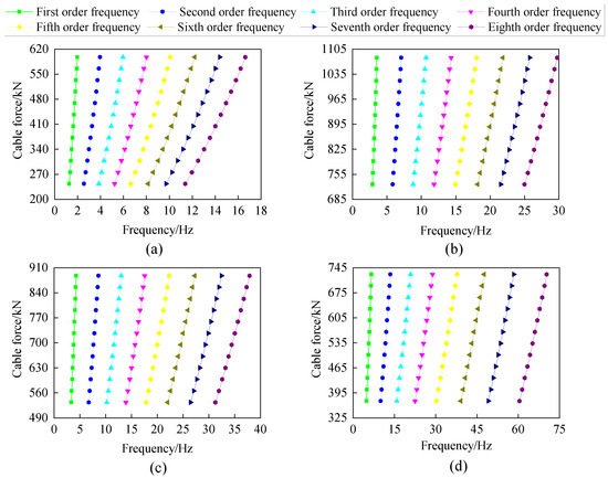
Figure 10.
Relationship between the cable force and frequency at the boundary of upper hinged support and lower solid support: (a) 12th cable; (b) 19th cable; (c) 21st cable; (d) 23rd cable.
4.1.2. Determining the Bending Stiffness
According to step 4, a bending stiffness value of 0.02EImax–0.2EImax for each cable was taken, and the cable was tensioned to 100% of the design value of the inherent frequency and selected under the principle of difference in the cable force and frequency relationship; then, the bending stiffness value under some order inherent frequency corresponding to the value of the cable force was calculated for each cable. The calculation results are presented in Figure 11.
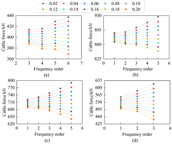
Figure 11.
Measured cable force of the boundary of upper hinged support and lower solid support (legend is the times of maximum bending stiffness): (a) 12th cable; (b) 19th cable; (c) 21st cable; (d) 23rd cable.
As can be seen from Figure 11, when the bending stiffness of the cable was 0.12EImax, the measured cable force values corresponding to some order of the intrinsic frequency almost formed a horizontal, straight line, which satisfies the uniqueness of the cable force. According to the actual bending stiffness of the hinged support at the upper end and the solid support at the lower end boundary conditions, the cable force was calculated and compared with the actual tensioning force of the hydraulic jack on site (Table 9).
Table 9.
Comparison of the cable force values.
As can be seen from the calculation results presented in Table 9, the actual bending stiffness of the hinged support at the upper end and the solid support at the lower end boundary conditions under the calculated cable force value and the actual tension value of the hydraulic jack of the field tensioning device deviated greatly; thus, the cable boundary conditions were adjusted for the two ends of the solid support to accurately determine the bending stiffness.
4.2. Determination of the Bending Stiffness of the Cable under the Solid Support Boundary at Both Ends
4.2.1. Relationship between Cable Force and Frequency
The frequency of each order at a given cable force for a given range of cable force was calculated by combining the finite element method with the sample fitting technique, and the cable force versus frequency graph is illustrated in Figure 12.
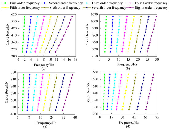
Figure 12.
Relationship between the cable force and the frequency at the boundary of solid support at both ends: (a) 12th cable; (b) 19th cable; (c) 21st cable; (d) 23rd cable.
4.2.2. Determination of Bending Stiffness
According to the aforementioned method of determining the bending stiffness of the cable under the boundary condition of hinged support at the upper end and solid support at the lower end, the determination of the bending stiffness of the tension cable under the boundary condition of solid support at both ends was performed; the results are depicted in Figure 13.
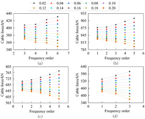
Figure 13.
Measured cable force of solid support at both ends (legend is the amount of maximum bending stiffness): (a) 12th cable; (b) 19th cable; (c) 21st cable; (d) 23rd cable.
As can be seen from Figure 13, when the bending stiffness value of the cable was 0.12EImax, the measured cable force values corresponding to some order of the intrinsic frequency almost formed a horizontal straight line, which satisfies the uniqueness of the cable force. The cable force value and the actual pulling force value of the hydraulic jack of the site cable pulling device, according to the actual bending stiffness value under the solid support boundary conditions at both ends, are presented in Table 10.
Table 10.
Comparison of cable force values.
4.3. Boundary Conditions and Bending Stiffness Results of the Cable
A comprehensive comparison of the actual cable bending stiffness, calculated cable force value, and the actual tension value of the hydraulic jack of the site cable pulling device for the two ends of the solid support boundary conditions, the upper end of the hinged support, and the lower end of the solid support boundary conditions was performed; the results are shown in Figure 14.
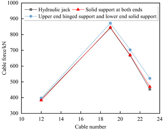
Figure 14.
Comparison of the cable force values.
From Figure 14, it can be seen that the actual bending stiffness of the cable under the boundary conditions of the two ends of the solid support calculated cable force value and the actual tension value of the hydraulic jack of the site cable pulling device showed good agreement; the maximum relative error was within 3.5%. Therefore, the actual boundary condition of the hybrid boundary between the ear plate and the anchor plate is solidly supported at both ends, and the actual bending stiffness of the cable is taken as 0.12EImax.
5. Conclusions
Based on the research results, the cables of the bridge described in this paper were guided to perform the cable force test, and the final state of the bridge was consistent with the theoretical calculation, which indirectly illustrates the accuracy and operability of the method in this paper.
In this study, we performed the sensitivity analysis of cable parameters and determined the cable boundary conditions and bending stiffness for the cable under the mixed boundary conditions of the ear plate and anchor plate of the curved beam-skewed arch pedestrian bridge. The following conclusions can be drawn:
- (1)
- Boundary conditions, bending stiffness, and linear density affect the cable force considerably, whereas the inclination angle has little influence on the cable force;
- (2)
- During the measurement of the cable force of this bridge, the results of the bending stiffness of the cable in the tensioning process was 0.12EImax under the boundary conditions of the hinged support at the upper end, the solid support at the lower end, and the solid support at both ends;
- (3)
- The actual bending stiffness of the cable under the boundary conditions of the two ends of the solid support which calculated the cable force value and the actual tension value of the hydraulic jack of the site cable pulling device showed good agreement; the maximum relative error was within 3.5%;
- (4)
- When the cable belongs to the ultra-short cable (within 5 m), the influence of the bending stiffness and boundary conditions of the cable on the cable force test will become larger, and the values of the bending stiffness and boundary conditions identified in this paper may not be applicable; however, the method of identifying the bending stiffness and boundary conditions proposed in this paper is still available;
- (5)
- When the cable belongs to the extra-long cable, the bending stiffness and boundary conditions of the cable have less influence on the cable force test, and the values of the bending stiffness and boundary conditions have less influence on the cable force test results; moreover, even without considering the influence of the bending stiffness and boundary conditions, the results of the cable force test do not differ much.
Author Contributions
The authors confirm their contribution to the paper as follows: study conception and design: Y.X. (Yufeng Xu) and Y.X. (Yunfei Xie); data collection: Y.X. (Yunfei Xie), S.C. and M.Z.; analysis and interpretation of results: Y.X. (Yunfei Xie); draft manuscript preparation: Y.X. (Yunfei Xie) and Y.X. (Yufeng Xu). All authors have read and agreed to the published version of the manuscript.
Funding
This research received no external funding.
Data Availability Statement
N/A, data supporting the results reported in the article can be found in the figures and tables included in this paper.
Conflicts of Interest
These authors declare no conflict of interest.
References
- Ni, Y.; Ko, J.; Zheng, G. Dynamic analysis of large-diameter sagged cables taking into account flexural rigidity. J. Sound Vib. 2002, 257, 301–319. [Google Scholar] [CrossRef]
- Huang, Y.-H.; Fu, J.-Y.; Wang, R.-H.; Gan, Q.; Liu, A.-R. Unified practical formulas for vibration-based method of cable tension estimation. Adv. Struct. Eng. 2015, 18, 405–422. [Google Scholar] [CrossRef]
- Zhang, Y.; Su, C.; Deng, Y. A eulerian video magnification based cable tension identification method for bridge structures. J. Graph. 2022, 42, 941. [Google Scholar]
- Jana, D.; Nagarajaiah, S. Computer vision-based real-time cable tension estimation in Dubrovnik cable-stayed bridge using moving handheld video camera. Struct. Control Health Monit. 2021, 28, e2713. [Google Scholar] [CrossRef]
- Qi, Q.; Zhang, R.; Hu, R.; Wang, C. Experimental study on the variation law of cable force during construction of tied arch bridges. J. Railw. Sci. Eng. 2017, 14, 1893–1898. [Google Scholar] [CrossRef]
- Huo, X.; Gao, L.; Wu, X. Study on the optimization of construction cable tensions for multi-rib butterfly-shape arch bridges. J. Highw. Transp. Res. Dev. 2012, 6, 56–64. [Google Scholar] [CrossRef]
- Wang, J.; Liu, W.; Wang, L.; Han, X. Estimation of main cable tension force of suspension bridges based on ambient vibration frequency measurements. Struct. Eng. Mech. 2015, 56, 939–957. [Google Scholar] [CrossRef]
- Nazarian, E.; Ansari, F.; Zhang, X.; Taylor, T. Detection of tension loss in cables of cable-stayed bridges by distributed monitoring of bridge deck strains. J. Struct. Eng. 2016, 142, 04016018. [Google Scholar] [CrossRef]
- Syamsi, M.I.; Wang, C.; Nguyen, V. Tension force identification for cable of various end-restraints using equivalent effective vibration lengths of mode pairs. Measurement 2022, 197, 111319. [Google Scholar] [CrossRef]
- Su, C.; Xu, Y.; Han, D. Application of Finite Element Method and Spline Fitting Technique in Frequency Method to Measure Cable Force. Highway 2004, 12, 28–31. [Google Scholar]
- Dan, D.; Chen, Y.; Yan, X. Determination of cable force based on the corrected numerical solution of cable vibration frequency equations. Struct. Eng. Mech. 2014, 50, 37–52. [Google Scholar] [CrossRef]
- He, R.; Yan, P.; He, W.; Chen, H. Tension measurement of arch bridge suspender considering environmental temperature and other factors influence. J. Vib. Meas. Diagn. 2020, 40, 873–880. [Google Scholar] [CrossRef]
- Caetano, E. On the Identification of Cable Force from Vibration Measurements; IABSE-IASS Symposium: London, UK, 2011. [Google Scholar]
- Ma, L. A highly precise frequency-based method for estimating the tension of an inclined cable with unknown boundary conditions. J. Sound Vib. 2017, 409, 65–80. [Google Scholar] [CrossRef]
- Kangas, S.; Helmicki, A.; Hunt, V.; Sexton, R.; Swanson, J. Cable-stayed bridges: Case study for ambient vibration-based cable tension estimation. J. Bridge Eng. 2012, 17, 839–846. [Google Scholar] [CrossRef]
- Geier, R.; De Roeck, G.; Petz, J. Cable force determination for the Danube channel bridge in Vienna. Struct. Eng. Int. 2005, 15, 181–185. [Google Scholar] [CrossRef]
- Fang, Z.; Wang, J. Practical formula for cable tension estimation by vibration method. J. Bridge Eng. 2012, 17, 161–164. [Google Scholar] [CrossRef]
- Yan, B.; Chen, W.; Yu, J.; Jiang, X. Mode shape-aided tension force estimation of cable with arbitrary boundary conditions. J. Sound Vib. 2019, 440, 315–331. [Google Scholar] [CrossRef]
- Zui, H.; Shinke, T.; Namita, Y. Practical formulas for estimation of cable tension by vibration method. J. Struct. Eng. 1996, 122, 651–656. [Google Scholar] [CrossRef]
- Ceballos, M.A.; Prato, C.A. Determination of the axial force on stay cables accounting for their bending stiffness and rotational end restraints by free vibration tests. J. Sound Vib. 2008, 317, 127–141. [Google Scholar] [CrossRef]
- Li, S.; Li, H.; Liu, Y.; Lan, C.; Zhou, W.; Ou, J. SMC structural health monitoring benchmark problem using monitored data from an actual cable-stayed bridge. Struct. Control Health Monit. 2014, 21, 156–172. [Google Scholar] [CrossRef]
- Kim, B.H.; Park, T. Estimation of cable tension force using the frequency-based system identification method. J. Sound Vib. 2007, 304, 660–676. [Google Scholar] [CrossRef]
- Nam, H.; Nghia, N. Estimation of cable tension using measured natural frequencies. Procedia Eng. 2011, 14, 1510–1517. [Google Scholar] [CrossRef]
- Yong-Hui, H.; Ji-Yang, F.; Rong-Hui, W.; Quan, G.; Rui, R.; Ai-Rong, L. Practical formula to calculate tension of vertical cable with hinged-fixed conditions based on vibration method. J. Vibroeng. 2014, 16, 997–1009. [Google Scholar]
- Ai, Y.; Huang, F.; Feng, F.; Huang, Q. Theoretical calculation of suspender tension based on frequency method. J. Railw. Sci. Eng. 2020, 17, 2030–2036. [Google Scholar] [CrossRef]
- Yi, D.; Liu, X. Study on cable force test of arch bridge steel box basket based on the frequency method. J. China Foreign Highw. 2021, 41, 154–158. [Google Scholar] [CrossRef]
- Yan, Q.; Liu, S.; Zhu, Z.; Li, D. Determing short suspender tension based on frequency method. J. Railw. Sci. Eng. 2020, 17, 2577–2585. [Google Scholar]
- Li, R.; Li, X.; Zheng, X.; Zhou, Y. Application of PSO in frequency-based tension identification of hanger rods two fixed ends. J. Vib. Shock 2018, 37, 196–201. [Google Scholar] [CrossRef]
- Xu, Y. Research on Theory and Key Technologies of Construction Control for Long-Span Prestressed Concrete Cable-Stayed Bridge and Sowfware Development; South China University of Technology: Guangzhou, China, 2004. [Google Scholar]
- Liu, S.; Jiang, D.; Li, S. Application of optic fiber grating vibration sensor to cable tension measuring of cable-stayed bridges. J. Wuhan Univ. Technol. 2006, 28, 110–121. [Google Scholar]
- Wang, X.; Shao, M. Fundamental Principles and Numerical Methods of Finite Element Method; Tsinghua University Press Co., Ltd.: Tsinghua, China, 1997. [Google Scholar]
- Li, Q. Numerical Analysis; Tsinghua University Press Co., Ltd.: Tsinghua, China, 2001. [Google Scholar]
- The world’s largest skew arch and curved beam pedestrian bridge Guangzhou’s first pedestrian bridge on both sides of the Pearl River is about to be completed. Munic. Technol. 2021, 39, 55.
- Xu, X.; Ren, W. Effect of boundary conditions on the estimation of suspender tension. Chin. J. Railw. Sci. Eng. 2008, 5, 26–31. [Google Scholar] [CrossRef]
- Yuan, J. Study on Cable Tension Estimation by Frequency Method Considering the Effect of Extreme Properties; Harbin Institute of Technology: Harbin, China, 2017. [Google Scholar]


Publisher’s Note: MDPI stays neutral with regard to jurisdictional claims in published maps and institutional affiliations. |
© 2022 by the authors. Licensee MDPI, Basel, Switzerland. This article is an open access article distributed under the terms and conditions of the Creative Commons Attribution (CC BY) license (https://creativecommons.org/licenses/by/4.0/).