
Repair and Protection of Existing Steel-Reinforced Concrete Structures with High-Strength, Textile-Reinforced Mortars

 , ,
, ,  and
and
Abstract
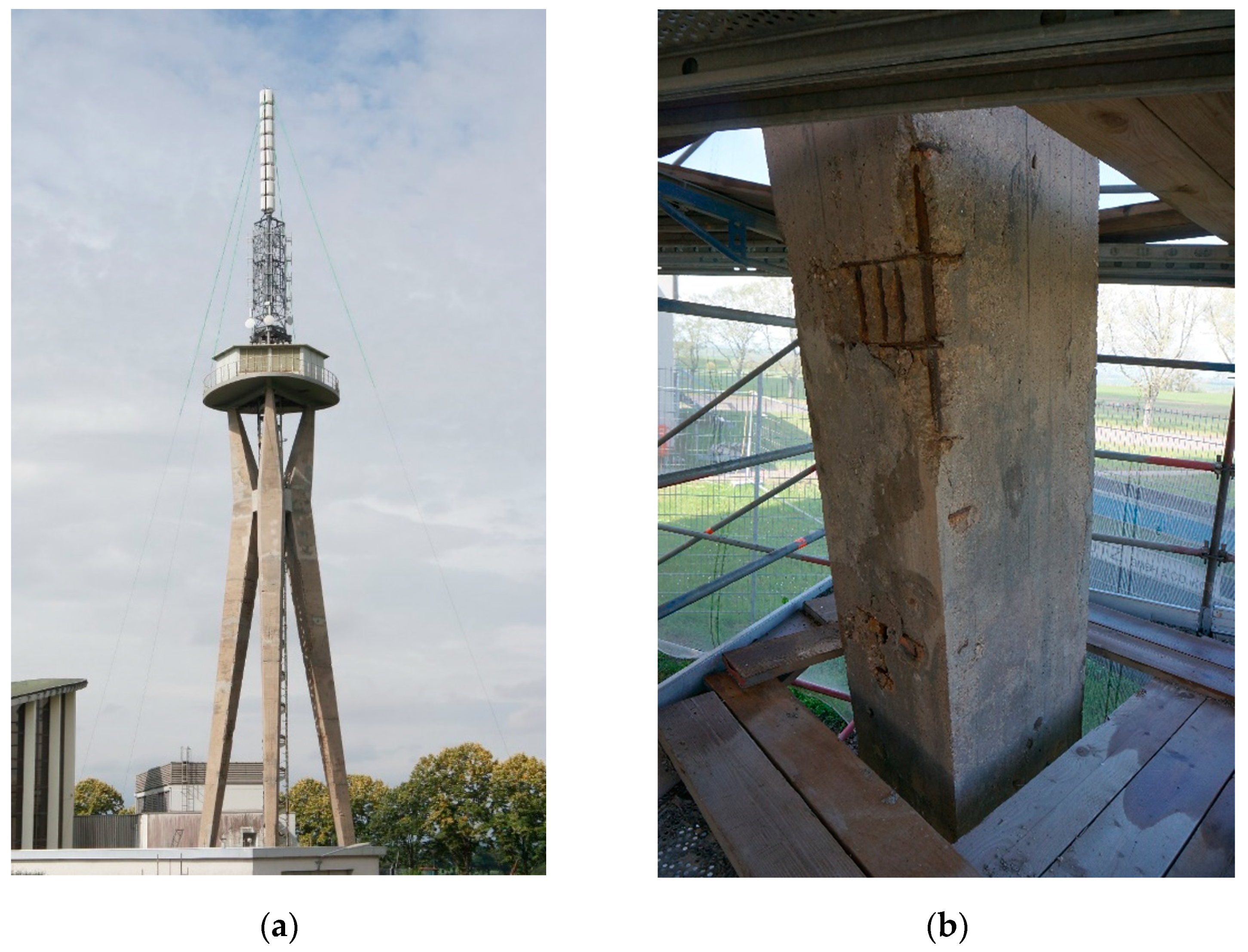
:1. Introduction
- local reinforced concrete replacement.
2. Development of a Specific Textile-Reinforced Cement Mortar
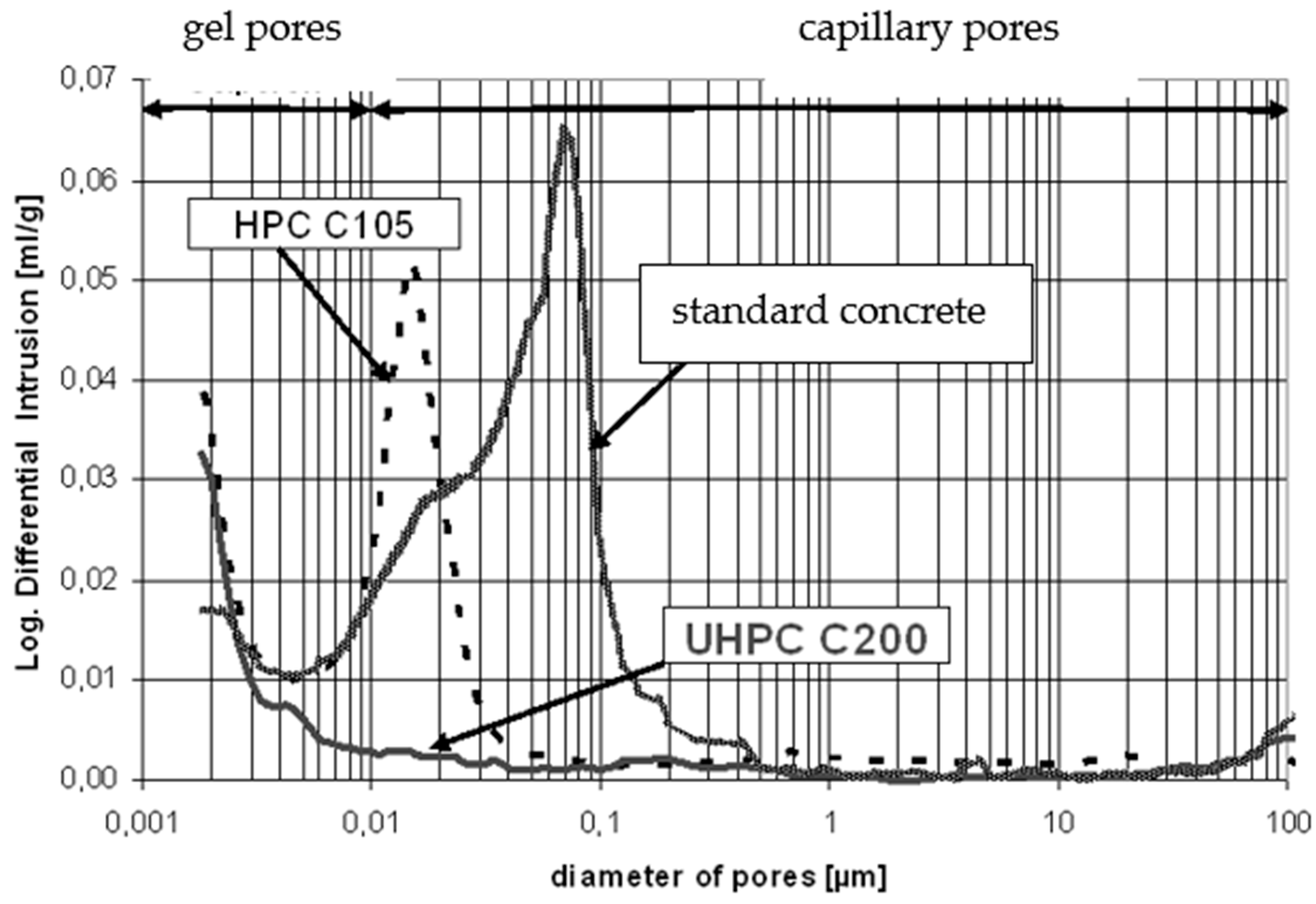
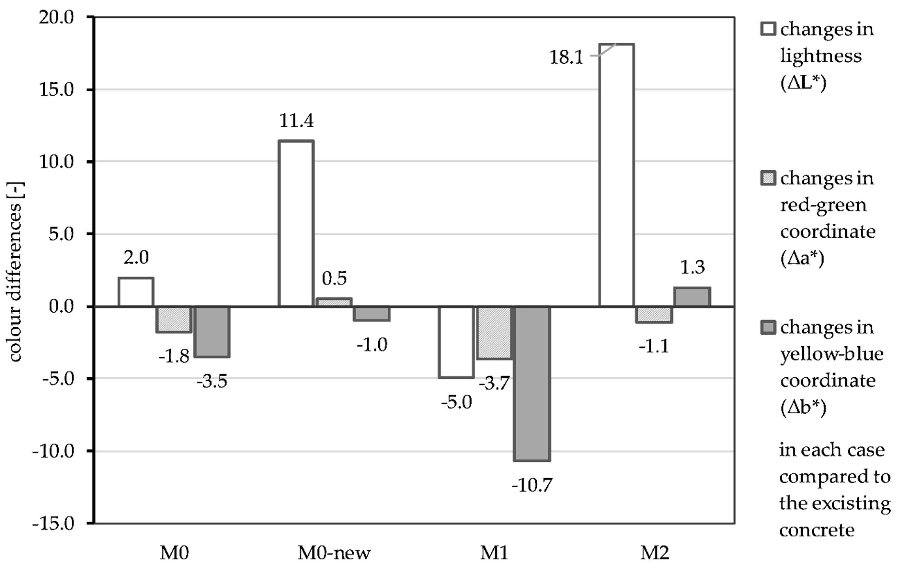
2.1. Compatible High-Performance Cement Mortar
2.2. Textile Reinforcement
2.3. Composite Material
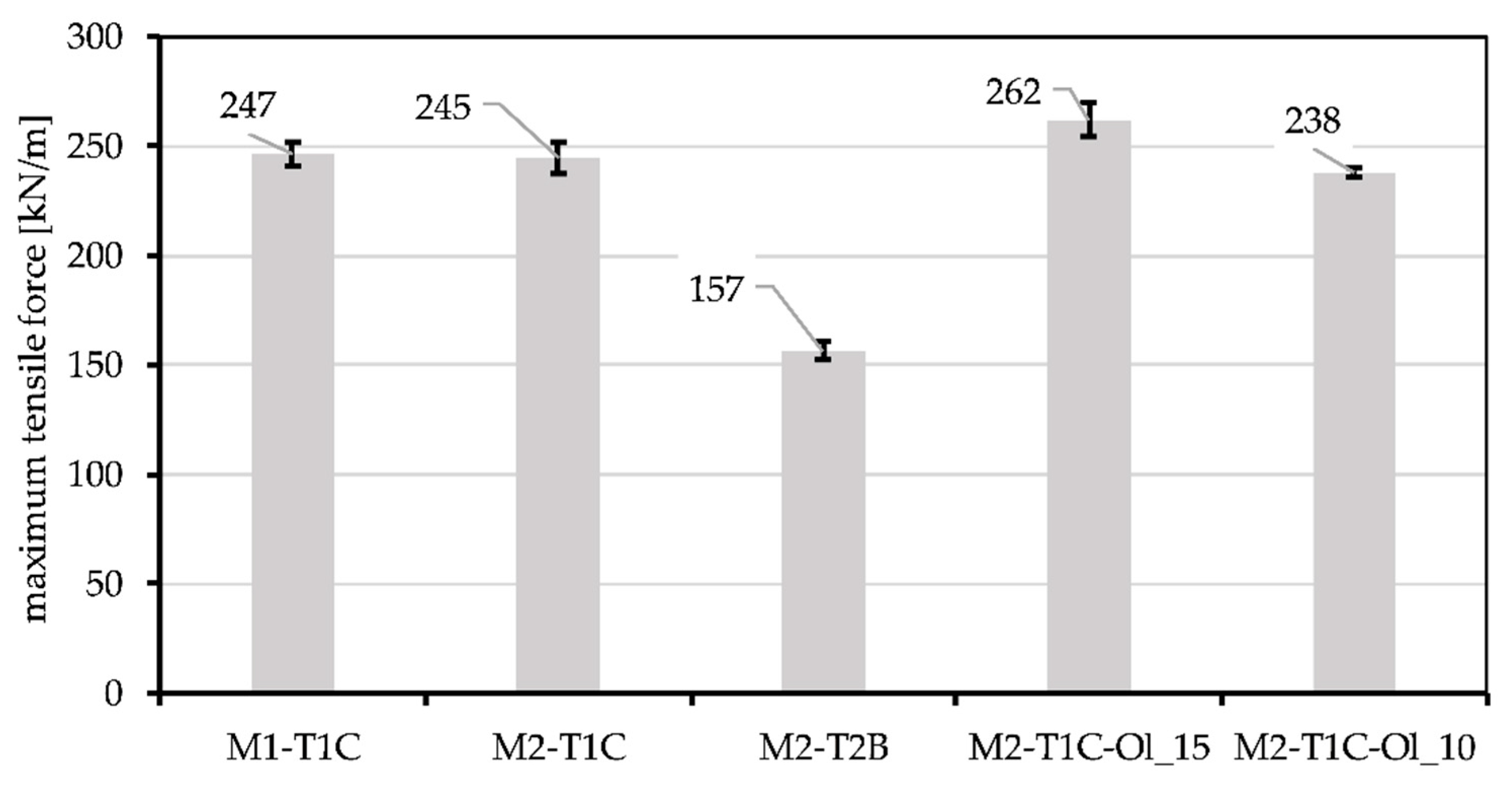
- applicable maximum tensile force (kN/m) to enlarge or restore the load-bearing capacity of the existing structure (in the ultimate limit state);
- small crack spacings and crack openings to reduce the penetration of pollutants into the existing structure;
- appropriate processing properties.
- M1 with two layers, T 1C;
- M2 with two layers, T 1C;
- M2 with four layers, T 2B.
3. Characterization of Textile-Reinforced Mortar (TRM) as Repair Material
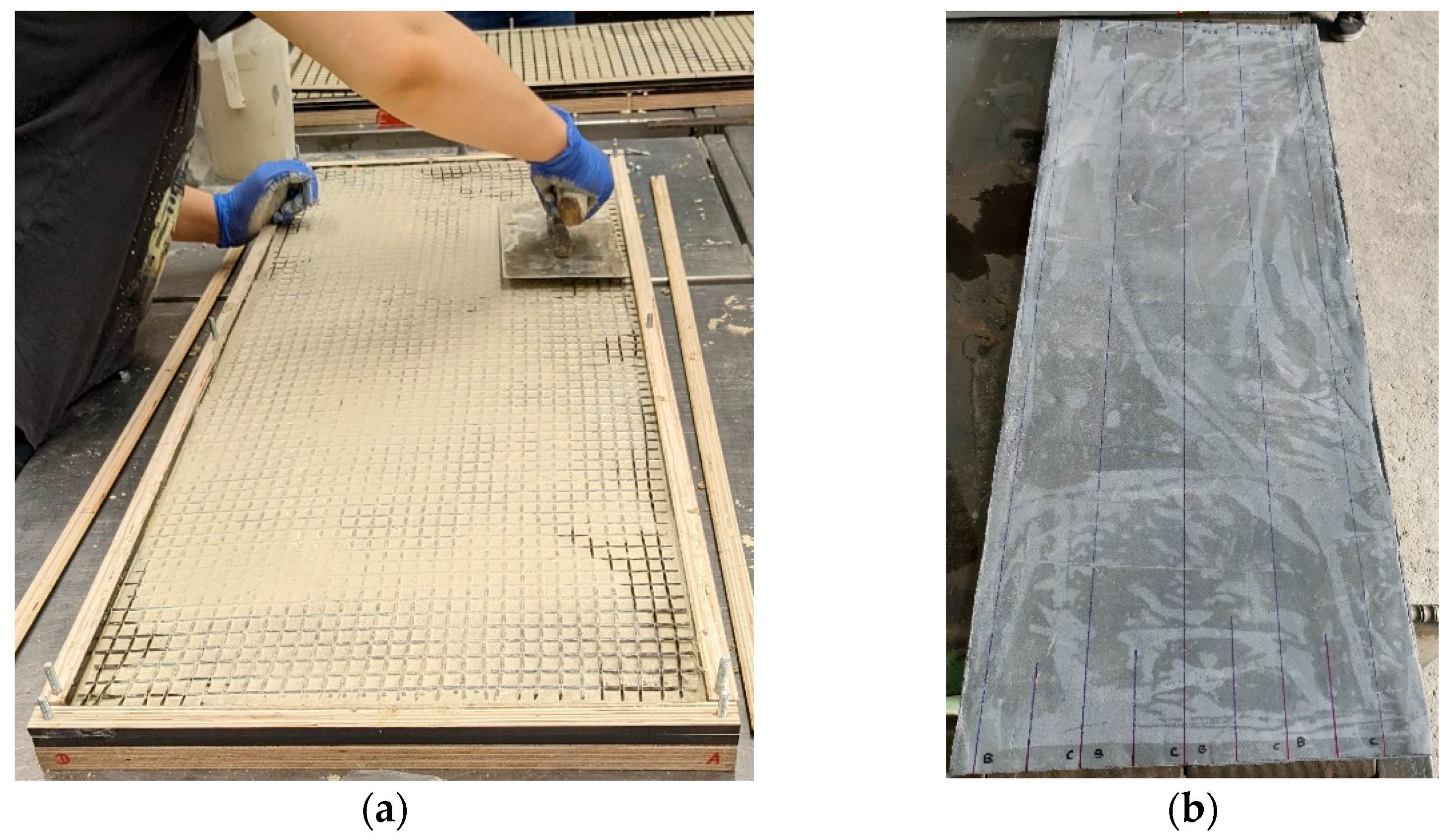
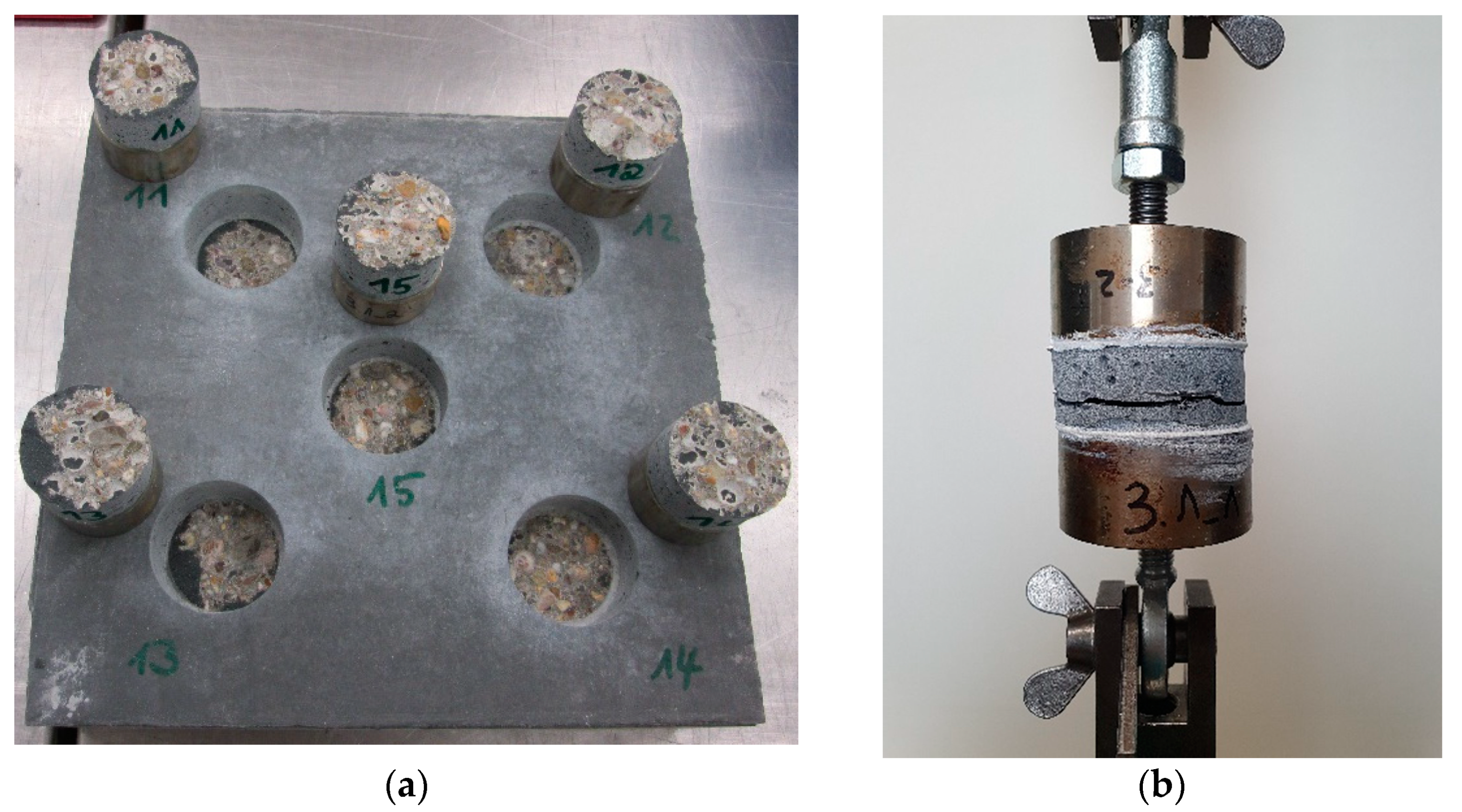
3.1. Specimen Preparation
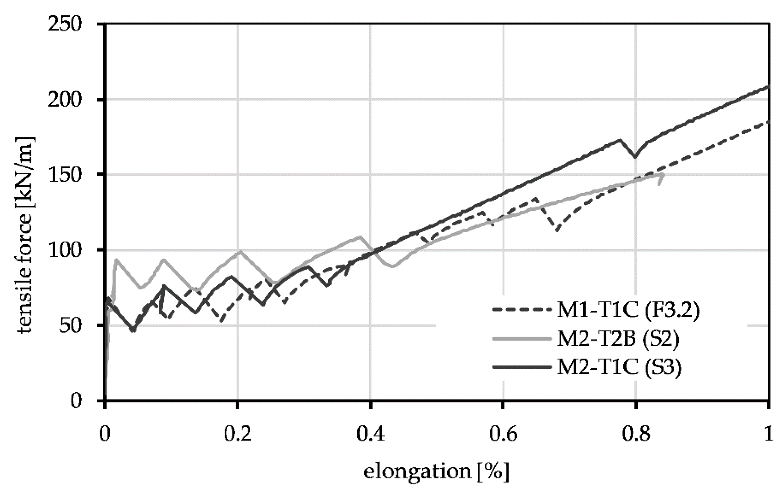
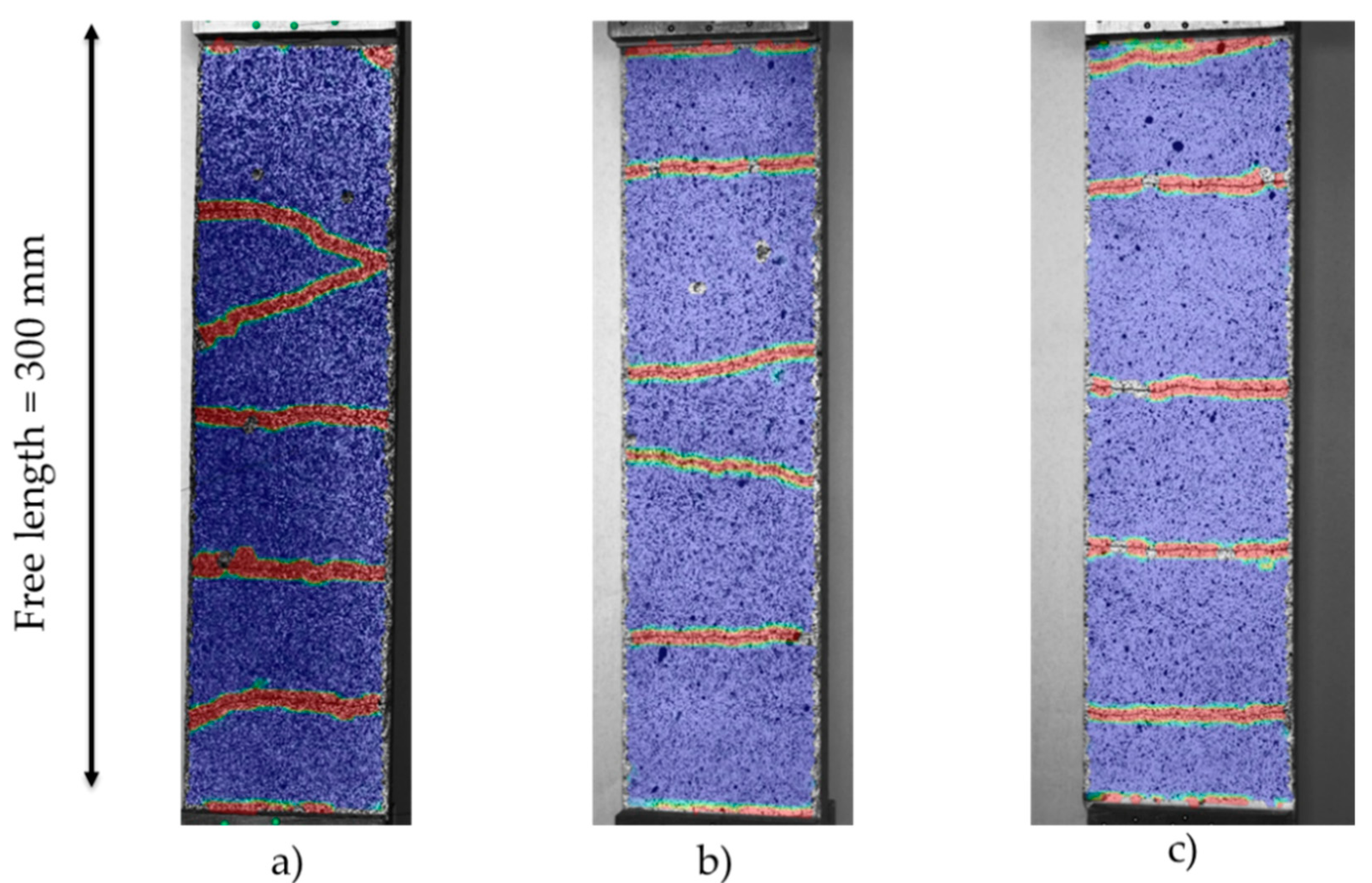
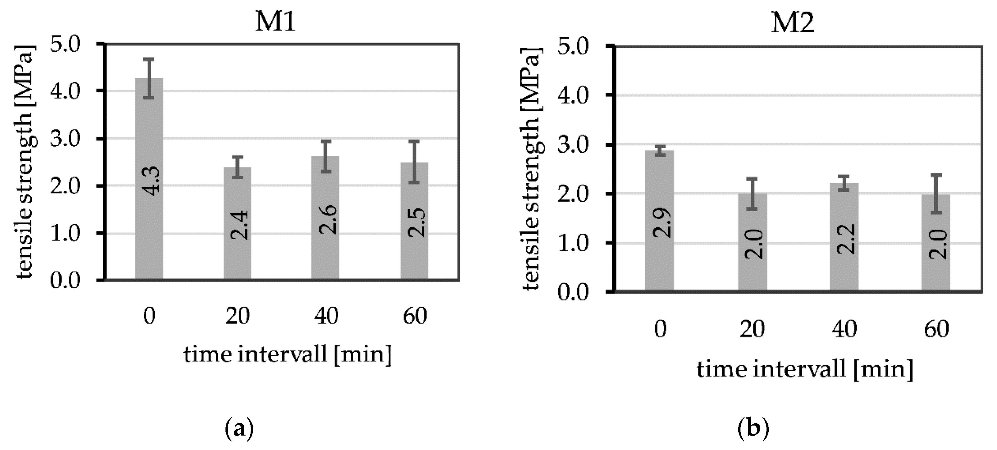
3.2. Tensile Tests
3.3. Determination of the Overlapping Length
3.4. Lateral Tensile Tests
4. Discussion
5. Conclusions and Outlook
Author Contributions
Funding
Institutional Review Board Statement
Informed Consent Statement
Data Availability Statement
Acknowledgments
Conflicts of Interest
References
- Brameshuber, W. Textile Reinforced Concrete. State-of-the-Art Report of RILEM Technical Committee 201-TRC; RILEM Publications S.A.R.L.: Bagneux, France, 2006; ISBN 2-912143-99-3. [Google Scholar]
- Curbach, M.; Ortlepp, R. Textilbeton in Theorie und Praxis. In Tagungsband zum 6. Kolloquium zu Textilbewehrten Tragwerken (CTRS6), Proceedings of the Gemeinsames Abschlusskolloquium der Sonderforschungsbereiche 528 (Dresden) und 532 (Aachen), Berlin, Germany, 19–20 September 2011; Technical University of Dresden: Dresden, Germany, 2011; ISBN 9783867802451. [Google Scholar]
- Lieboldt, M.; Tietze, M.; Schladitz, F. C³-Projekt—Erfolgreiche Partnerschaft für Innovation im Bauwesen. Bauingenieur 2018, 93, 265–273. [Google Scholar] [CrossRef]
- Technische Universität Dresden. Sonderforschungsbereich/Transregio 280. Available online: https://www.sfbtrr280.de/?msclkid=9354f413b4eb11ecae578e325129b66b (accessed on 1 September 2022).
- Heid, A.-C.; Stark, A.; Will, N.; Hegger, J. Weitspannende Sandwichelemente mit vorgespannten Textilbetondeckschichten und geschäumter Kernschicht. BUST 2021, 116, 498–507. [Google Scholar] [CrossRef]
- Orlowsky, J.; Maurer, R.; Heeke, G.; Beßling, M.; Bettin, M. Ressourcenschonende Lärmschutzelemente aus Textilbeton als Alternative für konventionelle Stahlbetonfertigteile—Resource-saving noise protection elements made of textile reinforced concrete as an alternative for conventional precast reinforced concrete elements. Beton Stahlbetonbau 2021, 116, 947–957. [Google Scholar] [CrossRef]
- Hegger, J.; Curbach, M.; Stark, A.; Wilhelm, S.; Farwig, K. Innovative design concepts: Application of textile reinforced concrete to shell structures. Struct. Concr. 2018, 19, 637–646. [Google Scholar] [CrossRef]
- Papanicolaou, C.G. Applications of textile-reinforced concrete in the precast industry. In Textile Fibre Composites in Civil Engineering; Triantafillou, T., Ed.; Woodhead Publishing: Duxford, UK, 2016; pp. 227–244. ISBN 9781782424468. [Google Scholar]
- Beßling, M.; Antons, U.; Orlowsky, J. Potentials of Textile Reinforced Concrete for Lightweight Noise Protection Walls. In High Tech Concrete: Where Technology and Engineering Meet; Hordijk, D.A., Luković, M., Eds.; Springer International Publishing: Cham, Switzerland, 2018; pp. 2538–2545. ISBN 978-3-319-59470-5. [Google Scholar]
- Du, Y.X.; Shao, X.; Chu, S.H.; Zhou, F.; Su, R.K.L. Strengthening of preloaded RC beams using prestressed carbon textile reinforced mortar plates. Structures 2021, 30, 735–744. [Google Scholar] [CrossRef]
- Zdanowicz, K.; Marx, S. Flexural behaviour of thin textile reinforced concrete slabs enhanced by chemical prestressing. Eng. Struct. 2022, 256, 113946. [Google Scholar] [CrossRef]
- Koutas, L.N.; Tetta, Z.; Bournas, D.A.; Triantafillou, T.C. Strengthening of Concrete Structures with Textile Reinforced Mortars: State-of-the-Art Review. J. Compos. Constr. 2019, 23, 03118001. [Google Scholar] [CrossRef]
- Brückner, A.; Ortlepp, R.; Curbach, M. Anchoring of shear strengthening for T-beams made of textile reinforced concrete (TRC). Mater. Struct. 2008, 41, 407–418. [Google Scholar] [CrossRef]
- Ortlepp, R.; Ortlepp, S. Textile reinforced concrete for strengthening of RC columns: A contribution to resource conservation through the preservation of structures. Constr. Build. Mater. 2017, 132, 150–160. [Google Scholar] [CrossRef]
- Wertenbroch, A. Verstärkung von Mauwerwerkswänden mit textilbewehrten Betonelementen zur Verbesserung der Trageigenschaften unter Erdbebenbeanspruchung. Ph.D. Thesis, Technische Universität Dortmund, Dortmund, Germany, 2017. [Google Scholar]
- Büttner, T.; Morales Cruz, C.; Raupach, M. Dauerhafte Schutzschichten aus Textilbeton für Bauwerksoberflächen im Wasserbau. Bautechnik 2013, 90, 485–490. [Google Scholar] [CrossRef]
- Cruz, C.M. Crack-distributing Carbon Textile Reinforced Concrete Protection Layers. Ph.D. Thesis, RWTH Aachen, Aachen, Germany, 2020. [Google Scholar]
- Bundesanstalt für Wasserbau. BAWMerkblatt: Flächige Instandsetzung von Wasserbauwerken mit textilbewehrten Mörtel- und Betonschichten (MITEX); Bundesanstalt für Wasserbau (BAW): Karlsruhe, Germany, 2019. [Google Scholar]
- Rempel, S.; Erhard, E.; Schmidt, H.-G.; Will, N. Die Sanierung des Mariendomdaches in Neviges mit carbonbewehrtem Spritzmörtel—The restoration of the roof of the Mariendom in Neviges with carbonreinforced shotcrete. Beton Stahlbetonbau 2018, 113, 543–550. [Google Scholar] [CrossRef]
- Orlowsky, J.; Harnisch, J.; Kunz, A.; Fache, A.; Büttner, T. Mortar with recycled carbon fibres as active chloride barrier for reinforced concrete structures. In Proceedings of the Fib International Congress, Oslo, Norway, 12–16 June 2022. [Google Scholar]
- De Maio, U.; Greco, F.; Leonetti, L.; Blasi, P.N.; Pranno, A. A cohesive fracture model for predicting crack spacing and crack width in reinforced concrete structures. Eng. Fail. Anal. 2022, 139, 106452. [Google Scholar] [CrossRef]
- Rimkus, A.; Cervenka, V.; Gribniak, V.; Cervenka, J. Uncertainty of the smeared crack model applied to RC beams. Eng. Fract. Mech. 2020, 233, 107088. [Google Scholar] [CrossRef]
- Auras, M.; Beßling, M.; Braun, F.; Duppel, C.; Groh, M.; Koch, N.; Koch, V.; Middendorf, B.; Orlowsky, J. Aged Modernity. Development of heritage-compatible maintenance concepts for reinforced concrete buildings. In Stati Generali del Patrimonio Industriale 2022; Marina, D.C., Menichelli, C., Russo, M., Severi, L., Eds.; MARSILIO: Venezia, Italy, 2022; ISBN 978-88-297-1666-1. [Google Scholar]
- Heinemann, H.A. Historic Concrete: From Concrete Repair to Concrete Conservation; Delft Digital Press: Delft, The Netherlands, 2013; ISBN 9789052694115. [Google Scholar]
- Bornemann, R.; Schmidt, M.; Fehling, E.; Middendorf, B. Ultra-Hochleistungsbeton UHPC—Herstellung, Eigenschaften und Anwendungsmöglichkeiten. BUST 2001, 96, 458–467. [Google Scholar] [CrossRef]
- Schmidt, M.; Fehling, E. Ultra High Performance Concrete (UHPC): 10 Years of Research and Development at the University of Kassel = 10 Jahre Forschung und Entwicklung an der Universität Kassel; Kassel University Press: Kassel, Germany, 2007; ISBN 978-3-89958-347-2. [Google Scholar]
- Glaubitt, A.; Middendorf, B. Non-destructive ultrasonic testing methods for quality control of UHPC. In Ultra High Performance Concrete: (UHPC), Proceedings of the Second International Symposium on Ultra High Performance Concrete, Kassel, Germany, 5–7 March 2008; Fehling, E., Ed.; Kassel University Press: Kassel, Germany, 2008; pp. 319–326. ISBN 9783899583762. [Google Scholar]
- Schmidt, M.; Jerebic, D. UHPC: Basis for Sustainable Structures—The Gaertnerplatz Bridge in Kassel. In Ultra High Performance Concrete: (UHPC), Proceedings of the Second International Symposium on Ultra High Performance Concrete, Kassel, Germany, 5–7 March 2008; Fehling, E., Ed.; Kassel University Press: Kassel, Germany, 2008; pp. 619–625. ISBN 9783899583762. [Google Scholar]
- Gysau, D. Füllstoffe: Grundlagen und Anwendungen, 3rd ed.; Vincentz Network: Hannover, Germany, 2014; ISBN 3866308396. [Google Scholar]
- Fehling, E.; Schmidt, M.; Teichmann, T. Entwicklung, Dauerhaftigkeit und Berechnung Ultrahochfester Betone (UHPC): Ein Forschungsbericht; Kassel University Press GmbH: Kassel, Germany, 2004; ISBN 3-89958-108-3. [Google Scholar]
- Deutsches Institut für Normung e.V. Prüfverfahren für Mörtel für Mauerwerk—Teil 3: Bestimmung der Konsistenz von Frischmörtel (mit Ausbreittisch); Deutsche Fassung EN 1015-3:1999+A1:2004+A2:2006; Beuth Verlag GmbH: Berlin, Germany, 2007. [Google Scholar]
- Deutsches Institut für Normung e.V. Conservation of Cultural Property—Test Methods—Colour Measurement of Surfaces. German Version; Beuth Verlag GmbH: Berlin, Germany, 2010. [Google Scholar]
- Hitexbau GmbH. Datasheets HTC 18/18-80 and 10/14-40. Available online: https://www.hitexbau.com/menu/products/ (accessed on 8 August 2022).
- Deutsches Institut für Bautechnik. Maintenance of Concrete Structures, Part 1 and Part 2; Deutsches Institut für Bautechnik (DIBt): Berlin, Germany, 2020. [Google Scholar]
- Deutsches Institut für Normung e.V. Products and Systems for the Protection and Repair of Concrete Structures—Test Methods—Reference Concretes for Testing; German Version EN 1766: 2017; Beuth Verlag GmbH: Berlin, Germany, 2000. [Google Scholar]
- Lenting, M.; Orlowsky, J. Einaxiale Zugversuche an textilbewehrten Betonen mit anorganisch getränkten Carbonfasern—Uniaxial tensile tests in textile reinforced concretes with inorganic impregnated carbon fibres. Beton Stahlbetonbau 2019, 115, 495–503. [Google Scholar] [CrossRef]
- Schütze, E.; Bielak, J.; Scheerer, S.; Hegger, J.; Curbach, M. Einaxialer Zugversuch für Carbonbeton mit textiler Bewehrung—Uniaxial tensile test for carbon reinforced concrete with textile reinforcement. Beton Stahlbetonbau 2018, 113, 33–47. [Google Scholar] [CrossRef]
- Beßling, M.; Orlowsky, J. Textile reinforced concrete—Analysis of cracking along the fiber strand in concreteB. In Bond in Concrete—Bond, Anchorage, Detailing: 5th International Conference: Stuttgart, Germany, 25–27 July 2022: Proceedings, Stuttgart; Hofmann, J., Plizzari, G., Eds.; Universität Stuttgart: Stuttgart, Germany, 2022; pp. 932–944. [Google Scholar]
- Preinstorfer, P.; Kollegger, J. New insights into the splitting failure of textile-reinforced concrete. Compos. Struct. 2020, 243, 112203. [Google Scholar] [CrossRef]
- Beßling, M.; Orlowsky, J. Quantification of the Influence of Concrete Width per Fiber Strand on the Splitting Crack Failure of Textile Reinforced Concrete (TRC). Polymers 2022, 14, 489. [Google Scholar] [CrossRef] [PubMed]
- Bielak, J.; Spelter, A.; Will, N.; Claßen, M. Verankerungsverhalten textiler Bewehrungen in dünnen Betonbauteilen—Anchorage behavior of textile reinforcement in thin concrete components. Beton Stahlbetonbau 2018, 113, 515–524. [Google Scholar] [CrossRef]
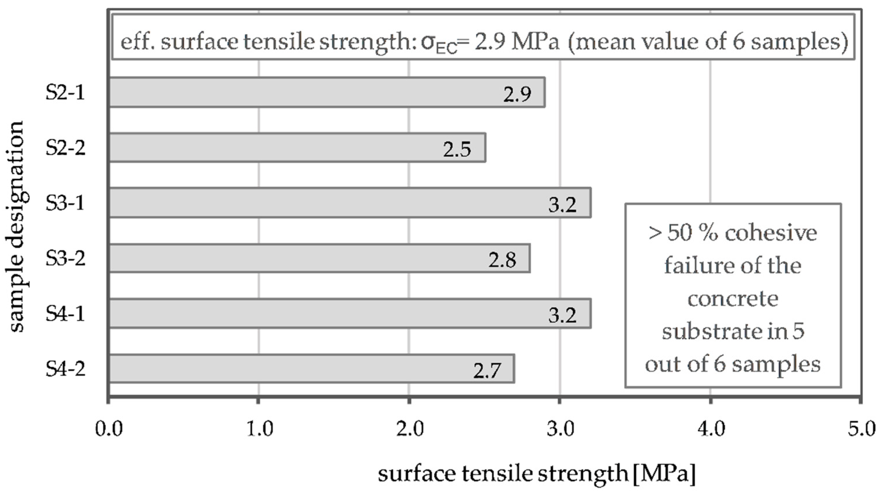
- Deutsches Institut für Normung e.V. Products and Systems for the Protection and Repair of Concrete Structures ÐTest Methods Ð Measurement of Bond Strength by Pull-Off; German Version EN 1542: 1999; Beuth Verlag GmbH: Berlin, Germany, 1999. [Google Scholar]
- Ortlepp, R. Untersuchungen zur Verbundverankerung textilbewehrter Feinbetonverstärkungsschichten für Betonbauteile. Ph.D. Thesis, Technische Universität Dresden, Dresden, Germany, 2007. [Google Scholar]


| Mixtures | M1 | M2 | Unity |
|---|---|---|---|
| Fresh concrete properties | |||
| Spreading dimension | 160 ± 12 | 165 ± 9 | [mm] |
| Fresh concrete density | 2265 | 2150 | [kg/m³] |
| Air void content | 4.9 ± 0.4 | 6 ± 0.5 | [%] |
| Hardened concrete properties | |||
| Compressive strength | 83 ± 7 | 60 ± 5 | [MPa] |
| Name | T 1C | T 2B |
|---|---|---|
| Fibre material | Carbon | Basalt |
| Coating | Acrylic/stiff | Acrylic/soft |
| Distance of the yarns 0°/90° in mm | 21.3/21.3 | 11.9/16.4 |
| Fibre area 0°/90° in mm²/m | 42.3/42.3 | 73/53 |
| Tensile strength of the yarns 1 0° in MPa | 2996 ± 174 | 936 ± 132 |
| Tensile load 1 0° in kN/m | 127 ± 7 | 68 ± 10 |
| Material Combination | First Crack Load MPa | Max. Load kN/m | Max. Tensile Strength (Textile) MPa |
|---|---|---|---|
| M1—T 1C | 3.16 ± 0.49 | 247 ± 5 | 2885 ± 62 |
| M2—T 1C | 2.63 ± 0.49 | 245 ± 7 | 2865 ± 86 |
| M2—T 2B | 3.19 ± 0.61 | 157 ± 5 | 536 ± 15 |
Publisher’s Note: MDPI stays neutral with regard to jurisdictional claims in published maps and institutional affiliations. |
© 2022 by the authors. Licensee MDPI, Basel, Switzerland. This article is an open access article distributed under the terms and conditions of the Creative Commons Attribution (CC BY) license (https://creativecommons.org/licenses/by/4.0/).
Share and Cite
Beßling, M.; Groh, M.; Koch, V.; Auras, M.; Orlowsky, J.; Middendorf, B. Repair and Protection of Existing Steel-Reinforced Concrete Structures with High-Strength, Textile-Reinforced Mortars. Buildings 2022, 12, 1615. https://doi.org/10.3390/buildings12101615
Beßling M, Groh M, Koch V, Auras M, Orlowsky J, Middendorf B. Repair and Protection of Existing Steel-Reinforced Concrete Structures with High-Strength, Textile-Reinforced Mortars. Buildings. 2022; 12(10):1615. https://doi.org/10.3390/buildings12101615
Chicago/Turabian StyleBeßling, Markus, Melanie Groh, Viola Koch, Michael Auras, Jeanette Orlowsky, and Bernhard Middendorf. 2022. "Repair and Protection of Existing Steel-Reinforced Concrete Structures with High-Strength, Textile-Reinforced Mortars" Buildings 12, no. 10: 1615. https://doi.org/10.3390/buildings12101615
APA StyleBeßling, M., Groh, M., Koch, V., Auras, M., Orlowsky, J., & Middendorf, B. (2022). Repair and Protection of Existing Steel-Reinforced Concrete Structures with High-Strength, Textile-Reinforced Mortars. Buildings, 12(10), 1615. https://doi.org/10.3390/buildings12101615