Article

Fire Resistance of an Assembled Integrated Enclosure Panel System

1
School of Civil Engineering and Architecture, Northeast Electric Power University, Jilin 132012, China
2
Northeast Electric Power Design Institute Co., Ltd. of China Power Engineering Consulting Group, Changchun 130021, China
*
Author to whom correspondence should be addressed.
Buildings 2022, 12(10), 1582; https://doi.org/10.3390/buildings12101582
Submission received: 31 August 2022 / Revised: 21 September 2022 / Accepted: 27 September 2022 / Published: 1 October 2022
(This article belongs to the Section Building Structures)

Abstract

:
Due to increasing economic development in recent years, large-scale prefabricated structures have been used for substations. However, the assembly of steel structures suffers from technical problems, such as the mismatch between the fire protection level of the main structure and the enclosure system. This paper proposes an assembled integrated enclosure panel system for covering and fireproofing steel structures, such as beams and columns, consisting of sandwich wall panels and autoclaved lightweight concrete (ALC) wall panels covering the main steel structure. Fire resistance tests were carried out for each part and the entire integrated enclosure panel system to fully investigate its fire resistance performance. ALC and gypsum were selected as the external fire protection materials for the sandwich wall panel test for theoretical analysis and fire resistance test. The fire resistance test results show that the designed solutions of sandwich wall panels and ALC panels covering steel beams and columns meet the fire protection requirements of the ISO-834 standard fire test. The proposed size scheme of the integrated enclosure panel system is an integrated sandwich wall panel composed of 50 mm thick ALC board + 50 mm thick rock wool layer + 50 mm thick ALC board and the integrated structure of 100 mm thick ALC board covering beams and columns. The designed U-shaped connectors between the wall panels are suitable for the assembled integrated enclosure panel system.

1. Introduction

Due to the increased use of prefabricated buildings, research has focused on material savings, environmental protection, and convenient construction [1,2,3]. The primary fire protection method of beams and columns of prefabricated steel structures for substations is the surface application of fire-resistant coatings or the use of fire-resistant panels [4,5,6,7]. It is challenging to ensure a seamless fireproof coating on the enclosed beam and column members and conceal the exposed main structural members [8,9]. Since the structural beams and columns consist of H-shaped steel, it is difficult to develop a fireproof layer that matches the shape of the columns and the wall. Therefore, this paper proposes an integrated enclosure system of fireproof panels for walls, beams, and columns to improve the appearance of the fabricated structure while ensuring fire resistance [10,11].
Since the last century, Western countries have conducted extensive research on composite boards. The thermal insulation materials of composite boards include calcium carbonate boards, fiber cement slate, rock wool, and styrene [12,13]. At present, for the composite sandwich wall panels, the more mature external wall panels include concrete sandwich insulation panels, steel mesh frame cement sandwich panels, ceramsite concrete composite external wall panels, and reinforced concrete thermal insulation material composite external wall panels [14,15,16].
The design of prefabricated integrated enclosure systems has focused on the enclosure of beams and columns [17]. Autoclaved lightweight concrete (ALC) panels are the most common type in Japan. ALC is a lightweight and energy-saving wall material commonly used for enclosures. The material is porous and has high thermal insulation performance, earthquake resistance, and fire resistance. It is considered green wallboard material [18,19]. Zhao et al. [20] analyzed ALC wall panels and sandwich wall panels of different densities and thicknesses and demonstrated the superiority of these materials for thermal insulation. Ozel [21] studied the optimal thickness of the thermal insulation layer under different climate conditions in the south of Elaz, Turkey, to evaluate the dynamic heat transfer. The study used ALC boards, polystyrene, and expanded polystyrene as the thermal insulation layer of the wall panel. Theoretical calculation and simulations indicated that the optimal thickness of the thermal insulation layer for this area was 2–8.2 cm. Gravit et al. [22] carried out an experimental study on steel structures using three different types of plaster to explore the fire resistance limit. The results showed that the use of plaster compositions with a density of 200 to 600 kg/m3 is optimal to ensure a higher fire resistance limit. Kosny and Christian [23] performed finite element simulations and experiments on several metal column walls. They calculated the thermal parameters of the structures using theoretical calculations and assessed the thermal insulation performance of the walls. Pancheti and Mahendran [24] analyzed the fire resistance of a light steel frame covered with AAC wall panels. The results showed that the fire resistance limit of the AAC wall panel was 204 min under load-bearing and 240 min under non-load-bearing conditions. Jiang and Wu [25] evaluated commonly used materials in fireproof steel structures and selected three materials, including ALC panels.
There are currently no size recommendations for wall panel enclosure systems of steel structures; thus, further research is required. In addition, the installation of the external wall panel system of the traditional substation requires the installation of light steel keels in advance, and then the wall panels are assembled. It cannot be prefabricated and modularized, and the efficiency is relatively low.
We developed a wall panel system for the protection of the main steel structure of the substation which is highly modular and can be prefabricated in the factory in advance. Integrated light steel keel and wall panel materials can be assembled directly on site, avoiding wet work. In this study, ALC was selected as the experimental material of an enclosure wall panel system, and a gypsum board was added to the sandwich wall panel as the control in the experiment. A fire resistance test was conducted using an integrated enclosure system composed of a single-frame steel structure frame covered by ALC panels and sandwich wall panels to determine whether the fire resistance limit of the wall panel and beam-column structure meets the requirements of the standard. A size recommendation for the assembled integrated enclosure panel system is provided. The assembled integrated enclosure panel system has been patented by our team and is planned to be used in the construction of many large substations in Hangzhou, China [26]. Therefore, before the practical engineering application, it is necessary to evaluate the fire resistance and theoretical research of the system.

2. Experimental Program

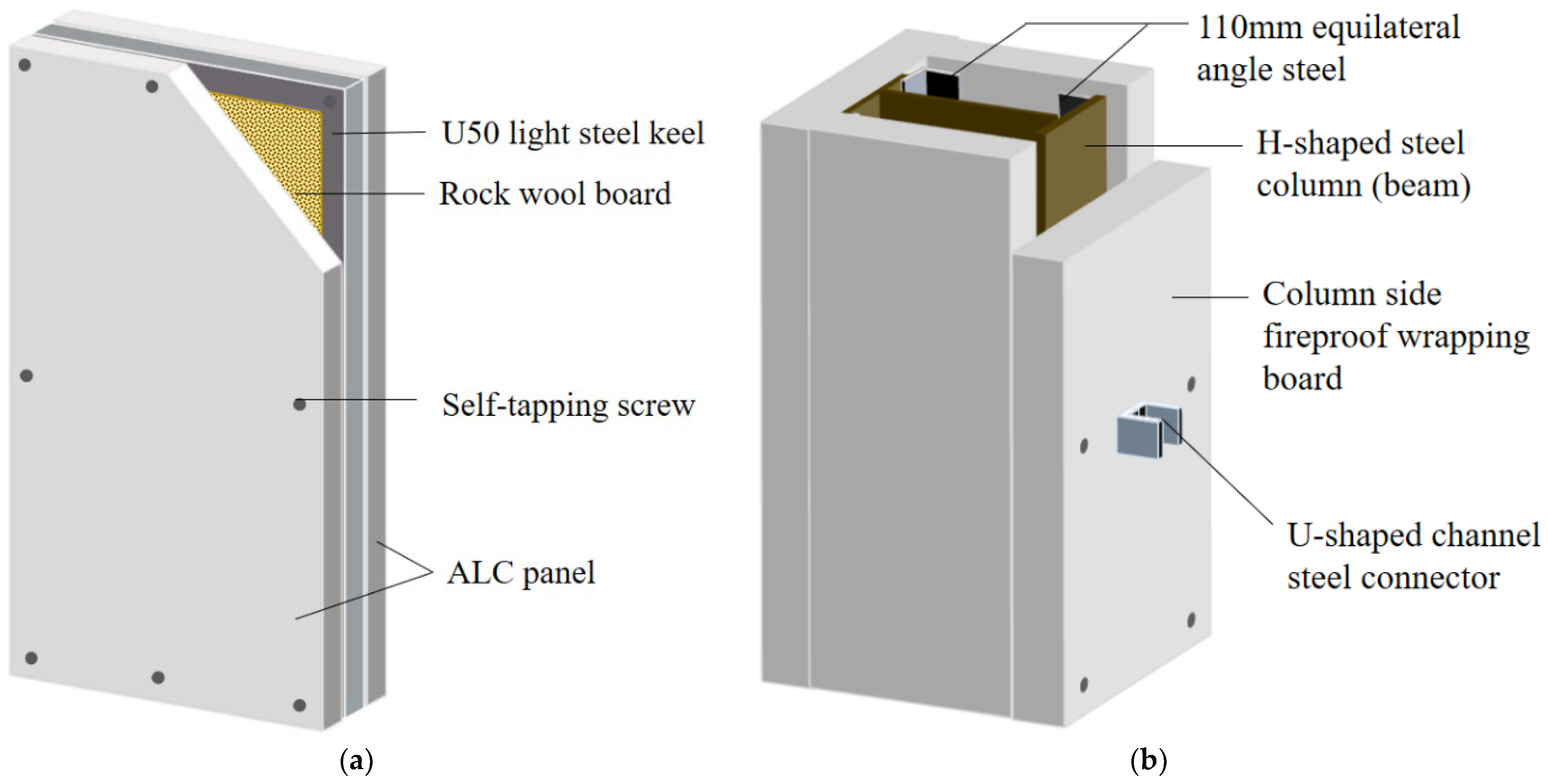
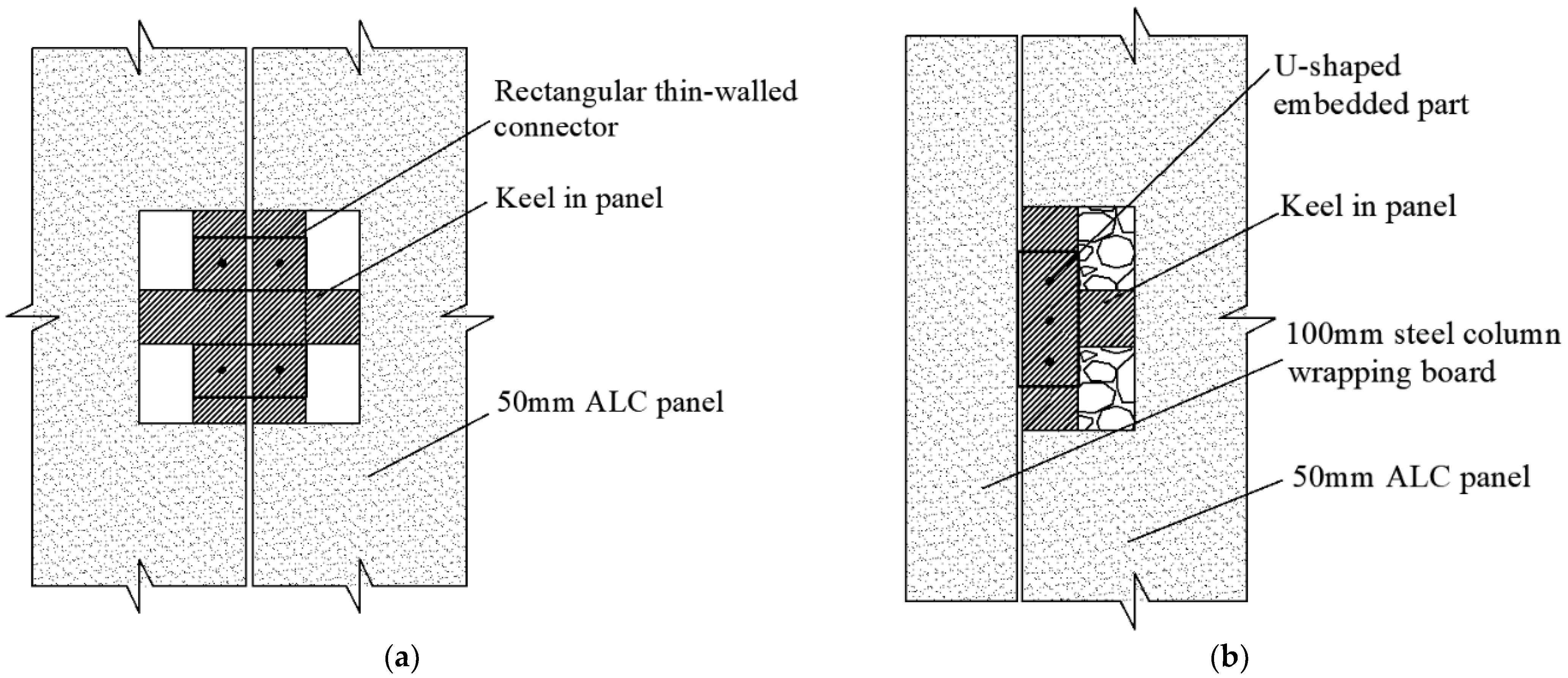
2.1. Enclosure System

The proposed enclosure system is highly modular and well suited for prefabricated buildings. ALC was selected as the material for the sandwich wall panel, as shown in Figure 1a. The ALC panels were used as a fireproof cover for the steel beams and steel columns to create an integrated enclosure system. All panels in the system were connected by novel connectors to meet the standard and enclose the system, as shown in Figure 1b. The wall panel has high aesthetic value and is fire resistant and easy to install [27,28].

2.2. Specimen Design

The sandwich wall panel consists of two ALC panels on the outside and an insulation layer on the inside. The inner keel frame in the thermal insulation layer is made of U50 light steel keel, and the remainder is filled with rock wool. The dimensions of the ALC panel are 1900 × 600 × 50 mm. The dimensions of the U50 light steel partition wall keel are 50 × 40 × 0.6 mm, and the rock wool insulation board has a density of 120 kg/m3. The total thickness of the ALC composite wall panel is 150 mm, and its weight is about 85 kg. The light steel keel is connected to the inner and outer ALC panels by 7 cm self-tapping screws, and the horizontal and vertical light steel keels are connected with 3 cm self-tapping screws. The sandwich wall panel structure diagram is shown in Figure 2.
The installation process of the integrated enclosure wall panel proceeds from top to bottom, and the size of the wall panel can be adapted to the size of the building. The construction is quick and simple. We used two types of wall panels in the fire resistance test (Table 1). The ALC sandwich wall panel was denoted as A, and the quantity is two (named A1, A2).
Since gypsum is a flame-retardant material that is lightweight and has low cost, a sandwich wall panel composed of gypsum boards was fabricated and denoted as B. This sandwich wall panel consisted of two 12 mm thick paper-faced gypsum boards with a center of U75 light steel keel and a 75 mm thick rock wool insulation layer. The length and width of panels A and B were the same. The on-site assembly of the sandwich wall panels is shown in Figure 3.
The beam and column were completely covered by the ALC fireproof board to protect the beam and column. The seams between the wallboards were sealed with fireproof cement and covered by an ALC plate to ensure fire resistance. All surfaces were covered by the same material to ensure a high aesthetic value and seamless coverage, as shown in Figure 4.
As a simple and efficient connection between the wallboard and the beam-column, U-shaped steel sheets were embedded on the sidewall of the beam-column panel to connect the panels with self-tapping screws. Two 5 × 10 cm rectangular openings were cut into the panel, exposing the light steel keel frame to insert the U-shaped thin-wall channel steel, and self-tapping screws were used to connect the components, as shown in Figure 5. After connecting, the opening was filled with ALC panels again.

2.3. Equipment and Test Procedures

The fire-resistant test furnace at the Liaoning Provincial Product Quality Supervision and Inspection Institute was used in the experiment. The test device is shown in Figure 6. The heating curve based on the international standard ISO-834 [29] was used in the simulation to measure the temperature of the wall panels, beams, and columns. Only one side of the structure was exposed to fire, and the test was conducted at room temperature without loading. The standard heating curve is defined as follows:
T(t) = 345 lg (8t + 1) + 20,
where t is the time from the start of the test in minutes (min); T is the average temperature inside the furnace in degrees Celsius (°C).

2.3.1. Fire Resistance Test of the ALC Sandwich Wall Panel (Denoted as Test M)

A fire resistance test of the sandwich wall panel was carried out. The fire resistance test lasted 1 h. The layout of the temperature measuring points of sandwich wall panels A and B is shown in Figure 7.

2.3.2. Fire Resistance Test of the Integrated ALC Panel System (Denoted as Test N)

The temperature measurement points for the fire resistance tests of the beams and columns were laid out in accordance with the thermocouple layout requirements for steel beams and columns in the Chinese standard specifications ”Fire-resistance tests-Elements of building construction-Part 6: Specific requirements for beams” [30] and ”Fire-resistance tests-Elements of building construction-Part 7: Specific requirements for columns” [31] (Figure 8). The thermocouples were evenly in the vertical direction at appropriate distances and did not conflict with the thermocouple in the furnace.
  • Fire resistance test of a single steel frame covered by ALC panels (denoted as test N(1)).
The fire resistance test lasted 3 h. The purpose was to study the fire resistance of the H-shaped steel columns and H-shaped steel beams covered with the ALC panel without a sandwich wall panel. Therefore, the layout of the temperature measuring points was more complex than in the fire resistance test of the integrated enclosure system covered by ALC panels. We measured the temperature on all sections of the H-shaped steel beams and H-shaped steel columns. The thermocouple locations are shown in Figure 8.
  • Fire resistance test of the integrated enclosure system covered by ALC panels (denoted as test N(2)).
The fire resistance test lasted 1 h. The objective was to determine whether the connections between the ALC sandwich wall panels and the beam and column covered by the ALC panels were damaged or became unstable. Therefore, the temperature measurement points were located in the middle of the steel beam and the steel column and were used as reference data. The conditions of the wall panels and connectors after the test were determined. The thermocouple locations are shown in Figure 9.
The measurement points U1, U2, and U3 were located in the center of the fire surface of the sandwich wall panel, and point U4 was located in the center of the H-shaped column web. Point U5 was located in the center of the H-beam web. The morphological change of the connector after exposure to fire was determined.

3. Results and Discussion

3.1. Theoretical Calculation

Since the effect of the sandwich wall panel is improved compared with the pure material wall panel, the theoretical calculation was carried out for the design scheme of the sandwich wall panel (panels A, B). An important indicator to measure the suitability of wallboard is its thermal performance. In addition, the sandwich wall panel also has low self-weight characteristics. It is not only convenient for transportation and hoisting but can also reduce the construction quality. Therefore, the parameter comparison between the sandwich wall panel and the pure concrete wall panel of the same material was conducted through theoretical calculation.
The heat transfer coefficient is an important index to measure the thermal performance of the exterior wall. In order to facilitate the analysis of parameters, 150 mm ALC wallboard and 99 mm gypsum wallboard with the same thickness as the composite sandwich wall panel (panels A, B) were selected for comparison. According to ”Code for Thermal Design of Civil Buildings” [32], the heat transfer coefficient of sandwich wall panels composed of multi-layer materials can be calculated by the following relations (2). The non-uniform layer and thermal bridge effect composed of light steel keel and rock wool were corrected and converted, and the material parameters of each structural layer are shown in Table 2.
K = 1 R i + i = 1 n δ i λ i α i + R e ,
where K is the external wall heat transfer coefficient in W/(m2·K); δi is the thickness of each structural layer of the wall panel in meters; λi is the material thermal conductivity in W/(m·K); αi is the material thermal conductivity correction factor; Ri is the inner surface heat transfer resistance, which is taken as 0.11 m2·K/W; and Re is the external surface heat transfer resistance, which is taken as 0.04 m2·K/W.
The data obtained after calculation are shown in Table 3. It can be seen that the thermal conductivity of panel A is reduced by 30.3%, and the weight is reduced by 21.2% compared with the pure material wall panel. Compared with the pure material wall panel, the thermal conductivity of panel B solution is reduced by 69.2%, and the weight is reduced by 62.8%. This leads to not only increased fire resistance but also lightweight and convenient on-site construction. The combined performance of the two sandwich wall panel designs needs to be evaluated comprehensively with test results and thermal analysis.

3.2. Visual Observations

3.2.1. Results of Test M

During the Test

(1) After panel A was exposed to the fire for 12 min, white smoke appeared at the top of the structure, and a small amount of white smoke appeared between the sintered brick and the frame connection. After 29 min, the thermal insulation mortar between the test wall panels changed from light gray to milky white, and a few vertical cracks were generated. The thermal insulation mortar near the middle was ruptured, and the mortar between the test wall panels cracked in the longitudinal direction. The surface of the panel maintained its thermal insulation performance, and no destructive cracks or color changes were observed.
(2) After panel B was exposed to the fires for 8 min, a small amount of white smoke appeared on the top of the structure. Some white smoke was observed at the joint between the sintered brick on the left side of the structure and the steel frame after 10 min. A pungent odor was noticed after 29 min. After 40 min, the thermal insulation mortar between the test wall panels changed from light gray to white-gray, and a large number of vertical cracks were generated. The surface maintained its thermal insulation performance, and no penetrating damage was observed. After 48 min, the center of the gypsum panel changed from white to yellow and continued to black. This position corresponded to the light steel keel position of the sandwich layer.

After the Test

(1) The fire surface of the ALC panel (panel A) and its parts after the test are shown in Figure 10a. It was observed that the internal keel frame and rock wool of the sandwich wall panel had not changed significantly, and the light steel keel frame was not deformed (the deformation of the steel keel in Figure 10b is caused by disassembly after the test). The rock wool board in the wall panel was not carbonized, and the self-tapping screws connecting the light steel keel and the ALC wall panel were not deformed.
The test results showed that the fire surface of the ALC sandwich wallboard exhibited excellent integrity. There was no damage to the fire surface of the specimen under high temperature, the color did not change, and no cracks had formed. The highest temperature and the fastest increase in the temperature occurred near the upper side of the furnace because this area was closest to the flame on both sides of the test furnace. However, because the thermal conductivity of the ALC panel is very low, the average temperature of the specimen did not rise rapidly.
(2) In contrast, after panel B was exposed to the fire for 1 h, the gypsum board on the fire side of the specimen was completely burnt and peeled off, and the gypsum had lost its protective ability. The light steel keel and rock wool in the plate at the center of the specimen were completely destroyed, and the light steel keel had changed from bright silver to black and was deformed. The rock wool board had lost its thermal insulation ability, and part of it was carbonized and hardened. The self-tapping screws connecting the light steel keel to the gypsum board were deformed. The gypsum board exhibited destructive cracks, and part of the material had fallen off after it lost its supporting capacity. The schematic diagram of the specimen after the exposure to fire is shown in Figure 11.

3.2.2. Results of Test N

The first group of tests of the integrated ALC panel system was a fire resistance test of the single-frame steel frame covered by the ALC fireproof panel (test N(1)); the test duration was 3 h. About 10 min after the start of the test, white smoke emerged from the lower part of the H-shaped steel beam, and an odor was generated. At the beginning of the test, the results were the same as in the previous experiment, i.e., we noticed a smell of burning wood and a lot of white smoke. The color of the H-shaped steel beam and steel column did not change at the beginning of the test. No color changes in the H-shaped steel beam or steel column were observed from about 90 min to the end of the test, and there were only a few cracks on the fire surface of the ALC panels. The seal between the plate seams of the test specimen was also intact, and no fire leakage occurred.
The second group of tests was the fire resistance test of the integrated ALC panel system (test N(2)); the test duration was 1 h. After 7 min, white smoke emerged from the lower part of the H-shaped beam, accompanied by a pungent odor. After 10 min, the smell of burning wood was intense. The reason was that several wood cushion blocks were tightly fit within the frame in the upper part so that the structure was closely connected to the steel frame. After 30 min, the structure did not exhibit further change, but white smoke continued to leak from the upper part of the frame.
After being exposed to the fire for 1 h, the sandwich wall panel in the middle of the structure was removed, and the testers entered the test furnace to observe the morphological changes in the specimen’s fire surface. There were no cracks on the fire surface ALC panel, and the color had not changed. The filling between the plate seams of the test specimen was intact, and no fire leakage occurred.
The fire resistance limit of the steel beams and steel columns was based on the ”Fire-resistance tests-Elements of building construction-Part 1: General requirements” [33]. The fire resistance limit of steel beams is 2 h, and that of the columns is 3 h. Within the time range of the fire resistance limits, the steel beams and steel columns in this test did not suffer from instability of collapse, and the final temperature of the beams and columns did not exceed 100 °C. The maximum deformation of the steel beam was 39 mm <L/20, and the axial deformation of the steel column was 10 mm <h/100, meeting the requirements of the specification.

3.3. Thermal Analysis

The temperature–time (T-t) curves at the measurement points of the ALC sandwich wall panels (panels A1 and A2) and the gypsum sandwich wall panel (panel B) after being exposed to fire for 1 h are shown in Figure 12. The abscissa is the heating time t, and the ordinate is the temperature T. The T-t curves show that the temperature at all measurement points of the components increases with the heating time. The temperature of the fire surface of the wall panel slowly rises. The maximum temperature of the ALC composite wall panel is 45.6 °C at R7, and this value is much smaller than the maximum temperature of the gypsum sandwich wall panel measuring point, which is 105.2 °C. The average temperature of all measurement points on the fire surface after 1 h fire does not exceed 180 °C, meeting the requirements of the specification.
The temperature is affected by the position of the flame nozzle of the test furnace and the distance between the components and the fire center. It is challenging to achieve uniform heating. Therefore, the temperature measurement points R3 and Q3 at the center of the test wall panel were selected for analysis; the temperature curves of these points are shown in Figure 13.
The ALC sandwich wall panel exhibits better temperature performance than the gypsum panel. The temperature at the center does not exceed 50 °C, and the temperature increases over time. Because the thermal conductivity of the fire-exposed ALC sheet is very low, the temperature transfer rate of the fire-exposed wall panel is slow, so the temperature of panels A1 and A2 remain basically unchanged at the beginning of the test. After being exposed to fire for 35 min, the temperature of the unfired surface of the specimen began to rise slowly. The rate of temperature rise began to increase significantly. Among them, the temperature of the R7 measuring point is too high, because the measuring point is closest to the flame nozzle in the furnace, and there is uneven heating. After the experiment, the average temperatures of panel A1 and A2 were 40.1 and 42.4 °C, respectively.
The temperature of the gypsum sandwich wall panel rose faster, panel B was damaged after being exposed to the fire for 20 min, and the rock wool was exposed to the fire. Because rock wool is a non-combustible material and its thermal conductivity is low, the temperature of the gypsum panel remains stable. After burning for 40 min, the rock wool is carbonized, decreasing its thermal insulation capacity, and resulting in a gradual increase in the temperature of the gypsum panel. The thickness of the insulation layer is inversely proportional to the temperature of the surface. The thicker the insulation layer, the lower the temperature of the surface. After the experiment, the average temperature of the measuring point of panel B is 67.8 °C.
Therefore, according to the test results of the two kinds of composite sandwich wall panels A and B, both kinds of wall panels meet the specification requirements and can be put into use. However, the surface of gypsum sandwich wall panel is seriously damaged after fire, and the fire protection effect of the ALC material solution is improved. Therefore, it is suggested that gypsum sandwich wall panel can be used as a non-load-bearing inner partition of a house. The ALC sandwich wall panel can be used as the exterior wall panel of the house, and the panel A scheme was adopted in the subsequent test of the enclosure wall panel system.
The T-t curves of tests N(1) and N(2) are shown in Figure 14. In test N(1), the duration of exposure to the fire is 3 h. The column was protected by the ALC plate on the fire surface in the first 50 min of the test, and the temperature remained unchanged. After 50 min, the rate of increase at the measuring point under the column is lower than that of the upper measuring point, which is caused by the high temperature in the upper part of the furnace, but the temperature difference is very small. After the test, the average temperature of the measuring points at the position of the steel column was 42.9 °C, and the average temperature of the measuring points at the position of the steel beam was 65.8 °C. The highest temperature occurs at P15, which is located in the upper part of the right flange of the H-shaped beam, as shown in Figure 14a. Therefore, the 100 mm thick ALC panel exhibited good fire resistance and protected the steel beams and steel columns.
In test N(2), the temperature shows a similar rising trend at U1, U2, and U3 on the wall panel. The temperatures at the points of the H-shaped steel column showed a slow upward trend because point U4 is located in the middle of the H-shaped steel column and far away from the fire source in the furnace. Therefore, the temperature did not increase as fast as that of the H-shaped steel beam temperature. However, the temperature at U5 of the H-shaped steel beam rose at a uniform speed. The reason for this phenomenon is the uneven temperature distribution in the furnace, which causes a higher temperature in the middle part of the upper layer of the structure than in other parts.
The U1, U2, and U3 curves in Figure 14b indicate that the temperature of the sandwich wall panel after being exposed to the fire for 1 h was close to that of the test specimens A1 and A2 in test M. The only difference between the parts of the sandwich wall panels in these two tests was that rectangular notches were located on both sides and the lateral connectors in test N(2). The filling of the seams did not cause a large temperature difference, indicating that this connection type did not affect the fire resistance of the integrated enclosure wall panel system.
Prefabricated substations and other enclosed frame structures do not bear a large load. For the substation building, if a thicker ALC board is selected, the cost and space are increased. Therefore, for the thickness of the ALC sheet wrapped by the main steel structure, the 100 mm commonly used by manufacturers was selected. The experimental results and thermal analysis demonstrated that the integrated enclosure system exhibited excellent fire resistance. The temperature of all measuring points did not exceed 100 °C, and there was no buckling or damage. The results showed that the double-layer sandwich wall panel consisting of the 50 mm ALC panel + a 50 mm rock wool layer + a 50 mm ALC panel and the main structure with a 100 mm ALC panel covering the beam and column met the fire resistance requirements of the ISO-834 standard fire test. Thus, this enclosure system is suitable for practical applications.

3.4. Beam-Column Connector

The test wall panels were connected with the light steel keel by the U-shaped connecter. The ALC plate filling the notch was removed, and the failure mode of the connector after the fire was observed. The panel connectors and U-shaped connectors after the exposure to fire are shown in Figure 15. The connectors were not damaged, and the steel and self-tapping screws were not deformed. Through the comparison of the T-t curves of the sandwich wall panels in tests M and N(2), it could be seen that the U-shaped connectors did not affect the integrity of the wall panel system and successfully played multiple roles of fire protection and connection. These results showed that the selected connectors were adequate and could withstand exposure to fire for 1 h. Thus, they are suitable for use in prefabricated building enclosures.

4. Conclusions

This work analyzed the fire resistance performance of prefabricated ALC panels covering beams and columns. The thermal insulation performance of the ALC panels was calculated, and a fire resistance test was carried out. An integrated ALC panel system was designed to increase the integrity of the structure, improve its fire resistance, shorten the construction period, and enable the use of prefabricated panels to simplify the on-site installation. The conclusions of this paper are as follows:
(1) Theoretical calculations were carried out for two kinds of sandwich wall panels from the perspectives of heat transfer and self-weight, and fire resistance experiments were carried out. The results of the fire resistance experiment showed that both types of sandwich panels (ALC panels or gypsum boards with a light steel keel core) met the requirements of the specification. The temperature of the fire surface of the wall panel decreased with an increase in the thickness of the wall panel. The double-sided 50 mm thick ALC wall panel + 50 mm thick insulation layer sandwich wall panel scheme can be used as a component of the assembled integrated enclosure panel system, and the gypsum sandwich wall panel can be used as a non-load bearing interior partition board.
(2) The proposed integrated enclosure system and the panel connectors and U-shaped connectors were not damaged, the steel did not bend, and the self-tapping screws were not deformed after being exposed to the fire for 1 h. In addition, the T-t curves obtained from the fire resistance tests of the sandwich wall panel and the integrated system were consistent, indicating that the connectors did not affect the fire resistance of the structure and can be used in practical applications.
(3) The proposed ALC-based enclosure system met the requirements of fire protection and decoration. The 100 mm thick ALC wrapping plate was selected for the beam and column. When the steel beam and the steel column were not loaded, the temperature did not reach 100 °C, and no deformation occurred; thus, the system protected the beam and column. The proposed size scheme of the integrated enclosure panel system is the integrated sandwich wall panel composed of 50 mm thick ALC board + 50 mm thick rock wool layer + 50 mm thick ALC board and the integrated structure of a 100 mm thick ALC board covering beams and columns. The proposed enclosure panel system meets the fire resistance requirements of the ISO-834 standard fire test and is suitable for practical engineering.

5. Patents

“A wrapped enclosure structure system suitable for fabricated substations” has been patented by our team (CN111749509B).

Author Contributions

Conceptualization, C.Z.; methodology, Z.W.; software, J.C.; validation, D.W.; writing—original draft preparation, Z.W. and J.C.; writing—review and editing, Z.W. and D.W.; supervision, C.Z. All authors have read and agreed to the published version of the manuscript.

Funding

This research was funded by the State Grid Zhejiang Electric Power Co., Ltd. and the Collective Enterprise Science and Technology Project: Research and Application of Key Technologies for Modular Construction of Prefabricated Substations (STGYHT/18-JS-206).

Data Availability Statement

The data presented in this study are available in the article.

Conflicts of Interest

The authors declare no conflict of interest.

References

  1. Yang, B.; Liu, B.; Xiao, J.; Zhang, B.; Wang, Z.; Dong, M. A novel construction scheduling framework for a mixed construction process of precast components and cast-in-place parts in prefabricated buildings. J. Build. Eng. 2021, 43, 103181. [Google Scholar] [CrossRef]
  2. Tumminia, G.; Guarino, F.; Longo, S.; Ferraro, M.; Cellura, M.; Antonucci, V. Life cycle energy performances and environmental impacts of a prefabricated building module. Renew. Sustain. Energy Rev. 2018, 92, 272–283. [Google Scholar] [CrossRef]
  3. Yuan, Z.; Sun, C.; Wang, Y. Design for Manufacture and Assembly-oriented parametric design of prefabricated buildings. Autom. Constr. 2018, 88, 13–22. [Google Scholar] [CrossRef]
  4. Fateh, T.; Guillaume, E.; Joseph, P. An experimental study of the thermal performance of a novel intumescent fire protection coating. Fire Saf. J. 2017, 92, 132–141. [Google Scholar] [CrossRef]
  5. Corlay, C.; Advani, S. Temperature distribution in a thin composite plate exposed to a concentrated heat source. Int. J. Heat Mass Transf. 2007, 50, 2883–2894. [Google Scholar] [CrossRef]
  6. Salhab, B.; Wang, Y. Equivalent thickness of cold-formed thin-walled channel sections with perforated webs under compression. Thin Wall Struct. 2008, 46, 823–838. [Google Scholar] [CrossRef]
  7. Feng, M.; Wang, Y. An analysis of the structural behaviour of axially loaded full-scale cold-formed thin-walled steel structural panels tested under fire conditions. Thin Wall Struct. 2005, 43, 291–332. [Google Scholar] [CrossRef]
  8. Salhab, B.; Wang, Y. A study of the thermal performance of cold-formed thin-walled perforated steel studs (thermal studs) in fire. In Proceedings of the Ninth Biennial Conference on Engineering, Construction, and Operations in Challenging Environments, Houston, TX, USA, 7–10 March 2004; pp. 688–695. [Google Scholar] [CrossRef]
  9. Feng, M.; Wang, Y.-C. An experimental study of loaded full-scale cold-formed thin-walled steel structural panels under fire conditions. Fire Saf. J. 2005, 40, 43–63. [Google Scholar] [CrossRef]
  10. Kolarkar, P.; Mahendran, M. Experimental studies of gypsum plasterboards and composite panels under fire conditions. Fire Mater. 2014, 38, 13–35. [Google Scholar] [CrossRef] [Green Version]
  11. Ricardo, A.S.; de Santana Gomes, W.J. Structural Reliability Methods Applied in Analysis of Steel Elements Subjected to Fire. J. Eng. Mech. 2021, 147, 04021108. [Google Scholar] [CrossRef]
  12. Chen, W.; Ye, J.; Li, X. Thermal behavior of gypsum-sheathed cold-formed steel composite assemblies under fire conditions. J. Constr. Steel Res. 2018, 149, 165–179. [Google Scholar] [CrossRef]
  13. Dias, Y.; Keerthan, P.; Mahendran, M. Fire performance of steel and plasterboard sheathed non-load bearing LSF walls. Fire Saf. J. 2019, 103, 1–18. [Google Scholar] [CrossRef]
  14. Liu, Q.; Du, W.; Uddin, N.; Zhou, Z. Flexural Behaviors of Concrete/EPS-Foam/Glass-Fiber Composite Sandwich Panel. Adv. Mater. Sci. Eng. 2018, 2018, 5286757. [Google Scholar] [CrossRef] [Green Version]
  15. O’Hegarty, R.; Reilly, A.; West, R.; Kinnane, O. Thermal investigation of thin precast concrete sandwich panels. J. Build. Eng. 2020, 27, 100937. [Google Scholar] [CrossRef]
  16. Hodicky, K.; Sopal, G.; Rizkalla, S.; Hulin, T.; Stang, H. Experimental and numerical investigation of the FRP shear mechanism for concrete sandwich panels. J. Compos. Constr. 2015, 19, 04014083. [Google Scholar] [CrossRef] [Green Version]
  17. Steau, E.; Mahendran, M. Elevated temperature thermal properties of fire protective boards and insulation materials for light steel frame systems. J. Build. Eng. 2021, 43, 102571. [Google Scholar] [CrossRef]
  18. Ng, S.-C.; Low, K.-S. Thermal conductivity of newspaper sandwiched aerated lightweight concrete panel. Energy Build. 2010, 42, 2452–2456. [Google Scholar] [CrossRef]
  19. Ng, S.-C.; Low, K.-S.; Tioh, N.-H. Thermal inertia of newspaper sandwiched aerated lightweight concrete wall panels: Experimental study. Energy Build. 2011, 43, 2956–2960. [Google Scholar] [CrossRef]
  20. Zhao, Z.; Yang, X.; Qu, X.; Zheng, J.; Mai, F. Thermal insulation performance evaluation of autoclaved aerated concrete panels and sandwich panels based on temperature fields: Experiments and simulations. Constr. Build. Mater. 2021, 303, 124560. [Google Scholar] [CrossRef]
  21. Ozel, M. Thermal performance and optimum insulation thickness of building walls with different structure materials. Appl. Therm. Eng. 2011, 31, 3854–3863. [Google Scholar] [CrossRef]
  22. Gravit, M.; Shabunina, D.; Antonov, S.; Danilov, A. Thermal Characteristics of Fireproof Plaster Compositions in Exposure to Various Regimes of Fire. Buildings 2022, 12, 630. [Google Scholar] [CrossRef]
  23. Kosny, J.; Christian, J.E. Thermal evaluation of several configurations of insulation and structural materials for some metal stud walls. Energy Build. 1995, 22, 157–163. [Google Scholar] [CrossRef]
  24. Pancheti, J.; Mahendran, M. Fire resistance of external light gauge steel framed walls clad with autoclaved aerated concrete panels. Thin Wall Struct. 2021, 167, 108201. [Google Scholar] [CrossRef]
  25. Jiang, S.; Wu, H. An experimental investigation on the fire resistance of the integrated envelope-fire protection material for steel buildings. Prog. Steel Build. Struct. 2021, 23, 77–84. [Google Scholar] [CrossRef]
  26. Sheng, X.; Yu, R.; Yang, X.; Pan, S.; Xu, Q.; Xu, P.; Chen, J.; Jin, C.; Ji, X.; Wei, L.; et al. A Wrapped Enclosure Structure System Suitable for Fabricated Substations. CN111749509B, 15 March 2022. (In Chinese). [Google Scholar]
  27. Ye, J.; Chen, W.; Wang, Z. Fire-resistance behavior of a newly developed cold-formed steel composite floor. J. Struct. Eng. 2017, 143, 04017018. [Google Scholar] [CrossRef]
  28. Wang, Y.; Foster, A. Experimental and numerical study of temperature developments in PIR core sandwich panels with joint. Fire Saf. J. 2017, 90, 1–14. [Google Scholar] [CrossRef]
  29. ISO-834; Fire Resistance Tests-Elements of Building Construction. ISO-834-1. ISO: Geneva, Switzerland, 1999.
  30. GB/T 9978.6-2008; Fire-Resistance Tests-Elements of Building Construction-Part 6: Specific Requirements for Beams. SAC: Beijing, China, 2008. (In Chinese)
  31. GB/T 9978.7-2008; Fire-Resistance Tests-Elements of Building Construction-Part 7: Specific Requirements for Columns. SAC: Beijing, China, 2008. (In Chinese)
  32. GB 50176.1-2016; Code for Thermal Design of Civil Buildings. SAC: Beijing, China, 2016. (In Chinese)
  33. GB/T 9978.1-2008; Fire-Resistance Tests-Elements of Building Construction-Part 1: General Requirements. SAC: Beijing, China, 2008. (In Chinese)
Figure 1. The prefabricated integrated enclosure panel system consisting of part (a) and part (b).
Buildings 12 01582 g001
Figure 2. The structure of the sandwich wall panel.
Buildings 12 01582 g002
Figure 3. Fabrication of the sandwich wall panel: (a) assembled insulation layer; (b) self-tapping screw connection at the edge.
Buildings 12 01582 g003
Figure 4. Plan view of the H-shaped steel beam-column covered by the ALC wall panels.
Buildings 12 01582 g004
Figure 5. Connections between the parts: (a) between sandwich panels; (b) between sandwich wall panels and the beam (column).
Buildings 12 01582 g005
Figure 6. Refractory test furnace.
Buildings 12 01582 g006
Figure 7. Layout of the temperature measuring points on the wall panels.
Buildings 12 01582 g007
Figure 8. Temperature measuring points in the fire resistance test of the H-shaped steel (a) column and (b) beam.
Buildings 12 01582 g008
Figure 9. Layout of temperature measuring points in the fire resistance test of the integrated enclosure system.
Buildings 12 01582 g009
Figure 10. Fire surface (a) and sandwich insulation (b) of ALC sandwich wall panels after fire test.
Buildings 12 01582 g010
Figure 11. Fire surface (a) and sandwich insulation (b) of gypsum sandwich wall panels after fire test.
Buildings 12 01582 g011
Figure 12. T-t curve at the measurements points of test M: (a) panel A1; (b) panel A2; (c) panel B.
Buildings 12 01582 g012
Figure 13. T-t curves of measurement point R3 and Q3 at the center of the wall panel.
Buildings 12 01582 g013
Figure 14. T-t curves at the measurement points of test N: (a) test N(1); (b) test N(2).
Buildings 12 01582 g014
Figure 15. The panel connectors (a) and U-shaped connectors (b) after fire test.
Buildings 12 01582 g015
Table 1. Name and dimensions of the specimens used in the fire resistance test of the wall panel.
No.Specimen NameWall Panel Size
A50 mm double-sided ALC + U50 light steel keel sandwich wall panel1.9 × 0.6 × 0.15 m
B12 mm double-sided plaster + U75 light steel keel sandwich wall panel1.9 × 0.6 × 0.099 m
Table 2. Material parameters of each structural layer.
ProjectDensity, kg/m3λi, W/(m·K)αi
ALC panel5500.141.15
Gypsum panel10500.331.10
Steel785054.001.00
Rock wool1300.051.20
Table 3. Comparison of heat transfer coefficient and self-weight of wall panels.
Wall Panel MaterialK1, W/(m2·K)K2, W/(m2·K)M1, kgM2, kg[K2 − K1/K2], %[M2 − M1/M2], %
ALC 0.6440.92474.1194.0530.321.2
Gypsum0.7322.37344.12118.5069.262.8
where K1 is the heat transfer coefficient of composite sandwich wall panels; K2 is the heat transfer coefficient of pure material wall panels; M1 is the mass of composite sandwich wall panels; and M2 is the mass of pure material wall panels.
Publisher’s Note: MDPI stays neutral with regard to jurisdictional claims in published maps and institutional affiliations.

