
Multi-Disciplinary Characteristics of Double-Skin Facades for Computational Modeling Perspective and Practical Design Considerations


Abstract
1. Introduction
2. A Need for Better Envelope Performance
3. Study Methodology
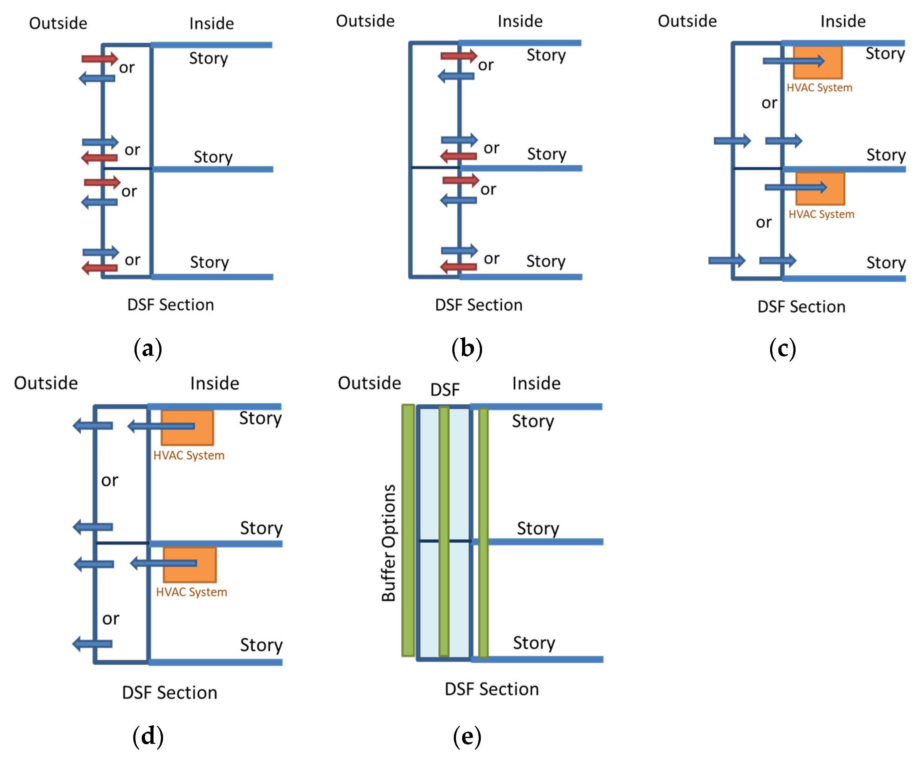
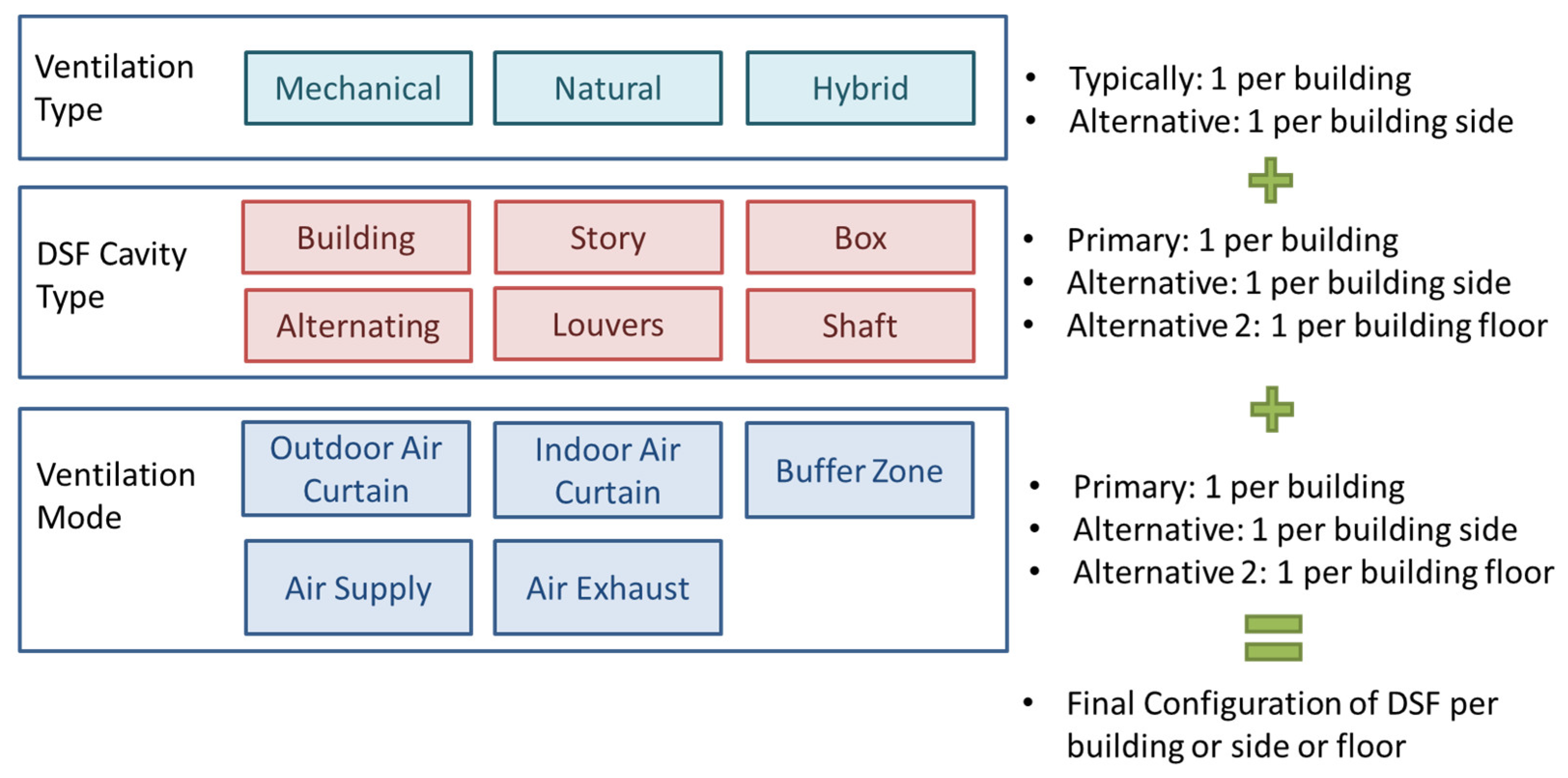
4. DSF System Types and Configurations
Designer Takeaways on Types and Configurations
5. DSF Glazing
5.1. Glazing Types
5.2. Structural Glazing and Support Materials
5.3. Glazing Properties for Design
5.4. Designer Takeaways on Glazing
6. DSF Structural Support and Construction Assembly
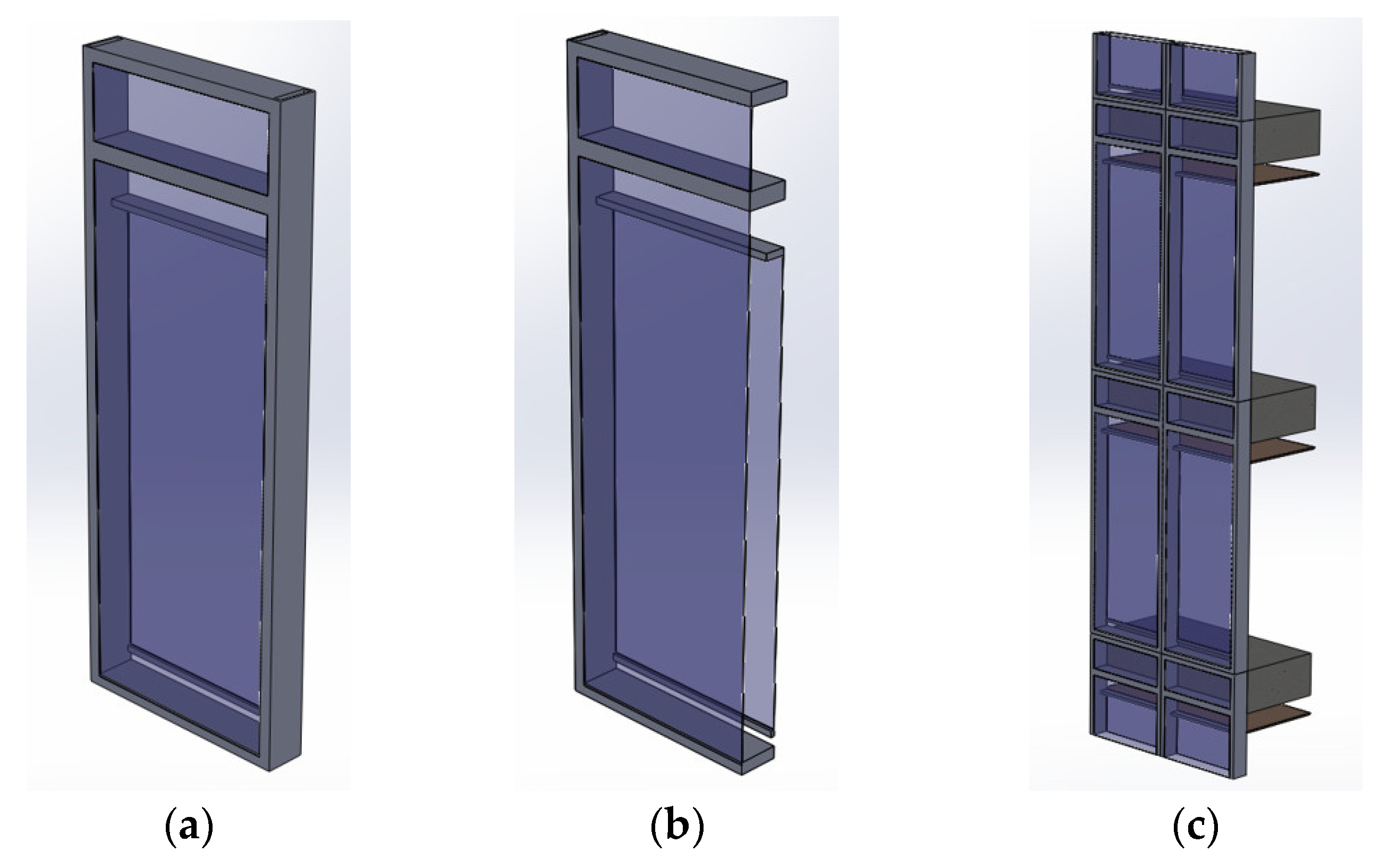
6.1. DSF Unitized Composition
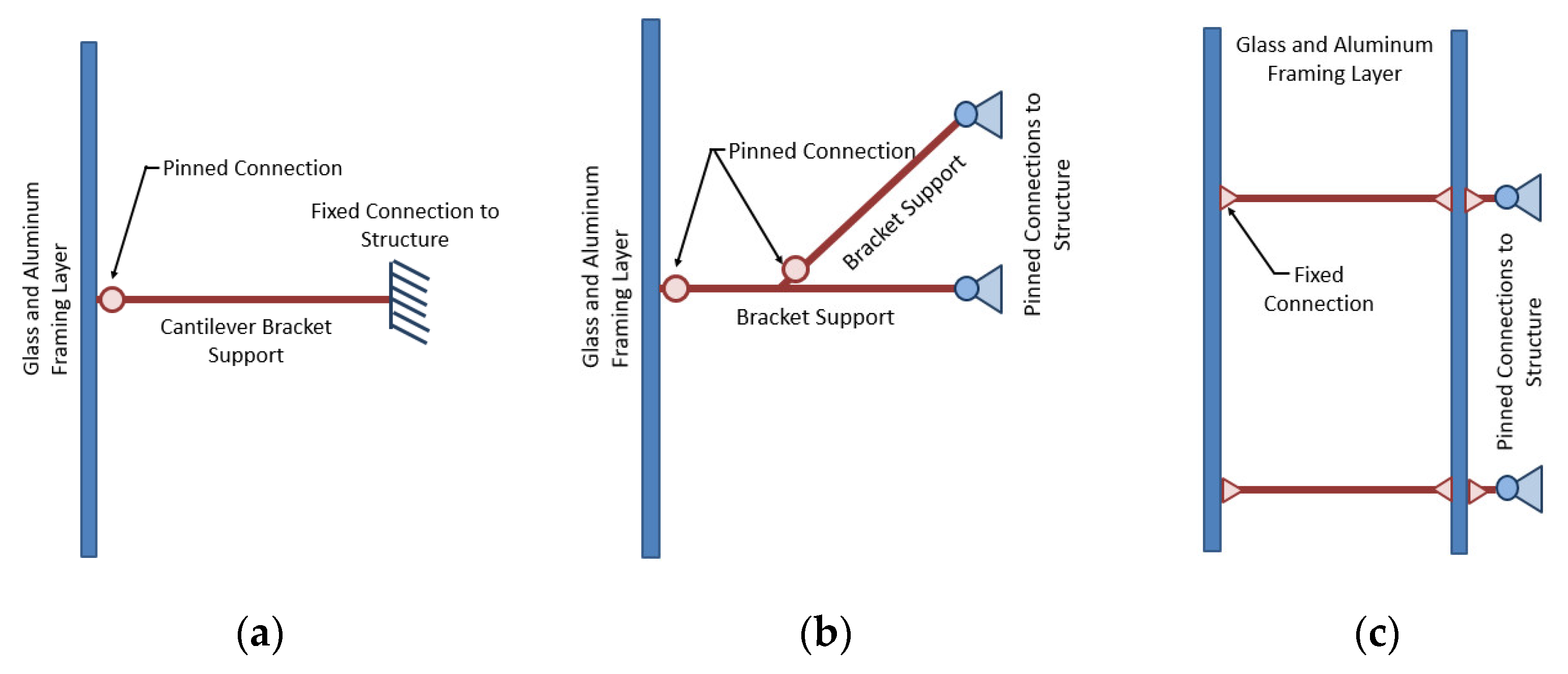
6.2. DSF Support Structure Typologies
6.3. Designer Takeaways on Construction and Structural
7. DSF Research Threads
8. DSF Modeling
8.1. Thermal, Ventilation, and Energy Modeling
- Empirical correlations and simple analytical models;
- Combined thermal and airflow networks models;
- Intermediate explicit models;
- Computational fluid dynamics (CFD) models.
8.1.1. Energy and Ventilation Modeling Methodologies
8.1.2. Hygrothermal Modeling of DSF Systems
8.1.3. DSF Energy Modeling Software Platforms for Industry
8.1.4. Modeling Considerations and Parameters
8.2. Structural Modeling of DSF
8.2.1. Software Packages Capable of DSF Modeling
8.2.2. Idealization of Supports
8.2.3. Loading Conditions
8.2.4. Capturing Failure Mechanisms
8.3. LCA Modeling for DSF Designs
Software Packages to Calculate DSF LCA
8.4. Designer and Modeler Takeaways on Computational Simulations of DSFs
9. Case Studies
10. Conclusions
Author Contributions
Funding
Data Availability Statement
Conflicts of Interest
References
- Arons, D. Properties and Applications of Double-Skin Building Facades. Master’s Thesis, Department of Architecture, Massachusetts Institute of Technology, Cambridge, MA, USA, 2000. [Google Scholar]
- Bestfacade. WP 5 Report Best Practice Guidelines. Best Practice for Double Skin Facades; Intelligent Energy Europe: Brussels, Belgium, 2007. [Google Scholar]
- Crespo, A.M. History of the Double Skin Façades. n.d. Available online: http://envelopes.cdi.harvard.edu/envelopes/content/resources/PDF/doubleskins.pdf (accessed on 15 February 2019).
- Boake, T.; Harrison, K.; Chatham, A. The Tectonics of the Double Skin: Green Building or Just More Hi-Tech Hi-Jinx? University of Waterloo: Waterloo, ON, Canada, 2001. [Google Scholar]
- Straube, J. A Critical Review of the Use of Double Façades for Office Buildings in Cool Humid Climates. J. Build. Enclos. Des. 2007, 48–53. [Google Scholar]
- Penić, M.; Vatin, N.; Murgul, V. Double skin facades in energy efficient design. In Applied Mechanics and Materials; Trans Tech Publications Ltd.: Zurich, Switzerland, 2014; Volume 680, pp. 534–538. [Google Scholar]
- Lang, W.; Herzog, T. Using Multiple Glass Skins to Clad Buildings. Architectural Record. 2000. Available online: http://archrecord.construction.com/features/green/archives/0007edit-1.asp (accessed on 20 June 2015).
- Uuttu, S. Study of Currnet Structures in Double-skin Facades. Master’s Thesis, Department of Civil and Environmental Engineering, Helsinki University of Technology, Helsinki, Finland, 2001. [Google Scholar]
- Saelen, D. Energy Performance Assessments of Single Storey Multiple-Skin Facades. Ph.D. Thesis, Laboratory for Building Physics, Department of Civil Engineering, Catholic University of Leuven, Brussels, Belgium, 2002. [Google Scholar]
- Selkowitz, S. Energy efficiency perspectives: Intelligent networks and the challenge of zero energy buildings. In Proceedings of the Presentation to Connected Urban Development Global Conf., Amsterdam, The Netherlands, 10 April 2008. [Google Scholar]
- Saelens, D.; Roels, S.; Hens, H. Strategies to improve the energy performance of multiple-skin facades. Build. Environ. 2008, 43, 638–650. [Google Scholar] [CrossRef]
- Pollard, B.; Beatty, M. Double skin façades more is less? In Proceedings of the ISES-AP—3rd International Solar Energy Society Conference—Asia Pacific Region, Sydney, Australia, 25–28 November 2008. [Google Scholar]
- Danesh, M.; Escamilla, E.; Pariafsai, F.; Ostadalimakhmalbaf, M. Characteristics of Glazing Layers of Double-Skin Facades and Energy Consumption: A Case Study in Arid Climate of Tehran. In AEI 2019: Integrated Building Solutions—The National Agenda; American Society of Civil Engineers: Reston, VA, USA, 2019; pp. 204–215. [Google Scholar]
- Gratia, E.; De Herde, A. Guidelines for improving natural daytime ventilation in an office building with a double-skin facade. Sol. Energy 2007, 81, 435–448. [Google Scholar] [CrossRef]
- Moon, K.S. Structural Design of Double Skin Facades as Damping Devices for Tall Buildings. In Proceedings of the Twelfth East Asia-Pacific Conference on Structural Engineering and Construction, Hong Kong, China, 26–28 January 2011; pp. 1351–1358. [Google Scholar]
- Siebert, B. Double Skin Facades Made of Glass—Aspects of Structural Design and Static Analysis. In Structures and Archetecture: Concepts, Applications and Challenges; Cruz, P.J.S., Ed.; Taylor & Francis Group: London, UK, 2013; pp. 289–298. [Google Scholar]
- Vaglio, J.; Patterson, M.; Hooper, S. Emerging Applications and Trends of Double-skin Facades. In Proceedings of the International Conference on Building Envelope Systems and Technologies, ICBEST, Vancouver, BC, Canada, 27–30 June 2010. [Google Scholar]
- New Barbosa, S.; Ip, K. Perspectives of double skin façades for naturally ventilated buildings: A review. Renew. Sustain. Energy Rev. 2014, 40, 1019–1029. [Google Scholar] [CrossRef]
- New Kalyanova, O. Double-Skin Facade: Modelling and Experimental Investigations of Thermal Performance; Department of Civil Engineering, Aalborg University: Aalborg, Denmark, 2008. [Google Scholar]
- New Høseggen, R.; Wachenfeldt, B.; Hanssen, S. Building simulation as an assisting tool in decision making: Case study: With or without a double-skin façade? Energy Build. 2008, 40, 821–827. [Google Scholar] [CrossRef]
- New Ghaffarianhoseini, A.; Ghaffarianhoseini, A.; Berardi, U.; Tookey, J.; Li, D.H.W.; Kariminia, S. Exploring the advantages and challenges of double-skin façades (DSFs). Renew. Sustain. Energy Rev. 2016, 60, 1052–1065. [Google Scholar] [CrossRef]
- Diprose, P.R.; Robertson, G. Towards A Fourth Skin? Sustainability and Double-Envelope Buildings; Department of Architecture, University of Auchland: Auckland, New Zealand, 1996. [Google Scholar]
- DOE. Buildings Energy Data Book. Energy Efficiency and Renewable Energy Dept. 2011. Available online: http://buildingsdatabook.eren.doe.gov/docs/DataBooks/2010_BEDB.pdf (accessed on 27 December 2016).
- Crawley, D.B.; Hand, J.W.; Kummert, M.; Griffith, B.T. Contrasting the capabilities of building energy performance simulation programs. Build. Environ. 2008, 43, 661–673. [Google Scholar] [CrossRef]
- Berardi, U. A cross-country comparison of the building energy consumptions and their trends. Resour. Conserv. Recycl. 2017, 123, 230–241. [Google Scholar] [CrossRef]
- Charalambides, J.; Wright, J. Effect of early solar energy gain according to building size, building openings, aspect ratio, solar azimuth, and latitude. J. Archit. Eng. 2013, 19, 209–216. [Google Scholar] [CrossRef]
- Oesterle, E.; Oesterle, R.-D.; Lutz, L.M.; Heusler, W. Double Skin Facades—Integrated Planning; Prestel Verlag: Munich, Germany, 2001. [Google Scholar]
- Silvestre, J.D.; de Brito, J.; Pinheiro, M.D. Building’s external walls in life-cycle assessment (LCA) research studies. In Proceedings of the of SB10–Sustainable Building Affordable to All; iiSBE–Portugal: Vilamoura, Portugal, 2010; pp. 629–638. [Google Scholar]
- Saleem, M.; Chhipi-Shrestha, G.; Túlio Barbosa Andrade, M.; Dyck, R.; Ruparathna, R.; Hewage, K.; Sadiq, R. Life cycle thinking–based selection of building facades. J. Archit. Eng. 2018, 24, 4018029. [Google Scholar] [CrossRef]
- Incropera, F.P. Introduction to Heat Transfer; John Wiley and Sons: New York, NY, USA, 2011. [Google Scholar]
- Ihm, P.; Krarti, M.; Nemri, A. Estimation of lighting energy savings from daylighting. Build. Environ. 2009, 44, 509–514. [Google Scholar] [CrossRef]
- Shehabi, A.; DeForest, N.; McNeil, A.; Masanet, E.; Greenblatt, J.; Lee, E.S.; Masson, G.; Helms, B.A.; Milliron, D.J. U.S. energy savings potential from dynamic daylighting control glazings. Environ. Energy Build. 2013, 66, 415–423. [Google Scholar] [CrossRef]
- Johnson, R.; Selkowitz, S.; Sullivan, R. How Fenestration Can Significantly Affect Energy Use in Commercial Buildings. In Proceedings of the 11th Energy Technology Conference, Washington, DC, USA, 19–21 March 1984. [Google Scholar]
- Jafari, A.; Valentin, V. An Investment Allocation Approach for Building Energy Retrofits; ConstructionResearch Congress (CRC): San Juan, Puerto Rico, 2016; p. 107. [Google Scholar] [CrossRef]
- Aksamija, A.; Peters, T. Heat transfer in facade systems and energy use: Comparative study of different exterior wall types. J. Archit. Eng. 2017, 23, C5016002. [Google Scholar] [CrossRef]
- Fuliotto, R.; Cambuli, F.; Mandas, N.; Bacchin, N.; Manara, G.; Chen, Q. Experimental and numerical analysis of heat transfer and airflow on an interactive building facade. Energy Build. 2010, 42, 23–28. [Google Scholar] [CrossRef]
- Taborianski, V.M.; Prado, R.T. Methodology of CO2 emission evaluation in the life cycle of office building façades. Environ. Impact Assess. Rev. 2012, 33, 41–47. [Google Scholar] [CrossRef]
- Moghtadernejad, S.; Mirza, M.S.; Chouinard, L.E. Facade design stages: Issues and considerations. J. Archit. Eng. 2019, 25, 4018033. [Google Scholar] [CrossRef]
- Pickering, C.; Byrne, J. The benefits of publishing systematic quantitative literature reviews for PhD candidates and other early-career researchers. High. Educ. Res. Dev. 2014, 33, 534–548. [Google Scholar] [CrossRef]
- Boell, S.; Cezec-Kecmanovic, D. Are systematic reviews better, less biased and of higher quality? In Proceedings of the ECIS 2011 Proceedings, Helsinki, Finland, 9–11 June 2011; p. 223. [Google Scholar]
- Gelesz, A.; Reith, A. Classification and re-evaluation of double-skin facades. Int. Rev. Appl. Sci. Eng. 2011, 2, 129–136. [Google Scholar] [CrossRef]
- Doebber, I.; McClintock, M. Analysis process for designing double skin facades and associated case study. In Proceedings of the Second National IBPSA-USA Conference, San Francisco, CA, USA, 2–4 August 2006; pp. 160–167. [Google Scholar]
- Knaack, U.; Klein, T.; Bilow, M.; Auer, T. Façades: Principles of Construction; Birkhäuser: Boston, MA, USA, 2014. [Google Scholar]
- Compagno, A. Intelligent Glass Facades; Birkhauser: Boston, MA, USA, 1999. [Google Scholar]
- Loncour, X.; Deneyer, A.; Blasco, M.; Flamant, G.; Wouters, P. Ventilated Double Facade: Classification and Illustration of Facade Concepts; Belgian Building Research Institute: Saint-Gilles, Belgium, 2004. [Google Scholar]
- Patterson, M.; Matusova, J. High-performance facades. Insight 2013, 3, 134–149. [Google Scholar]
- Boake, T.M.; Harrison, K.; Collins, D.; Balbaa, T.; Chatham, A.; Lee, R.; Bohren, A. The Tectonics of the Double Skin: Green Building or Just More Hi-Tech Hi-Jink?—What Are Double Skin Façades and How Do They Work? University of Waterloo: Waterloo, ON, Canada, 2008; Available online: http://www.architecture.uwaterloo.ca/faculty_projects/terri/ds/tectonic.pdf (accessed on 4 July 2013).
- Kallioniemi, J. Joint and Fastenings in Steel-Glass Facades. Master’s Thesis, Department of Civil and Environmental Engineering, Helsinki University of Technology, Helsinki, Finland, 1999. [Google Scholar]
- Ariosto, T.; Memari, A.M.; Solnosky, R. A Comparative Energy Efficiency Study Of Different Glazing Systems In Residential And Commercial Building Applications. Int. J. Archit. Eng. Constr. 2019, 8, 1–18. [Google Scholar] [CrossRef]
- Schittich, C. Glass Construction Manual; Birkhauser Architecture: Boston, MA, USA, 2007. [Google Scholar]
- Oldfield, P.; Trabucco, D.; Wood, A. Five Generations of Tall Buildings: An Historical Analysis of Energy Consumption in High Rise Buildings. J. Archit. 2009, 14, 591–613. [Google Scholar] [CrossRef]
- Minor, J.E. Focus on Glass. APT Bull. J. Preserv. Technol. 2001, 32, 47–50. [Google Scholar] [CrossRef]
- Goupil, J.; Kestner, D.M.; Lorenz, E. Sustainability Guidelines for the Structural Engineer; ASCE Press: Reston, VA, USA, 2010. [Google Scholar]
- Jayasinghe, C. Embodied energy of alternative building materials and their impact on life cycle cost parameters. ICSECM 2011, 201, 1–20. [Google Scholar]
- Haynes, R. Embodied Energy Calculations within Life Cycle Analysis of Residential Buildings. 2010. Available online: http://etool.net.au/wp-content/uploads/2012/10/Embodied-Energy-Paper-Richard-Haynes.pdf (accessed on 25 July 2018).
- Ghoshal, S.; Neogi, S. Advance Glazing System—Energy Efficiency Approach for Buildings a Review. Energy Procedia 2014, 54, 352–358. [Google Scholar] [CrossRef]
- Ariosto, T.; Memari, A.; Solnosky, R. A comparative thermal properties evaluation for residential window retrofit solutions for U.S. markets. Adv. Build. Energy Res. 2018, 15, 87–116. [Google Scholar] [CrossRef]
- Binions, R.; Ridley, I.; Warwick, M.E.A. The effect of transition gradient in thermochromic glazing systems. Energy Build. 2014, 77, 80–90. [Google Scholar]
- Issa, R.R.A.; Olbina, S.; Raheem, A.A. Environmental Performance and Economic Analysis of Different Glazing–Sunshade Systems Using Simulation Tools. J. Comput. Civ. Eng. 2016, 30, C5016001. [Google Scholar] [CrossRef]
- Hernández, J.A.; Sierra, P. Solar heat gain coefficient of water flow glazings. Energy Build. 2017, 139, 133–145. [Google Scholar]
- IEA (International Energy Agency). Technology Roadmap Energy Efficient Building Envelopes. 2013. Available online: http://www.iea.org/publications/freepublications/publication/TechnologyRoadmapEnergyEfficientBuildingEnvelopes.pdf (accessed on 25 December 2013).
- Papaefthimiou, S. Chromogenic technologies: Towards the realization of smart electrochromic glazing for energy-saving applications in buildings. Adv. Build. Energy Res. 2010, 4, 77–126. [Google Scholar] [CrossRef]
- Piccolo, A.; Marino, C.; Nucara, C.; Pietrafesa, M. Energy performance of an electrochromic switchable glazing: Experimental and computational assessments. Energy Build. 2018, 165, 390–398. [Google Scholar] [CrossRef]
- Granqvist, C.G. Electrochromic tungsten oxide films: Review of progress 1993–1998. Sol. Energy Mater. Sol. Cells 2000, 60, 201–262. [Google Scholar] [CrossRef]
- Lee, E.S.; Gehbauer, C.; Coffey, B.E.; McNeil, A.; Stadler, M.; Marnay, C. Integrated control of dynamic facades and distributed energy resources for energy cost minimization in commercial buildings. Sol. Energy 2015, 122, 1384–1397. [Google Scholar] [CrossRef]
- Pierucci, A.; Cannavale, A.; Martellotta, F.; Fiorito, F. Smart windows for carbon neutral buildings: A life cycle approach. Energy Build. 2018, 165, 160–171. [Google Scholar] [CrossRef]
- Zhang, W.; Lu, L.; Peng, J.; Song, A. Comparison of the overall energy performance of semi-transparent photovoltaic windows and common energy-efficient windows in Hong Kong. Energy Build. 2016, 128, 511–518. [Google Scholar] [CrossRef]
- Cuce, E.; Cuce, P.M.; Wood, C.J.; Riffat, S.B. Toward aerogel based thermal superinsulation in buildings: A comprehensive review. Renew. Sustain. Energy Rev. 2014, 34, 273–299. [Google Scholar] [CrossRef]
- Berardi, U. The development of a monolithic aerogel glazed window for an energy retrofitting project. Appl. Energy 2015, 154, 603–615. [Google Scholar] [CrossRef]
- Martinez, R.G.; Goiti, E.; Reichenauer, G.; Zhao, S.; Koebel, M.; Barrio, A. Thermal assessment of ambient pressure dried silica aerogel composite boards at laboratory and field scale. Energy Build. 2016, 128, 111–118. [Google Scholar] [CrossRef]
- Blanc, S.L.; Hakkarainen, P.; Lee, E.S.; Levi, M.S.; McClintock, M.; McConahey, E.; Myser, M.P.; Sbar, N.L.; Selkowitz, S.E. Active load management with advanced window wall systems: Research and industry perspectives. In ACEEE 2002 Summer Study on Energy Efficiency in Buildings: Teaming for Efficiency; American Council for an Energy-Efficient Economy: Washington, DC, USA, 2002. [Google Scholar]
- Weggel, D.C.; Zapata, B.J. Laminated glass curtain walls and laminated glass lites subjected to low-level blast loading. J. Struct. Eng. 2008, 134, 466–477. [Google Scholar] [CrossRef]
- Tenhunen, O.; Lintula, K.; Lehtinen, T.; Lehtovaara, J.; Viljanen, M.; Kesti, J.; Mäkeläinen, P. Double Skin Facades-Structures and Building Physics. In Proceedings of the 9th Nordic Steel Construction Conference, Helsinki, Finland, 18–20 June 2001; pp. 141–148. [Google Scholar]
- Shirazi, A. Development of a Seismic Vulnerability Evaluation Procedure for Architectural Glass Curtain Walls; The Pennsylvania State University: University Park, PA, USA, 2005. [Google Scholar]
- Memari, A.M.; Hartman, K.H.; Kremer, P.A. Racking Test Evaluation of EN-WALL 7250 Unitized Curtain Wall System with 3M™ VHB™ Structural Glazing Tape; Report Submitted to 3M Industrial Adhesives & Tapes Division; Penn State University: St. Paul, MN, USA, 2011; p. 72. [Google Scholar]
- Memari, A.M. (Ed.) Curtain Wall Systems—A Primer, Consisting of 12 Chapters; American Society of Civil Engineers (ASCE): Reston, VA, USA, 2013. [Google Scholar]
- Dow Corning. Silicone Structural Glazing Manual; Form Number 62-0979H-01; Dow Corning Europe: Brussels, Belgium, 2011. [Google Scholar]
- Jain, A. Hurricane Wind-Generated Debris Impact Damage to the Glazing of a High-Rise Building. In Proceedings of the Seventh Congress on Forensic Engineering, Miami, FL, USA, 15–18 November 2015; pp. 361–370. [Google Scholar]
- Adhikary, S.D. Review of Glazing and Glazing Systems under Blast Loading. Pract. Period. Struct. Des. Constr. 2015, 21, 4015009. [Google Scholar] [CrossRef]
- Fu, T.S.; Zhang, R. Integrating double-skin façades and mass dampers for structural safety and energy efficiency. J. Archit. Eng. 2016, 22, 4016014. [Google Scholar] [CrossRef]
- Githerlet, S.; Gay, J.B.; Guglielmo, F. Window and advanced glazing systems life cycle assessment. Energy Build. 2000, 32, 225–234. [Google Scholar] [CrossRef]
- Wiener, M. Unitized Double Skin Façade Assemblies: Achieving the Needs of Future Envelope Systems through Construction and Performance Advances; University of Southern California: Los Angeles, CA, USA, 2012. [Google Scholar]
- Eli, U.S.C.; Center, E.B.; Square, F.; Center, S.J. Double-Skin Facades in the United States. Available online: https://enclos.com/wp-content/uploads/2020/08/Insight01-Chapter03-Emerging_Applications_and_Trends_of_Double-Skin_Facades.pdf (accessed on 8 September 2019).
- Schmid, F.; Cseh, X.; Rohrer, E.; Teich, M. Double-Skin Façades: Boundary Conditions, Challenging Examples and Developments. CE/Papers 2018, 2, 103–112. [Google Scholar] [CrossRef]
- Brown, B. An Introduction to the Design and Application of Double Skin Facades in North American High-Rise Architecture. Ph.D. Thesis, Institute of Technology, Cork Irland, Ireland, 2016. [Google Scholar]
- Eslamirad, N.S.; Sanei, A. Double Skin Facades in Use, a Study of Configuration and Performance of Double Skin Façade, Case Studies Some Office Buildings. In Proceedings of the 2nd International Conference on Research in Science and Technology, Istanbul, Turkey, 14 March 2016. [Google Scholar]
- Poirazis, H. Double Skin Façades for Office Buildings–Literature Review; Report EDB-R—04/3; Department of Construction and Architecture, Lund University of Technology: Lund, Sweden, 2004. [Google Scholar]
- Gratia, E.; De Herde, A. The most efficient position of shading devices in a double-skin facade. Energy Build. 2007, 39, 364–373. [Google Scholar] [CrossRef]
- Stec, W.; Van Paassen, A.; Maziarz, A. Modelling the double skin façade with plants. Energy Build. 2005, 37, 419–427. [Google Scholar] [CrossRef]
- Chan, Y.C.; Protzman, B.; Tzempelikos, A. Solar optical properties of roller shades: Modeling approaches, measured results and impact on energy use and visual comfort. In Proceedings of the 3rd International High Performance Buildings Conference, West Lafayette, IN, USA, 14–17 July 2014; Purdue University: West Lafayette, IN, USA, 2014. [Google Scholar]
- Choi, W.; Joe, J.; Kwak, Y.; Huh, J.O. Operation and control strategies for multi-storey double skin facades during the heating season. Energy Build. 2012, 49, 454–465. [Google Scholar] [CrossRef]
- Manz, H.; Frank, T. Thermal simulation of buildings with double-skin façades. Energy Build. 2005, 37, 1114–1121. [Google Scholar] [CrossRef]
- Ding, W.; Hasemi, Y.L.; Yamada, T. Natural ventilation performance of a double-skin façade with a solar chimney. Energy Build. 2005, 37, 411–418. [Google Scholar] [CrossRef]
- Moghtadernejad, S.; Chouinard, L.E.; Mirza, M.S. Design strategies using multi-criteria decision-making tools to enhance the performance of building façades. J. Build. Eng. 2020, 30, 101274. [Google Scholar] [CrossRef]
- Guardo, A.; Coussirat, M.; Valero, C.; Egusquiza, E.; Alavedra, P. CFD assessment of the performance of lateral ventilation in Double Glazed Façades in Mediterranean climates. Energy Build. 2011, 43, 2359–2547. [Google Scholar] [CrossRef]
- Yellamraju, V. Evaluation and Design of Double-Skin Façades for Office Buildings in Hot Climates. Master’s Thesis, College of Architecture, Texas A&M University, College Station, TX, USA, 2004. [Google Scholar]
- Silva, F.M.; Gomes, M.G. Gap inner pressures in multi-storey double skin facades. Energy Build. 2008, 40, 1553–1559. [Google Scholar] [CrossRef]
- Ock, J.; Issa, R.R.A.; Olbina, S. Climate Responsive Automatic Operation Strategies for Double Skin Façade (DSF) System of High-Rise Buildings. In Computing in Civil and Building Engineering; ASCE: Reston, VA, USA, 2014; pp. 917–924. Available online: https://itc.scix.net/pdfs/w78-2014-paper-114.pdf (accessed on 7 August 2022).
- Cole, R.J.; Kernan, P.C. Life-cycle energy use in office buildings. Build. Environ. 1996, 31, 307–317. [Google Scholar] [CrossRef]
- Lee, E.; Selkowitz, S.; Bazjanac, V.; Inkarojrit, V.; Kohler, C. High-Performance Commercial Building Façades; Lawrence Berkeley National Laboratory: Berkeley, CA, USA, 2002. [Google Scholar]
- Barkkume, A. Innovative Building Skins: Double Glass Wall Ventilated Façade; New Jersey School of Architecture: Newark, NJ, USA, 2007. [Google Scholar]
- Mohotti, D.; Lunmantara, R.; Ngo, T.; Mendis, P. Improving the safety of buildings through an innovative sustainable façade system. In Proceedings of the International Conference on Sustainable Built Environment (ICSBE), Kandy, Sri Lanka, 13–14 December 2010; University of Moratuwa: Kandy, Sri Lanka, 2010. [Google Scholar]
- Hens, H.; Saelens, D.; Meulenaer, V.D.; Elsen, P. Multiple-skin facades: High tech blessing or not? In Proceedings of the 8th Symposium on Building Physics in the Nordic Countries, Copenhagen, Denmark, 16–18 June 2008; pp. 1–8. [Google Scholar]
- Colantonio, A.; Quirouette, R. Verification of dynamic buffer zone (DBZ) wall assembly performance using infrared thermography. In Thermosense XXIV; International Society for Optics and Photonics: San Diego, CA, USA, 2002; Volume 4710, pp. 288–298. [Google Scholar]
- Chow, W.; Hung, W.; Gao, Y.; Zou, G.; Dong, H. Experimental study on smoke movement leading to glass damages in double-skinned façade. Constr. Build. Mater. 2007, 21, 556–566. [Google Scholar] [CrossRef]
- Moghtadernejad, S.; Mirza, S. Service life safety and reliability of building facades. In Vulnerability, Uncertainty, and Risk: Quantification, Mitigation, and Management; ASCE: Reston, VA, USA, 2014; pp. 116–124. [Google Scholar]
- Popovic, P.L.; Arnold, R.C. Preventing failures of precast concrete facade panels and their connections. In Proceedings of the 2nd Forensic Engineering Congress, San Juan, Puerto Rico, 21–23 May 2000; ASCE: Reston, VA, USA, 2000; pp. 532–539. [Google Scholar]
- Hay, R.; Ostertag, C.P. Innovative Double Skin Façade (DSF) with High Performance Green Hybrid Fiber-Reinforced Concrete (HP-G-HyFRC) for Resilient and Sustainable Buildings. In Proceedings of the AEI 2015, Milwaukee, WI, USA, 24–27 March 2015; pp. 120–133. [Google Scholar]
- Ding, C.; Ngo, T.; Mendis, P.; Lumantarna, R.; Zobec, M. Dynamic response of double skin façades under blast loads. Eng. Struct. 2016, 123, 155–165. [Google Scholar] [CrossRef]
- Kim, D.; Park, C. Difficulties and limitations in performance simulation of a double skin façade with EnergyPlus. Energy Build. 2011, 43, 3635–3645. [Google Scholar] [CrossRef]
- Hensen, J.; Bartak, M.; Drkal, F. Modelin and simulation of a double skin facade system. ASHRAE Trans. 2002, 108, 1251–1259. [Google Scholar]
- Pasut, W.; De Carli, M. Evaluation of various CFD modelling strategies in predicting airflow and temperature in a naturally ventilated double skin façade. Appl. Therm. Eng. 2012, 37, 267–274. [Google Scholar] [CrossRef]
- Safer, N.; Woloszyn, M.; Roux, J.J. Three-dimensional simulation with a CFD tool of the airflow phenomena in single floor double-skin facade equipped with a venetian blind. Sol. Energy 2005, 79, 193–203. [Google Scholar] [CrossRef]
- Chow, C.L. Numerical studies on smoke spread in the cavity of a double-skin facade. J. Civ. Eng. Manag. 2011, 17, 371–392. [Google Scholar] [CrossRef]
- Pappas, A.; Zhai, Z. Numerical investigation on thermal performance and correlations of double skin façade with buoyancy-driven airflow. Energy Build. 2008, 40, 466–475. [Google Scholar] [CrossRef]
- De Gracia, A.; Castell, A.; Navarro, L.; Oró, E.; Cabeza, L.F. Numerical modelling of ventilated facades: A review. Renew. Sustain. Energy Rev. 2013, 22, 539–549. [Google Scholar] [CrossRef]
- Balocco, C. A non-dimensional analysis of a ventilated double façade energy performance. Energy Build. 2004, 36, 35–40. [Google Scholar] [CrossRef]
- Balocco, C.; Colombari, M. Thermal behavior of interactive mechanically ventilated double glazed façade: Non-dimensional analysis. Energy Build. 2006, 38, 1–7. [Google Scholar] [CrossRef]
- Saelens, D.; Roels, S.; Hens, H. The inlet temperature as a boundary condition for multiple-skin facade modelling. Energy Build. 2004, 36, 825–835. [Google Scholar] [CrossRef]
- Jiru, T.E.; Haghighat, F. Modeling ventilated double skin façade—A zonal approach. Energy Build. 2008, 40, 1567–1576. [Google Scholar] [CrossRef]
- Xaman, J.; Alvarez, G.; Lira, L.; Estrada, C. Numerical study of heat transfer by laminar and turbulent natural convection in tall cavities of facade elements. Energy Build. 2005, 37, 787–794. [Google Scholar] [CrossRef]
- Zöllner, A.; Winter, E.R.F.; Viskanta, R. Experimental studies of combined heat transfer in turbulent mixed convection fluid flows in double-skin-facades. Int. J. Heat Mass Transf. 2002, 45, 4401–4408. [Google Scholar] [CrossRef]
- Irfan, M.; Abas, N.; Saleem, M.S. Thermal performance analysis of net zero energy home for sub zero temperature areas. Case Stud. Therm. Eng. 2018, 12, 789–796. [Google Scholar] [CrossRef]
- Abas, N.; Kalair, A.R.; Khan, N.; Haider, A.; Saleem, Z.; Saleem, M.S. Natural and synthetic refrigerants, global warming: A review. Renew. Sustain. Energy Rev. 2018, 90, 557–569. [Google Scholar] [CrossRef]
- Abas, N.; Khan, N. Carbon conundrum, climate change, CO2 capture and consumptions. J. CO2 Util. 2014, 8, 39–48. [Google Scholar] [CrossRef]
- Abas, N.; Kalair, A.; Khan, N.; Kalair, A.R. Review of GHG emissions in Pakistan compared to SAARC countries. Renew. Sustain. Energy Rev. 2017, 80, 990–1016. [Google Scholar] [CrossRef]
- Stritih, U.; Tyagi, V.V.; Stropnik, R.; Paksoy, H.; Haghighat, F.; Joybari, M.M. Integration of passive PCM technologies for net-zero energy buildings. Sustain. Cities Soc. 2018, 41, 286–295. [Google Scholar] [CrossRef]
- Habash, G.; Chapotchkine, D.; Fisher, P.; Rancourt, A.; Habash, R.; Norris, W. Sustainable design of a nearly zero energy building facilitated by a smart microgrid. J. Renew. Energy 2014, 2014, 1–11. [Google Scholar] [CrossRef]
- Raj, B.P.; Meena, C.S.; Agarwal, N.; Saini, L.; Hussain Khahro, S.; Subramaniam, U.; Ghosh, A. A Review on Numerical Approach to Achieve Building Energy Efficiency for Energy, Economy and Environment (3E) Benefit. Energies 2021, 14, 4487. [Google Scholar] [CrossRef]
- Straube, J.; Burnett, E.F.P. Overview of hygrothermal (HAM) analysis methods. Chapter 5. In Moisture Analysis and Condensation Control in Building Envelopes; Trechsel, H.R., Ed.; ASTM: West Conshohocken, PA, USA, 2001; pp. 81–89. [Google Scholar]
- Delgado, J.M.P.Q.; Ramos, N.M.M.; Barreira, E.; De Freitas, V.P. A critical review of hygrothermal models used in porous building materials. J. Porous Media 2010, 13, 221–234. [Google Scholar] [CrossRef]
- Zirkelbach, D.; Schmidt, T.; Kehrer, M.; Künzel, H.M. Wufi® Pro–Manual; Fraunhofer Institute: Stuttgart, Germany, 2007. [Google Scholar]
- Susorova, M.; Angulo, P.; Bahrami, B. Stephens, A model of vegetated exterior facades for evaluation of wall thermal performance. Build. Environ. 2013, 67, 1–13. [Google Scholar] [CrossRef]
- Bruse, M.; Fleer, H. Simulating surface–plant–air interactions inside urban environments with a three dimensional numerical model. Environ. Model. Softw. 1998, 13, 373–384. [Google Scholar] [CrossRef]
- Grunewald, J. Documentation of the Numerical Simulation Program DIM3.1, Volume 2: User’s Guide; Institute of Building Climatology, Faculty of Architecture, University of Technology Dresden: Dresden, Germany, 2000. [Google Scholar]
- Alsaad, H.; Hartmann, M.; Voelker, C. The effect of a living wall system designated for greywater treatment on the hygrothermal performance of the facade. Energy Build. 2022, 255, 111711. [Google Scholar] [CrossRef]
- Salata, F.; Golasi, I.; Vollaro, A.L.; Vollaro, R.L. How high albedo and traditional buildings’ materials and vegetation affect the quality of urban microclimate. A case study. Energy Build. 2015, 99, 32–49. [Google Scholar] [CrossRef]
- Sontag, L.; Nicolai, A.; Vogelsang, S. Validierung der Solverimplementierung des Hygrothermischen Simulationsprogramms DELPHIN; Technical Report; Technische Universität Dresden: Dresden, Germany, 2013. [Google Scholar]
- Ciampi, M.; Leccese, F.; Tuoni, G. Energy analysis of ventilated and microventilated roofs. Sol. Energy 2022, 79, 183–192. [Google Scholar] [CrossRef]
- Charde, M.; Gupta, R. Effect of energy efficient building elements on summer cooling of buildings. Energy Build. 2013, 67, 616–623. [Google Scholar] [CrossRef]
- Gagliano, A.; Patania, F.; Nocera, F.; Ferlito, A.; Galesi, A. Thermal performance of ventilated roofs during summer period. Energy Build. 2012, 49, 611–618. [Google Scholar] [CrossRef]
- Li, D.; Zheng, Y.; Liu, C.; Qi, H.; Liu, X. Numerical analysis on thermal performance of naturally ventilated roofs with different influencing parameters. Sustain. Cities Soc. 2016, 22, 86–93. [Google Scholar] [CrossRef]
- Wakili, K.G.; Simmler, H.; Frank, T. Experimental and numerical thermal analysis of a balcony board with integrated glass fibre reinforced polymer GFRP elements. Energy Build. 2007, 39, 76–81. [Google Scholar] [CrossRef]
- Cascione, V.; Marra, E.; Zirkelbach, D.; Liuzzi, S.; Stefanizzi, P. Hygrothermal analysis of technical solutions for insulating the opaque building envelope. Energy Procedia 2017, 126, 203–210. [Google Scholar] [CrossRef]
- Leccese, F.; Salvadori, G.; Barlit, M. Ventilated flat roofs: A simplified model to assess their hygrothermal behaviour. J. Build. Eng. 2019, 22, 12–21. [Google Scholar] [CrossRef]
- Tian, Y.; Bai, X.; Qi, B.; Sun, L. Study on heat fluxes of green roofs based on an improved heat and mass transfer model. Energy Build. 2017, 152, 175–184. [Google Scholar] [CrossRef]
- Anđelković, A.S.; Mujan, I.; Dakić, S. Experimental validation of a EnergyPlus model: Application of a multi-storey naturally ventilated double skin facade. Energy Build. 2016, 118, 27–36. [Google Scholar] [CrossRef]
- Catto-Lucchino, E.; Goia, F.; Lobaccaro, G.; Chaudhary, G. Modelling of double skin facades in whole-building energy simulation tools: A review of current practices and possibilities for future developments. In Building Simulation; Tsinghua University Press: Beijing, China, 2019; Volume 12, pp. 3–27. [Google Scholar]
- Clarke, J.A.; Hensen, J.L.M. Integrated building performance simulation: Progress, prospects and requirements. Build. Environ. 2015, 91, 294–306. [Google Scholar] [CrossRef]
- Loutzenhiser, P.G.; Manz, H.; Felsmann, C.; Strachan, P.A.; Maxwell, G.M. An empirical validation of modeling solar gain through a glazing unit with external and internal shading screens. Appl. Therm. Eng. 2007, 27, 528–538. [Google Scholar] [CrossRef]
- Aschaber, J.; Hiller, M.; Weber, R. TRNSYS17: New features of the multizone building model. In Proceedings of the 11th International IBPSA Building Simulation Conference, Glasgow, UK, 27–30 July 2009; pp. 1983–1988. [Google Scholar]
- Hand, J.W. The ESP-r Cookbook: Strategies for Deploying Virtual Representations of the Built Environment; University of Strathclyde: Glasgow, UK, 2011. [Google Scholar]
- US Department of Energy. EnergyPlus Version 8.9.0: Engineering Reference; US Department of Energy: Washington, DC, USA, 2018. [Google Scholar]
- Walton, G.N. AIRNET: A Computer Program for Building Airflow Network Modeling; Technical Report, DE-AI01-36CE2101-3; US Department of Commerce, National Institute of Standards and Technology, National Engineering Laboratory: Gaithersburg, MD, USA, 1989. [Google Scholar]
- Walton, G.N.; Dols, W.S. CONTAMW 2.0 User Manual. NISTIR 7251; US Department of Commerce, National Institute of Standards and Technology: Washington, DC, USA, 2002. [Google Scholar]
- Walton, G.N. Passive Solar Extension of the Building Loads Analysis and System Thermodynamics (BLAST) Program; Technical Report; United States Army Construction Engineering Research Laboratory: Gaithersburg, MD, USA, 1981. [Google Scholar]
- Mitchell, R.; Yazdanian, M.; Zelany, K.; Curcija, C. COMFEN 4.1; Lawrence Berkeley National Laboratory: Berkeley, CA, USA, 2012. [Google Scholar]
- MacroFlo. MacroFlo Calculation Methods. Techniques, 1–25. 2012. Available online: https://www.iesve.com/downloads/help/Thermal/Reference/MacroFloCalculationMethods.pdf (accessed on 7 August 2022).
- Hensen, J.; Djunaedy, E. Building simulation for making the invisible visible-air flow in particular. In Proceedings of the International Conference on Energy Efficient Technologies in Indoor Environment, Delft, The Netherlands, 24–25 February 2005. [Google Scholar]
- Kalamees, T. IDA ICE: The simulation tool for making the whole building energy and HAM analysis. Annex 2004, 41, 12–14. [Google Scholar]
- Hilliaho, K.; Lahdensivu, J.; Vinha, J. Glazed space thermal simulation with IDA-ICE 4.61 software—Suitability analysis with case study. Energy Build. 2015, 89, 132–141. [Google Scholar] [CrossRef]
- Kropf, S.; Zweifel, G. Validation of the Building Simulation Program IDA-ICE According to CEN 13791 “Thermal Performance of Buildings–Calculation of Internal Temperatures of a Room in Summer without Mechanical Cooling–General Criteria and Validation Procedures”; Hochschule Technik + Architektur Luzern: Horw, Switzerland; HLK Engineering: Horw, Switzerland, 2001. [Google Scholar]
- Mazzeo, D.; Matera, N.; Cornaro, C.; Oliveti, G.; Romagnoni, P.; De Santoli, L. EnergyPlus, IDA ICE and TRNSYS predictive simulation accuracy for building thermal behaviour evaluation by using an experimental campaign in solar test boxes with and without a PCM module. Energy Build. 2020, 212, 109812. [Google Scholar] [CrossRef]
- TC; ISO. Thermal Performance of Windows, Doors and Shading Devices—Detailed Calculations; ISO: Berlin, Germany, 2001. [Google Scholar]
- Loutzenhiser, P.G.; Manz, H.; Moosberger, S.; Maxwell, G.M. An empirical validation of window solar gain models and the associated interactions. Int. J. Therm. Sci. 2009, 48, 85–95. [Google Scholar] [CrossRef]
- Karlsson, F.; Rohdin, P.; Persson, M.L. Measured and predicted energy demand of a low energy building: Important aspects when using building energy simulation. Build. Serv. Eng. Res. Technol. 2007, 28, 223–235. [Google Scholar] [CrossRef]
- Bring, A.; Sahlin, P.; Vuolle, M. Models for Building Indoor Climate and Energy Simulation; Report of IEA SHC Task; International Energy Agency for Solar Heating and Cooling Programme: Cedar, MI, USA, 1999; p. 22. [Google Scholar]
- Equa Simulation AB. User Manual, IDA Indoor Climate and Energy, Version 4.5. 2014. Available online: http://www.equaonline.com/iceuser/pdf/ICE45eng.pdf (accessed on 20 August 2021).
- TRNSYS User Manual; Version 16; University of Wisconsin: Madison, WI, USA, 2004.
- El-Sadi, H.; Haghighat, F.; Fallahi, A. CFD analysis of turbulent natural ventilation in double-skin façade: Thermal mass and energy efficiency. J. Energy Eng. 2010, 136, 68–75. [Google Scholar] [CrossRef]
- Walton, G.N.; Dols, W.S. CONTAM User Guide and Program Documentation; US Department of Commerce, Technology Administration, National Institute of Standards and Technology: Gaithersburg, MD, USA, 2013. [Google Scholar]
- Weber, A.; Koschenz, M.; Holst, S.; Hiller, M.; Welfonder, T. TRNFLOW: Integration of COMIS into TRNSYS TYPE 56; University of Wisconsin Madison: Madison, WI, USA, 2002. [Google Scholar]
- Pipitone, G.; Barone, G.; Palmeri, A. Optimal design of double-skin façades as vibration absorbers. Struct. Control. Health Monit. 2018, 25, e2086. [Google Scholar] [CrossRef]
- Fu, T.S. Double skin façades as mass dampers. In Proceedings of the 2013 American Control Conference, Washington, DC, USA, 17–19 June 2013; IEEE: Washington, DC, USA, 2013; pp. 4742–4746. [Google Scholar]
- Azad, A.; Ngo, T.; Samali, B. Control of wind-induced motion of tall buildings using smart façade systems. Electron. J. Struct. Eng. 2015, 14, 33–40. [Google Scholar] [CrossRef]
- Samali, B.; Attard, M.M.; Song, C. (Eds.) From Materials to Structures: Advancement through Innovation; CRC Press: Boca Raton, FL, USA, 2013; pp. 431–435. [Google Scholar]
- Carpenter, L.D. Influences on structural engineering. Struct. Des. Tall Spec. Build. 2005, 14, 419–425. [Google Scholar] [CrossRef]
- Solnosky, R.L. Analytical, Communication, and Information Technology Directions in the Structural Industry. Pract. Period. Struct. Des. Constr. 2016, 21, 4015002. [Google Scholar] [CrossRef]
- Solnosky, R.L. Integrated structural processes on innovative multidisciplinary projects supported by building information modeling. J. Archit. Eng. 2017, 23, 5016004. [Google Scholar] [CrossRef]
- Ding, C.; Ngo, T.; Ghazlan, A.; Lumantarna, R.; Mendis, P. Numerical simulation of structural responses to a far-field explosion. Aust. J. Struct. Eng. 2015, 16, 226–236. [Google Scholar] [CrossRef]
- Ngo, T.; Ding, C.; Lumantarna, R.; Ghazlan, A.; Zobec, M. Structural performance of double-skin façade systems subjected to blast pressures. J. Struct. Eng. 2015, 141, 4015064. [Google Scholar] [CrossRef]
- Hu, G.; Hassanli, S.; Kwok, K.C.; Tse, K.T. Wind-induced responses of a tall building with a double-skin façade system. J. Wind. Eng. Ind. Aerodyn. 2017, 168, 91–100. [Google Scholar] [CrossRef]
- Finnveden, G.; Hauschild, M.Z.; Ekvall, T.; Guinée, J.; Heijungs, R.; Hellweg, S.; Koehler, A.; Pennington, D.S. Suh Recent developments in life cycle assessment. J. Environ. Manag. 2009, 91, 1–21. [Google Scholar] [CrossRef] [PubMed]
- Pomponi, F.; D’Amico, B.; Moncaster, A.M. A method to facilitate uncertainty analysis in LCAs of buildings. Energies 2017, 10, 524. [Google Scholar] [CrossRef]
- Ortiz, O.; Castells, F.; Sonnemann, G. Sustainability in the construction industry: A review of recent developments based on LCA. Constr. Build. Mater. 2009, 23, 28–39. [Google Scholar] [CrossRef]
- Jones, C.; Hammond, G. Inventory of Carbon & Energy (ICE) Version 2.0. In Sustainable Energy Research Team (SERT); SERT, Ed.; University of Bath: Bath, UK, 2011. [Google Scholar]
- SimaPro. SimaPro Database Manual Methods Library. Available online: https://simapro.com/wp-content/uploads/2022/07/DatabaseManualMethods.pdf (accessed on 12 September 2022).
- GreenConcrete LCA. GreenConcrete LCA Web Tool. Available online: http://greenconcrete.berkeley.edu (accessed on 1 September 2022).
- Sphera. GaBi Sphera US LCI Database. Available online: https://gabi.sphera.com/america/databases/us-lci-database/ (accessed on 4 September 2022).
- Pratiwi, A.; Ravier, G.; Genter, A. Life-Cycle Climate-Change Impact Assessment of Enhanced Geothermal System Plants in the Upper Rhine Valley. Geothermics 2018, 75, 26–39. [Google Scholar] [CrossRef]
- Athena Institute. Athena Impact Estimator for Buildings V5. Available online: https://calculatelca.com/software/impact-estimator/ (accessed on 4 September 2022).
- Bryan, H. Le Corbusier and the ‘Mur Neutralisant: An Early Experiment in Double Envelope Construction. In Proceedings of the Ninth International PLEA Conference, Seville, Spain, 24–27 September 1991; pp. 257–262. [Google Scholar]
- Tomlinson, R.; Baker, W.; Leung, L.; Chien, S.; Zhu, Y. Case Study: Pearl River Tower. CTBUH J. 2014, 2, 12–17. [Google Scholar]
- SOM. Pearl River Tower Deep Dive into Sustainable Design. Available online: https://www.som.com/projects/pearl-river-tower/#deep-dive-an-extra-sustainable-design (accessed on 7 August 2022).
- Gonchar, J. Pearl River Tower. Architectural Record. March 2014. Available online: https://www.architecturalrecord.com/articles/7971-pearl-river-tower (accessed on 7 August 2022).
- Architizer. Pearl River Tower. Available online: https://architizer.com/projects/pearl-river-tower/ (accessed on 7 August 2022).


| Core Topic | Keywords |
|---|---|
| Double Skin Façade Modeling |
|
| Double Skin Façade Performance |
|
| Double Skin Façade Types and Configuration |
|
| Double Skin Façade Materials |
|
| Typology | Key Features | Reference |
|---|---|---|
| Building-high double-skin |
| [7,41,44,45] |
| Story-high double-skin |
| [7,27,44,45] |
| Box double-skin façade |
| [7,41,44] |
| Shaft façade |
| [27,41,44] |
| Louvers façade |
| [7,27,45] |
| Alternating façade |
| [7,46] |
| Integrated façade |
| [7,26,46] |
| Attribute | Summary of Features | Possible Locations |
|---|---|---|
| Outdoor air curtain | Air introduced into the cavity comes from the outside and is immediately rejected toward the outside. | Forms an air curtain enveloping the outside façade layer. |
| Indoor air curtain | Air comes from the inside of the room and is returned to the inside of the room or via the ventilation system. | Forms an air curtain enveloping the inside façade layer. |
| Air supply | Ventilation of the façade is created with outdoor air. This air is then brought to the inside of the room or into the ventilation system. | These can be located at:
|
| Air exhaust | Air comes from the inside of the room and is evacuated towards the outside thus making it possible to evacuate the air from the building. | These can be located at:
|
| Buffer zone | An air-tight cavity forms a buffer zone between the inside and the outside, with no ventilation of the cavity being possible. | Any layer:
|
| Ventilation Mode | Mechanically Ventilated Exhaust–Air Systems | Non-Ventilated Buffer Systems | Partly or Fully Naturally Ventilated | |
|---|---|---|---|---|
| Operation Mode | indoor air curtain (air exhaust) | buffer zone | outdoor air curtain air supply air exhaust (buffer zone) | |
| Construction type | ||||
| Cavity Typology Configurations | vertically and horizontally partitioned | exhaust–air façade | buffer façade | box-type window façade |
| horizontally partitioned | corridor façade | |||
| multi-story | multi-story exhaust–air façade | multi-story DSF | ||
| mixed partitioning mode | - | - | shaft-box-type façade | |
| Core DSF Configuration Attribute | Disciplines Involves | Considerations to Review |
|---|---|---|
| Ventilation Typologies |
|
|
| Cavity Typologies |
|
|
| Geometric Typologies |
|
|
| Glazing Class | Glazing Sub-Class | Attributes |
|---|---|---|
| Unitized Fill Materials | Gases | Utilization of gas to suppress both convection and conduction behavior between the unitized lite panes. |
| Aerogel | A silica-based lightweight material that is translucent in makeup with high thermal insulation characteristics incorporated into the system via a granular form. | |
| Compartmentalized Systems | Slat Structure | Reduces conduction within the glazing airspace by dividing it into smaller sections. |
| Multi-wall | Systems composed of a polycarbonate sheet or membrane that incorporates complex cellular structures. | |
| Honeycombed | Utilize a honeycombed layer arrangement placed between glass lites. | |
| Spectrally Selective Systems | Films | A monolithic or IUG system with a spectrally selective film suspended between the two lites or adhered to a lite. |
| Tints | Products that are applied directly to the glazing reduce the level of transparency of glazing as a means of reducing solar heat gain. | |
| Coatings | Products that are applied directly to the glazing to control solar heat gain by limiting those wavelengths of light that are allowed to pass through. | |
| Specialty Glazing | Photochromic | Products that regulate a passive transition from clear to tinted appearance based on the amount and intensity of light striking. |
| Thermochromic | Products that regulate a passive transition from clear to tinted appearance based on surface temperature. | |
| Liquid Crystal Devices | Liquid crystals that when introduced to current change from random orients (opaque) to align crystals (clear view). | |
| Electrochromatic | A coating on the glazing that when varying the amount of current through varies the degree of tint in the window. | |
| Gasochromic | A glass-filled lager that relies on a diluted hydrogen gas to cause the color change when exposed to current. |
| DSF Glazing Attribute Class | Disciplines Involves | Considerations to Review |
|---|---|---|
| Glazing Material |
|
|
| Glazing Layers |
|
|
| Glazing Performance |
|
|
| DSF Domain | Disciplines Impacted | Considerations to Review |
|---|---|---|
| Construction Assembly |
|
|
| Structural Support |
|
|
| Discipline Classification | Research Thrusts | Reference |
|---|---|---|
| Solar effects |
| [88] [26] [89] |
| Ventilation |
| [93] [97] [14] [91,98] [103] |
| Sustainability |
| [94] [10,28] |
| Human Comfort |
| [104] |
| Safety |
| [105] |
| Structural |
| [15,106] [46,107] [108] [109] |
| Software Package | Key Features | Reference |
|---|---|---|
| ENVI-Met |
| [133,134,138] |
| Delphin |
| [133,135] |
| WUFI |
| [131,132,144] |
| HAM-Tools |
| [131] |
| Software Package | Key Features | Reference |
|---|---|---|
| EnergyPlus |
| [111,131,153,154,155,156,157] |
| IES Virtual Environment |
| [151,158,159] |
| ESP-r |
| [90] |
| IDA-ICE |
| [160,161,162,163,164,165,166,167,168] |
| TRANSYS |
| [169,170] |
| CONTAM |
| [156,171,172] |
| Main Class | Information Needed to Build the Model |
|---|---|
| DSF Physical Configuration |
|
| DSF Performance Data |
|
| Mechanical Systems |
|
| Electric Lighting System |
|
| Environmental Data |
|
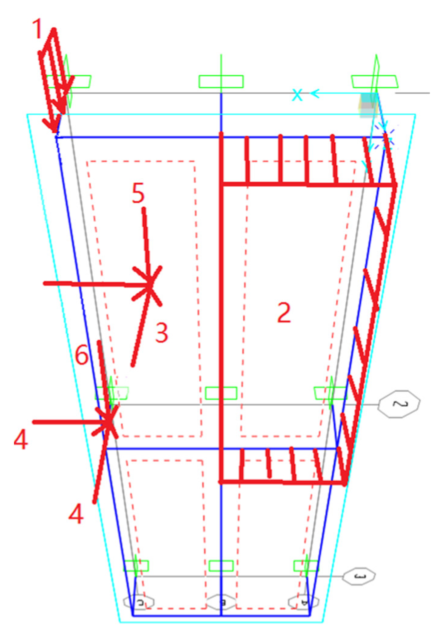
| Load Type | Item | Location in/on the Model | Note |
|---|---|---|---|
| Dead | Exterior glass | Automatically calculated and applied | Program: Modulus of Elasticity Program: Material Density |
| Glass frame and connection—steel | |||
| Catwalk | Location 1 Figure 4 | Depending on how it is modeled—line, point, or area loading | |
| Live | Catwalk for maintenance access | Location 1 Figure 4 | Depending on how it is modeled—line, point, or area loading |
| Wind | C&C wind pressure on exterior skin | Location 2 Figure 4 | ASCE7-16 Chapter 30 |
| Seismic | Seismic demand—horizontal—exterior glass and glass frame | Location 3 Figure 4 | ASCE7-16 Equations 13.3-1, 13.3-2, and 13.3-3 For location 4, it can be horizontal in the plane of the model or out of plane of the model depending on connections. |
| Seismic demand—horizontal—connection and catwalk | Location 4 Figure 4 | ||
| Seismic demand—vertical—connection and catwalk | Location 5 Figure 4 | ASCE7-16 13.3.1: ±0.2DDSWP | |
| Seismic demand—vertical—exterior glass and glass frame | Location 6 Figure 4 |
| Software Package | Key Features | Reference |
|---|---|---|
| SimaPro 8 |
| [29,187] |
| GreenConcrete LCA tool |
| [188] |
| Sphera LCA (GaBi) |
| [89,185] |
| OpenLCA |
| [29,186,187,190] |
| Athena Impact Estimator |
| [29,186,187,191] |
| Modeling Discipline | Core Multi-Disciplinary Considerations | Disciplines to Collaborate with | Simulation Complexity in the Design Stages |
|---|---|---|---|
| Structural |
| Architecture, Mechanical HVAC, Construction | Modeling typically would be performed after the geometry is set for establishing the strategy to support. As the design progresses, the model complexity increases to fully understand behavior. |
| LCA |
| Architecture, Mechanical HVAC, Construction, Structural | Typically performed early in design to ensure the best LCA system is being reached. Often performed at the end of design to confirm LCA has been met. |
| Hygrothermal |
| Architecture, Mechanical HVAC, Energy, Structural | Often performed towards the later stages of design to confirm the performance of the system at a complex level. Could be performed early when generating configurations to ensure there are no major setbacks. |
| Thermal, Ventilation, and Energy |
| Architecture, Mechanical HVAC, Energy, Lighting | This will start out as a more simplistic model early in the design; to verify DSF is a good concept. As the design progresses, the complexity increases to see the impact on other engineered systems. |
| Modeling Discipline | Major Model Categories | Priority Level to Capture | Stage of Design to Consider |
|---|---|---|---|
| Structural | Supports | H M L NA | P SD CD CA |
| Dimensional Coordinates (2D or 3D) | H M L NA | P SD CD CA | |
| Loading | H M L NA | P SD CD CA | |
| Material Behavior | H M L NA | P SD CD CA | |
| Analysis Capturing | H M L NA | P SD CD CA | |
| Design Features | H M L NA | P SD CD CA | |
| LCA | Material Types | H M L NA | P SD CD CA |
| Project Location | H M L NA | P SD CD CA | |
| Database of performance | H M L NA | P SD CD CA | |
| Material Location and Travel | H M L NA | P SD CD CA | |
| Hygrothermal | Dimensional Coordinates (1D, 2D, or 3D) | H M L NA | P SD CD CA |
| Physical Configuration of Materials | H M L NA | P SD CD CA | |
| Material Properties | H M L NA | P SD CD CA | |
| Sophistication of Analysis | H M L NA | P SD CD CA | |
| Thermal, Ventilation, and Energy | DSF Physical Configuration | H M L NA | P SD CD CA |
| DSF Performance Data | H M L NA | P SD CD CA | |
| Mechanical Systems | H M L NA | P SD CD CA | |
| Electric Lighting System | H M L NA | P SD CD CA | |
| Environmental Data | H M L NA | P SD CD CA |
| Foundry Square | One Angel Square | Cambridge Public Library | Pearl River Tower | |
|---|---|---|---|---|
| Location: | San Francisco, CA, USA | Manchester, England | Cambridge, MA, USA | Guangzhou, China |
| Architect: | STUDIOS Architecture | 3DReid | William Rawn Associates | Adrian D. Smith and Gordon Gill |
| Façade engineer | N/A | Waagner Biro, Buro Happold | Ann Beha Architects | Skidmore, Owings & Merrill LLP |
| Façade type: | Multi-story façade | Multi-story façade | Multi-story façade | Multi-story façade |
| Façade supporting structure type | Suspended structure | Cantilever bracket | Frame structure | Frame structure |
| Cavity size: | 0.911 m (3 ft) | 0.610 m (2 ft) | 0.911 m (3 ft) | 0.305 m (1 ft) |
| Shading device type | No shading device | No shading device | 0.305 m (1ft) deep operable sunshades | Daylight reflectors, Motorized blinds/sunshade devices |
| Ventilation devices | Open inlet and outlet | Operable upper and lower vents | Operable upper and lower vents Operable window on inner skin | Low-level inlets with a ducted return air connection |
| DSF Discipline | Major Categories/Considerations | Priority Level to Design towards | Target Level of Performance |
|---|---|---|---|
| Structural | Strength performance | H M L NA | H M Co NA |
| Serviceability performance | H M L NA | H M Co NA | |
| Architecture | Building form and space | H M L NA | H M Co NA |
| Architectural performance | H M L NA | H M Co NA | |
| Materiality | H M L NA | H M Co NA | |
| Functionality | H M L NA | H M Co NA | |
| Integration of systems | H M L NA | H M Co NA | |
| Operations and Maintenance | H M L NA | H M Co NA | |
| Mechanical | Thermal Comfort | H M L NA | H M Co NA |
| Acoustical performance | H M L NA | H M Co NA | |
| Energy performance | H M L NA | H M Co NA | |
| Ventilation performance | H M L NA | H M Co NA | |
| Lighting | Light control | H M L NA | H M Co NA |
| Daylight harvesting vs. electric light | H M L NA | H M Co NA | |
| Visual comfort | H M L NA | H M Co NA |
Publisher’s Note: MDPI stays neutral with regard to jurisdictional claims in published maps and institutional affiliations. |
© 2022 by the authors. Licensee MDPI, Basel, Switzerland. This article is an open access article distributed under the terms and conditions of the Creative Commons Attribution (CC BY) license (https://creativecommons.org/licenses/by/4.0/).
Share and Cite
Memari, A.M.; Solnosky, R.; Hu, C. Multi-Disciplinary Characteristics of Double-Skin Facades for Computational Modeling Perspective and Practical Design Considerations. Buildings 2022, 12, 1576. https://doi.org/10.3390/buildings12101576
Memari AM, Solnosky R, Hu C. Multi-Disciplinary Characteristics of Double-Skin Facades for Computational Modeling Perspective and Practical Design Considerations. Buildings. 2022; 12(10):1576. https://doi.org/10.3390/buildings12101576
Chicago/Turabian StyleMemari, Ali M., Ryan Solnosky, and Chengcong Hu. 2022. "Multi-Disciplinary Characteristics of Double-Skin Facades for Computational Modeling Perspective and Practical Design Considerations" Buildings 12, no. 10: 1576. https://doi.org/10.3390/buildings12101576
APA StyleMemari, A. M., Solnosky, R., & Hu, C. (2022). Multi-Disciplinary Characteristics of Double-Skin Facades for Computational Modeling Perspective and Practical Design Considerations. Buildings, 12(10), 1576. https://doi.org/10.3390/buildings12101576