Article

Cyclic Responses of Two-Side-Connected Precast-Reinforced Concrete Infill Panels with Different Slit Types

1
Key Laboratory of Earthquake Engineering and Engineering Vibration, Institute of Engineering Mechanics, Earthquake Administration, Harbin 150087, China
2
School of Civil Engineering, Suzhou University of Science and Technology, Suzhou 215011, China
*
Author to whom correspondence should be addressed.
Buildings 2022, 12(1), 16; https://doi.org/10.3390/buildings12010016
Submission received: 12 November 2021 / Revised: 16 December 2021 / Accepted: 17 December 2021 / Published: 28 December 2021
(This article belongs to the Special Issue Resilience-Based Structural Seismic Design and Evaluation)

Abstract

:
This study aimed to study the cyclic behavior of two-side-connected precast-reinforced concrete infill panel (RCIP). A total of four RCIP specimens with different slit types and height-to-span ratios modeled at a one-third scale were tested subjected to cyclic lateral loads. The failure mode, hysteretic behavior, lateral strength, stiffness degradation, ductility, and energy dissipation capacity of each RCIP specimen were determined and analyzed. The specimens experienced a similar damage process, which involved concrete cracking, steel rebar yielding, concrete crushing, and plastic hinge formation. All the specimens showed pinched hysteretic curves, resulting in a small energy dissipation capacity and a maximum equivalent viscous damping ratio lower than 0.2. The specimens with penetrated slits experienced ductile failure, in which flexural hinges developed at both slit wall ends. The application of penetrated slits decreased the initial stiffness and lateral load-bearing capacity of the RC panel but increased the deformation capacity, the average ultimate drift ratios ranged from 1.41% to 1.99%, and the lowest average ductility ratio reached 2.48. The specimens with high-strength concrete resulted in a small slip no more than 1 mm between the RC panel and steel beam, and the channel shear connectors ensured that the RC infill panel developed a reliable assembly with the surrounding steel components. However, specimens with concealed vertical slits (CVSs) and concealed hollow slits (CHSs) achieved significantly higher lateral stiffness and lateral strength values. Generally, the specimens exhibited two-stage mechanical features. The concrete in the CVSs and CHSs was crushed, and flexural plastic hinges developed at both ends of the slit walls during the second stage. With increasing concrete strength, the initial lateral stiffness and lateral strength values of the RCIP specimens increased. With an increasing height-to-span ratio, the lateral stiffness and strength of the RC panels with slits decreased, but the failure mode remained unchanged.

1. Introduction

Traditional reinforced concrete (RC) shear walls typically act as the main lateral-resistant seismic components of high-rise buildings in seismic regions because they possess high lateral stiffness and lateral load-bearing capacity. However, RC shear walls generally exhibit moderate deformation capacity. Moreover, they experience severe crushing at their bases, leading to difficulty repairing and retrofitting after an earthquake. A practical solution requiring the combination of steel frames and RC shear walls has been developed. Smith [1] experimentally investigated the mechanical behavior of an infilled steel frame without shear connectors through monotonic loading tests using 42 small-scale specimens. Two failure modes were observed, i.e., diagonal cracking and diagonal crushing. Shear connectors were used at the interface between the steel frame and RC infill wall to enhance the integrity of the composite structure further. The primary function of shear connectors was first demonstrated by Mallick and Severn [2] through a series of half-cyclic dynamic load tests on small-scale infilled steel frames. They found that the adoption of shear connectors in the loaded corner improved the lateral strength. Some experimental studies [3,4,5,6], including cyclic and shake-table tests on infilled steel frames, have verified the crucial role of shear connectors. To prevent beam-to-column connection fracturing failure because of insufficient rotation, some researchers attempted to introduce partially restrained (PR) connections and developed a PR steel frame with RC infill wall (PSRCW) structures [7,8,9,10,11]. The researchers found that preventing the fracturing of the shear connectors was necessary to improve the deformation capacity and ductility of the PSRCW structures. Hou et al. [12] experimentally investigated five steel frame specimens with composite lightweight infill walls under cyclic loads and found that the lightweight concrete infill walls did not enhance the deformation capacity. Dall’Asta et al. [13] developed a new method of designing steel frames with infill walls, in which energy dissipation was expected to occur in vertical steel frame elements. Nonlinear finite element analyses and cyclic tests supported the above design philosophy and showed the advantages of this innovative composite structure. Olsen and Billington [14] developed a seismic retrofitting technique for precast infill panels with ductile high-performance fiber-reinforced concrete and conducted component-level single-panel cyclic tests. Moreover, a two-story single-bay steel frame infilled with high-performance fiber-reinforced concrete infill panels has been analyzed through hybrid simulation [15], and it was found that the retrofitting effectively improved the energy dissipation capacity.
The adoption of slit walls is another useful solution for improving the deformation capacity of a traditional RC wall and preventing fracture failure. Muto [16] used penetrated slits in a solid RC wall, i.e., a slit RC wall; this innovative wall exhibited low lateral stiffness and strength but possessed improved ductility and energy dissipation capacity. Lian and Zou [17] experimentally investigated the hysteretic behavior of six short slit RC walls subjected to cyclic loads and validated the ductile flexural-dominated failure mode of the slit RC walls. Ye et al. [18] adopted an innovative dual-function slit shear wall and performed cyclic tests. They found that the lateral strength increased, owing to the influence of the shear connectors between the slit walls. Zhao et al. [19] modeled a single-span two-story steel frame with prefabricated slit RC infill walls at one-third scale under cyclic loads. Because of the restrained effect of the surrounding steel members, the parallel slit walls experienced flexural-dominated failure at the base and exhibited desirable ductile behavior but showed significantly reduced lateral stiffness. Based on the studies mentioned above, Sun et al. [20,21] developed a novel RC shear wall with unpenetrated concealed vertical slits (CVSs), i.e., a thin concrete wall was placed in the seams between parallel slit walls. This novel reinforced concrete infill wall (RCIW) with CVSs was embedded in the PR steel frame, and a series of cyclic tests were performed. They observed that this novel RCIW with CVSs possessed a two-stage mechanical feature. Before the thinner concrete in the CVSs ruptured, it exhibited shear-dominated deformation at the entire shear panel, which provided large initial lateral stiffness. After the embedded concrete between the slit walls was crushed, the shear panel was divided into separate parallel slit walls and exhibited flexural deformation. Thus, the RC wall with CVSs possessed a large initial stiffness, developed good ductility, and could resist frequent and severe earthquakes. Wang and Wang [22] experimentally investigated the hysteretic behavior of novel concentrated-hollow RC shear walls with a larger aspect ratio. This type of RC shear wall only adopted the large concentrated-hollow part, surrounded by the edge walls at both ends. The test results verified its good deformation capacity and ductility, and it also developed a flexural-shear failure mode due to the large aspect ratio. The abovementioned experimental studies mostly adopted the small-scaled specimens, and the size effect was not considered completely. Because of the complicated interaction between steel frames and infill walls, the effects of the surrounding boundary members were not reflected, and the overall seismic behavior of only RCIWs was not clear. Specially, an RC panel still can be conveniently used as the main lateral load-resisting component for retrofitting ancient concrete or steel frames, and so a simplified connecting method needs to be developed. Therefore, the seismic behavior of two-side-connected precast RCIWs with CVSs, i.e., based on the component-level performance evaluation, still needs to be investigated further.
This paper presents a new slit type—a hollow concealed vertical slit—which is realized by introducing the foam board. The objectives of this study are as follows: (i) to investigate the seismic performance of two-side-connected precast RCIWs with different slits; and (ii) to evaluate the effects of the slit type and height-to-span ratio on its seismic behavior. In the current study, a total of four RCIWs with different slits and height-to-span ratios were designed and subjected to cyclic loads, and the seismic behavior, including the hysteretic curve, lateral strength, stiffness degradation, energy dissipation, and interface slip, were analyzed and compared.

2. Experimental Program

2.1. Specimen Details

Four RC panel specimens with different slits were designed, fabricated, and subjected to horizontal cyclic shear (Table 1), denoted as RCIP-1–4. RCIP-1 and RCIP-4 had a penetrated slit in each RC panel, RCIP-2 had CVSs, and RCIP-3 had concealed hollow slits (CHSs). The height of each specimen was 950 mm. The span of RCIP-1–3 was 1350 mm each, and that of RCIP-4 was 1750 mm. The corresponding height-to-span ratios, i.e., 0.54 and 0.7, were adopted. A pinned T-shaped steel frame was designed and connected with the surrounding loading device to eliminate the effect of the surrounding steel frame. The flange and web of the surrounding T-shaped steel frame were 60 mm × 10 mm (width × thickness) and 110 mm × 10 mm (width × thickness) steel plates, respectively. At the corner of the T-shaped steel frame, the web was removed, and only a 10 mm-thick steel plate was used to reduce the bending capacity significantly. The web of the T-shaped component was drilled with holes of 25.5 mm in diameter to fasten the M24 high-strength bolts. Channel shear connectors were installed using complete penetration groove welds along the internal surface of the T-shaped components at a distance of 100 mm. The section of the channel shear connector was C8 (C80 mm × 43 mm × 5 mm × 8 mm; section height × flange width × web thickness × flange thickness) with a length of 20 mm. The T-shaped steel beams, columns, and channels were made of Q235B steel with a nominal yield strength of 235 N/mm2. The test specimens are depicted in Figure 1.
RCIP-1 and RCIP-4 had penetrated slits, and the width of each slit was 20 mm. Two types of concealed slits were introduced in RCIP-2 and RCIP-3. RCIP-2 had CVSs, where the width of each CVS was 20 mm, and the unpenetrated concrete thickness was 30 mm. RCIP-3 had CHSs, where the thickness of the unpenetrated concrete at the outer parts was 40 mm, and its width was also 20 mm. The foam board was introduced to develop the CHSs in the RC panel. The height of each slit wall was 660 mm, and the panel thickness of each specimen was 80 mm. The slit wall widths of RCIP-1–3 at the central region and both ends were 245 and 135 mm, respectively. The corresponding widths of the slit walls of RCIP-4 were 220 and 145 mm, respectively. Six 6.5 mm in diameter, smooth, mild longitudinal rebars were embedded in the 245 and 220 mm separate slit walls, and the corresponding steel rebar ratios were approximately 1.01% and 1.13%, respectively. The longitudinal rebars at the top and bottom solid wall parts were anchored completely. The confining reinforcement cages were arranged around the RC panel perimeter to prevent the splitting of the shear connectors in the panel thickness direction. Smooth steel-wire two-legged closed stirrups of 4 mm in diameter spaced at 50 mm were placed in the slit walls and surrounding reinforcement cages. Figure 2 shows the dimensions and reinforcement details of the RC panels.

2.2. Material Properties

The average yield strength, tensile stress, elastic modulus, and elongation at fracture of coupons from the steel rebars and channel shear connectors used in the specimens are listed in Table 2. Because the channel flange only provided anchorage and the channel web sustained most of the lateral shear, the channel web was selected to fabricate the coupon specimen. The actual thickness of the channel web was 5.1 mm, which was somewhat larger than the nominal thickness. Steel wires of 4 mm in diameter were fabricated through cold drawing, resulting in a 11.3% elongation during fracturing. Moreover, the average compressive strengths of the 150 mm concrete cubes, fcu, of RCIP-1–2 and RCIP-3–4 were 10.20 and 27.55 MPa, respectively. During the concrete pouring process of the test specimens, some inappropriate measures are adopted by workers. To the first two specimens were added some extra water during the pouring process to maintain a good workability, which led to the low concrete strength. Therefore, the behavior of the RCIP with low-strength concrete was also evaluated.

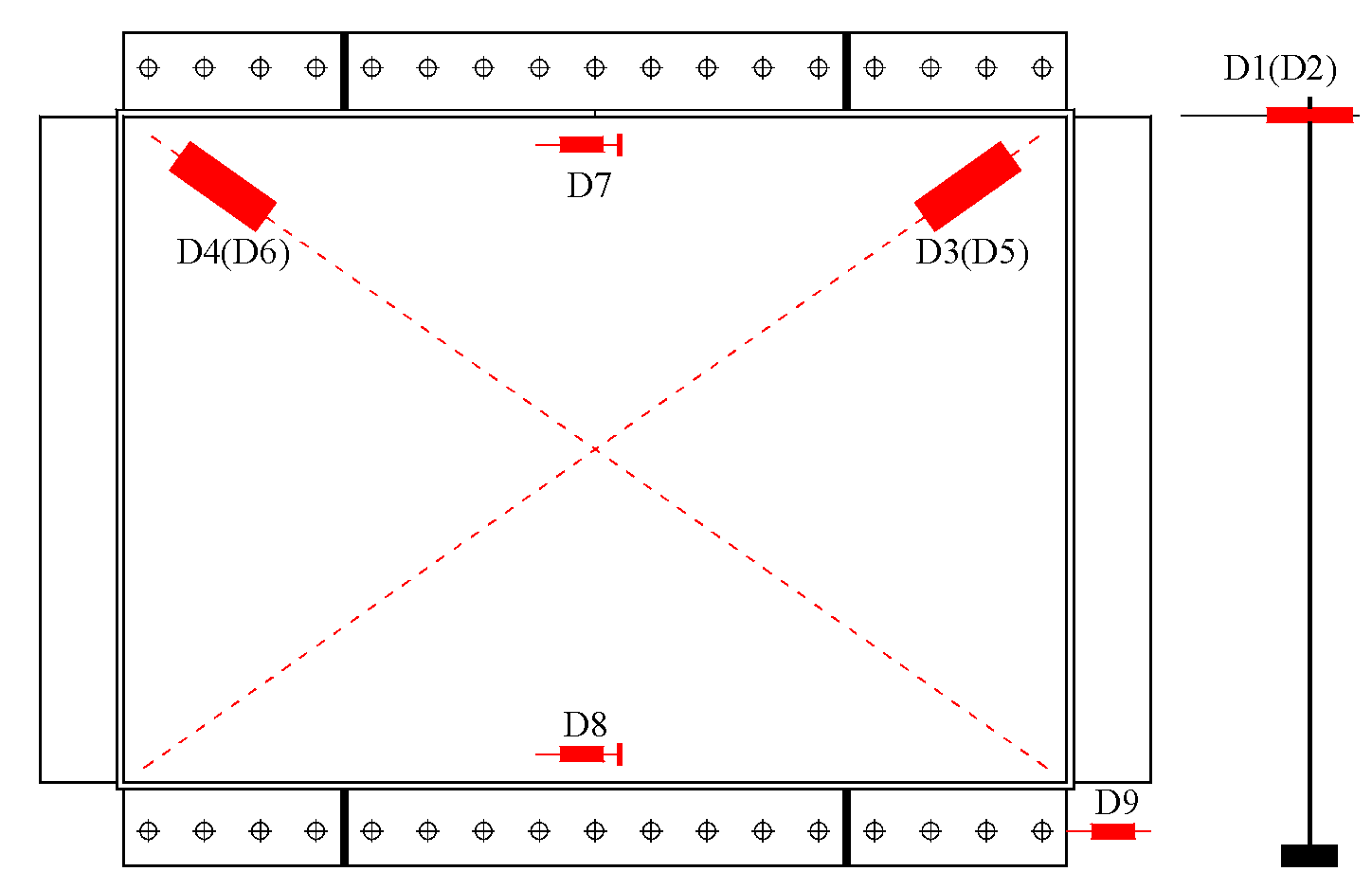
2.3. Test Setup and Instrumentation

The test setup of the lateral loading system is shown in Figure 3. A pinned loading frame was designed and fabricated to induce lateral shear on the RCIP specimens, and each specimen was installed in the pinned loading frame. The main components of the pinned loading frame included two vertical struts, a loading beam, a bottom beam, and vertical struts connected to the loading and bottom beams using four in-plane plate hinges. The specimens were bolted to the loading and bottom beams using 17 high-strength bolts, each being 24 mm in diameter and of 12.9 grade. Lateral loads were applied using a computer-controlled hydraulic testing system. An actuator provided a maximum push–pull force of ±1000 kN and displacement of ±250 mm. The actuator was connected to the reaction frame using four 36 mm in diameter steel rods. A lateral bracing system was adopted to prevent the out-of-plane displacement of the test specimens.
The arrangement of linear variable differential transformers (LVDT) is depicted in Figure 4. D1 and D2 were arranged to monitor the top lateral displacement of the test specimens. D3–D6 LVDTs were placed in the main diagonal directions to record the shear deformation of the RC panels. D7 and D8 were installed to monitor the interface slip between the RC panel and the surrounding steel beam. In addition, the rigid body displacement of the test specimen was monitored using D9.

2.4. Loading Protocol

The loading protocol I adapted to quasi-static cyclic testing (FEMA-461) [23] was employed and controlled at a drift ratio (θ = δ/h) for all the specimens, where δ is the lateral displacement and h is the vertical distance between pins. In the first cycle, the preload of 0.05% was applied to verify the data-acquisition system. Next, each displacement cycle was repeated twice based on the loading protocol (Figure 5). After a drift ratio of 1% was reached, an increment of 0.5% was continuously applied until the specimen failed. Cyclic loading was controlled by technicians at a considerably low speed to avoid dynamic effects.

3. Test Results and Discussion

3.1. Damage and Failure Patterns

The RC panel of RCIP-1 had traditional penetrated slits. The first short inclined crack appeared at the toe of the left slit wall when the drift ratio was 0.4%. Subsequently, more inclined cracks were formed around both ends of the slit walls, and minor inclined cracks appeared on the slit walls; these minor cracks were oriented at approximately ±60° to the horizontal direction. At a drift ratio of 1%, the tiny inclined cracks at the ends of the slit walls widened and gradually extended along the horizontal direction, and the vertical rebars started to yield gradually. The concrete started rupturing, and RCIP-1 achieved a maximum lateral load of 124.8 and −107.2 kN in the positive and negative loading directions, respectively. When the drift ratio reached 2%, the concrete cover began to spall, and concrete crushing became severe (Figure 6a). Next, concrete spalling occurred, the vertical rebars were exposed, and buckling occurred until the test was terminated at a drift ratio of 4% (Figure 6b).
Specimen RCIP-2 had CVSs in its RC panel. Compared to RCIP-1, RCIP-2 showed a typical shear-dominated deformation pattern. The first crack appeared in the CVSs, and the inclined angle was approximately 90° to the horizontal direction. More vertical slits were then formed in the CVSs. The extended inclined cracks in the slit walls oriented at approximately ±45° to the horizontal direction were monitored until the drift ratio reached 0.75%. At a drift ratio of 1%, the concrete in the CVSs started rupturing and spalling. When the drift ratio reached 1.5%, the long-inclined cracks extended gradually, and some CVSs penetrated the specimen (Figure 7a). RCIP-2 reached the maximum lateral load-bearing capacities of 187.5 and −182.7 kN in the positive and negative loading directions, respectively, which were higher than those of RCIP-1. Plastic hinges were formed at both slit wall ends when the drift ratio reached 2%, and the concrete at the slit wall root started to spall. The vertical rebars buckled until the drift ratio reached 4% because of concrete cover spalling (Figure 7b).
RCIP-3 had CHSs in its RC panel, and the hollow part was achieved by placing the foam benzene board. The first crack was monitored at a drift ratio of 0.4%, the crack length was approximately 30 mm, and the inclined angle was approximately 45°, indicating that the shear force mainly induced cracking. Next, long inclined cracks appeared in the middle region of the slit walls. The main difference in the behavior between RCIP-3 and RCIP-1 was that most of the cracks in RCIP-3 were mainly formed in the middle region of the slit walls. At a 0.75% drift ratio, the vertical cracks broadened and extended continuously. When the drift ratio reached 1%, the concrete cover outside the CHSs fell off, and visible penetrating vertical slits were observed. Moreover, parts of the steel rebars yielded. RCIP-3 achieved the maximum lateral load-bearing capacities of 453.9 and −430.3 kN in the positive and negative loading directions, respectively. Subsequently, the surrounding concrete of the CHSs was damaged severely (Figure 8a), and plastic hinges were gradually formed at both ends of the slit walls, similar to RCIP-1. Additionally, the lateral strength of RCIP-3 decreased slowly.
At a drift ratio of 3.5%, the distributed steel rebars were exposed, cover concrete spalling occurred, and the back of the RC panel deformed severely. At a drift ratio of 4%, most of the concrete in the plastic hinge region fell off (Figure 8b). Although the lateral load-bearing capacity of RCIP-3 was high, no visible interface slip was observed during the entire loading process.
RCIP-4 also had penetrated slits in its RC panel but with a smaller height-to-span ratio than RCIP-1. Compared to RCIP-1, more extended inclined cracks appeared in the middle of the slit walls of RCIP-4. Under cyclic loads, these extended inclined cracks developed a cross-grid distribution state. The main reason was the small height-to-span ratio of RCIP-4, which caused the specimen to exhibit shear characteristics. Additionally, the foam benzene boards were not removed during testing, which aggravated the damage on the slit walls. At a drift ratio of 1–1.5%, with crack widening and steel-rebar yielding, RCIP-4 reached the maximum lateral load-bearing capacities of 868.1 and −900.4 kN in the positive and negative loading directions, respectively (Figure 9a). At a 3.5% drift ratio, the slit walls were split into multiple diamond walls. When the drift ratio reached 4%, the concrete in the cross-grid region fell off, and the vertical steel rebars buckled and were exposed (Figure 9b).
Failure mode I: For RCIP-1 and RCIP-4, which had penetrated slits, a few inclined cracks appeared at the ends of the slit walls during the initial loading stage. Several horizontal cracks appeared at both ends of the slit walls during the loading process. The concrete at the corner was crushed in the later loading stage, and plastic hinges developed at both slit wall ends. In this RC panel type, horizontal shear was transferred through the flexural bending of the slit walls. The failure mode is shown in Figure 10a. The most important reason of the occurrence of the preferable flexural failure mode is that the integral RC panel is divided into a series of slit walls with a large aspect ratio, which usually produce the ductile flexural deformation mode.
Failure mode II: For RCIP-2 with CVSs and RCIP-3 with CHSs, before the CVSs and CHSs were crushed during the initial loading stage, the RC panel exhibited a shear-dominated failure pattern and had several extended inclined cracks. Lateral shear was mainly transferred through inclined compression. During the loading process, the concrete in the CVSs and CHSs was crushed, and horizontal cracks developed at both slit wall ends, and the deformation pattern of the RC panel changed from shear to flexure. In the later loading stage, the RC panel also developed flexural plastic hinges at both ends of the slit walls and sustained lateral shear through flexural-dominated deformation of the slit walls. The failure mode is depicted in Figure 10b. The most important reason for developing the two-stage mechanical feature is the adoption of CVSs and CHSs, which can be regarded as a fuse that provides the much larger lateral stiffness and peak load at the initial loading stage. Furthermore, the large aspect ratio of slit walls is achieved at the second loading stage, which provides the much larger deformation capacity and produces the ductile failure mode.

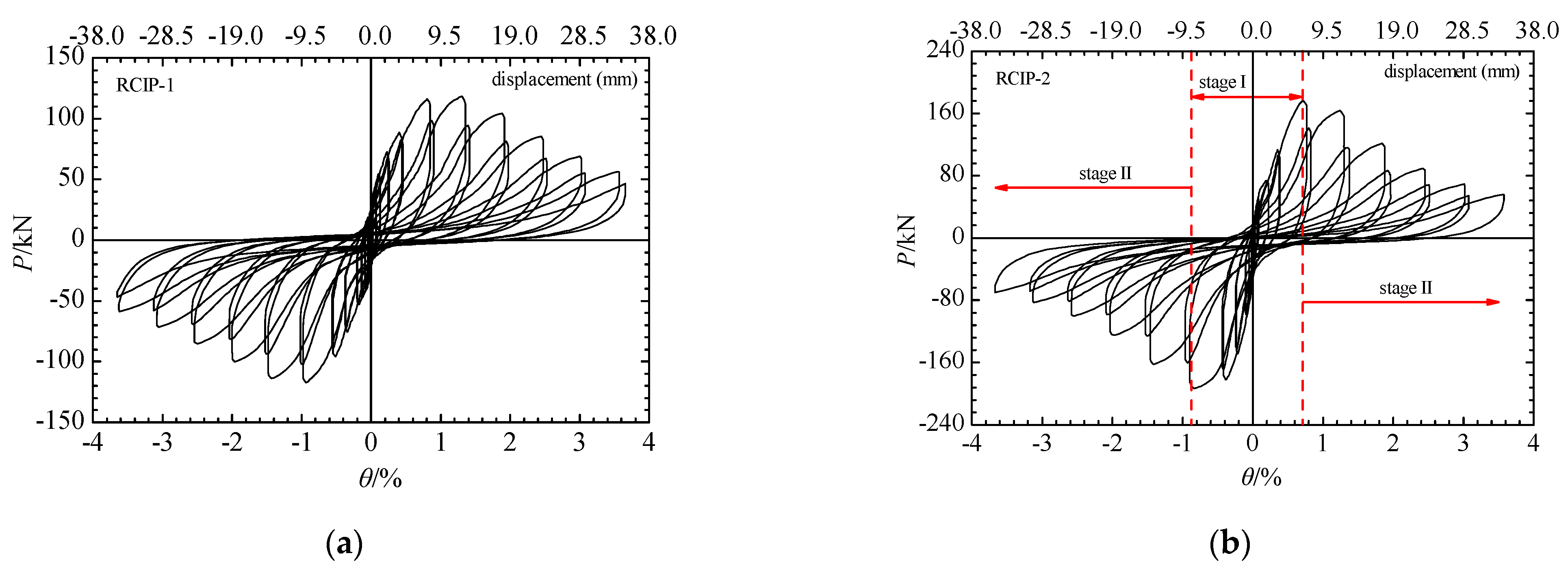
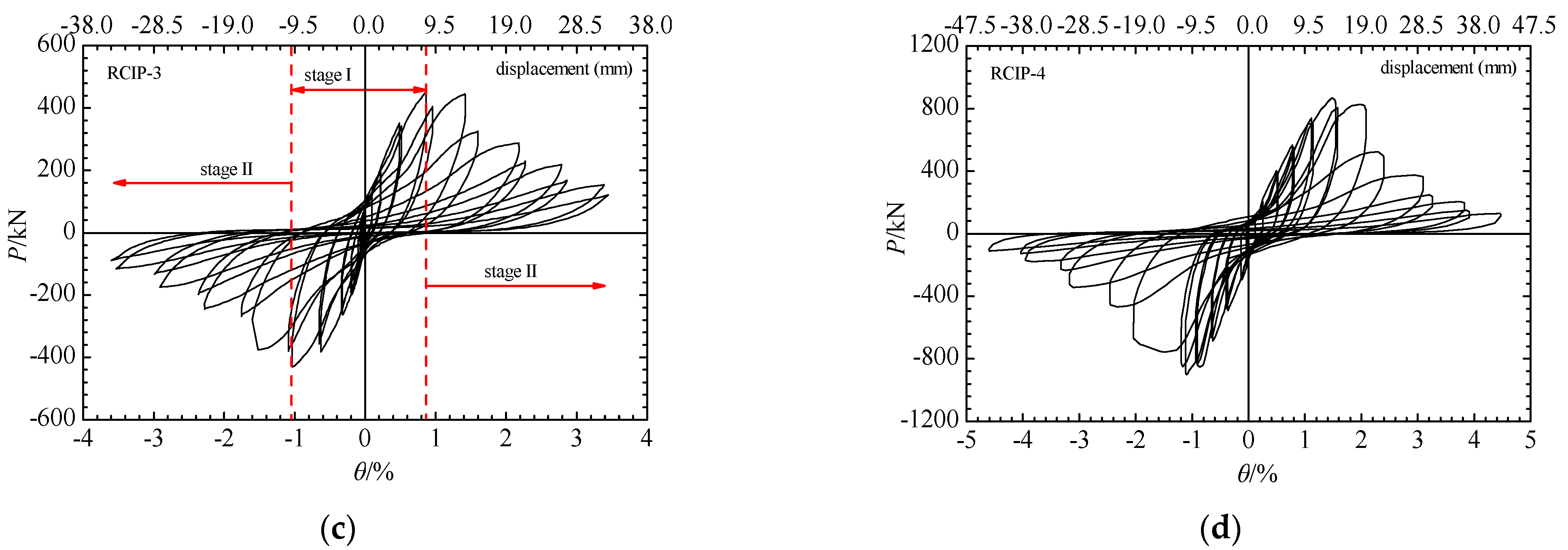
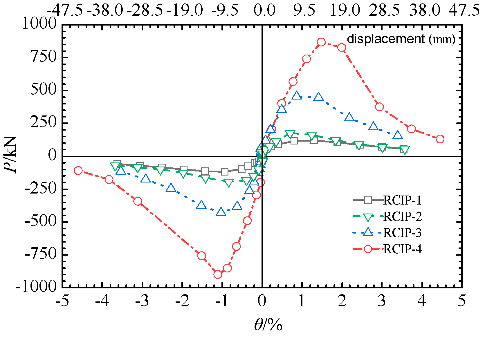
3.2. Lateral Load–Drift Ratio Hysteretic Response

Figure 11 depicts the measured lateral load (P) versus the drift ratio (θ) response. All specimens showed relatively similar pinching hysteretic loops up to failure, indicating limited energy dissipation. Before yielding, all hysteretic loops exhibited a somewhat linear behavior, and the residual drift ratio after unloading could be neglected. Subsequently, the curves had slightly nonlinear positive slopes, owing to the flexural cracks at the slit wall ends of RCIP-1 and RCIP-4, vertical shear cracks in the CVSs of RCIP-2 and CHSs of RCIP-3, and steel rebar yielding and strain hardening. After the peak load was attained, the hysteretic behavior of all specimens began to decline because of crack opening and closing and steel rebar yielding. For the low-strength concrete, RCIP-1 and RCIP-2 showed slightly slower lateral load degradation than RCIP-3 and 4. Although different slits and concrete grades were adopted in the specimens, both parameters did not significantly influence the hysteretic loop shape.

3.3. Lateral Load–Drift Ratio Hysteretic Response

Table 3 lists the characteristic lateral loading responses of the tested specimens. The yield load (Py), yield drift ratio (θy), ultimate load (Pu), and ultimate drift ratio (θu) were determined using the method described in [17], as shown in Figure 12. The curves for the lateral load versus the drift ratio envelope for all specimens are depicted in Figure 13. The presence of CVSs in the RC panel resulted in a higher load-bearing capacity than the RC panels with penetrated slits. Consequently, the average peak lateral strength of RCIP-2 was approximately 1.57 times that of RCIP-1. Nevertheless, the concrete strength significantly influenced the average peak strength of RCIP-2 compared to that of RCIP-3, although RCIP-2 had different concealed slits. When the concrete strength increased by 2.7 times, the corresponding peak lateral strength of RCIP-3 was approximately 2.4 times that of RCIP-2. A possible reason was that the concrete in RCIP-3 had higher compressive stress than that in RCIP-2. Therefore, concrete strength was a critical factor that influenced the lateral strength of the RC panels. Among the specimens with penetrated slits, RCIP-4 exhibited an overall higher lateral load-bearing capacity than RCIP-1. An increase in the RC panel span and concrete strength significantly increased the average peak load of RCIP-4 by approximately 7.5 times, compared to that of RCIP-1. Generally, the height-to-span ratio was another significant parameter that influenced the lateral load-bearing capacity of the RC panel.

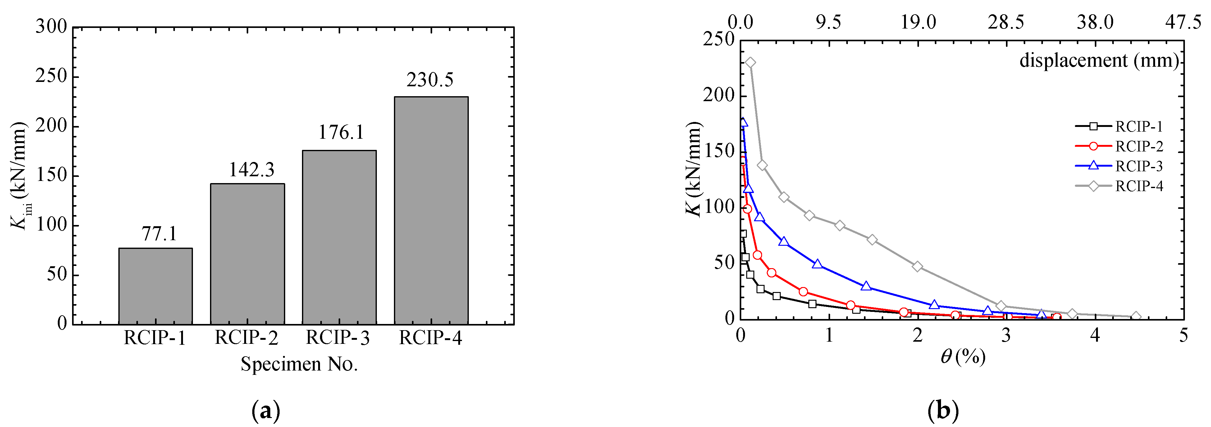
3.4. Initial Lateral Stiffness and Stiffness Degradation

The average lateral secant stiffness, i.e., the peak-to-peak stiffness, was adopted to evaluate the lateral resistance of the structure or component and calculated using Equation (1):
K i = | + P i | + | P i | | + θ i | + | θ i |
where K is the lateral stiffness, +Pi and −Pi are the lateral loads at the ith loading level in the push and pull loading directions, respectively, and +θi and −θi are the drift ratios at the ith loading level in the push and pull loading directions, respectively.
The relationship between the secant stiffness and drift ratio for all specimens are depicted in Figure 14. For the specimens with penetrated slits, the secant stiffness significantly increased from 77.1 kN/mm (RCIP-1) to 230.5 kN/mm (RCIP-4) because of the high-strength concrete and low height-to-span ratio. The initial stiffness values of RCIP-2 and RCIP-3 were 84.5% and 128% higher than that of RCIP-1, indicating that the slit type significantly influenced the initial lateral stiffness of the RC panel. As the height-to-span ratio increased, the initial stiffness of the specimens decreased sharply. However, irrespective of whether the hollow part concrete was inside or outside the RC panel, RCIP-2 and RCIP-3 had a similar initial stiffness, although the unpenetrated concrete panel had slightly different thicknesses. The secant stiffness of each specimen decreased with an increasing drift ratio (Figure 14b), implying that the damage on the RC panel gradually became severe. Under cycles with lateral drift ratios lower than 0.3%, the lateral stiffness decreased rapidly. After the drift ratio exceeded 0.3%, the lateral stiffness gradually degraded as the specimens reached the plastic stage. When the CVSs and CHSs of RCIP-2 and RCIP-3 ruptured, respectively, their corresponding lateral stiffnesses decreased to 25.23 and 49.06 kN/mm, which were still higher than that of RCIP-1. Therefore, the adoption of CVSs or CHSs effectively increased the initial lateral stiffness and decreased the stiffness degradation.

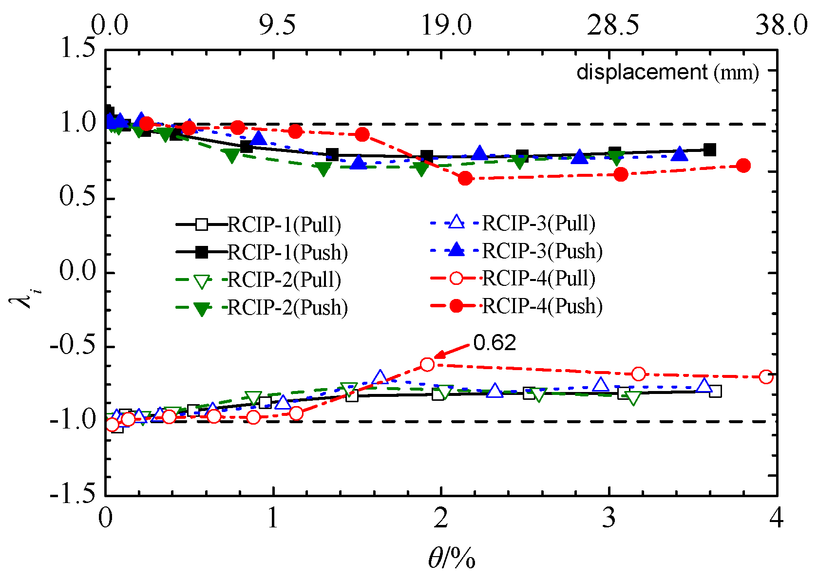
3.5. Lateral Strength Degradation

The strength degradation coefficient, λ, was usually introduced to determine the damage state of the test specimen at the same loading level. It was obtained as follows:
λ i = P i , 2 P i , 1
where λi is the strength degradation coefficient at the ith loading level, and Pi,1 and Pi,2 are the maximum lateral load of the first and second cycles, respectively, at the ith loading level. The relationship between the strength degradation coefficient and drift ratio for all specimens were plotted (Figure 15). All specimens exhibited different damage and strength degradation states at the same loading level. Before the peak load was attained, the RC panel damaged slightly, the degree of strength degradation was low, and the corresponding degradation coefficient was generally higher than 0.9. RCIP-1 and RCIP-4 developed flexural plastic hinges at both slit wall ends after attaining the peak load, and the concrete in the CVSs of RCIP-2 and CHSs of RCIP-3 cracked steadily. With distributed steel-rebar yielding, concrete crushing, and concrete spalling, the strength degradation of all specimens became severe. RCIP-4 experienced the most severe strength degradation, and its strength degradation coefficient decreased to 0.62. The strength degradation rates of the other three specimens were relatively slower, but their strength coefficients decreased to approximately 0.7.

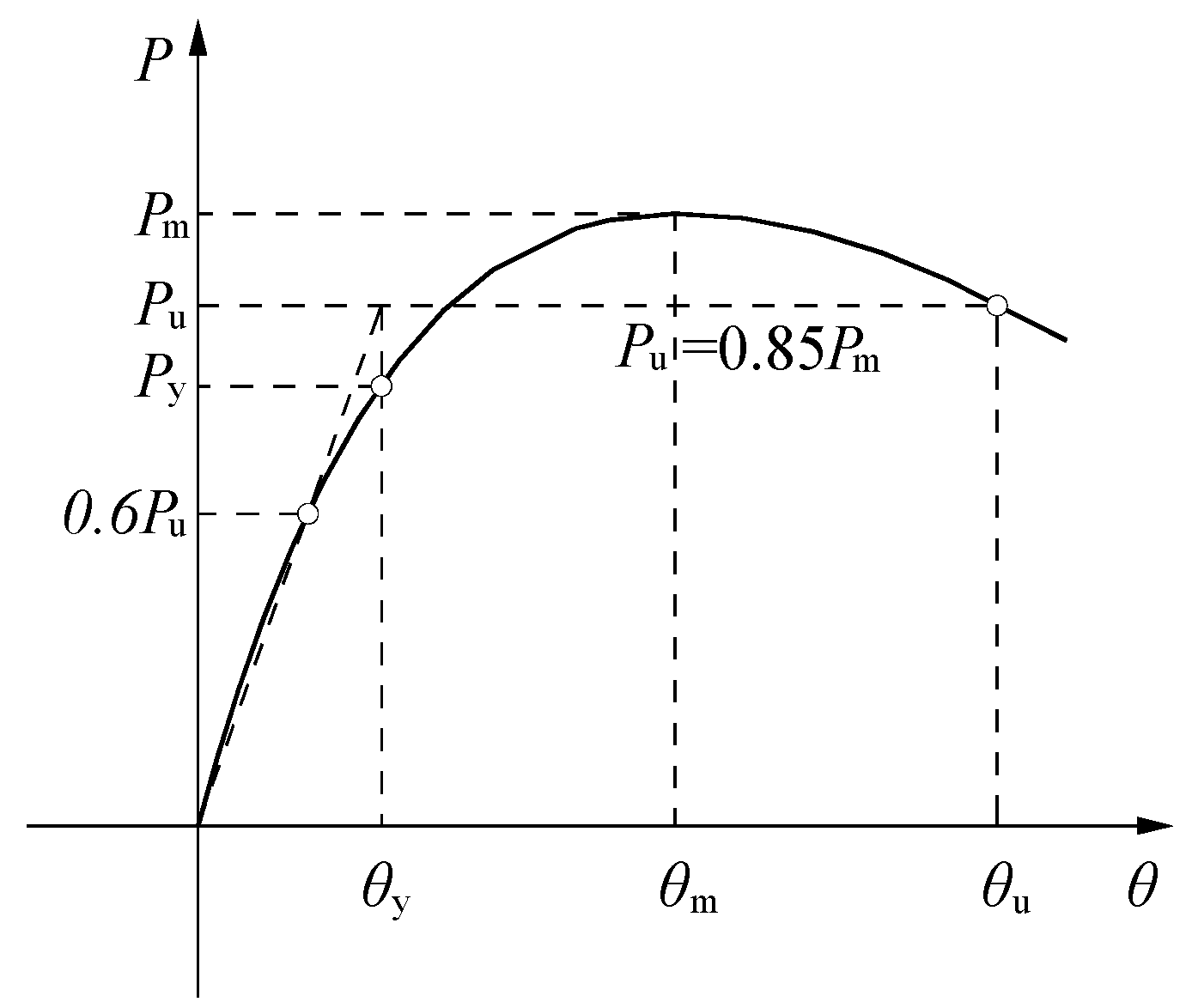
3.6. Deformability and Ductility

The deformation capacity of a structure or component can be evaluated not only by using the ultimate drift ratio but also by using the nondimensional ductility ratio index, which is calculated using Equation (3):
μ = θ u θ y
where μ is the ductility ratio, θu is the ultimate drift ratio, and θy is the yield drift ratio. RCIP-1 and RCIP-4, which had penetrated slits, reached an ultimate drift ratio value exceeding 1.8% each (Table 3), which was higher than those of RCIP-2 and RCIP-3. RCIP-4 had the lowest average ductility ratio of 2.48, although it developed a considerable ultimate drift ratio of 1.84%. As described earlier, the use of CVSs and CHSs enhanced the initial stiffness of the specimens, which resulted in low yield drift ratios; thus, the calculated ductility ratio of RCIP-4 was lower than those of other specimens. In addition, RCIP-1 reached the average peak load at a drift ratio of 1.12%, which was 44% higher than that of RCIP-2, indicating that the presence of concrete in the CVSs significantly increased the lateral stiffness and decreased the ultimate deformability. It was also observed that during the early deformation stage, the RC panel with a low height-to-span ratio deformed as a general shear panel and caused significant damage. At a constant drift ratio, the damage states of the specimens with penetrated slits were less significant than those of specimens with CVSs and CHSs. Therefore, at the next loading level, the specimens with CVSs and CHSs experienced more severe damage than specimens with penetrated slits, which resulted in lower ultimate drift ratios. Additionally, the effect of concrete strength on RC panel deformability was minimal based on the experimental results.

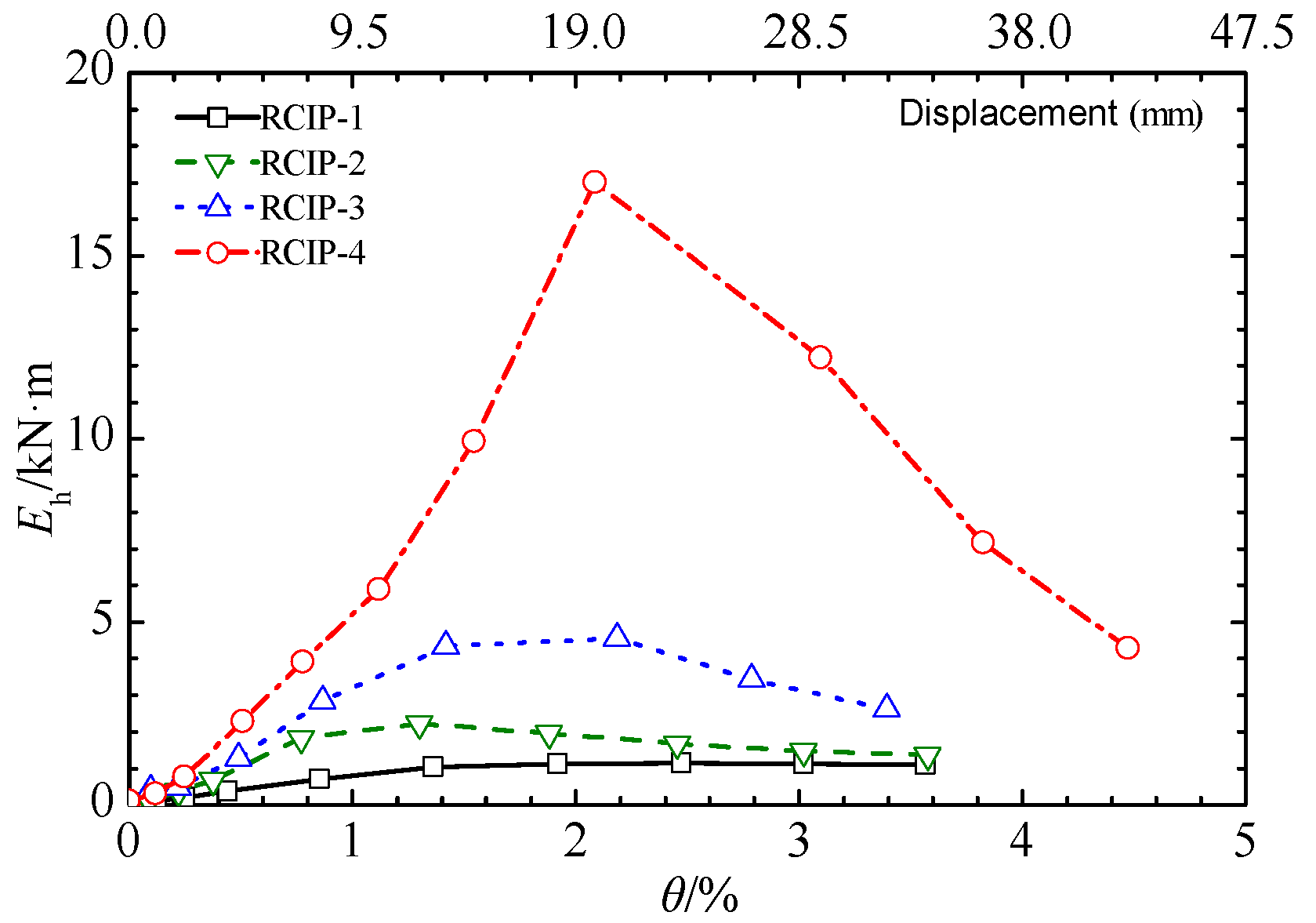
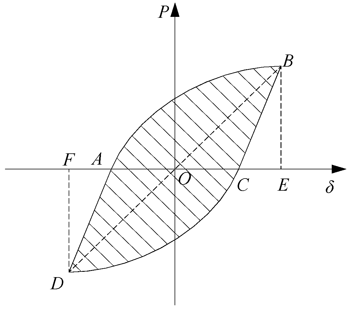
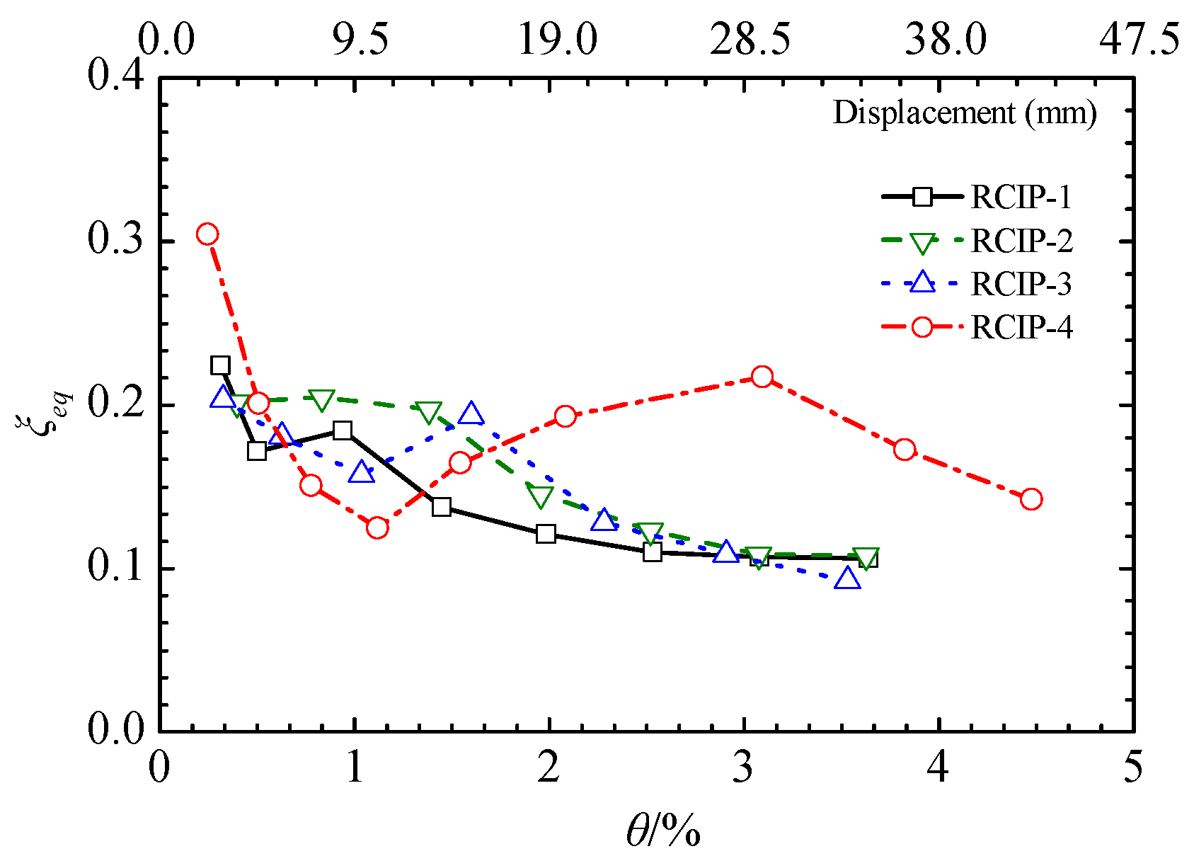
3.7. Energy Dissipation Capacity
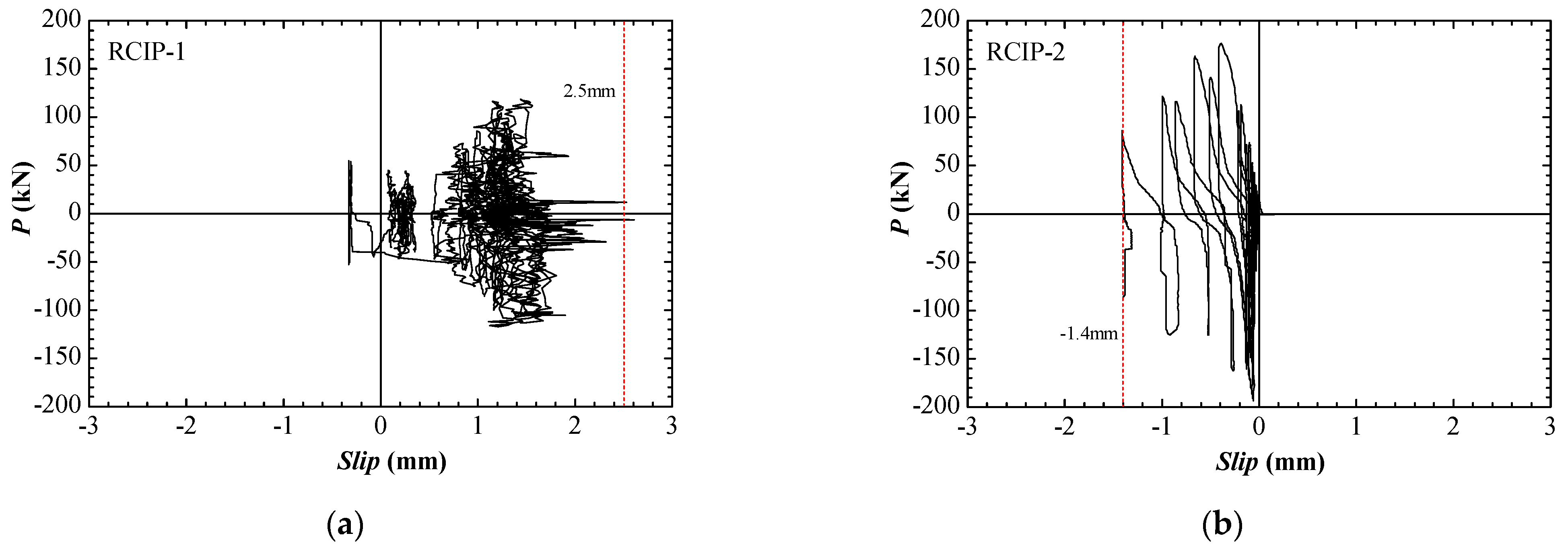
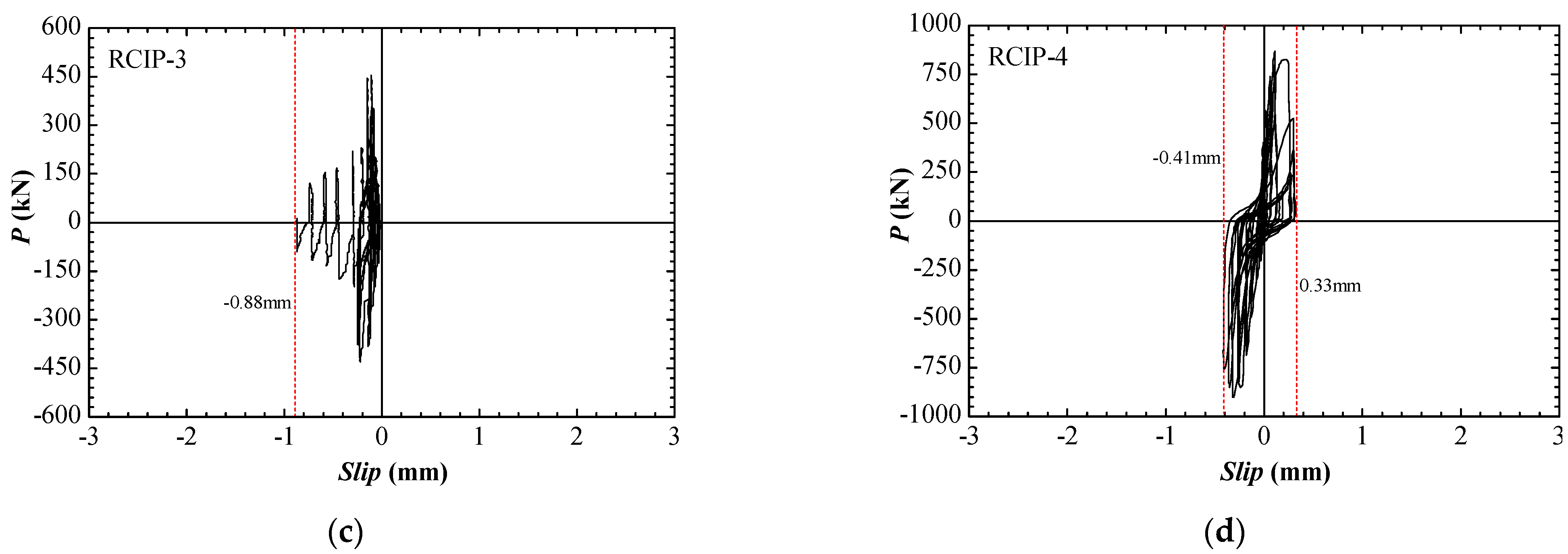
The energy dissipation capacity of a structure or member can be evaluated based on the area enclosed by the first load versus the drift cycle at different loading drift levels. The first single hysteretic energy for each specimen was calculated and plotted (Figure 16). When the drift ratio was lower than 0.3%, only minor cracks were formed, and the hysteretic loops of all specimens were very narrow. Moreover, the hysteretic energy consumption from the first cycle was limited. After the drift ratio exceeded 0.3%, the hysteretic energy of each specimen gradually increased, owing to an increase in the number of cracks, steel rebar yielding, concrete spalling in the CVSs and CHSs, and plastic hinge formation at both slit wall ends. The maximum hysteretic energy of the single cycle of RCIP-1 was 1.14 kN·m; however, that of RCIP-2 was 2.21 kN·m, which was 1.94 times that of RCIP-1. Because the same concrete strength was employed, the use of CVSs increased the lateral strength, increasing the first-cycle hysteretic energy of RCIP-2. The RC panel of RCIP-3 had CHSs, and the nature and function of the CHSs were similar to the CVSs of RCIP-2. However, because high-strength concrete was used, RCIP-3 achieved a considerably high lateral load, and the maximum hysteretic energy of its first single-cycle reached 4.55 kN·m. For RCIP-4, which had a relatively long span and high concrete strength, its lateral strength was the highest, and its maximum single-cycle hysteretic energy was 17.01 kN·m. The single-cycle hysteretic energy of RCIP-4 sharply increased before the drift ratio reached 2% and then declined rapidly (Figure 16), indicating that the RC panel was damaged severely under subsequent loading cycles. This behavior was consistent with the strength degradation trend.
The equivalent viscous damping ratio, ξeq, is used to evaluate the hysteretic loop shape of a structure or component. Figure 17 shows the calculating diagram for the calculated equivalent viscous damping ratio, which is expressed as follows:
ξ eq = S ( ABC + ADC ) 2 π S ( Δ OBE + Δ ODF )
where ξeq is the equivalent viscous damping ratio, S(ABC+ADC) is the area enclosed by the hysteretic loop, and S(ΔOBE+ΔODF) is the sum of areas of triangles OBE and ODF.
All specimens subjected to lateral shear exhibited pinching hysteretic loops (Figure 18), and their energy dissipation capacities were low. At the peak load, i.e., a drift ratio of approximately 1%, the equivalent viscous damping ratios of all specimens ranged from 0.12 to 0.2. The relative parameters, including the slit type, concrete strength, and height-to-span ratio, slightly influenced the hysteretic loop shape and energy dissipation capacity of the RC panel. Therefore, when the RC panels are used to retrofit an existing or damaged structure, the main objective is to increase the lateral strength and stiffness.

3.8. Interface Slip

LVDTs were installed to record the interface slip data and evaluate the interface slip between the RC panel and the surrounding steel beam. Figure 19 shows the curves for the lateral load versus top interface slip of all specimens. The maximum interface slips of RCIP-1 and RCIP-2 were 2.5 and 1.4 mm, respectively, which were relatively more extended than those of other specimens (Figure 19). The low-strength concrete application resulted in severe crushing at the root of the steel channel connectors and the development of a relatively extended interface slip. When high-strength concrete was used in RCIP-3 and RCIP-4, the concrete at the connector root was not crushed easily, and the recorded maximum interface slips were 0.9 and 0.5 mm, respectively. During the entire loading process, the shear connectors could reliably transfer the lateral load from the steel beam to the RC panel, and the tiny interface slips could be ignored. However, according to a previous experimental study [3], the shear connectors along the steel beam must possess a sufficient safety reserve to resist lateral design shear and prevent fracturing. Therefore, the number of shear connectors placed along the wall and steel beam should be determined based on the lateral design shear to ensure the effective combination of the RC panel and the surrounding steel frame.

4. Conclusions

In this study, four two-side-connected specimens at a one-third scale were designed and subjected to cyclic lateral loads to investigate the performance of RC panels. The behaviors of these specimens were compared, and the following conclusions were drawn.
(1)
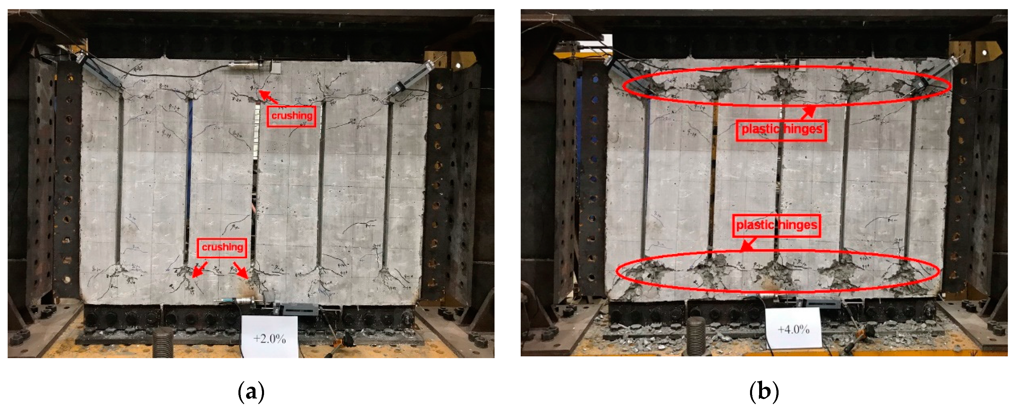
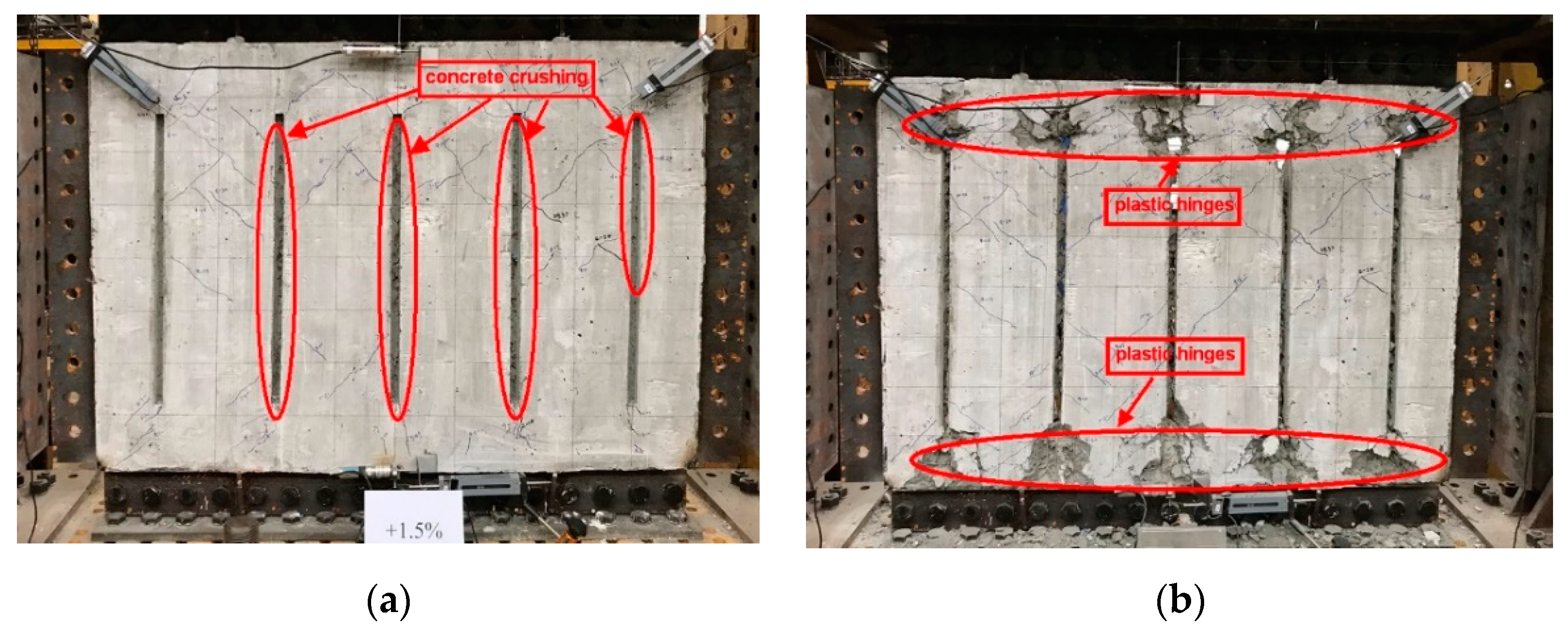
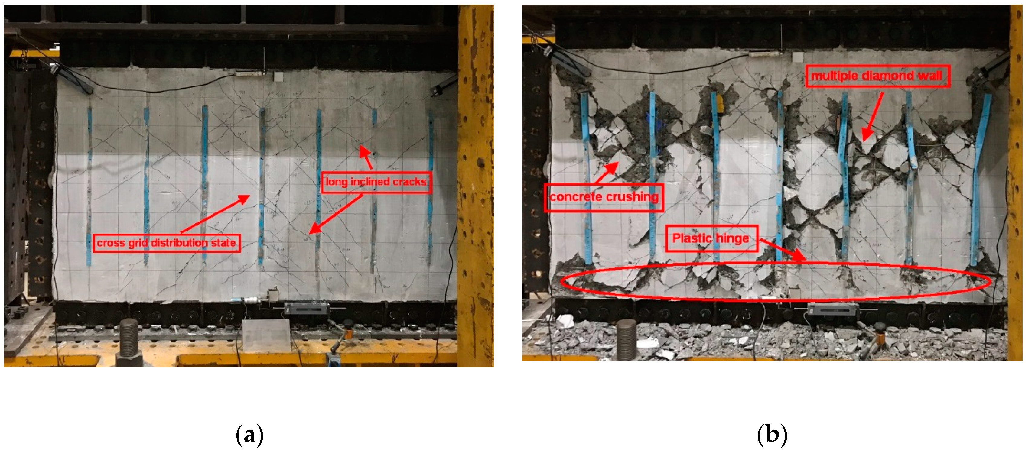
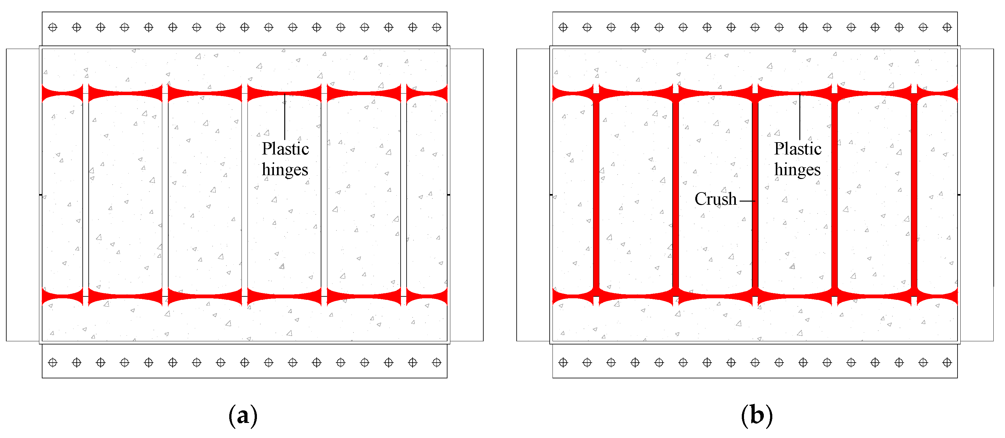
The RCIP with penetrated slits, i.e., specimens RCIP-1 and RCIP-4, experienced ductile failure with the formation of flexural plastic hinges at both slit wall ends and the concrete strength and height-to-span ratio had no significant effect on the failure mode. The RCIPs with CVSs (RCIP-2) and CHSs (RCIP-3) showed a similar two-stage failure mode. During the first stage, the CVSs and CHSs were crushed. During the second stage, the main deformation mode changed from shear to flexure, and flexural plastic hinges were formed at slit wall ends.
(2)
The hysteretic loop shape of the two-side-connected RC panels showed significantly pinched and limited energy dissipation capacity, and the corresponding equivalent viscous damping ratios were lower than 0.2.
(3)
The RC panels had penetrated slits, CVSs, and CHSs, and they exhibited moderate deformability and ductility under cyclic shear, and the average ultimate drift ratios ranged from 1.41% to 1.99%. The lowest average ductility ratio was 2.48. The RC panels with CVSs and CHSs obtained a much larger initial lateral stiffness and lateral load-bearing capacity than that with penetrated slits.
(4)
With an increase in the concrete strength, the initial lateral stiffness and lateral load-bearing capacity of the RC panel increased.
(5)
At the same story height, the initial lateral stiffnesses and lateral load-bearing capacities of the RC panels with penetrated slits increased with increasing height-to-span ratios. However, their strength degradation became severe, and their deformation capacity and ductility decreased to some extent.
Therefore, according to the current research results, RC panels with CVSs and CHSs are recommended to serve as the lateral load-resisting component for retrofitting ancient concrete or steel frames.

Author Contributions

Conceptualization, resources, project administration, funding acquisition, supervision, writing—review & editing, G.S.; investigation, data curation, writing—original draft, F.L.; investigation, data curation, Q.Z. All authors have read and agreed to the published version of the manuscript.

Funding

This study was supported by the Scientific Research Fund of Institute of Engineering Mechanics-China Earthquake Administration (Grant No.2020EEEVL0416), National Natural Science Foundation of China (Grant No. 51108292), and National Natural Science Foundation of China in Colleges and University of Jiangsu Province (Grant 17KJA560003).

Institutional Review Board Statement

Not applicable.

Data Availability Statement

Not applicable.

Conflicts of Interest

The authors declare no conflict of interest.

References

  1. Stafford-Smith, B. Behavior of Square Infilled Frames. J. Strut. Div. 1966, 92, 381–403. [Google Scholar] [CrossRef]
  2. Mallick, D.V.; Severn, R.T. Dynamic Characteristics of Infilled Frames. Proc. Inst. Civ. Eng. 1968, 39, 261–287. [Google Scholar] [CrossRef]
  3. Liauw, T.C. Test on Multistory Infilled Frames Subject to Dynamic Lateral Loading. ACI. J. 1979, 76, 551–564. [Google Scholar]
  4. Makino, M.; Kawano, A.; Kurobane, Y.; Saisho, M.; Yoshinaga, K. An investigation for the design of framed structures with infill walls. In Proceedings of the Seventh World Conference on Earthquake Engineering, Istanbul, Turkey, 8–13 September 1980; Volume 4, pp. 369–372. [Google Scholar]
  5. Liauw, T.C.; Kwan, K.H. Static and Cyclic Behavior of Multistory Infilled Frames with Different Interface Conditions. J. Sound. Vib. 1985, 99, 275–283. [Google Scholar] [CrossRef]
  6. Kwan, K.H.; Xia, J.Q. Shake-table Tests of Large-scale Shear Wall and Infilled Frame Models. Proc. Inst. Civ. Eng. Struct. Buid. 1995, 110, 66–77. [Google Scholar] [CrossRef] [Green Version]
  7. Hajjar, J.F. Composite Steel and Concrete Structural Systems for Seismic Engineering. J. Constr. Steel Res. 2002, 58, 703–723. [Google Scholar] [CrossRef]
  8. Tong, X.T.; Hajjar, J.F.; Schultz, A.E.; Shield, C.K. Cyclic Behavior of Steel Frame Structures with Composite Reinforced Concrete Infill Walls and Partially-restrained Connections. J. Constr. Steel Res. 2005, 61, 531–552. [Google Scholar] [CrossRef]
  9. Sun, G.H.; He, R.Q.; Gu, Q.; Fang, Y.Z. Cyclic Behavior of Partially-restrained Steel Frame with RC Infill Walls. J. Constr. Steel Res. 2011, 67, 1821–1834. [Google Scholar] [CrossRef]
  10. Peng, X.T.; Gu, Q. Seismic Behavior Analysis for Composite Structures of Steel Frame-reinforced Concrete Infill Wall. Struct. Des. Tall. Spec. 2013, 22, 831–846. [Google Scholar] [CrossRef]
  11. Sun, G.H.; Yang, W.C.S.; Gu, Q.; DesRoches, R.; Fang, Y.Z. Cyclic Test of Steel Frames with Concealed Vertical Slits in Reinforced Concrete Infill Wall. J. Struct. Eng. 2017, 143, 04017150. [Google Scholar] [CrossRef]
  12. Hou, H.T.; Chou, C.C.; Zhou, J.; Wu, M.L.; Qu, B.; Ye, H.D.; Liu, H.N.; Li, J.J. Cyclic Tests of Steel Frames with Composite Lightweight Infill Walls. Earthq. Struct. 2016, 10, 163–178. [Google Scholar] [CrossRef]
  13. Dall’Asta, A.; Leoni, G.; Morelli, F.; Salvatore, W.; Zona, A. An Innovative Seismic-resistant Steel Frame with Reinforced Concrete Infill Walls. Eng. Struct. 2017, 141, 144–158. [Google Scholar] [CrossRef]
  14. Olsen, E.C.; Billington, S.L. Cyclic Response of Precast High-performance Fiber-reinforced Concrete Infill Panels. ACI. Struct. J. 2011, 108, 51–60. [Google Scholar]
  15. Lignos, D.G.; Moreno, D.M.; Billington, S.L. Seismic Retrofit of Steel Moment-resisting Frames with High-performance Fiber-reinforced Concrete Infill Panels: Large-scale Hybrid Simulation Experimentas. J. Struct. Eng. 2014, 140, 04013072. [Google Scholar] [CrossRef]
  16. Muto, K.; Ohmori, N.; Takahashi, T. Study on Slitted Walls. Concr. J. 1974, 12, 15–25. (In Japanese) [Google Scholar]
  17. Lian, X.F.; Zou, C.Y. Test Research on the Working Behavior of RC Shear Panels with Vertical Seams under Low-cyclic Loading. J. Harbin Univ. Archit. Eng. 1996, 29, 31–36. [Google Scholar]
  18. Ye, L.P.; Wang, Z.H.; Kang, S.; Zhao, W.H.; Zeng, Y. Seismic Behavior and Analysis of Dual Function Slitted Shear Wall. J. Asian Archit. Build. 2002, 1, 29–37. [Google Scholar] [CrossRef]
  19. Zhao, W.; Tong, G.S.; Yang, Q.Y. Experimental Study on Seismic Behavior of Steel Frame with Prefabricated Reinforced Concrete Infill Slit Shear Walls. J. Build. Struct. 2013, 33, 140–146. (In Chinese) [Google Scholar]
  20. Sun, G.H.; Li, Q.C.; Gu, Q.; Yang, W.X. Performance Level Thresholds and Damage Evaluation for Composite Partially-restrained Steel Frame-reinforced Concrete Infill Wall with Concealed Vertical Slits. Bull. Earthq. Eng. 2017, 15, 3639–3672. [Google Scholar] [CrossRef]
  21. Sun, G.H.; Gu, Q.; Li, Q.C.; Fang, Y.Z. Experimental and Numerical Study on the Hysteretic Behavior of Composite Partially Restrained Steel Frame Reinforced Concrete Infill Walls with Vertical Slits. Bull. Earthq. Eng. 2018, 16, 1245–1272. [Google Scholar] [CrossRef]
  22. Wang, W.; Wang, X.X. Experimental and Numerical Study on Concentrated-hollow RC Shear Walls. Eng. Struct. 2021, 242, 112570. [Google Scholar] [CrossRef]
  23. FEMA 461. Interim Protocols for Determining Seismic Performance Characteristics of Structural and Nonstructural Components through Laboratory Testing; FEMA461 Draft Document; Federal Emergency Management Agency: Washington, DC, USA, 2007. [Google Scholar]
  24. FEMA 273. NEHRP Commentary on the Guidelines for the Rehabilitation of Buildings; Federal Emergency Management Agency: Washington, DC, USA, 1996. [Google Scholar]
Figure 1. General description of test specimens: (a) RCIP-1–3 and (b) RCIP-4 (dimensions in mm).
Buildings 12 00016 g001
Figure 2. Steel reinforcement details of test specimens: (a) RCIP-1–3; (b) RCIP-4; (c) slit details (dimensions in mm).
Buildings 12 00016 g002
Figure 3. The test setup.
Buildings 12 00016 g003
Figure 4. Arrangement of the LVDTs. Note: The displacement range of D1–D6 was 100 mm, and that of D7–D9 was 50 mm.
Buildings 12 00016 g004
Figure 5. The loading protocol.
Buildings 12 00016 g005
Figure 6. Images of RCIP-1 in different states: (a) at a drift ratio of 2%; (b) front view after the test.
Buildings 12 00016 g006
Figure 7. Images of RCIP-2 in different states: (a) at a drift ratio of 1.5%; (b) front view after the test.
Buildings 12 00016 g007
Figure 8. Images of RCIP-3 in different states: (a) at a drift ratio of 2%; (b) front view after the test.
Buildings 12 00016 g008
Figure 9. Images of RCIP-4 in different states: (a) at a drift ratio of 1.5%; (b) front view after the test.
Buildings 12 00016 g009
Figure 10. Failure modes of the RC panels with different slit types: (a) failure mode I; (b) failure mode II.
Buildings 12 00016 g010
Figure 11. Hysteretic lateral load–drift ratio response of the tested specimens: (a) RCIP-1; (b) RCIP-2; (c) RCIP-3; (d) RCIP-4.
Buildings 12 00016 g011aBuildings 12 00016 g011b
Figure 12. Method of determining the key characteristic points of the tested specimens reprinted form ref. [24].
Buildings 12 00016 g012
Figure 13. Lateral load–drift ratio envelope curves for the tested specimens.
Buildings 12 00016 g013
Figure 14. Lateral stiffness degradation of test specimens: (a) initial lateral stiffness; (b) lateral stiffness degradation curves.
Buildings 12 00016 g014
Figure 15. Lateral strength degradation curves for the tested specimens.
Buildings 12 00016 g015
Figure 16. Comparison of single-cycle hysteretic energy at each loading level.
Buildings 12 00016 g016
Figure 17. Calculating diagram of the equivalent viscous damping ratio.
Buildings 12 00016 g017
Figure 18. Equivalent viscous damping ratios of the tested specimens.
Buildings 12 00016 g018
Figure 19. Curves for lateral load versus top interface slip: (a) RCIP-1; (b) RCIP-2; (c) RCIP-3; (d) RCIP-4.
Buildings 12 00016 g019aBuildings 12 00016 g019b
Table 1. Details of the test specimens.
SpecimenSlit TypeThickness of Unpenetrated Slit, mmConcrete GradeHeight-to-Span Ratio
RCIP-1Penetrated slit0C300.7
RCIP-2Concealed vertical slit30C300.7
RCIP-3Concealed hollow slit40C300.7
RCIP-4Penetrated slit0C300.54
Table 2. Material properties of the steel and steel bars.
Steel or RebarsActual Thickness or Diameter, mmYield Strength fy, MPaTensile Strength fu, MPaElongation at Fracture ε, %
Channel web5.10333.4405.624.3
4 mm steel wire4.17270.5465.211.3
6.5 mm steel rebar6.47379.2538.026.4
Table 3. Characteristic lateral loading responses.
SpecimenLoading DirectionPy (kN)θy (%)Pm (kN)θm (%)Pu (kN)θu (%)μ
RCIP-1+73.810.24118.541.31100.761.998.29
78.000.35117.370.9399.761.985.66
Average75.910.30117.961.12100.261.996.73
RCIP-2+130.750.42176.620.71150.131.453.45
122.970.13193.570.84164.531.3710.54
Average126.860.28185.010.78157.331.415.13
RCIP-3+330.890.46453.870.87385.791.713.72
285.490.38430.301.03365.761.584.16
Average308.190.42442.090.95375.781.653.92
RCIP-4+651.110.93868.141.48737.922.192.35
624.200.55900.451.11765.381.482.69
Average637.660.74884.301.30751.651.842.48
Py is the yield load; θy is the yield drift ratio; Pm is the peak load; θm is the peak drift ratio; Pu is the ultimate load corresponding to the load at which the specimen failed or dropped to 0.85Pmax; θu is the ultimate drift ratio; μ is the ductility ratio.
Publisher’s Note: MDPI stays neutral with regard to jurisdictional claims in published maps and institutional affiliations.

