
Analysis of Seismic Action on the Tie Rod System in Historic Buildings Using Finite Element Model Updating


Abstract
1. Introduction
2. Experimental Analysis
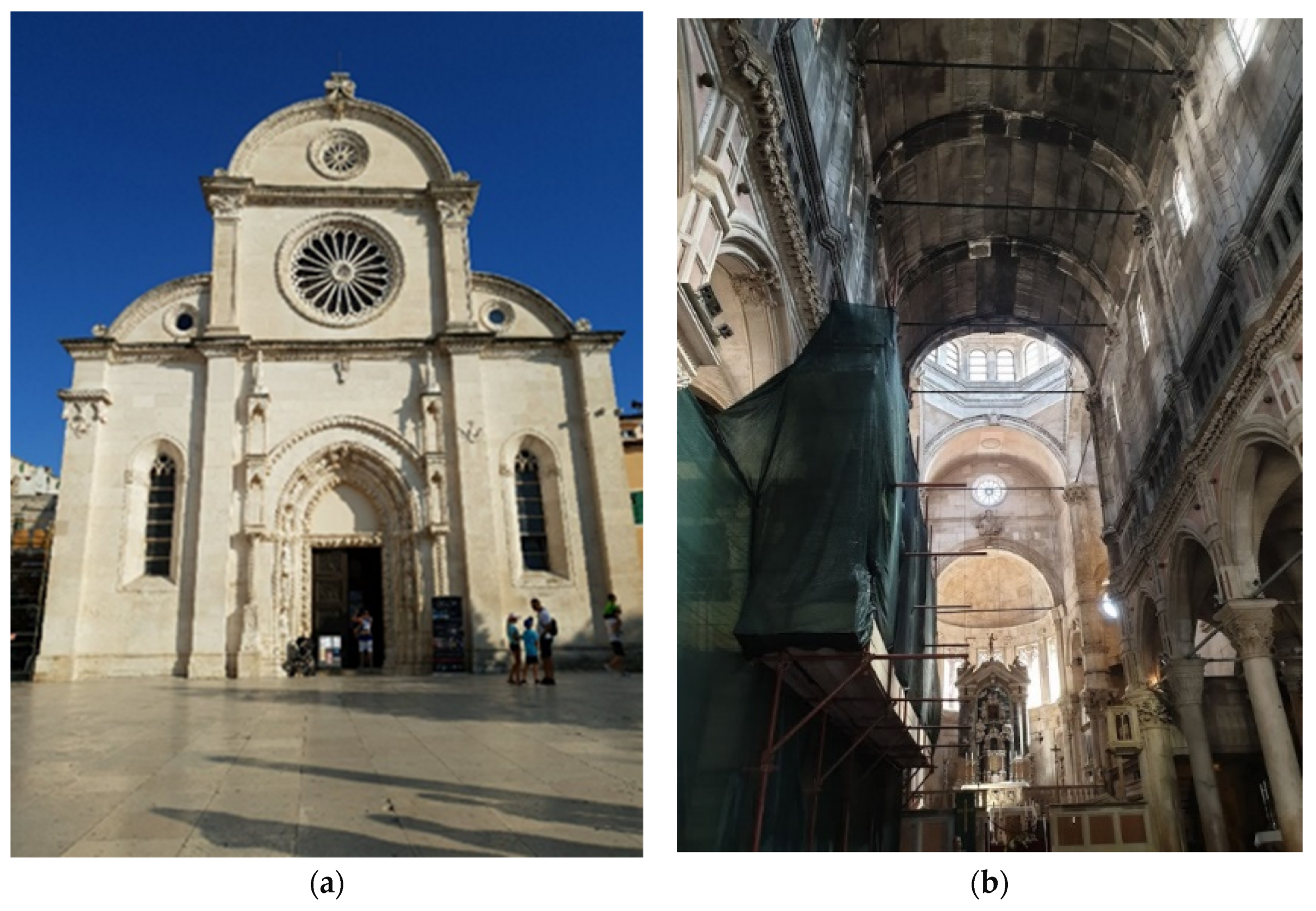
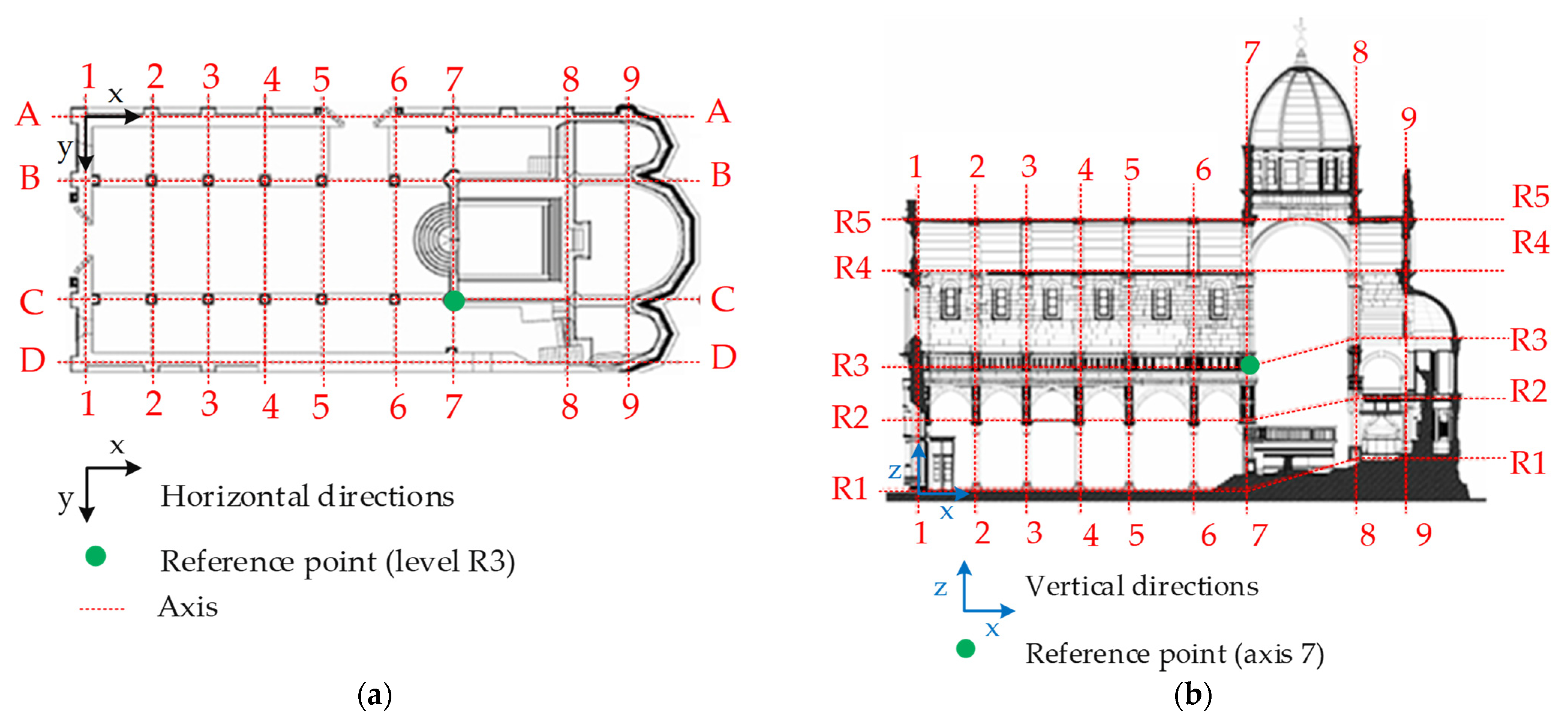
2.1. Experimental Investigation of the Structure
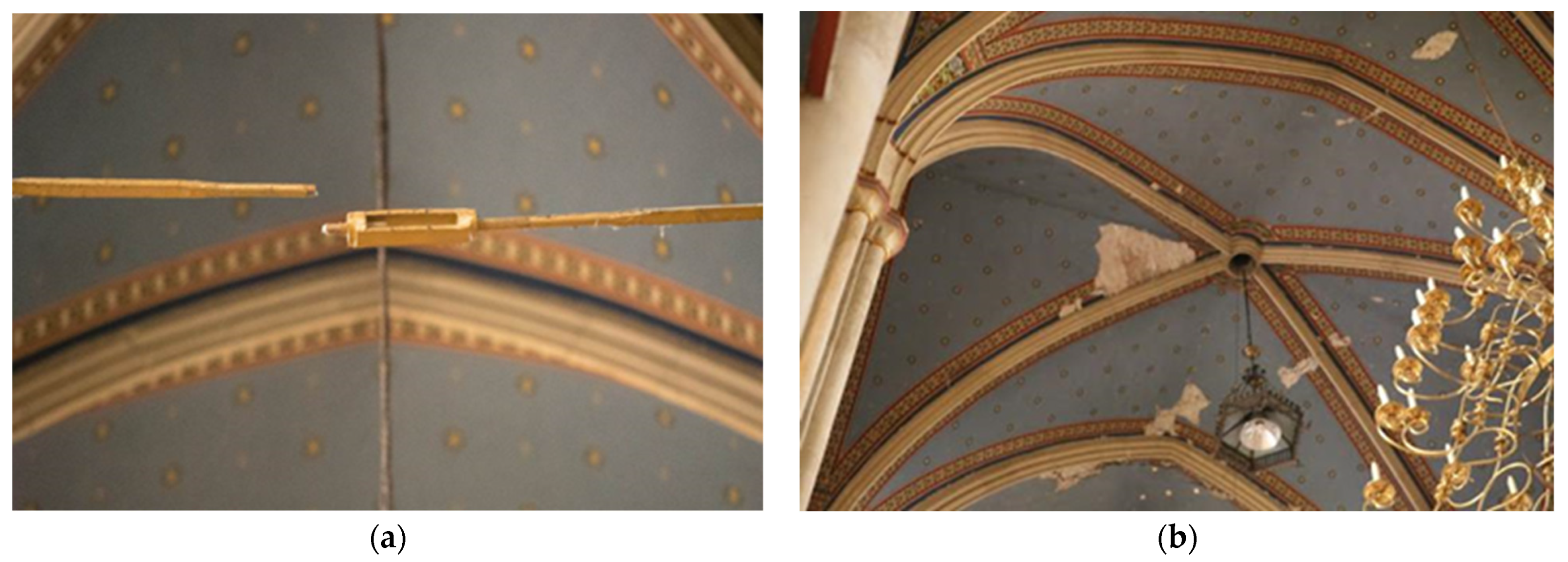
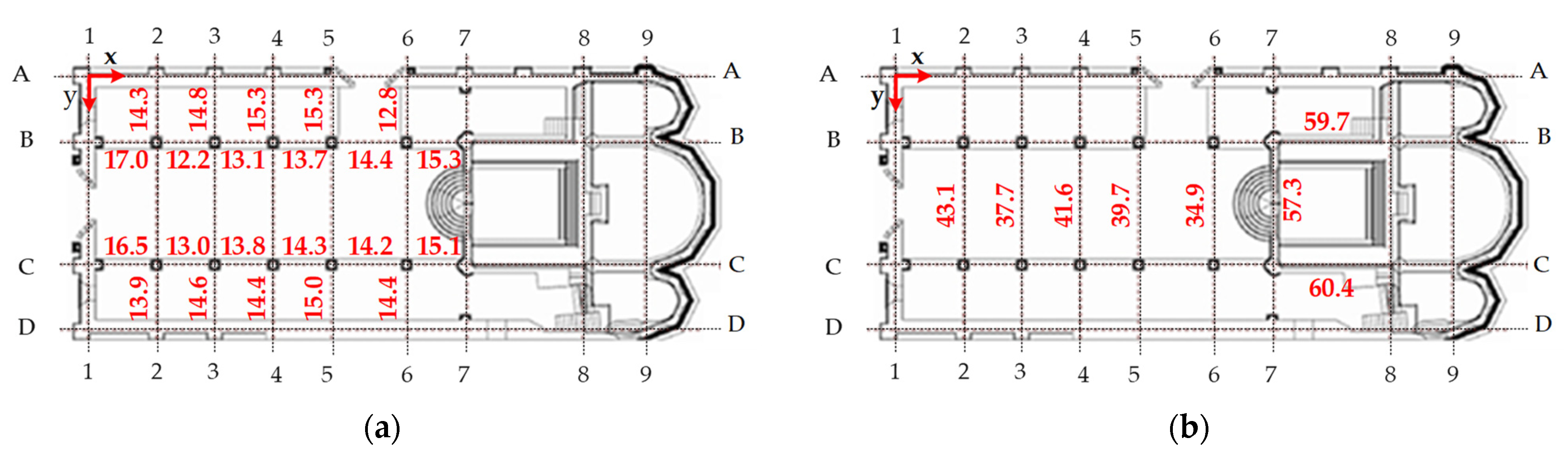
2.2. Experimental Investigation of Tie Rods
3. Numerical Analysis
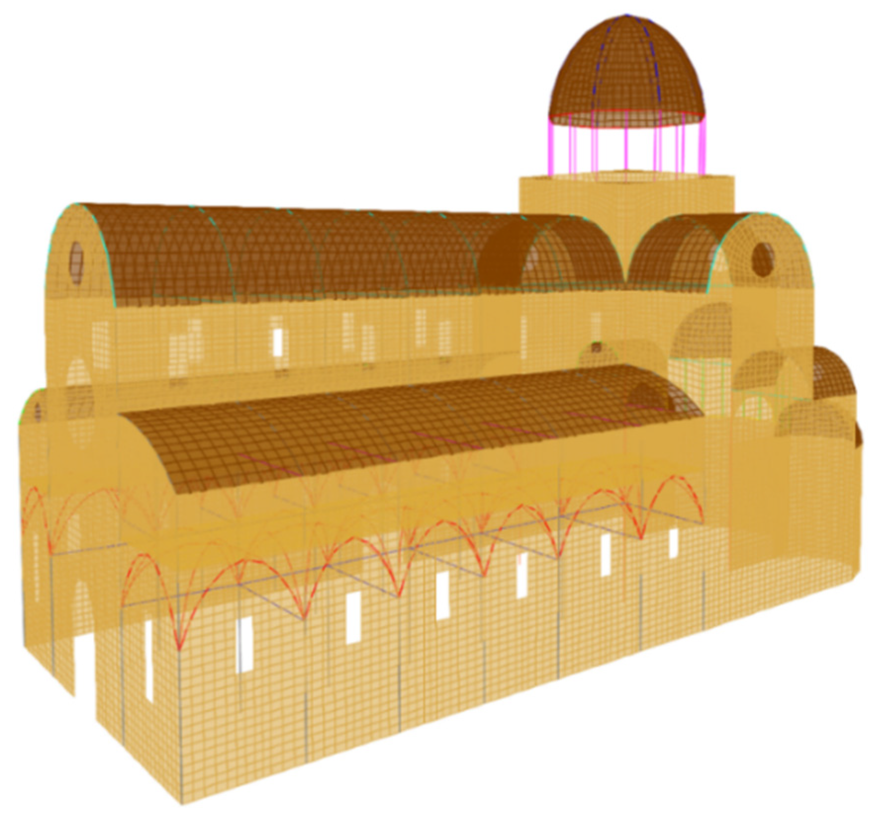
3.1. Initial Numerical Model of the Cathedral
3.2. Results of the Initial Numerical Model of the Cathedral
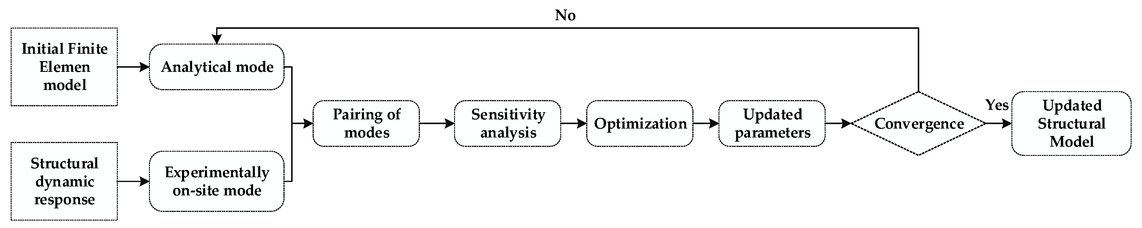
4. Finite Element Model Updating
4.1. Manual FEMU
4.2. Evaluation of the Updated Numerical Model Using Modal Assurance Factor Criteria (MAC)
4.3. Results of the Evaluation of the Numerical Model
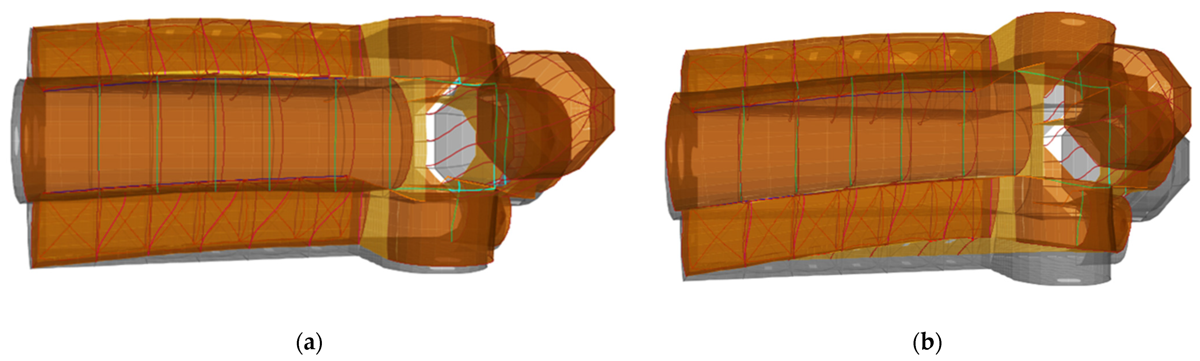
5. Analysis of Seismic Action of the Tie Rod Systems
6. Discussion and Conclusions
Author Contributions
Funding
Institutional Review Board Statement
Informed Consent Statement
Data Availability Statement
Conflicts of Interest
References
- Battista, L.A. De re Aedificatoria. 1565. Available online: https://warburg.sas.ac.uk/pdf/cnh1015b2214989.pdf (accessed on 23 August 2021).
- Li, S.; Reynders, E.; Maes, K.; De Roeck, G. Vibration-based estimation of axial force for a beam member with uncertain boundary conditions. J. Sound Vib. 2013, 332, 795–806. [Google Scholar] [CrossRef]
- Li, D.S.; Yuan, Y.Q.; Li, K.P.; Li, H.N. Experimental axial force identification based on modified Timoshenko beam theory. Struct. Monit. Maint. 2017, 4, 153–173. [Google Scholar] [CrossRef]
- Li, S.; Josa, I.; Cavero, E. Post Earthquake Evaluation of Axial Forces and Boundary Conditions for High-Tension. In Proceedings of the 16th World Conference of Earthquake, Santiago, Chile, 3–9 January 2017. [Google Scholar]
- Tullini, N. Bending tests to estimate the axial force in slender beams with unknown boundary conditions. Mech. Res. Commun. 2013, 53, 15–23. [Google Scholar] [CrossRef]
- Calderini, C.; Piccardo, P.; Vecchiattini, R. Experimental Characterization of Ancient Metal Tie-Rods in Historic Masonry Buildings. Int. J. Arch. Heritage 2019, 13, 425–437. [Google Scholar] [CrossRef]
- Duvnjak, I.; Damjanović, D.; Krolo, J. Structural health monitoring of cultural heritage structures: Applications on Peristyle of Diocletian’s palace in Split. In Proceedings of the 8th European Workshop on Structural Health Monitoring, EWSHM 2016, Bilbao, Spain, 5–8 July 2016; Volume 4. [Google Scholar]
- Collini, L.; Garziera, R.; Riabova, K. Vibration Analysis for Monitoring of Ancient Tie-Rods. Shock. Vib. 2017, 2017, 1–11. [Google Scholar] [CrossRef]
- Gentilini, C.; Marzani, A.; Mazzotti, M. Nondestructive characterization of tie-rods by means of dynamic testing, added masses and genetic algorithms. J. Sound Vib. 2013, 332, 76–101. [Google Scholar] [CrossRef]
- Duvnjak, I.; Ereiz, S.; Damjanović, D.; Bartolac, M. Determination of Axial Force in Tie Rods of Historical Buildings Using the Model-Updating Technique. Appl. Sci. 2020, 10, 6036. [Google Scholar] [CrossRef]
- Friswell, M.; Mottershead, J.E. Finite Element Model Updating in Structural Dynamics; Springer: Dordrecht, The Netherlands, 1996; pp. 56–155. [Google Scholar]
- Ismail, Z.; Kuan, K.K.; Yee, K.S.; Chao, O.Z. Examining the trend in loss of flexural stiffness of simply supported RC beams with various crack severity using model updating. Measurement 2014, 50, 43–49. [Google Scholar] [CrossRef]
- Oh, B.K.; Kim, D.; Park, H.S. Modal Response-Based Visual System Identification and Model Updating Methods for Building Structures. Comput. Civ. Infrastruct. Eng. 2016, 32, 34–56. [Google Scholar] [CrossRef]
- Zhou, L.; Wang, L.; Chen, L.; Ou, J. Structural finite element model updating by using response surfaces and radial basis functions. Adv. Struct. Eng. 2016, 19, 1446–1462. [Google Scholar] [CrossRef]
- Kim, S.; Kim, N.; Park, Y.-S.; Jin, S.-S.; Park, K.; Jin, A. Sequential Framework for Improving Identifiability of FE Model Updating using Static and Dynamic Data. Sensors 2019, 19, 5099. [Google Scholar] [CrossRef]
- Ye, S.; Lai, X.; Bartoli, I.; Aktan, A.E. Technology for condition and performance evaluation of highway bridges. J. Civ. Struct. Health Monit. 2020, 10, 573–594. [Google Scholar] [CrossRef]
- Shahbaznia, M.; Dehkordi, M.R.; Mirzaee, A. An Improved Time-Domain Damage Detection Method for Railway Bridges Subjected to Unknown Moving Loads. Period. Polytech. Civ. Eng. 2020, 64, 928–938. [Google Scholar] [CrossRef]
- Luo, X.; Li, X.; Fu, X.; Gu, L. Research on Bridge Structural Health Assessment Based on Finite Element Analysis. Teh. Vjesn.-Tech. Gaz. 2020, 27, 96–105. [Google Scholar] [CrossRef]
- Cui, Y.; Lu, W.; Teng, J. Updating of structural multi-scale monitoring model based on multi-objective optimisation. Adv. Struct. Eng. 2019, 22, 1073–1088. [Google Scholar] [CrossRef]
- Nguyen, A.; Kodikara, K.T.L.; Chan, T.; Thambiratnam, D. Deterioration assessment of buildings using an improved hybrid model updating approach and long-term health monitoring data. Struct. Health Monit. 2018, 18, 5–19. [Google Scholar] [CrossRef]
- Pachón, P.; Castro, R.; García, M.E.P.; Compán, V.; Puertas, E.E. Torroja’s bridge: Tailored experimental setup for SHM of a historical bridge with a reduced number of sensors. Eng. Struct. 2018, 162, 11–21. [Google Scholar] [CrossRef]
- Altunişik, A.C.; Okur, F.Y.; Genç, A.F.; Günaydin, M.; Adanur, S. Automated Model Updating of Historical Masonry Structures Based on Ambient Vibration Measurements. J. Perform. Constr. Facil. 2018, 32, 04017126. [Google Scholar] [CrossRef]
- Cheng, X.; Dong, J.; Han, X.; Fei, Q. Structural Health Monitoring-Oriented Finite-Element Model for a Large Transmission Tower. Int. J. Civ. Eng. 2018, 16, 79–92. [Google Scholar] [CrossRef]
- Venanzi, I.; Kita, A.; Cavalagli, N.; Ierimonti, L.; Ubertini, F. Earthquake-induced damage localization in an historic masonry tower through long-term dynamic monitoring and FE model calibration. Bull. Earthq. Eng. 2020, 18, 2247–2274. [Google Scholar] [CrossRef]
- Ye, X.; Chen, B. Model updating and variability analysis of modal parameters for super high-rise structure. Concurr. Comput. Pr. Exp. 2019, 31, 1–11. [Google Scholar] [CrossRef]
- Astroza, R.; Ebrahimian, H.; Li, Y.; Conte, J.P. Bayesian nonlinear structural FE model and seismic input identification for damage assessment of civil structures. Mech. Syst. Signal Process. 2017, 93, 661–687. [Google Scholar] [CrossRef]
- Moravej, H.; Chan, T.H.T.; Nguyen, K.-D.; Jesus, A. Vibration-based Bayesian model updating of civil engineering structures applying Gaussian process metamodel. Adv. Struct. Eng. 2019, 22, 3487–3502. [Google Scholar] [CrossRef]
- Tran-Ngoc, H.; Khatir, S.; De Roeck, G.; Bui-Tien, T.; Nguyen-Ngoc, L.; Wahab, M.A. Model Updating for Nam O Bridge Using Particle Swarm Optimization Algorithm and Genetic Algorithm. Sensors 2018, 18, 4131. [Google Scholar] [CrossRef]
- Nie, R.-F.; Huang, Y.-J.; Li, S.-H. In-Service Condition Assessment of Long-Span Bridges Based on Traffic Load Effects Using Monitoring Data. Staveb. Obzor-Civil Eng. J. 2018, 27, 450–457. [Google Scholar] [CrossRef]
- Naranjo-Pérez, J.; Jiménez-Alonso, J.F.; Pavic, A.; Sáez, A. Finite-element-model updating of civil engineering structures using a hybrid UKF-HS algorithm. Struct. Infrastruct. Eng. 2021, 17, 620–637. [Google Scholar] [CrossRef]
- Pacheco-Torgal, F.; Melchers, R.; Shi, X.; De Belie, N.; Van Tittelboom, K.; SaezEds, A. Eco-Efficient Repair and Rehabilitation of Concrete Infrastructure; Woodhead Publishing (Elsevier): Cambridge, UK, 2017. [Google Scholar]
- Lulić, L.; Ožić, K.; Kišiček, T.; Hafner, I.; Stepinac, M. Post-Earthquake Damage Assessment—Case Study of the Educational Building after the Zagreb Earthquake. Sustainability 2021, 13, 6353. [Google Scholar] [CrossRef]
- Livingston, R.A. Nondestructive Testing of Historic Structures. Arch. Mus. Inform. 1999, 13, 249–271. [Google Scholar] [CrossRef]
- Chastre, C.; Ludovico-Marques, M. Nondestructive testing methodology to assess the conservation of historic stone buildings and monuments. In Handbook of Materials Failure Analysis; Elsevier BV: New York, NY, USA, 2018; pp. 255–294. [Google Scholar]
- Kujawa, M.; Lubowiecka, I.; Szymczak, C. Finite element modelling of a historic church structure in the context of a masonry damage analysis. Eng. Fail. Anal. 2020, 107, 104233. [Google Scholar] [CrossRef]
- D’Ayala, D.F. Numerical Modelling of Masonry Structures. Structures & Construction in Historic Building Conservation; Wiley: Hoboken, NJ, USA, 2007; pp. 151–172. [Google Scholar] [CrossRef]
- Werkle, H. Modelling of connections between dissimilar finite element domains. Appl. Sci. 2002, 77, 78476. [Google Scholar]
- Caliò, I.; Cannizzaro, F.; Marletta, M. A Discrete Element for Modeling Masonry Vaults. Adv. Mater. Res. 2010, 133-134, 447–452. [Google Scholar] [CrossRef]
- Erenoglu, R.C.; Erenoglu, O.; Arslan, N. Accuracy Assessment of Low Cost UAV Based City Modelling for Urban Planning. Teh. Vjesn.-Tech. Gaz. 2018, 25, 1708–1714. [Google Scholar] [CrossRef]
- Mader, D.; Blaskow, R.; Westfeld, P.; Weller, C. Potential of Uav-Based Laser Scanner and Multispectral Camera Data in Building Inspection. ISPRS-Int. Arch. Photogramm. Remote. Sens. Spat. Inf. Sci. 2016, XLI-B1, 1135–1142. [Google Scholar] [CrossRef]
- Kerle, N.; Nex, F.; Gerke, M.; Duarte, D.; Vetrivel, A. UAV-Based Structural Damage Mapping: A Review. ISPRS Int. J. Geo-Inform. 2019, 9, 14. [Google Scholar] [CrossRef]
- Kuczyńska, G.; Stawska, M.; Walicka, A. Modern geodetic techniques in the monitoring of historic buildings. E3S Web Confer. 2019, 97, 04043. [Google Scholar] [CrossRef]
- Bayraktar, A.; Türker, T.; Sevım, B.; Altunişik, A.C.; Yildirim, F. Modal Parameter Identification of Hagia Sophia Bell-Tower via Ambient Vibration Test. J. Nondestruct. Eval. 2009, 28, 37–47. [Google Scholar] [CrossRef]
- Atamturktur, S.; Pavic, A.; Reynolds, P.; Boothby, T. Full-Scale Modal Testing of Vaulted Gothic Churches: Lessons Learned. Exp. Tech. 2009, 33, 65–74. [Google Scholar] [CrossRef]
- Binante, V.; Girarrdi, M.; Padovani, C.; Pasquinelli, G.; Pellegrini, D.; Porcelli, M.; Robol, L. Nosa—Itaca Documentation; Version 1.1; Istituto di Scienza e T Tecnologie dell’Informazione “Alessandro Faedo“: Pisa, Italy, 2017. [Google Scholar]
- Luong, H.T.; Zabel, V.; Lorenz, W.; Rohrmann, R.G. Vibration-based Model Updating and Identification of Multiple Axial Forces in Truss Structures. Procedia Eng. 2017, 188, 385–392. [Google Scholar] [CrossRef]
- Ebrahimian, H.; Astroza, R.; Conte, J.P.; Papadimitriou, C. Nonlinear Model Inversion Method for Joint System Parameter, Noise, and Input Identification of Civil Structures. Procedia Eng. 2017, 199, 924–929. [Google Scholar] [CrossRef]
- Ding, W.; Guo, Q. Application of Finite Element Method in Large-span Beam Bridge. In Proceedings of the 2016 International Conference on Engineering and Technology Innovations, Wuhan, China, 26–27 March 2016; p. 296. [Google Scholar] [CrossRef]
- Ereiz, S.; Duvnjak, I.; Damjanović, D.; Krolo, J.; Bartolac, M. Analysis of Seismic Action of The Tie Rod System in Historical Buildings. In Proceedings of the 1st Croatian Conference on Earthquake Engineering, Zagreb, Croatia, 22–24 March 2021; pp. 1533–1543. [Google Scholar]
- Jurić-Kačunić, D. Geotechnical Report; Department of Geotechnics, Faculty of Civil Engineering, University of Zagreb: Zagreb, Croatia, 2018. [Google Scholar]
- Allemang, R.J.; Brown, D.L. A Correlation Coefficient for Modal Vector Analysis. In Proceedings of the 1st International Modal Analysis Conference (IMAC I), Orlando, FL, USA, 8–10 November 1982; pp. 110–116. [Google Scholar]
- European Committee for Standardization (CEN). EN 1998-1:2004, Eurocode 8, Design of Structures for Earthquake Resistance, Part 1: General Rules, Seismic Actions and Rules for Buildings; CEN: Brussels, The Netherlands, 2004. [Google Scholar]


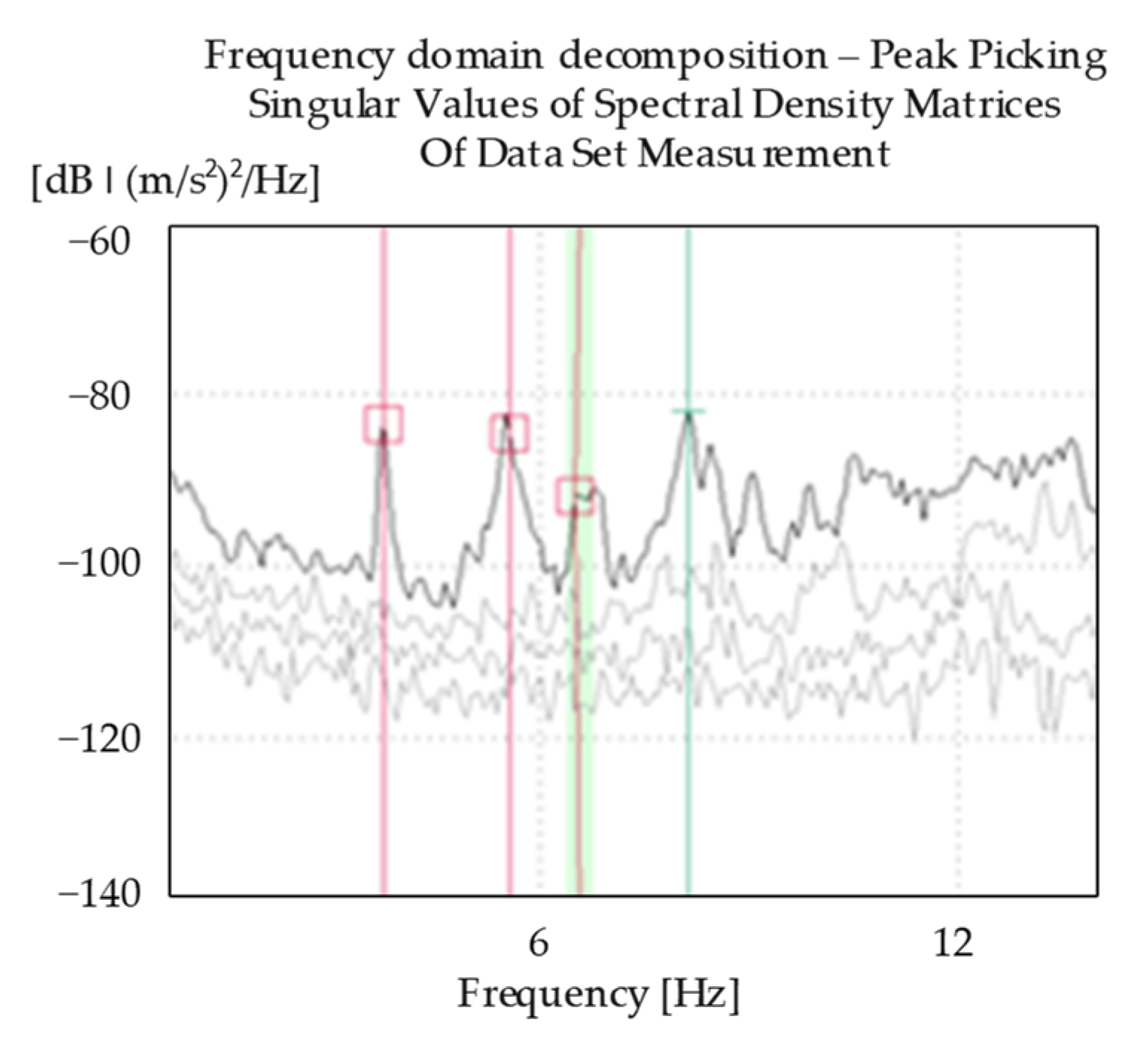
| Mode, n | Direction | |
|---|---|---|
| 1 | 3.75 | Bending around x axis, symmetrical |
| 2 | 5.55 | Bending around x axis, antimetrical |
| 3 | 5.85 | Second bending mode shape around the x axis |
| Material | Material Density, ρ (kg/m3) | Elasticity Modulus E (GPa) |
|---|---|---|
| Stone | 2491 | 20 |
| Cast Steel | 7697 | 185 |
| Aluminum | 2660 | 70 |
| Mode, n | Direction | (Hz) | (Hz) | Natural Frequency Error (%) |
|---|---|---|---|---|
| 1 | Bending around x axis, symmetrical | 3.13 | 3.75 | 16.5 |
| 2 | Bending around x axis, antimetrical | 5.14 | 5.55 | 6.5 |
| 3 | Second bending mode shape around x axis | 6.24 | 5.85 | 6.3 |
| (a) Hinge | (b) Clamped | ||||||
 |  | ||||||
| Mode, n | 1 | 2 | 3 | Mode, n | 1 | 2 | 3 |
| (GPa) | 27.5 | 26.0 | 25.5 | (GPa) | 21.5 | 24.0 | 24.5 |
| Average | 26.3 GPa | Average | 23.3 GPa | ||||
| (c) Winkler springs | |||||||
 | |||||||
| Mode, n | 1 | 2 | 3 | ||||
| (kN/m) | 15,000 | - | - | ||||
| Average | 15,000 kN/m | ||||||
| Model | Boundary Condition | (GPa) | (N/m) |
|---|---|---|---|
| 1. HBC | 26.5 | - | |
| 2. CBC | 23.2 | - | |
| 3. ELS | 25 | 15,000 |
| Numerical Model | ||
|---|---|---|
| 1. HBC | 2. CBC | 3. ELS |
 |  |  |
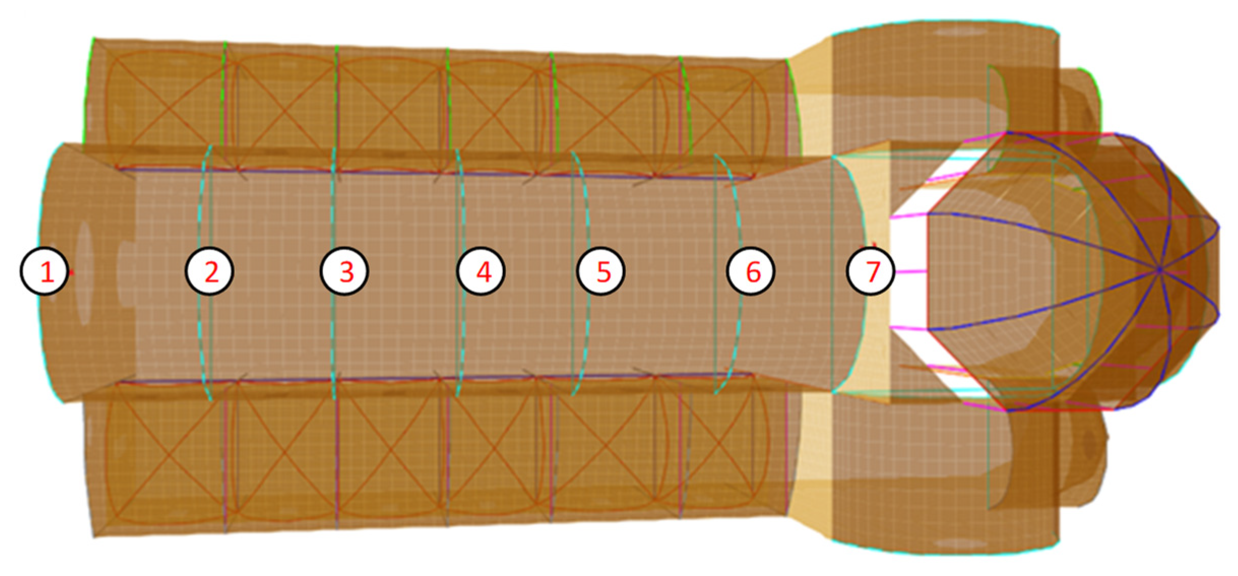
| (a) Numerically obtained normalized mode shape vector for the selected measurement points (1–7) | ||
| (b) MAC matrices for comparison of the numerically and experimentally obtained normalized mode shape vectors for the selected measurement points (1–7) | ||
 |  |  |
| (c) Graphical representation of MAC matrices for comparison of the numerically and experimentally obtained normalized mode shape vectors for the selected measurement points (1–7) | ||
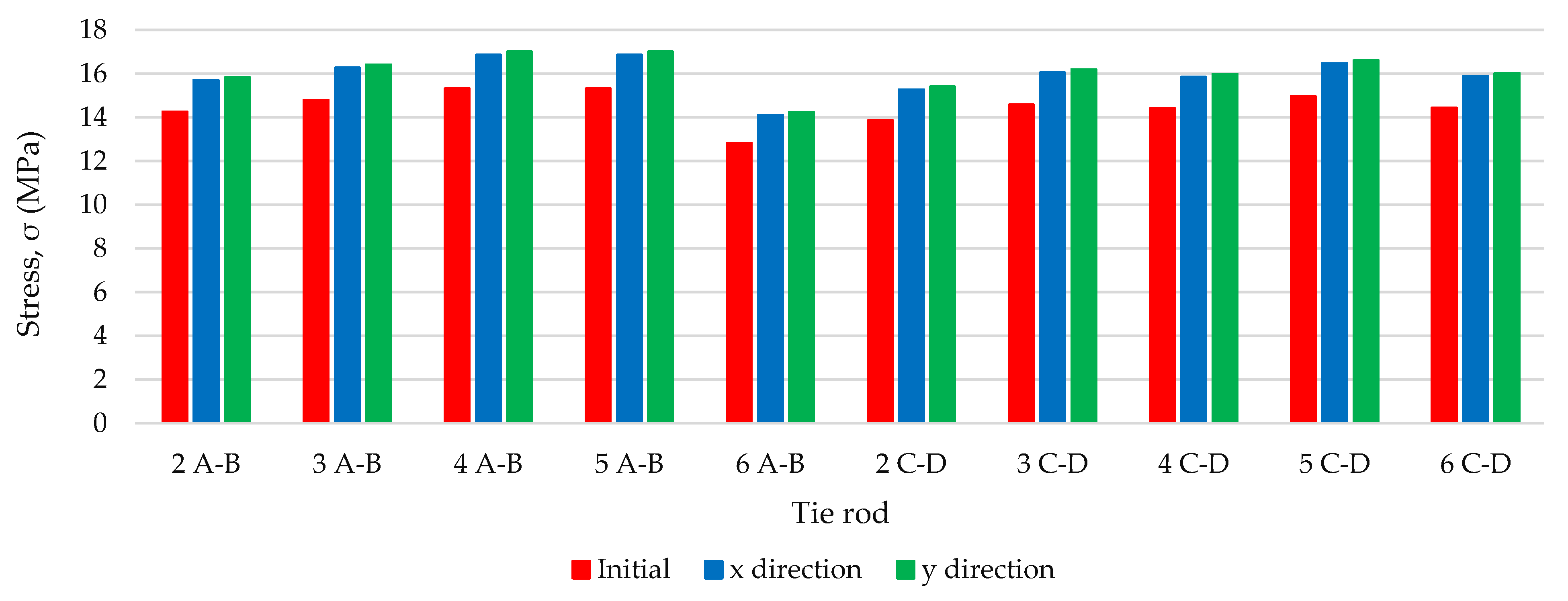
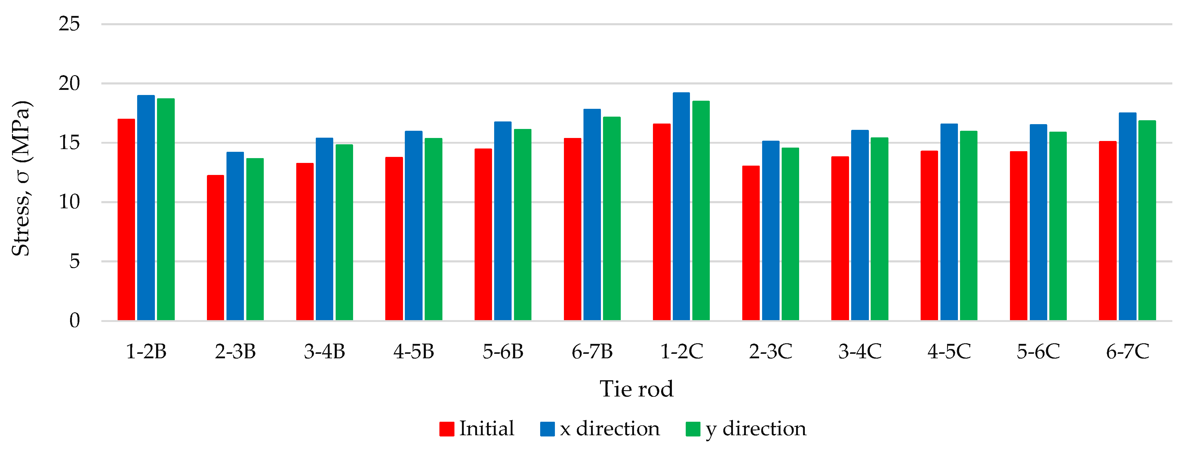
| Tie Rod | 2 A–B | 3 A–B | 4 A–B | 5 A–B | 6 A–B | 1–2 B | 2–3 B | 3–4 B | 4–5 B | 5–6 B | 6–7 B |
|---|---|---|---|---|---|---|---|---|---|---|---|
| Earthquake Direction | σn (MPa) | σn (MPa) | σn (MPa) | σn (MPa) | σn (MPa) | σn (MPa) | σn (MPa) | σn (MPa) | σn (MPa) | σn (MPa) | σn (MPa) |
| x | 15.68 | 16.26 | 16.84 | 16.84 | 14.10 | 18.92 | 14.16 | 15.36 | 15.32 | 16.72 | 17.79 |
| y | 15.83 | 16.41 | 17.00 | 17.00 | 14.23 | 18.67 | 13.62 | 14.78 | 15.93 | 16.09 | 17.11 |
| Tie rod | 2 C–D | 3 C–D | 4 C–D | 5 C–D | 6 C–D | 1–2 C | 2–3 C | 3–4 C | 4–5 C | 5–6 C | 6–7 |
| Earthquake Direction | σn (MPa) | σn (MPa) | σn (MPa) | σn (MPa) | σn (MPa) | σn (MPa) | σn (MPa) | σn (MPa) | σn (MPa) | σn (MPa) | σn (MPa) |
| x | 15.25 | 16.04 | 15.84 | 16.45 | 15.87 | 19.18 | 15.08 | 15.98 | 16.55 | 16.47 | 17.48 |
| y | 15.39 | 16.18 | 15.98 | 16.60 | 16.01 | 18.45 | 14.51 | 15.38 | 15.92 | 15.85 | 16.81 |
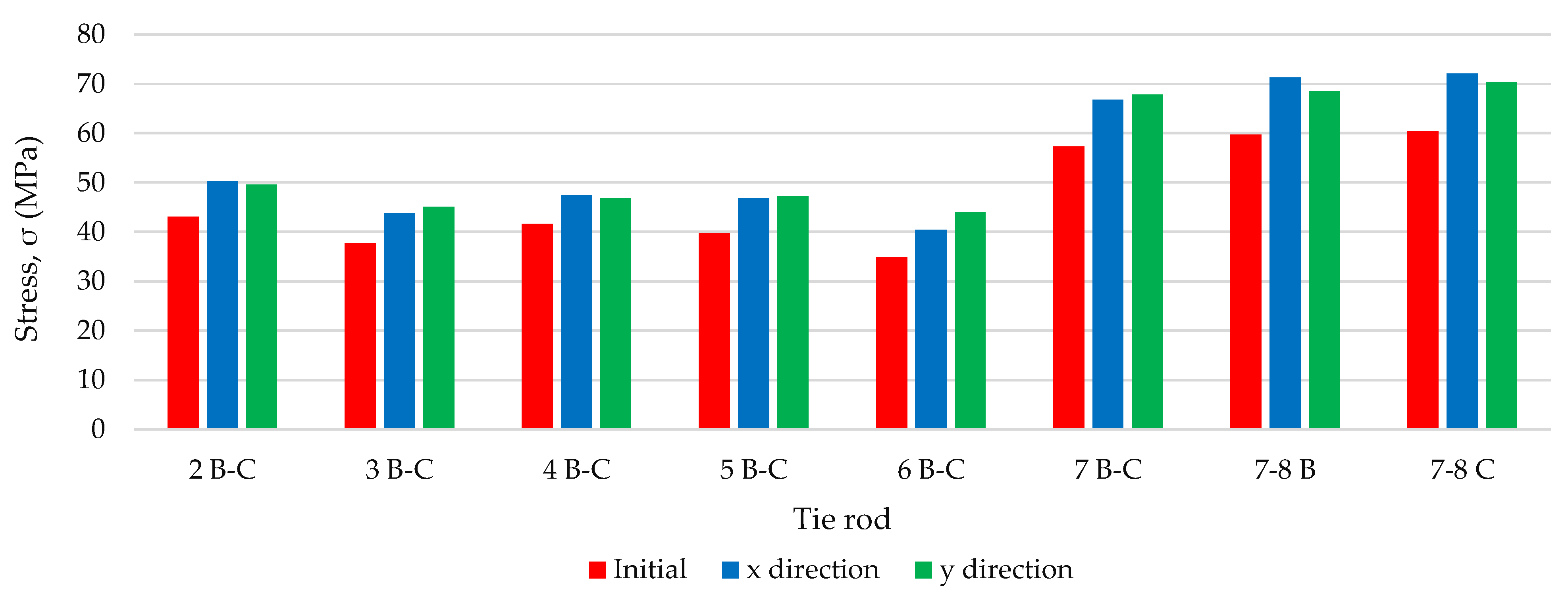
| Tie Rod | 2 B-C | 3 B-C | 4 B-C | 5 B-C | 6 B-C | 7 B-C | 7‒8 B | 7‒8 C |
|---|---|---|---|---|---|---|---|---|
| Earthquake Direction | σn (MPa) | σn (MPa) | σn (MPa) | σn (MPa) | σn (MPa) | σn (MPa) | σn (MPa) | σn (MPa) |
| x | 50.26 | 43.85 | 47.52 | 46.83 | 40.51 | 66.83 | 71.35 | 72.18 |
| y | 49.54 | 45.10 | 46.82 | 47.23 | 44.06 | 67.86 | 68.56 | 70.39 |
Publisher’s Note: MDPI stays neutral with regard to jurisdictional claims in published maps and institutional affiliations. |
© 2021 by the authors. Licensee MDPI, Basel, Switzerland. This article is an open access article distributed under the terms and conditions of the Creative Commons Attribution (CC BY) license (https://creativecommons.org/licenses/by/4.0/).
Share and Cite
Ereiz, S.; Duvnjak, I.; Damjanović, D.; Bartolac, M. Analysis of Seismic Action on the Tie Rod System in Historic Buildings Using Finite Element Model Updating. Buildings 2021, 11, 453. https://doi.org/10.3390/buildings11100453
Ereiz S, Duvnjak I, Damjanović D, Bartolac M. Analysis of Seismic Action on the Tie Rod System in Historic Buildings Using Finite Element Model Updating. Buildings. 2021; 11(10):453. https://doi.org/10.3390/buildings11100453
Chicago/Turabian StyleEreiz, Suzana, Ivan Duvnjak, Domagoj Damjanović, and Marko Bartolac. 2021. "Analysis of Seismic Action on the Tie Rod System in Historic Buildings Using Finite Element Model Updating" Buildings 11, no. 10: 453. https://doi.org/10.3390/buildings11100453
APA StyleEreiz, S., Duvnjak, I., Damjanović, D., & Bartolac, M. (2021). Analysis of Seismic Action on the Tie Rod System in Historic Buildings Using Finite Element Model Updating. Buildings, 11(10), 453. https://doi.org/10.3390/buildings11100453