Deformability of Glued Laminated Beams with Combined Reinforcement
by
 , ,
, ,
Justyna Sobczak-Piąstka
1,* ,
,
Svyatoslav S. Gomon
2,
Mykola Polishchuk
2,
Sviatoslav Homon
2,
Petro Gomon
2 and
Victor Karavan
2 1
Faculty of Civil and Environmental Engineering and Architecture, UTP University of Science and Technology, Bydgoszcz, 85-796, Poland
2
Institute of Building and Architecture, National University of Water and Environmental Engineering, Rivne City 33000, Ukraine
*
Author to whom correspondence should be addressed.
Buildings 2020, 10(5), 92; https://doi.org/10.3390/buildings10050092
Submission received: 30 March 2020
/
Revised: 8 May 2020
/
Accepted: 9 May 2020
/
Published: 12 May 2020
(This article belongs to the Special Issue Recent Advancements and Trends on the Design of “Timber Composite” Solutions for Enhanced Buildings)
Abstract
:Wood is one of the most popular renewable natural materials. Nowadays, raw wood is hardly ever used in the construction industry. It has been substituted by glued laminated wood that is processed with the use of high-tech methods, thus eliminating the principal flaws and defects of the natural material. The deformability of glued laminated beams with combined reinforcement has been studied, under which the steel reinforcement of the periodic profile was placed in the dappings of the upper compressed zone, while ribbon-reinforced composite was glued to the bottom of the stretched zone. The graphical charts for the layer change of the deformations of wood, steel, and composite reinforcement from the beginning of the loading application to the moment of destruction are presented.
1. Introduction
Wood is a modern raw material and one of the most popular renewable natural materials. It has been used as a construction material for many centuries due to its benefits. Nowadays, raw wood is hardly ever used in the construction industry [1]. It has been substituted by glued laminated wood that is processed with the use of high-tech methods, thus eliminating the principal flaws and defects of the natural material. The use of such wood provides the opportunity to construct structures of various shapes and sizes.
The use of glued laminated wood in mass structures such as halls, bridges, and stadiums has provoked its strengthening in order to reduce both the height of the section and deflections. A possible efficient way to overcome this problem is to reinforce the cross-section using more solid and rigid materials.
Over the past few decades, attention has been focused on the use of various materials, such as metal reinforcement, for the purpose of strengthening the wooden elements. Metal fastenings, steel bars and wire ropes, and aluminum plates ranked among the first. With the introduction of a more rigid material into the cross-section, general beam stiffness increased that, in turn, reduced deflections. The following researchers studied the reinforcement of wooden elements with metal reinforcement: Roshchyna S.I, Shchuko V.Y., Repin V.A., Demchyna B.H., Bashynskyi O.I., Turkovskyi S.B., and others [2,3,4,5,6].
Recent research has shown an outlook with fair promise for using composite materials based on synthetic fibers applied to wooden structures to obtain the best properties. The development of reinforced plastic and the availability of synthetic fibers turned composite reinforcement into an efficient alternative when it comes to wood reinforcement. The reinforcement of wooden structures with the use of composite materials is highlighted in the works of the following researchers: Demchyna B.H., Surmai M.I., Stoianov V.V., Yermolenko D.A., Gomon S.S., and others [7,8,9,10].
Basterra L.A., Balmori J.A. [11], and others investigated the performance of low-grade glued laminated wooden beams that were reinforced with glass-fiber-reinforced plastic (GFRP). Sixty reinforced beams were tested with the use of two different reinforcement ratios. After being subjected to reinforcement ratios of 1.07% and 1.6%, the stretched zone demonstrated an increase, on average, by 12.1% and 14.7%, respectively, and an increase in load-bearing capacity of up to 23%.
The authors of [12] presented a model approach to forecast the performance of wooden beams reinforced with carbon-fiber-reinforced plastic (CFRP). The model allowed to obtain displacements, deformations, stresses, and fracture patterns of the reinforced beams. All of these data were compared to experiment data for five different types of wood. These efforts confirmed the effectiveness of using CFRP with the purpose of strengthening wooden beams. An optimal reinforcement ratio of CFRP, beyond which no increase in load-bearing capacity could be observed, was also identified.
The study of [13] researched the operation of the wooden beams under the conditions of short- and long-term load applications that were reinforced with unidirectional aramid-fiber-reinforced plastic (AFRP). The research results have confirmed that AFRP reinforcement increases flexural strength and rigidity and reduces creep deformations of the wooden beams.
The method of reinforcement with the use of basalt-fiber-reinforced polymer (BFRP) is also known [7,14,15]. In the study of [13], the effect of BFRP rod reinforcement on the bearing capacity of glued laminated wooden beams was researched. Rods with diameters of 7 and 9 mm were located in different combinations in the cross-section for different series of beams. Results of the experiment tests were compared to computer calculations on the basis of the finite-element method.
The aim of this research was to consider and explore the possible combined reinforcement under which the steel-bar reinforcement of the periodic profile is located in the dappings of the compressed beam zone while the glued SikaCarboDurS-512 ribbon-reinforced composite was located outside the stretched zone. Such an option would provide bending elements made of glued laminated wood with additional rigidity and greater durability under the action of both single-use short-term loading and low-cycle short-term loadings [16,17,18,19]. Such reinforcement methods are also used for load-bearing structures made of glass, reinforced concrete structures, and others [20,21].
2. Basic Materials and Results
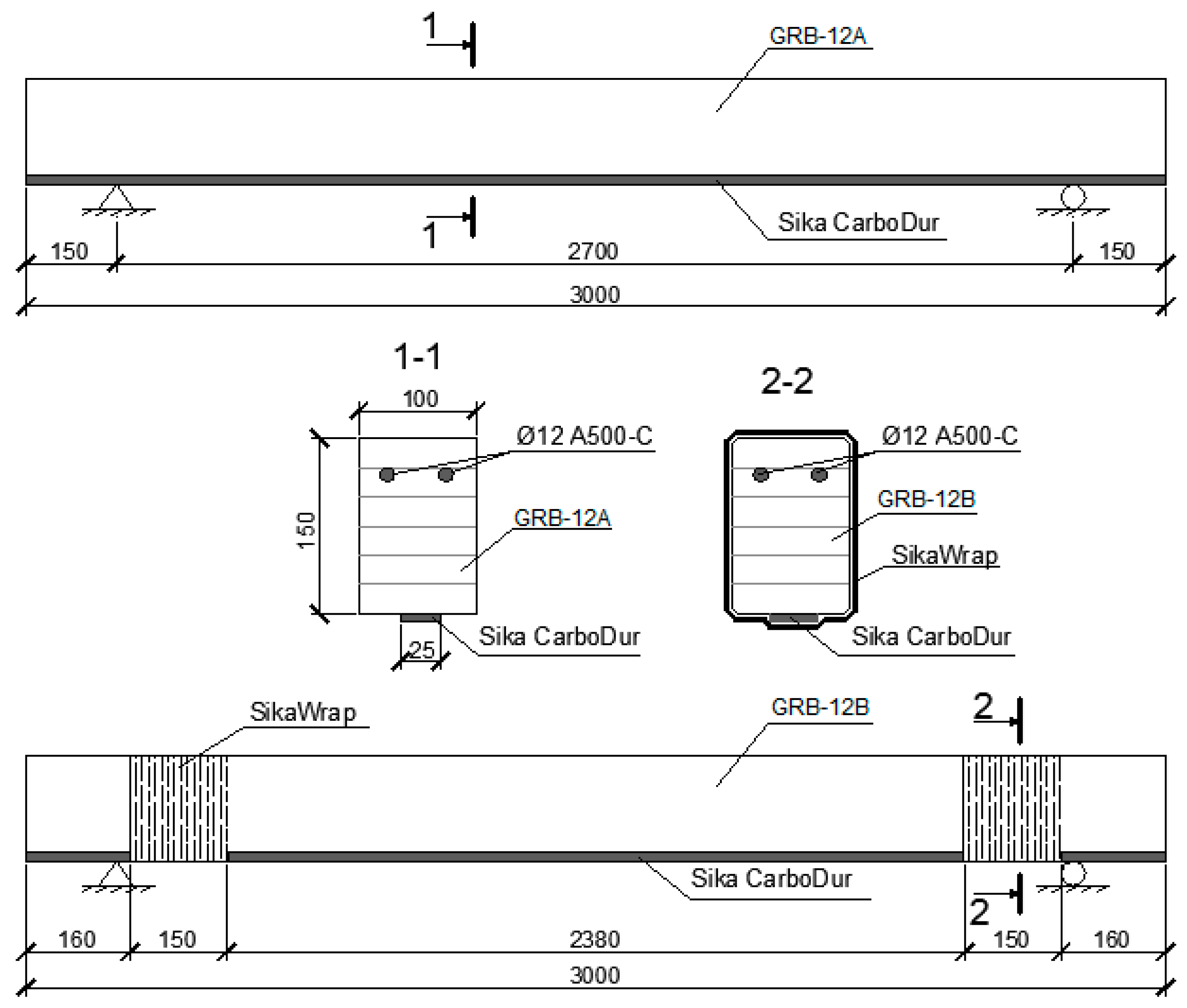
In accordance with the test program, two series of glued laminated beams with a cross-section (Figure 1) of 100 × 150 mm and length of 3000 mm were prepared (Table 1). Wood relative humidity was 12%. The strength of the glued wood for compression along the fibers was 49 MPa.
Therefore, four beams were made for the experiment research. The first series included two nonreinforced GB-A and GB-B beams made of glued laminated wood. The GB-A and GB-B beams, made of 25 mm planed pine boards and glued with the help of resorcinol adhesive, were tested as samples to determine the damaging loading and layer deformations along the height of the element in the pure bending zone. The second series consisted of two glued laminated reinforced GRB-12A and GRB-12B beams that contained, in the compressed zone, steel-bar reinforcement of 12 mm in diameter, and carbon–plastic ribbon reinforcement made of the SikaCarboDurS-512 carbon fiber in the stretched zone. The difference between the two beams of the second series was that the ribbon-reinforced composite in the GRB-12B beam was additionally anchored near the supporting flats in order to prevent premature ribbon lift. The SikaWrap-230 C carbon fiber sheet, glued along the perimeter of the beam near the supporting flats, was used for anchoring (Figure 1).
Since it is not possible to bend the sheet at an acute angle, sloped edges with a radius of at least 20 mm appeared at the places of its gluing.
The manufacture of the beams and their testing were carried out in a certified laboratory of the Department of Industrial, Civil Engineering, and Engineering Structures of the National University of Water and Environmental Engineering (NUVGP). Each of the nonreinforced beams of the first series was separately glued, while the reinforced beams of the second series were produced in several stages.
In the first instance, two steel reinforcement bars of 12 mm in diameter that were made from the steel of the A500S class periodic profile were fastened with the help of the glue epoxy in the premade dappings of the second-to-last board of the upper compressed zone. Strain sensors for measuring the deformations of the steel reinforcement were glued to the naked edges of the bars in the middle of the beam span. Later on, a stack of boards was glued under pressure with the help of resorcinol adhesive on a special stand. After the glue hardened, the SikaDur-30 adhesive was applied to glue the 1.2 mm thick and 25 mm wide SikaCarboDurS-512 ribbon composite from the bottom of the stretched zone. Finally, the SikaWrap-230 C sheet was glued across the element to the GRB-12B beam edges with the help of the SikaDur-330 adhesive to securely anchor the SikaCarboDurS-512 ribbon composite.
Ready-to-test beams [22] were mounted onto the hinged movable and immovable support. The loading was applied by means of a hydraulic jack by 5%–10% of the anticipated destructive loading and controlled by means of a ring dynamometer. The scheme of the plant for testing the research beams under the cross-bending is shown in Figure 2.
Tensometric sensors with a base of 20 mm and resistance of 201 ± 0.7 ohm were mounted and spaced at 1.5 cm in the middle of the span along the perimeter of the cross-section of the beam to determine the relative deformations of the wood. The same sensors were on the metal reinforcement. All sensors were glued with BF-2 glue, and the surface in their location was prepolished and degreased. Sensor imaging data were measured using the strain-sensor measuring system and recorded on the PC.
On the basis of the conducted experiment research, layer-relative deformations of the wood along the height of the sample cross-section were obtained, and, after processing the graphical charts of the deformation of the wood fibers, the metal and composite reinforcement of the bending element under the action of a single-use short-term loading was constructed.
The layer-relative deformations in the sample cross-section in the pure bending zone of the two nonreinforced sample twin beams under the action of the growing short-term single-use loading were practically the same. Figure 3 shows the layer deformations in the sample cross-section of the sample nonreinforced glued laminated beam made of the GB-A wood under the growing short-term single-use external loading. The fracture of the GB-A beam occurred at the bending moment of 23.86 kNm, while the GB-B element fractured at the moment of 22.05 kNm.
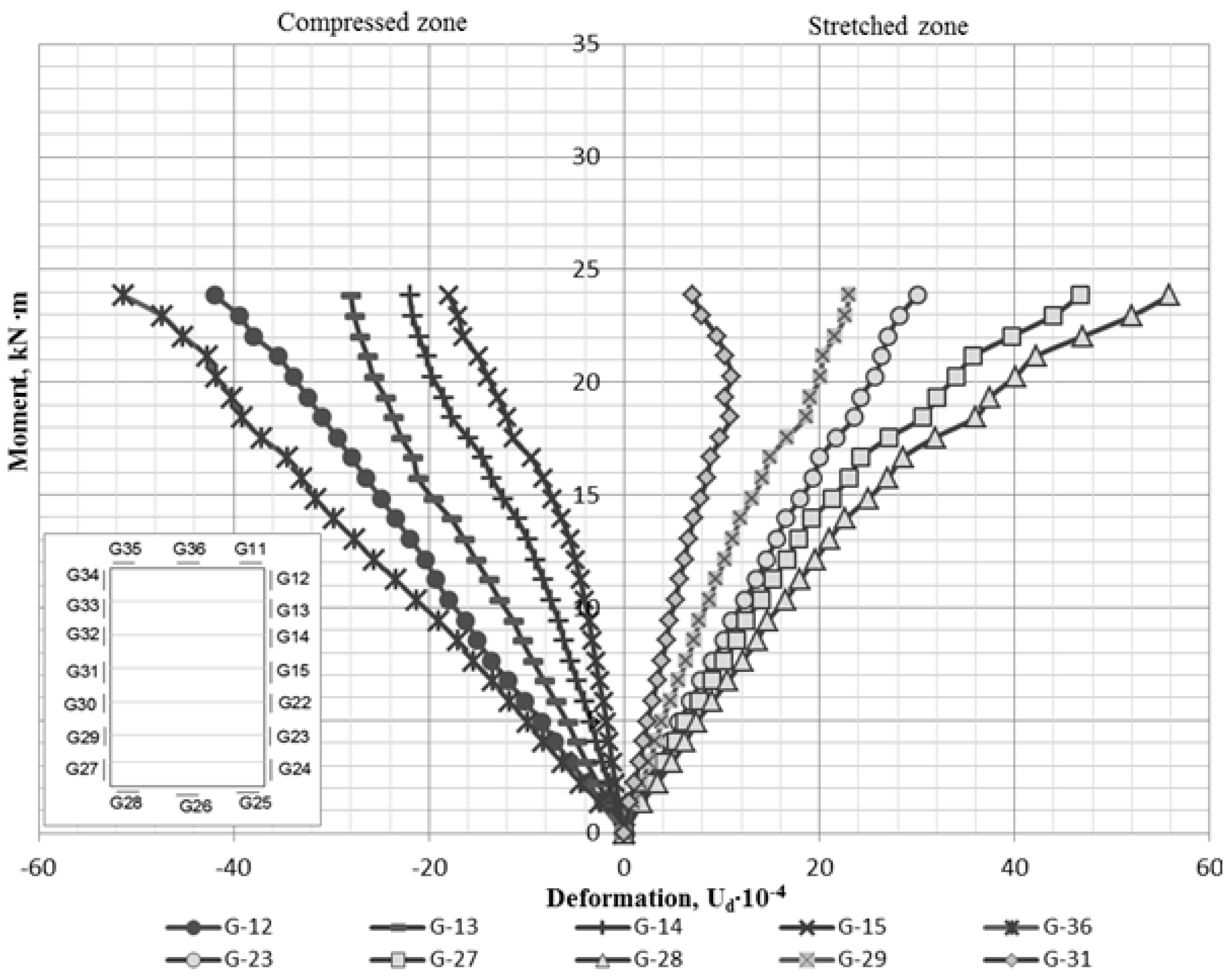
The layer-relative deformations along the height of the sample cross-section in the pure bending zone of the reinforced GRB-12A beam (Figure 4) at each level of the growing loading application were significantly smaller in comparison with those of the nonreinforced beams (Figure 3). The maximal relative deformations of GRB-12A in the compressed zone were observed in the wood layer that was the most remote from the neutral line. In the stretched zone, the greatest relative deformations were observed in the behavior of the SikaCarboDurS-512 ribbon composite, which joined with the wood of this zone and shared part of the loading itself.
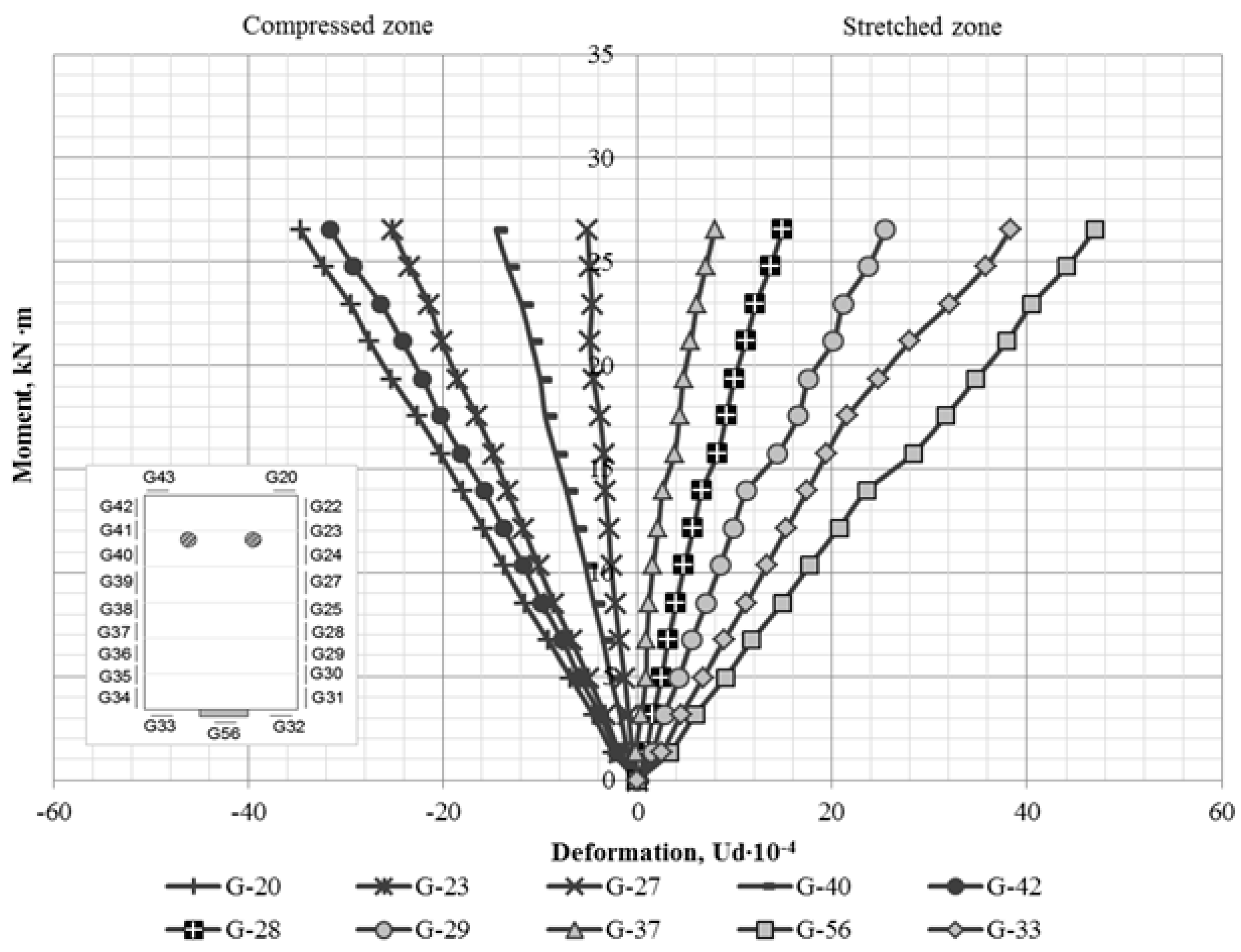
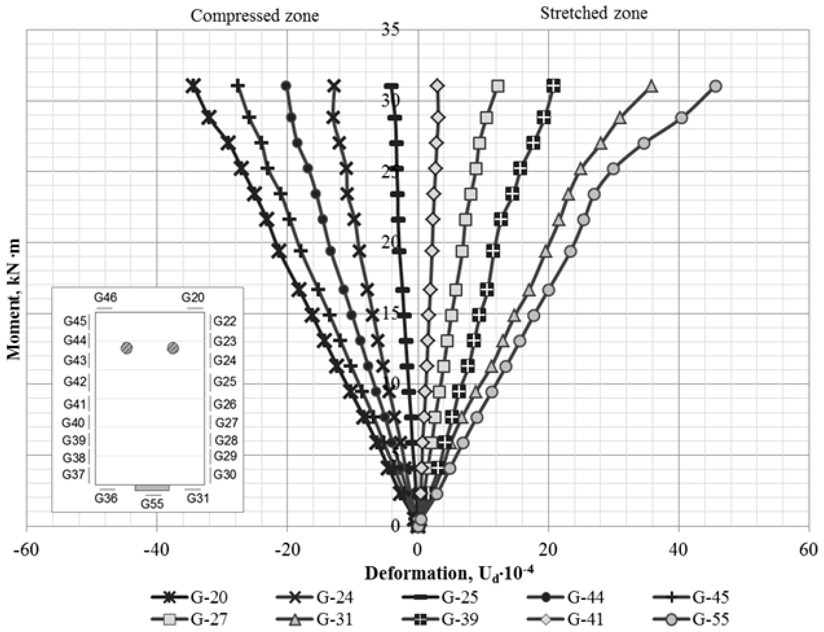
On the other hand, the deformations of the GRB-12B beam, which was reinforced with steel reinforcement made of two 12 mm class A 500 bars in the compressed zone and the SikaCarboDurS-512 ribbon composite and the SikaWrap-230 C sheet, turned out to be smaller than the deformations of the GRB-12A in the same layers of the sample cross-section of the pure bending zone at the same levels of application of the single-use short-term loading (Figure 4 and Figure 5). The fracture of the GRB-12A and GRB-12B beams occurred at the bending moments of 26.55 and 31.05 kNm, respectively.
The sensors that were located in the compressed zone on the steel reinforcement and on the outside wood at the same distance from the neutral line in the sample cross-section of both reinforced beams testified that they were deformed almost identically from the very start of loading application and until destruction. This proves their good joint work in the reinforced element made of glued laminated wood (Figure 6).
Figure 7 shows the deformation charts that were the most remote from the neutral line, showing that they possessed the most stressed wood fibers in the compressed and stretched zones of the nonreinforced GB-A and GB-B beams, and the reinforced GRB-12A and GRB-12B beams. Deformations of the most distant fibers of the sample cross-section of the pure bending zone in the beams of the nonreinforced GB-A and GB-B under the same level of the bending moment from the action of the external loading application was virtually the same. These relative deformations were greater than the deformations that arose in the reinforced GRB-12A and GRB-12B beams.
Figure 7 shows that the deformations in the wood layers that were the most remote from the neutral line in the compressed and stretched zones of the sample cross-section occurring in the GRB-12B beam, and they were significantly smaller than those in the GRB-12A beam.
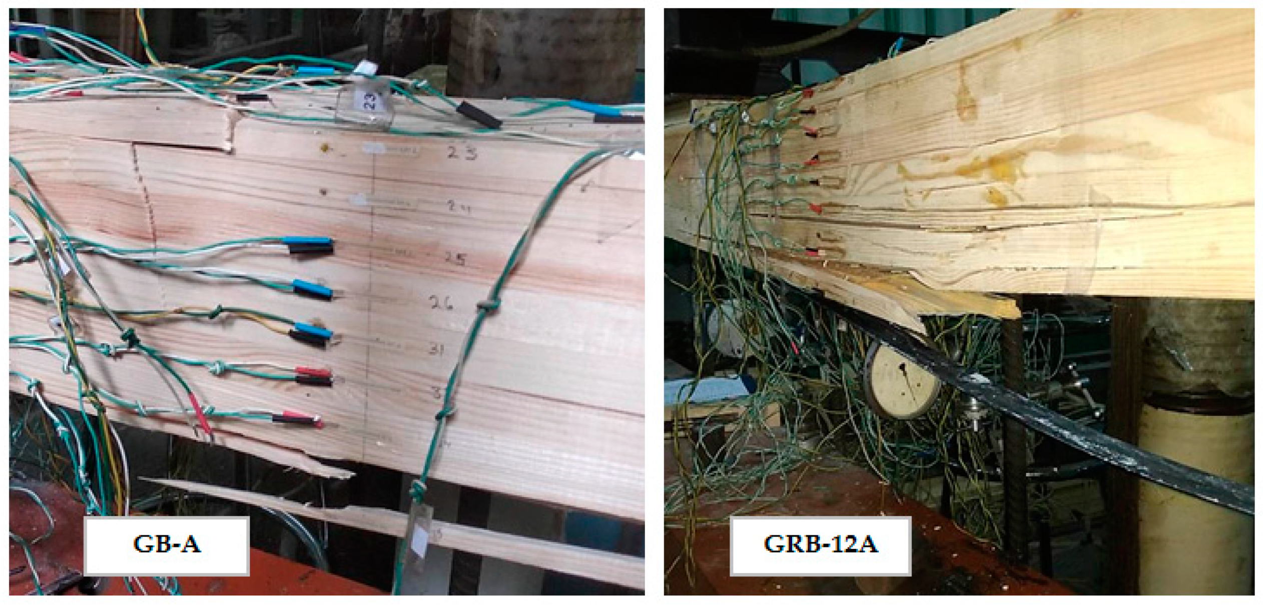
The massive fracture of all beams was due to the breaking of the fibers at the stretched zone of the wood with the separation of the SikaCarboDurS-512 composite tape within the reinforced elements. The fracture pattern of the unreinforced GB-A beams and reinforced GRB-12B beams is shown in Figure 8.
3. Discussion
As a result of the conducted experiment research, data on the deformability in the sample cross-section of the glued laminated wooden beams with combined reinforcement were obtained. The similarity of the deformation curves of the glued laminated wood under the effect of increasing load applications in different layers along the height of the compressed and stretched zones in the beams with combined reinforcement and the unreinforced elements was established.
The use of a 2 Ø 12 mm steel-bar reinforcement of the A500C class in the compressed zone and the SikaCarboDurS-512 ribbon composite in the stretched zone reduced the maximal relative deformations of wood in the sample cross-section by 30% compared to deformations of the most stressed fibers of the nonreinforced beams. The use of the SikaWrap-230 C composite sheet for the additional anchoring of the ribbon slightly increased the bearing capacity of the second-series samples, but the relative deformations in the sample cross-section before the destruction of GRB-12A and GRB-12B were virtually identical. However, under the action of the loading at which the GRB-12A sample collapsed, the maximal deformations of the GRB-12B sample wood were smaller by 25%.
The behavior of the GRB-12A and GRB-12B reinforced beams made from glued laminated wood showed good joint work of both the steel reinforcement with wood in the compressed zone, and the SikaCarboDurS-512 ribbon composite with wood in the stretched zone at all the stages of the stress–strain state until destruction.
The idea of the elastic–plastic deformation process of different layers of the compressed and stretched cross-section areas was developed on the basis of obtained results from experiment and theoretical studies of wood resistance to load-bearing characteristics being a part of the reinforced and unreinforced bending members. This suggests the possibility for further development of a new design-deformation method for structural members made of glued wood to be harmonized with European standards. In the future, on the basis of the experiment research results, a method of calculating such elements will be developed.
4. Conclusions
- The deformability of glued laminated beams with combined reinforcement was studied, under which the steel reinforcement of the periodic profile was placed in the dappings of the upper compressed zone, while a ribbon-reinforced composite was glued to the bottom of the stretched zone.
- The relative deformations of different layers of wood on the height of the calculated cross-section, metal, and composite tape reinforcement Sika CarboDur S-512, and the joint work of steel and composite reinforcement with compatible wood layers, were observed.
- The use of a 2 Ø 12 mm steel-bar reinforcement of the A500C class in the compressed zone and the SikaCarboDurS-512 ribbon composite in the stretched zone reduced the maximal relative deformations of the wood in the sample cross-section by 30% compared to the deformations of the most stressed fibers of the nonreinforced beams.
- The behavior of the GRB-12A and GRB-12B reinforced beams made from glued laminated wood showed the good joint work of both the steel reinforcement with wood in the compressed zone, and the SikaCarboDurS-512 ribbon composite with wood in the stretched zone at all stages of the stress–strain state until destruction.
Author Contributions
Investigation: J.S.-P., M.P. and V.K.; Conceptualization: S.S.G., S.H. and P.G. All authors have read and agreed to the published version of the manuscript.
Funding
This research received no external funding
Conflicts of Interest
The authors declare no conflict of interest.
References
- Gomon, S.S.; Pavlyuk, A.P. Deformity of solid wood beams in oblique bending conditions. Resour. -Sav. Mater. Struct. Build. Struct. 2016, 33, 135–140. [Google Scholar]
- Shchuko, V.Y.; Roshchina, S.I. Reinforced Wooden Constructions in Building; Vl.SU manual: Vladimir, Russia, 2002; p. 68. [Google Scholar]
- Repin, V.A. Wooden Beams with a Rational Reinforcement; The Dissertation: Vladimir, Russia, 2000; p. 158. [Google Scholar]
- Bondarchuk, T.B.; Bashynskyy, O.I.; Peleshko, M.Z. Carrying capacity and fire resistance of wooden beams reinforced with external tape reinforcement. Bull. LSUBZHD 2014, 9, 184–189. [Google Scholar]
- Turkovskiy, S.B.; Pogoreltsev, A.A. Wooden structures based on oblique glued rods. In Building Materials, Equipment, Technologies of the 21st Century; USDA: Washington, DC, USA, 2008; Volume 6. [Google Scholar]
- Koscheev, A.A.; Lukin, M.V.; Roshchina, S.I. Investigation of glued in bars strength and deformability indexes with in frame work of research of wood reinforcement with cable reinforcement. Mater. Sci. Eng. 2019, 687, 033023. [Google Scholar]
- Demchyna, B.H.; Surmay, M.I.; Kravz, A.R.; Blyakhar, T.Y. Experience of manufacturing laminated-beam beams reinforced with non-metallic reinforcement, Modern building materials, structures and innovative technologies of construction of buildings and structures. Bull. DONNACEA 2010, 5, 193–197. [Google Scholar]
- Stoyanov, V.V. Strengthening of beam structures by reinforcement layer by layer. Construction 2013, 11, 44–47. [Google Scholar]
- Yermolenko, D.A.; Ishchenko, M.S. Strength and deformability of glued wood beams reinforced with polymer mesh. Acad. J. 2017, 2, 140–147. [Google Scholar]
- Gugutsidze, G.; Draškovič, F. Reinforcement of timber beams with carbon fibers reinforced plastics, Slovak. J. Civ. Eng. 2010, 2, 1–6. [Google Scholar]
- Basterra, L.A.; Balmori, J.A.; Morillas, L.; Acuña, L.; Casado, M. Internal reinforcement of laminated duo beams of low—grade timber with GFRP sheets. Constr. Build. Mater. 2017, 154, 914–920. [Google Scholar] [CrossRef]
- Kim, Y.J.; Harries, K.A. Modeling of timber beams strengthened with various CFRP composites. Eng. Struct. 2010, 32, 3225–3234. [Google Scholar] [CrossRef]
- Yahyaei-Moayyed, M.; Taheri, F. Experimental and computational investigations into creep response of AFRP reinforced timber beams. Compos. Struct. 2011, 93, 616–628. [Google Scholar] [CrossRef]
- Rajczyk, M.; Jończyk, D. Behavior of glulam beams strengthened with BFRP bars. Mater. Sci. Eng. 2019, 603. [Google Scholar] [CrossRef]
- Rescalvo, F.J.; Valverde-Palacios, I.; Suarez, E.; Gallego, A. Experimental and analytical analysis for bending load capacity of old timber beams with defects when reinforced with carbon fiber strips. Compos. Struct. 2018, 186, 29–38. [Google Scholar] [CrossRef]
- Gomon, S.S.; Polishchuk, M.V. Combined reinforcement of glued timber beams, Effective technologies and structures in construction and village architecture. Development of innovative models of ecological settlements of Carpathian and Carpathian Mountains. In Proceedings of the Abstracts of the International Scientific and Practical Conference, Dublin, Ireland, 15–17 May 2019; pp. 99–100. [Google Scholar]
- Gomon, S.; Gomon, S.; Karavan, V.; Gomon, P.; Sobczak-Piastka, J. Investigation of solid and glued wood on the effect of variables of low-cycle repeated loads. In AIP Conference Proceedings; AIP Publishing Center: New York, NY, USA, 2019; Volume 2077, p. 020020. [Google Scholar]
- Gomon, S.; Gomon, S.; Karavan, V.; Gomon, P.; Podhorecki, A. Calculated cross-sectional model and stages of the stress–strain state of the wood element for transverse bending. In AIP Conference Proceedings; AIP Publishing Center: New York, NY, USA, 2019; Volume 2077, p. 020019. [Google Scholar]
- Gomon, S.; Gomon, S.; Gomon, P.; Pavluk, A.; Sobczak-Piastka, J. Complete deflections of glued beams in the conditions of oblique bend for the effects of low cycle loads. In AIP Conference Proceedings; AIP Publishing Center: New York, NY, USA, 2019; Volume 2077, p. 020021. [Google Scholar]
- Bedon, C.; Louter, C. Numerical analysis of glass-FRP post tension beams—Review and assessment. Compos. Struct. 2017, 177, 129–140. [Google Scholar] [CrossRef] [Green Version]
- Kononchuk, O. The results of experimental studies of reinforced concrete beams reinforced with composite materials. Resour. Sav. Mater. Struct. Build. Struct. 2012, 23, 479–486. [Google Scholar]
- Gomon, S.S.; Polishchuk, M.V. The patent for the utility model No. 135229 Ukraine, IPC E04C 3/12 (2006.01). Glued wooden beam. No. u 201900104, 25 June 2019. Bulletin No. 12.
Figure 1.
Scheme of reinforcing beams by means of metal and composite reinforcement.

Figure 2.
Scheme of experiment plant for testing beams made from glued laminated wood under bending: (1) studied beam; (2) metal traverse; (3) dynamometer; (4) jack; (5) metal plate; (6) wooden plate; (7) strain sensors.
Figure 2.
Scheme of experiment plant for testing beams made from glued laminated wood under bending: (1) studied beam; (2) metal traverse; (3) dynamometer; (4) jack; (5) metal plate; (6) wooden plate; (7) strain sensors.
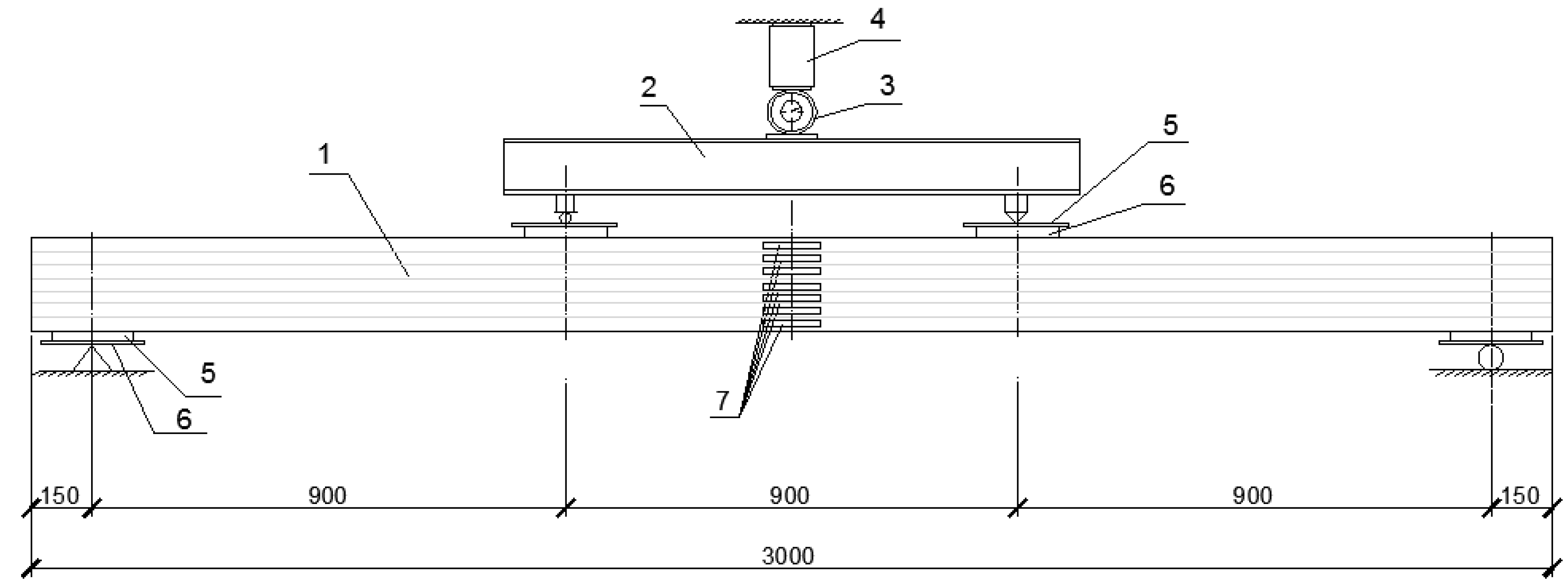
Figure 3.
Graphical chart of layer deformation of cross-section fibers of GB-A beam in span middle.

Figure 4.
Graphical chart of layer deformation of cross-section fibers of GRB-12A beam in span middle.
Figure 4.
Graphical chart of layer deformation of cross-section fibers of GRB-12A beam in span middle.

Figure 5.
Graphical chart of layer deformation of sample cross-section fibers of GRB-12B beam in span middle.
Figure 5.
Graphical chart of layer deformation of sample cross-section fibers of GRB-12B beam in span middle.

Figure 6.
Graphical charts of wood- and steel-reinforcement deformations of GRB-12A and GRB-12B beams.
Figure 6.
Graphical charts of wood- and steel-reinforcement deformations of GRB-12A and GRB-12B beams.
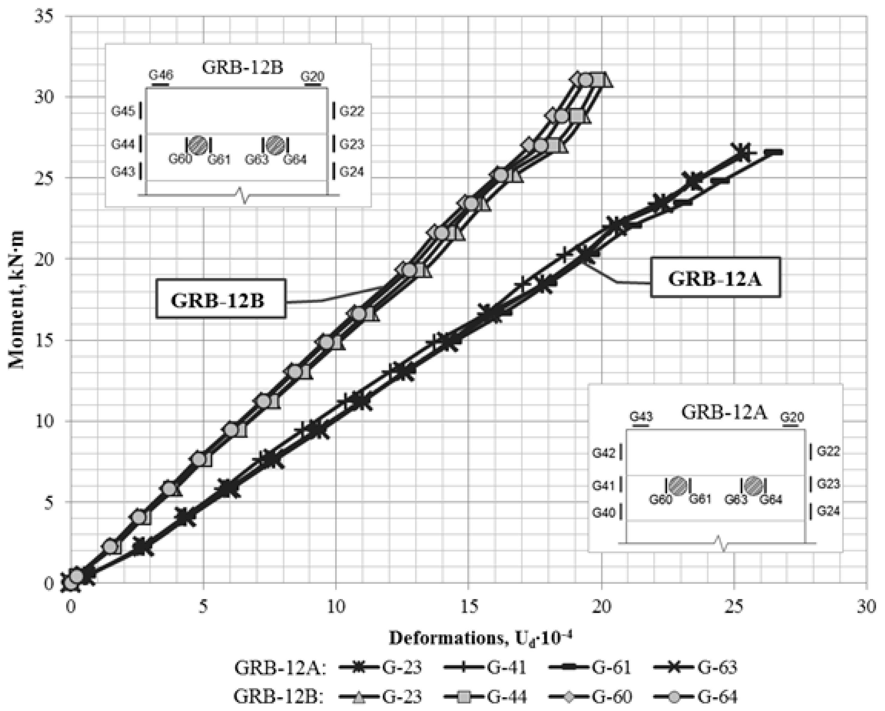
Figure 7.
Graphical charts of deformations of most stressed fibers of wood in GB-A, GB-B, GRB-12A, and GRB-12B beams.
Figure 7.
Graphical charts of deformations of most stressed fibers of wood in GB-A, GB-B, GRB-12A, and GRB-12B beams.
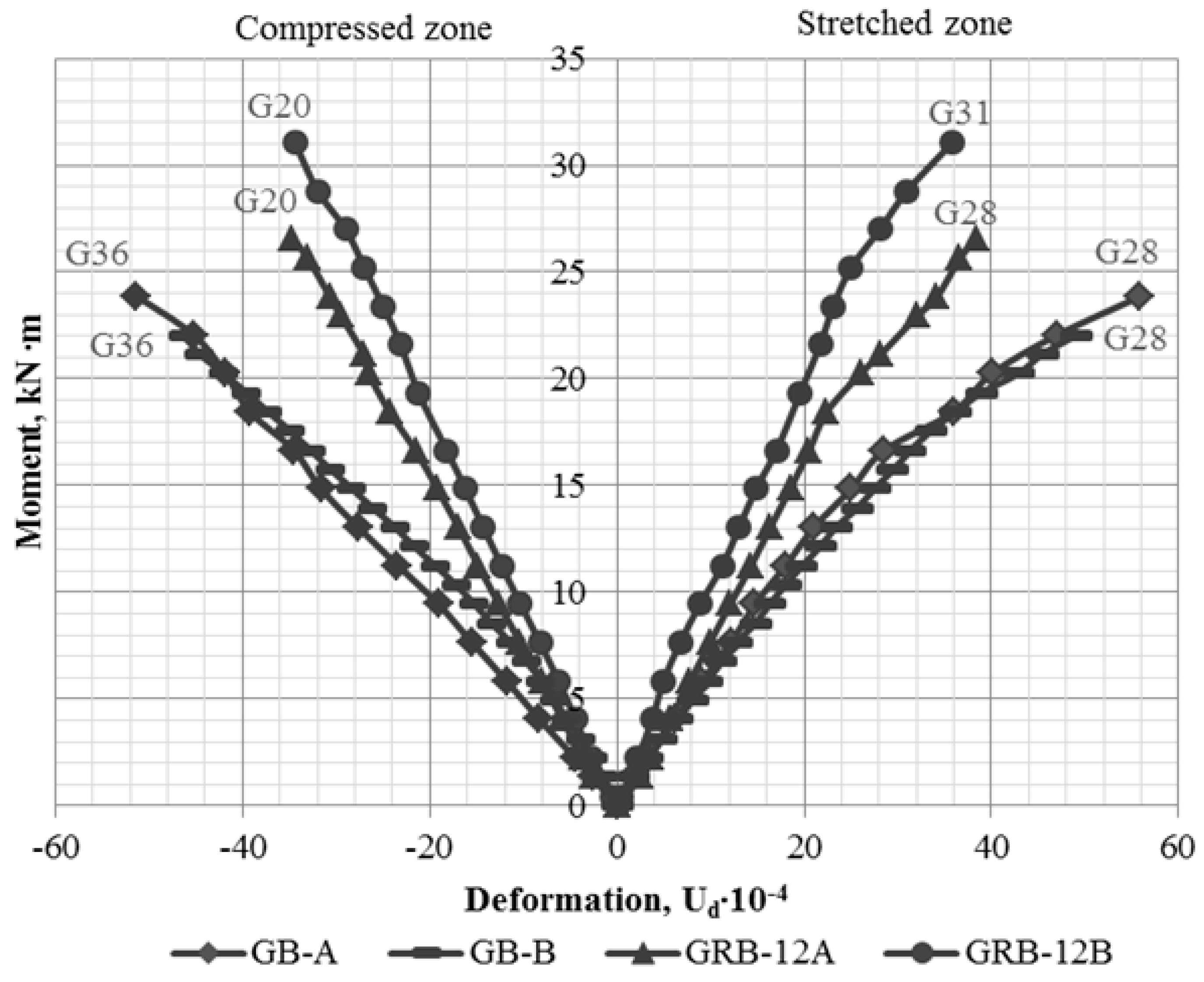
Figure 8.
Fracture pattern of GB-A and GRB-12A beams.

Table 1.
Bulk samples for experiment studies.
| Series Number | Marking | Number of Samples | Reinforcement |
|---|---|---|---|
| I | GB-A | 1 | Nonreinforced |
| GB-B | 1 | Nonreinforced | |
| II | GRB-12A | 1 | 2Ø12 A500C + SikaCarboDurS-512 |
| GRB-12B | 1 | 2Ø12 A500C + SikaCarboDurS-512 + SikaWrap-230 C |
© 2020 by the authors. Licensee MDPI, Basel, Switzerland. This article is an open access article distributed under the terms and conditions of the Creative Commons Attribution (CC BY) license (http://creativecommons.org/licenses/by/4.0/).
Share and Cite
MDPI and ACS Style
Sobczak-Piąstka, J.; Gomon, S.S.; Polishchuk, M.; Homon, S.; Gomon, P.; Karavan, V. Deformability of Glued Laminated Beams with Combined Reinforcement. Buildings 2020, 10, 92. https://doi.org/10.3390/buildings10050092
AMA Style
Sobczak-Piąstka J, Gomon SS, Polishchuk M, Homon S, Gomon P, Karavan V. Deformability of Glued Laminated Beams with Combined Reinforcement. Buildings. 2020; 10(5):92. https://doi.org/10.3390/buildings10050092
Chicago/Turabian StyleSobczak-Piąstka, Justyna, Svyatoslav S. Gomon, Mykola Polishchuk, Sviatoslav Homon, Petro Gomon, and Victor Karavan. 2020. "Deformability of Glued Laminated Beams with Combined Reinforcement" Buildings 10, no. 5: 92. https://doi.org/10.3390/buildings10050092
Note that from the first issue of 2016, this journal uses article numbers instead of page numbers. See further details here.